EP3529926B1 - Dispositifs, procédés et programmes informatiques de communication sans fil à accès multiple - Google Patents
Dispositifs, procédés et programmes informatiques de communication sans fil à accès multiple Download PDFInfo
- Publication number
- EP3529926B1 EP3529926B1 EP16795301.7A EP16795301A EP3529926B1 EP 3529926 B1 EP3529926 B1 EP 3529926B1 EP 16795301 A EP16795301 A EP 16795301A EP 3529926 B1 EP3529926 B1 EP 3529926B1
- Authority
- EP
- European Patent Office
- Prior art keywords
- resource elements
- network node
- node device
- channel
- channel vectors
- Prior art date
- Legal status (The legal status is an assumption and is not a legal conclusion. Google has not performed a legal analysis and makes no representation as to the accuracy of the status listed.)
- Active
Links
Images



Classifications
-
- H—ELECTRICITY
- H04—ELECTRIC COMMUNICATION TECHNIQUE
- H04W—WIRELESS COMMUNICATION NETWORKS
- H04W72/00—Local resource management
- H04W72/04—Wireless resource allocation
- H04W72/044—Wireless resource allocation based on the type of the allocated resource
- H04W72/0446—Resources in time domain, e.g. slots or frames
-
- H—ELECTRICITY
- H04—ELECTRIC COMMUNICATION TECHNIQUE
- H04L—TRANSMISSION OF DIGITAL INFORMATION, e.g. TELEGRAPHIC COMMUNICATION
- H04L5/00—Arrangements affording multiple use of the transmission path
- H04L5/003—Arrangements for allocating sub-channels of the transmission path
- H04L5/0032—Distributed allocation, i.e. involving a plurality of allocating devices, each making partial allocation
- H04L5/0035—Resource allocation in a cooperative multipoint environment
-
- H—ELECTRICITY
- H04—ELECTRIC COMMUNICATION TECHNIQUE
- H04B—TRANSMISSION
- H04B7/00—Radio transmission systems, i.e. using radiation field
- H04B7/02—Diversity systems; Multi-antenna system, i.e. transmission or reception using multiple antennas
- H04B7/04—Diversity systems; Multi-antenna system, i.e. transmission or reception using multiple antennas using two or more spaced independent antennas
- H04B7/0413—MIMO systems
-
- H—ELECTRICITY
- H04—ELECTRIC COMMUNICATION TECHNIQUE
- H04B—TRANSMISSION
- H04B7/00—Radio transmission systems, i.e. using radiation field
- H04B7/02—Diversity systems; Multi-antenna system, i.e. transmission or reception using multiple antennas
- H04B7/04—Diversity systems; Multi-antenna system, i.e. transmission or reception using multiple antennas using two or more spaced independent antennas
- H04B7/0413—MIMO systems
- H04B7/0417—Feedback systems
- H04B7/0421—Feedback systems utilizing implicit feedback, e.g. steered pilot signals
-
- H—ELECTRICITY
- H04—ELECTRIC COMMUNICATION TECHNIQUE
- H04B—TRANSMISSION
- H04B7/00—Radio transmission systems, i.e. using radiation field
- H04B7/02—Diversity systems; Multi-antenna system, i.e. transmission or reception using multiple antennas
- H04B7/04—Diversity systems; Multi-antenna system, i.e. transmission or reception using multiple antennas using two or more spaced independent antennas
- H04B7/0413—MIMO systems
- H04B7/0426—Power distribution
- H04B7/0434—Power distribution using multiple eigenmodes
-
- H—ELECTRICITY
- H04—ELECTRIC COMMUNICATION TECHNIQUE
- H04B—TRANSMISSION
- H04B7/00—Radio transmission systems, i.e. using radiation field
- H04B7/02—Diversity systems; Multi-antenna system, i.e. transmission or reception using multiple antennas
- H04B7/04—Diversity systems; Multi-antenna system, i.e. transmission or reception using multiple antennas using two or more spaced independent antennas
- H04B7/0413—MIMO systems
- H04B7/0456—Selection of precoding matrices or codebooks, e.g. using matrices antenna weighting
-
- H—ELECTRICITY
- H04—ELECTRIC COMMUNICATION TECHNIQUE
- H04B—TRANSMISSION
- H04B7/00—Radio transmission systems, i.e. using radiation field
- H04B7/02—Diversity systems; Multi-antenna system, i.e. transmission or reception using multiple antennas
- H04B7/04—Diversity systems; Multi-antenna system, i.e. transmission or reception using multiple antennas using two or more spaced independent antennas
- H04B7/06—Diversity systems; Multi-antenna system, i.e. transmission or reception using multiple antennas using two or more spaced independent antennas at the transmitting station
- H04B7/0613—Diversity systems; Multi-antenna system, i.e. transmission or reception using multiple antennas using two or more spaced independent antennas at the transmitting station using simultaneous transmission
- H04B7/0615—Diversity systems; Multi-antenna system, i.e. transmission or reception using multiple antennas using two or more spaced independent antennas at the transmitting station using simultaneous transmission of weighted versions of same signal
- H04B7/0617—Diversity systems; Multi-antenna system, i.e. transmission or reception using multiple antennas using two or more spaced independent antennas at the transmitting station using simultaneous transmission of weighted versions of same signal for beam forming
-
- H—ELECTRICITY
- H04—ELECTRIC COMMUNICATION TECHNIQUE
- H04J—MULTIPLEX COMMUNICATION
- H04J11/00—Orthogonal multiplex systems, e.g. using WALSH codes
- H04J11/0023—Interference mitigation or co-ordination
- H04J11/0026—Interference mitigation or co-ordination of multi-user interference
- H04J11/0036—Interference mitigation or co-ordination of multi-user interference at the receiver
- H04J11/0046—Interference mitigation or co-ordination of multi-user interference at the receiver using joint detection algorithms
-
- H—ELECTRICITY
- H04—ELECTRIC COMMUNICATION TECHNIQUE
- H04L—TRANSMISSION OF DIGITAL INFORMATION, e.g. TELEGRAPHIC COMMUNICATION
- H04L1/00—Arrangements for detecting or preventing errors in the information received
- H04L1/0001—Systems modifying transmission characteristics according to link quality, e.g. power backoff
- H04L1/0036—Systems modifying transmission characteristics according to link quality, e.g. power backoff arrangements specific to the receiver
- H04L1/0038—Blind format detection
-
- H—ELECTRICITY
- H04—ELECTRIC COMMUNICATION TECHNIQUE
- H04L—TRANSMISSION OF DIGITAL INFORMATION, e.g. TELEGRAPHIC COMMUNICATION
- H04L5/00—Arrangements affording multiple use of the transmission path
- H04L5/003—Arrangements for allocating sub-channels of the transmission path
- H04L5/0048—Allocation of pilot signals, i.e. of signals known to the receiver
-
- H—ELECTRICITY
- H04—ELECTRIC COMMUNICATION TECHNIQUE
- H04W—WIRELESS COMMUNICATION NETWORKS
- H04W72/00—Local resource management
- H04W72/04—Wireless resource allocation
- H04W72/044—Wireless resource allocation based on the type of the allocated resource
- H04W72/0453—Resources in frequency domain, e.g. a carrier in FDMA
Definitions
- the present application relates to the field of wireless communications, and more particularly to a network node device, user equipment, and related methods and computer programs.
- Wireless systems typically utilize so called multiple access schemes to efficiently share available radio resources (e.g. time, frequency, power, etc.) with multiple users.
- These multiple access schemes include e.g. Orthogonal Frequency Division Multiple Access (OFDMA), Code Division Multiple Access (CDMA) and Time Division Multiple Access (TDMA).
- OFDMA Orthogonal Frequency Division Multiple Access
- CDMA Code Division Multiple Access
- TDMA Time Division Multiple Access
- Massive MIMO massive multiple-input and multiple-output, mMIMO
- NOMA Non-Orthogonal Multiple-Access
- the spatial channels between the users and the massive arrays need to be acquired.
- a conventional solution is to allocate a substantial portion of the time-frequency resources for channel estimation.
- Orthogonal pilot allocation for multiple users may be used to estimate the channels of the corresponding users which consume a notable amount of time-frequency resources.
- the intra-cell interference by orthogonal pilot allocation will vanish as the number of antennas increases.
- the inter-cell interference for the users that have the same pilot sequence will remain since the number of mutually orthogonal sequences is limited. This phenomenon is known as pilot contamination (a.k.a reference symbol (RS) contamination).
- RS reference symbol
- the pilot contamination can severely degrade the performance of the mMIMO systems.
- two cell-edge users employ the same pilot sequence, the interference among these users will remain despite the fact that the antenna arrays are equipped with many antenna elements.
- WO 2015/149812 A1 discloses a system for determining channel coefficients of channels in a wireless cellular network.
- the wireless cellular network comprises a plurality of cells wherein each cell comprises a base station configured to communicate with users within the cell and wherein a communication path between one of the users and one of the base stations define one of the channels.
- the system comprises a pilot generation unit configured to assign pilot sequences randomly among the users and a pilot processing unit configured to filter the pilot sequences received from a user of interest so that the channel coefficient of the channel of the user of interest is determined.
- the pilot sequences received from the user of interest are contaminated by other non-orthogonal or identical pilot sequences from other users of the cell of interest or other cells.
- the filter is configured so that the contamination caused by the other non-orthogonal or identical pilot sequences from the other users is reduced.
- WO 2016/064246 A1 discloses a pre-5th-Generation (5G) or 5G communication system to be provided for supporting higher data rates Beyond 4th-Generation (4G) communication system such as Long Term Evolution (LTE).
- 5G pre-5th-Generation
- 4G 4th-Generation
- Methods and apparatus for vector quantization of feedback and processing of vector quantized feedback components A method of operating a terminal for vector quantization of feedback components is provided. The method includes computing channel coefficients based on at least one channel measurement and grouping the computed channel coefficients according to a grouping method. Additionally, the method includes performing vector quantization of the grouped channel coefficients using at least one codebook and transmitting a feedback signal including information for the quantized channel coefficients to a base station.
- BAYESTEH ALIREZA ET AL "Blind detection of SCMA for uplink grant-free multiple-access", 2014 11TH INTERNATIONAL SYMPOSIUM ON WIRELESS COMMUNICATIONS SYSTEMS (ISWCS), IEEE, (20140826), doi:10.1109/ISWCS.2014.6933472 discloses a blind detection solution, which is analyzed to support massive connectivity in a SCMA-based UL grant-free multiple access. It is based on two major components: i) blind detection of active pilots/users with reasonable complexity, and ii) blind decoding of active users' data with no knowledge of active codebook set. Different activity detection algorithms and schemes are disclosed, described, and analyzed. Simulation results are provided to evaluate the performance of the proposed schemes in various scenarios.
- a network node device comprising: a radio transceiver configured to receive a data sequence from a plurality of user equipment over a first set of resource elements and a second set of resource elements, wherein the first set of resource elements is mapped non-orthogonally and the second set of resource elements is mapped orthogonally; and a processor configured to: determine channel vectors based on at least the data sequence received over the first set of resource elements or the second set of resource elements, and utilize the data sequence received over the second set of resource elements to associate the determined channel vectors with each of the plurality of user equipment.
- Data from multiple users is multiplexed in a way that allows the receiving network node device to perform blind data detection to estimate spatial channels without uplink pilot resources, thereby avoiding pilot contamination as well as eliminating the pilot overhead and thereby resulting in efficient utilization of spectral resources.
- the processor is further configured to determine the channel vectors based on a scaled covariance matrix of the data sequence over at least one of the first set of resource elements and the second set of resource elements, determine eigenvalues and eigenvectors of the determined scaled covariance matrix, and scale the eigenvectors to obtain a candidate set of channel vectors. Based on how data from multiple users is multiplexed, the receiving network node device can identify a candidate set of channel vectors, thereby allowing blind data detection to estimate spatial channels without uplink pilot resources.
- the processor is further configured to perform the association of the channel vectors by determining correlations between the data sequence received over the second set of resource elements and the channel vectors in the obtained candidate set of channel vectors. Based on how data from multiple users is multiplexed, the receiving network node device can associate the identified candidate channel vectors with the transmitting user devices, thereby allowing blind data detection to estimate spatial channels without uplink pilot resources.
- the processor is further configured to perform the association of the channel vectors by: determining normalized average received power of the data sequence received over the second set of resource elements, and selecting a channel vector in the obtained candidate set of channel vectors with eigenvalue closest to the determined normalized average received power. Based on how data from multiple users is multiplexed, the receiving network node device can associate the identified candidate channel vectors with the transmitting user devices, thereby allowing blind data detection to estimate spatial channels without uplink pilot resources.
- the processor is further configured to determine the total number of resource elements in the first set of resource elements and the second set of resource elements based on radio channel coherence time and radio channel coherence bandwidth. Data from multiple users is multiplexed in a way that allows the receiving network node device to perform blind data detection to estimate spatial channels without uplink pilot resources, thereby avoiding pilot contamination as well as eliminating the pilot overhead and thereby resulting in efficient utilization of spectral resources.
- the processor is further configured to determine the number of resource elements in the second set of resource elements as the sum of uplink data layers transmitted from each of the plurality of user equipment, and the processor is further configured to determine the number of resource elements in the first set of resource elements as the difference between the total number of resource elements and the number of resource elements in the second set of resource elements.
- Data from multiple users is multiplexed in a way that allows the receiving network node device to perform blind data detection to estimate spatial channels without uplink pilot resources, thereby avoiding pilot contamination as well as eliminating the pilot overhead and thereby resulting in efficient utilization of spectral resources.
- the processor is further configured to cause the transceiver to send information about determined first and second sets of resource elements to the plurality of user equipment. Sending the information to the plurality of user equipment allows the plurality of user equipment to send their data multiplexed in a way that allows the receiving network node device to perform blind data detection to estimate spatial channels without uplink pilot resources, thereby avoiding pilot contamination as well as eliminating the pilot overhead, and thereby resulting in efficient utilization of spectral resources.
- the processor is further configured to determine the first set of resource elements and the second set of resource elements based on information stored in the network node device. Based on the stored information on how data from multiple users is multiplexed, the receiving network node device can associate the identified candidate channel vectors with the transmitting user devices, thereby allowing blind data detection to estimate spatial channels without uplink pilot resources.
- a method comprising: receiving, by a network node device, a data sequence from a plurality of user equipment over a first set of resource elements and a second set of resource elements, wherein the first set of resource elements is mapped non-orthogonally and the second set of resource elements is mapped orthogonally; determining, by the network node device, channel vectors based at least on the data sequence received over the first set of resource elements or the second set of resource elements; and utilizing, by the network node device, the data sequence received over the second set of resource elements to associate the determined channel vectors with each of the plurality of user equipment.
- Data from multiple users is multiplexed in a way that allows the receiving network node device to perform blind data detection to estimate spatial channels without uplink pilot resources, thereby avoiding pilot contamination as well as eliminating the pilot overhead, and thereby resulting in efficient utilization of spectral resources.
- the method further comprises: determining, by the network node device, the channel vectors based on a scaled covariance matrix of the data sequence over at least one of the first set of resource elements and the second set of resource elements; determining, by the network node device, eigenvalues and eigenvectors of the determined scaled covariance matrix; and scaling, by the network node device, the eigenvectors to obtain a candidate set of channel vectors. Based on how data from multiple users is multiplexed, the receiving network node device can identify a candidate set of channel vectors, thereby allowing blind data detection to estimate spatial channels without uplink pilot resources.
- the method further comprises performing the association of the channel vectors by: determining, by the network node device, correlations between the data sequence received over the second set of resource elements and the channel vectors in the obtained candidate set of channel vectors. Based on how data from multiple users is multiplexed, the receiving network node device can associate the identified candidate channel vectors with the transmitting user devices, thereby allowing blind data detection to estimate spatial channels without uplink pilot resources.
- the method further comprises performing the association of the channel vectors by: determining, by the network node device, normalized average received power of the data sequence received over the second set of resource elements; and selecting, by the network node device, a channel vector in the obtained candidate set of channel vectors with eigenvalue closest to the determined normalized average received power. Based on how data from multiple users is multiplexed, the receiving network node device can associate the identified candidate channel vectors with the transmitting user devices, thereby allowing blind data detection to estimate spatial channels without uplink pilot resources.
- the method further comprises: determining, by the network node device, the total number of resource elements in the first set of resource elements and the second set of resource elements based on radio channel coherence time and radio channel coherence bandwidth.
- Data from multiple users is multiplexed in a way that allows the receiving network node device to perform blind data detection to estimate spatial channels without uplink pilot resources, thereby avoiding pilot contamination as well as eliminating the pilot overhead, and thereby resulting in efficient utilization of spectral resources.
- the method further comprises: determining, by the network node device, the number of resource elements in the second set of resource elements as the sum of uplink data layers transmitted from each of the plurality of user equipment; and determining, by the network node device, the number of resource elements in the first set of resource elements as the difference between the total number of resource elements and the number of resource elements in the second set of resource elements.
- Data from multiple users is multiplexed in a way that allows the receiving network node device to perform blind data detection to estimate spatial channels without uplink pilot resources, thereby avoiding pilot contamination as well as eliminating the pilot overhead, and thereby resulting in efficient utilization of spectral resources.
- the method further comprises: sending, by the network node device, information about determined first and second sets of resource elements to the plurality of user equipment.
- Sending the information to the plurality of user equipment allows the plurality of user equipment to send their data multiplexed in a way that allows the receiving network node device to perform blind data detection to estimate spatial channels without uplink pilot resources, thereby avoiding pilot contamination as well as eliminating the pilot overhead, and thereby resulting in efficient utilization of spectral resources.
- the method further comprises: determining, by the network node device, the first set of resource elements and the second set of resource elements based on information stored in the network node device. Based on the stored information on how data from multiple users is multiplexed, the receiving network node device can associate the identified candidate channel vectors with the transmitting user devices, thereby allowing blind data detection to estimate spatial channels without uplink pilot resources.
- a computer program comprising program code is configured to perform the method, when the computer program is executed on a computer.
- Data from multiple users is multiplexed in a way that allows the receiving network node device to perform blind data detection to estimate spatial channels without uplink pilot resources, thereby avoiding pilot contamination as well as eliminating the pilot overhead, and thereby resulting in efficient utilization of spectral resources.
- a user equipment comprising: a processor configured to access a resource element assignment of a first set of resource elements and a second set of resource elements, wherein the first set of resource elements is mapped non-orthogonally and the second set of resource elements is mapped orthogonally; and a radio transceiver configured to transmit a data sequence to a network node device over the first set of resource elements and over the second set of resource elements.
- Data transmitted from the user equipment is multiplexed in a way that allows the receiving network node device to perform blind data detection to estimate spatial channels without uplink pilot resources, thereby avoiding pilot contamination as well as eliminating the pilot overhead, and thereby resulting in efficient utilization of spectral resources.
- the user equipment further comprises a storage configured to store the resource element assignment. Based on the stored information, data transmitted from the user equipment can be multiplexed in a way that allows the receiving network node device to perform blind data detection to estimate spatial channels without uplink pilot resources, thereby avoiding pilot contamination as well as eliminating the pilot overhead, and thereby resulting in efficient utilization of spectral resources.
- the radio transceiver is further configured to receive the resource element assignment from a network node device. Based on the received information, data transmitted from the user equipment can be multiplexed in a way that allows the receiving network node device to perform blind data detection to estimate spatial channels without uplink pilot resources, thereby avoiding pilot contamination as well as eliminating the pilot overhead, and thereby resulting in efficient utilization of spectral resources.
- a method comprising: accessing, by a user equipment, a resource element assignment of a first set of resource elements and a second set of resource elements, wherein the first set of resource elements is mapped non-orthogonally and the second set of re-source elements is mapped orthogonally; and transmitting, by the user equipment, a data sequence to a network node device over the first set of resource elements and over the second set of resource elements.
- Data transmitted from the user equipment is multiplexed in a way that allows the receiving network node device to perform blind data detection to estimate spatial channels without uplink pilot resources, thereby avoiding pilot contamination as well as eliminating the pilot overhead, and thereby resulting in efficient utilization of spectral resources.
- the method further comprises: storing, by the user equipment, the resource element assignment. Based on the stored information, data transmitted from the user equipment can be multiplexed in a way that allows the receiving network node device to perform blind data detection to estimate spatial channels without uplink pilot resources, thereby avoiding pilot contamination as well as eliminating the pilot overhead, and thereby resulting in efficient utilization of spectral resources.
- the method further comprises: receiving, by the user equipment, the resource element assignment from a network node device. Based on the received information, data transmitted from the user equipment can be multiplexed in a way that allows the receiving network node device to perform blind data detection to estimate spatial channels without uplink pilot resources, thereby avoiding pilot contamination as well as eliminating the pilot overhead, and thereby resulting in efficient utilization of spectral resources.
- a computer program comprising program code is configured to perform the method, when the computer program is executed on a computer.
- Data transmitted from the user equipment is multiplexed in a way that allows the receiving network node device to perform blind data detection to estimate spatial channels without uplink pilot resources, thereby avoiding pilot contamination as well as eliminating the pilot overhead, and thereby resulting in efficient utilization of spectral resources.
- multiple-access schemes are discussed in which data of multiple users is multiplexed in a way to facilitate blind data detection in mMIMO systems in order to enable a network node, such as a mMIMO access node, to estimate the channels of the users without dedicated pilot resources for channel estimation.
- a network node such as a mMIMO access node
- resource elements may be divided into two sets in each coherence window of the time-frequency plane that spans a coherence time, T c , (i.e. a time duration over which the radio channel can be assumed almost unchanged) and a coherence bandwidth, B c , (i.e. a bandwidth over which the radio channel can be assumed almost unchanged).
- T c coherence time
- B c coherence bandwidth
- the coherence time depends on the velocity of users and a typical number in long-term evolution (LTE) systems is around 0.5 milliseconds.
- the coherence bandwidth depends on the multi-path delay spread and a typical number is around a few kilohertz.
- the first set of the resource elements may be common and shared by all users (or user equipment) such that data mapping is done via Non-Orthogonal Multiple-Access (NOMA).
- NOMA Non-Orthogonal Multiple-Access
- the second set of resource elements may be used and mapped orthogonally for data transmission of different users to enable Orthogonal Multiple-Access (OMA).
- OMA Orthogonal Multiple-Access
- the receiver (or receiving network node device) may first form a covariance matrix of the received signal over the common resources in the first set, and then perform blind channel estimations to identify a candidate set of channel vectors. At this point, it is unknown which channel vector belongs to which user. Using the orthogonally received data sequences in the second set which are user-specific after demultiplexing the channel estimates may be associated with each user. Having estimated and associated the channels, uplink (UL) data detection or downlink (DL) precoding may be performed without any cost of UL pilot transmission and the pilot contamination.
- UL uplink
- DL downlink
- blind data detection and channel estimation refers to the receiver having no access to pilot signals with only data sequences having been transmitted by the users. In other words, all or at least most of the time-frequency resources are used for data transmission.
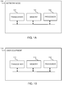
- Fig. 1A is a block diagram that illustrates a network node device 100 according to an example.
- Network node devices may include any device providing an air interface for user equipment to connect to a wireless network via multiple-access techniques, such as base stations including mMIMO access nodes.
- the network node device 100 comprises a radio transceiver 101 that is configured to receive one or more data sequences from a plurality of user equipment (including e.g. the user equipment 110 of FIG. 1B ) over a first set of resource elements and a second set of resource elements.
- the first set of resource elements is mapped non-orthogonally, and the second set of resource elements is mapped orthogonally.
- the uplink data resource elements (RE) in time and frequency may be divided into two sets of REs as follows.
- the first or common set of REs consists of time-frequency resources that may be shared by all users. That is, all users may utilize these resources to transmit their modulated data sequences.
- These uplink data resource elements are used via NOMA such that the data sequences will be separated in the spatial domain provided by a massive MIMO receiver.
- the second or user-specific set of REs consists of time-frequency resources that may be specific to each user. That is, all users are may be assigned non-overlapping time-frequency resources (e.g. via Frequency-Division Multiplexing (FDM) or Time-Division Multiplexing (TDM)), and/or Mutually Orthogonal Spreading Codes, such as Code-Division Multiplexing (CDM)) to orthogonally multiplex and transmit modulated data sequences over this second set of resources.
- FDM Frequency-Division Multiplexing
- TDM Time-Division Multiplexing
- CDM Code-Division Multiplexing
- This set of time-frequency REs carries users' data via Orthogonal Multiple-Access (OMA).
- OMA Orthogonal Multiple-Access
- FIG. 4A illustrates an example 410 of data multiplexing for two users over a coherence window (one coherence time * one coherence bandwidth) of a radio channel.
- FIG. 4B illustrates another example 420 for four users.
- FDM is used for the mapping of the data sequences in the user-specific set of the resources
- NOMA is used over the common set of REs.
- S cw the set of total resources over the coherence window is denoted as S cw where the cardinality of this set is
- T c ⁇ B c with T c and B c being, respectively, the number of resource elements in the time and frequency domains in the coherence window of the channel.
- the user-specific set is divided into K disjoint subsets to carry user-specific data sequences with orthogonal mapping.
- the same approach can be used for TDM or a combination of FDM and TDM to generate non-overlapping resource elements in the user-specific set of REs.
- Code-Division Multiplexing can be also used for orthogonal transmission of the data sequences mapped in the user-specific set of the resource elements since the channel is almost flat over the coherence window.
- FIG. 5 illustrates an example 510 of a blind multiple-access scheme for four users with mutual orthogonal spreading codes from a Hadamard matrix of size four in the user-specific set of the resource elements, and with NOMA without spreading in the common set of REs.
- each user may transmit one symbol spread over four REs so that in total one symbol/RE is transmitted in the user-specific set for the four users.
- the location of the user-specific set may be changed depending on the design to enable enhanced blind channel estimation.
- the common set of REs may be used by all users to transmit data without spreading via NOMA.
- the network node device 100 further comprises a processor 102 that is configured to determine channel vectors based on at least the data sequence received over the first set of resource elements or the second set of resource elements.
- the processor 102 is further configured to utilize the data sequence received over the second set of resource elements to associate the determined channel vectors with each of the plurality of user equipment.
- the processor 102 may be further configured to determine the channel vectors based on a scaled covariance matrix of the data sequence over at least one of the first set of resource elements and the second set of resource elements, determine eigenvalues and eigenvectors of the determined scaled covariance matrix, and scale the eigenvectors to obtain a candidate set of channel vectors.
- the following example illustrates that for large arrays the channel vectors are eigenvectors of the covariance matrix of the received data signal over the coherence interval.
- An example for two users is used for ease of illustration.
- the channel will be approximately constant over the coherence window of the radio channel that spans T c ⁇ B c , but the modulated data signals x 1 and x 2 are varying according to an i.i.d. (independent and identically distributed) distribution.
- the normalized covariance matrix may be calculated with respect to the data signals x i and additive white Gaussian noise (AWGN) in the coherence window as follows: where the above equation (4) follows from the signals x 1 , x 2 and z being mutually uncorrelated.
- AWGN additive white Gaussian noise
- the channel vectors of the users that are normalized by n t are approximately the eigenvector of the covariance matrix of the received signals over the coherence interval with the approximate eigenvalue ⁇ i P i which is the long-term channel gain multiplied by the transmit power.
- the candidate set of the channel vectors can be constructed as where K is number of the users.
- the scaling n t is added due to the norm of the eigenvector ⁇ i being one.
- the processor 102 may be further configured to perform the association of the channel vectors by determining correlations between the data sequence received over the second set of resource elements and the channel vectors in the obtained candidate set of channel vectors.
- the processor 102 may be further configured to perform the association of the channel vectors by determining normalized average received power of the data sequence received over the second set of resource elements, and selecting a channel vector in the obtained candidate set of channel vectors with eigenvalue closest to the determined normalized average received power.
- the user-specific received data that are orthogonally multiplexed using FDM, TDM or CDM may be used to identify which estimated channel belongs to which user.
- the set of estimated channel candidates for the two users is given by for which it is not known which one of the vectors respectively estimates the actual channel vectors h 1 and h 2 .
- ⁇ ji y d , j ⁇ v i ⁇ y d , j ⁇ ⁇ ⁇ v i ⁇
- the computation of ⁇ ji for large arrays shows a polarized behavior. That is, those eigenvectors that approximate the actual channel show a correlation close to one and the other eigenvectors show a correlation close to zero.
- the channel association can be done using this approach.
- the network node device 100 may determine that a member of the candidate set of channel estimates corresponds to the channel of a user if it gives the highest correlation to its user-specific received data.
- this value may be used to find the correct channel estimate in the candidate set if P j ⁇ j ⁇ P i , ⁇ i for all 1 ⁇ i, j ⁇ k and i ⁇ j.
- the correlation method may be used.
- the processor 102 may be further configured to determine the total number of resource elements in the first set of resource elements and the second set of resource elements based on radio channel coherence time and radio channel coherence bandwidth.
- the processor 102 may be configured to determine the number of resource elements in the second set of resource elements as the sum of uplink data layers transmitted from each of the plurality of user equipment.
- the processor 102 may be configured to determine the number of resource elements in the first set of resource elements as the difference between the total number of resource elements and the number of resource elements in the second set of resource elements.
- the processor 102 may be further configured to determine the first set of resource elements and the second set of resource elements based on information stored in the network node device.
- the network node device 100 may comprise a storage or a memory 103 that configured to store the information about the first set of resource elements and the second set of resource elements.
- the processor 102 may be further configured to cause the transceiver to send the information about the determined first and second sets of resource elements to the plurality of user equipment.
- Fig. 1B is a block diagram illustrating user equipment 110 according to an example.
- User equipment may include various types of devices used by an end user entity and capable of communication in a wireless network. Such devices include but are not limited to smartphones, tablet computers, smart watches, lap top computers, Internet-of-Things (IoT) devices, and the like.
- IoT Internet-of-Things
- the user equipment 110 comprises a processor 112 that is configured to access a resource element assignment of a first set of resource elements and a second set of resource elements.
- the first set of resource elements is mapped non-orthogonally and the second set of resource elements is mapped orthogonally.
- the user equipment 110 further comprises a radio transceiver 111 that is configured to transmit a data sequence to a network node device (such as the network node device 100 of FIG. 1A ) over the first set of resource elements and over the second set of resource elements.
- a network node device such as the network node device 100 of FIG. 1A
- the user equipment 110 may further comprise a storage or a memory 113 that is configured to store the resource element assignment.
- the radio transceiver 111 may be further configured to receive the resource element assignment from the network node device (such as the network node device 100 of FIG. 1A ).
- UE-specific and antenna-port specific data may be transmitted such that the uplink data over the second set at different antenna ports for each UE are also orthogonally multiplexed.
- a whitening filter based on the correlation matrix at the UE side can be used prior to the transmission at the UE side. This way the effective channel at the network node device appears orthogonal and the same procedure can be used to blindly estimate the channels.
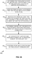
- FIG. 2A is a flow chart illustrating a method 200 according to an example.
- the network node device may comprise the network node device 100 of FIG. 1A .
- the user equipment may comprise the user equipment 110 of FIG. 1B .
- a network node device may determine a first set of resource elements and a second set of resource elements.
- the first set of resource elements is mapped non-orthogonally and the second set of resource elements is mapped orthogonally.
- the network node device may determine the first set of resource elements and the second set of resource elements based on information stored in the network node device.
- the network node device may determine the total number of resource elements in the first set of resource elements and the second set of resource elements based on radio channel coherence time and radio channel coherence bandwidth. For example, as discussed in connection with FIG. 1A , the network node device may determine the total number of resource elements in the first set of resource elements and the second set of resource elements based on the channel coherence time T c and coherence bandwidth B c of the radio channels, such that the total number of REs in the two sets is less than or equal to the product of T c and B c .
- the network node device may determine the number of resource elements in the second set of resource elements as the sum of uplink data layers transmitted from each of the plurality of user equipment. For example, as discussed in connection with FIG. 1A , the network node device may determine the number of resource elements in the second set of resource elements (i.e. for orthogonal multiple-access (OMA)) as equal to the number of users (for single-antenna UEs) or as the sum of uplink data layers transmitted from all the UEs. Furthermore, the network node device may determine the number of resource elements in the first set of resource elements as the difference between the total number of resource elements and the number of resource elements in the second set of resource elements. In other words, the number of REs for the NOMA set may equal the total number of REs minus the number of REs used for the OMA set.
- OMA orthogonal multiple-access
- the network node device may send information about the determined first and second sets of resource elements to the plurality of user equipment.
- the network node device receives one or more data sequences from a plurality of user equipment over the first set of resource elements and the second set of resource elements.
- the first set of resource elements is mapped non-orthogonally and the second set of resource elements is mapped orthogonally.
- the network node device determines channel vectors based at least on the data sequence (s) received over the first set of resource elements or the second set of resource elements.
- the network node device utilizes the data sequence(s) received over the second set of resource elements to associate the determined channel vectors with each of the plurality of user equipment.
- the network node device may perform e.g. uplink data detection (e.g. using MF (Matched Filtering) or ZF (Zero-Forcing) filters) and/or precoding of downlink data sequences using the estimated spatial channels.
- uplink data detection e.g. using MF (Matched Filtering) or ZF (Zero-Forcing) filters
- precoding e.g. using MF (Matched Filtering) or ZF (Zero-Forcing) filters
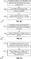
- Fig. 2B is a flow chart illustrating a method 210 according to an example.
- the method 210 may be an example implementation of operation 204 of FIG. 2A .
- the network node device may determine the channel vectors based on a scaled covariance matrix of the data sequence over at least one of the first set of resource elements and the second set of resource elements.
- the network node device may determine eigenvalues and eigenvectors of the determined scaled covariance matrix.
- the network node device may scale the eigenvectors to obtain a candidate set of channel vectors.
- Fig. 2C is a flow chart illustrating a method 220 according to an example.
- the method 220 may be an example implementation of operation 205 of FIG. 2A .
- the network node device may determine correlations between the data sequence received over the second set of resource elements and the channel vectors in the obtained candidate set of channel vectors.
- the network node device may select candidate channel vector with highest correlation to the data sequence received over the second set of resource elements.
- Fig. 2D is a flow chart illustrating a method 230 according to an example.
- the method 230 may be an example implementation of operation 205 of FIG. 2A .
- the network node device may determine normalized average received power of the data sequence received over the second set of resource elements.
- the network node device may select a channel vector in the obtained candidate set of channel vectors with eigenvalue closest to the determined normalized average received power.
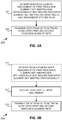
- Fig. 3A is a flow chart illustrating a method 300 according to an example.
- a user equipment accesses a resource element assignment (i.e. mapping) of a first set of resource elements and a second set of resource elements.
- the first set of resource elements is mapped non-orthogonally and the second set of resource elements is mapped orthogonally.
- the resource element assignment has been stored in the user equipment.
- the user equipment transmits one or more data sequences to a network node device over the first set of resource elements and over the second set of resource elements.
- Fig. 3B is a flow chart illustrating a method according to an example.
- a user equipment receives a resource element assignment (i.e. mapping) of a first set of resource elements and a second set of resource elements from a network node device.
- the first set of resource elements is mapped non-orthogonally and the second set of re-source elements is mapped orthogonally.
- the received resource element assignment may then be stored in the user equipment.
- the user equipment accesses the resource element assignment of the first set of resource elements and the second set of resource elements.
- the user equipment transmits one or more data sequences to a network node device over the first set of resource elements and over the second set of resource elements.
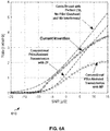
- the estimated channels in the scheme according to the disclosed approach are mutually orthogonal since they are the eigenvectors of a semi-definite matrix and hence ZF does not improve the rate for this case. In other words, the disclosed approach finds estimates of the channel vectors that are mutually orthogonal.
- the degradation of the disclosed approach in high SNR is due to the fact that the covariance matrix is only computed for 82 samples which is a low number to approximate a large covariance matrix of size n t ⁇ n t .
- the high-SNR scenarios normally occur for low-mobility users whose radio channels have a much longer coherence interval and hence for these cases the covariance matrix can be better approximated.
- Another way to improve the result is to use larger antenna arrays since equation (6) becomes more accurate for larger arrays.
- the functionality described herein can be performed, at least in part, by one or more computer program product components such as software components.
- the user equipment 110 and/or network node device 100 comprise a processor configured by program code to execute the embodiments of the operations and functionality described.
- the functionality described herein can be performed, at least in part, by one or more hardware logic components.
- illustrative types of hardware logic components include Field-programmable Gate Arrays (FPGAs), Program-specific Integrated Circuits (ASICs), Program-specific Standard Products (ASSPs), System-on-a-chip systems (SOCs), Complex Programmable Logic Devices (CPLDs), and Graphics Processing Units (GPUs).
Landscapes
- Engineering & Computer Science (AREA)
- Signal Processing (AREA)
- Computer Networks & Wireless Communication (AREA)
- Power Engineering (AREA)
- Quality & Reliability (AREA)
- Mobile Radio Communication Systems (AREA)
- Physics & Mathematics (AREA)
- Electromagnetism (AREA)
Claims (9)
- Dispositif de nœud de réseau (100), comprenant :un émetteur-récepteur radio (101) conçu pour recevoir une séquence de données d'une pluralité d'équipements utilisateur sur un premier ensemble d'éléments de ressources et un second ensemble d'éléments de ressources, dans lequel le premier ensemble d'éléments de ressources est mappé de manière non orthogonale et le second ensemble d'éléments de ressources est mappé de manière orthogonale ; etun processeur (102) conçu pour :- déterminer les vecteurs de canal sur la base d'au moins la séquence de données reçue sur le premier ensemble d'éléments de ressources ou le second ensemble d'éléments de ressources,- utiliser la séquence de données reçue sur le second ensemble d'éléments de ressources pour associer les vecteurs de canal déterminés à chacun de la pluralité d'équipements utilisateur ; etdans lequel le processeur (102) est en outre conçu pour déterminer les vecteurs de canal sur la base d'une matrice de covariance mise à l'échelle de la séquence de données sur au moins l'un du premier ensemble d'éléments de ressources et du second ensemble d'éléments de ressources, déterminer les valeurs propres et les vecteurs propres de la matrice de covariance mise à l'échelle déterminée et mettre à l'échelle les vecteurs propres pour obtenir un ensemble candidat de vecteurs de canal.
- Dispositif de nœud de réseau (100) selon la revendication 1, dans lequel le processeur (102) est en outre conçu pour effectuer l'association des vecteurs de canal en déterminant des corrélations entre la séquence de données reçue sur le second ensemble d'éléments de ressources et les vecteurs de canal dans l'ensemble candidat obtenu de vecteurs de canal.
- Dispositif de nœud de réseau (100) selon la revendication 1, dans lequel le processeur (102) est en outre conçu pour effectuer l'association des vecteurs de canal en : déterminant la puissance reçue moyenne normalisée de la séquence de données reçue sur le second ensemble d'éléments de ressources, et sélectionnant un vecteur de canal dans l'ensemble candidat obtenu de vecteurs de canal avec une valeur propre la plus proche de la puissance reçue moyenne normalisée déterminée.
- Dispositif de nœud de réseau (100) selon l'une quelconque des revendications 1 à 3, dans lequel le processeur (102) est en outre conçu pour déterminer le nombre total d'éléments de ressources dans le premier ensemble d'éléments de ressources et le second ensemble d'éléments de ressources sur la base du temps de cohérence du canal radio et de la largeur de bande de cohérence du canal radio.
- Dispositif de nœud de réseau (100) selon la revendication 4, dans lequel le processeur (102) est en outre conçu pour déterminer le nombre d'éléments de ressources dans le second ensemble d'éléments de ressources comme la somme des couches de données de liaison montante transmises par chacun de la pluralité d'équipements utilisateur, et le processeur (102) est en outre conçu pour déterminer le nombre d'éléments de ressources dans le premier ensemble d'éléments de ressources comme la différence entre le nombre total d'éléments de ressources et le nombre d'éléments de ressources dans le second ensemble d'éléments de ressources.
- Dispositif de nœud de réseau (100) selon l'une quelconque des revendications 1 à 5, dans lequel le processeur (102) est en outre conçu pour amener l'émetteur-récepteur (101) à envoyer des informations sur des premier et second ensembles déterminés d'éléments de ressources à la pluralité d'équipements utilisateur.
- Dispositif de nœud de réseau (100) selon l'une quelconque des revendications 1 à 6, dans lequel le processeur (102) est en outre conçu pour déterminer le premier ensemble d'éléments de ressources et le second ensemble d'éléments de ressources sur la base des informations stockées dans le dispositif de nœud de réseau (100).
- Procédé (200), comprenant :la réception (203), par un dispositif de nœud de réseau, d'une séquence de données d'une pluralité d'équipements utilisateur sur un premier ensemble d'éléments de ressources et un second ensemble d'éléments de ressources, dans lequel le premier ensemble d'éléments de ressources est mappé de manière non orthogonale et le second ensemble d'éléments de ressources est mappé de manière orthogonale ;la détermination (204), par le dispositif de nœud de réseau, de vecteurs de canal sur la base d'au moins la séquence de données reçue sur le premier ensemble d'éléments de ressources ou le second ensemble d'éléments de ressources ;l'utilisation (205), par le dispositif de nœud de réseau, de la séquence de données reçue sur le second ensemble d'éléments de ressources pour associer les vecteurs de canal déterminés à chacun de la pluralité d'équipements utilisateur ; etdans lequel le procédé comprend en outre : la détermination, par le dispositif de nœud de réseau, des vecteurs de canal sur la base d'une matrice de covariance mise à l'échelle de la séquence de données sur au moins l'un du premier ensemble d'éléments de ressources et du second ensemble d'éléments de ressources ; la détermination, par le dispositif de nœud de réseau, des valeurs propres et des vecteurs propres de la matrice de covariance mise à l'échelle déterminée ; et la mise à l'échelle, par le dispositif de nœud de réseau, des vecteurs propres pour obtenir un ensemble candidat de vecteurs de canal.
- Programme informatique comprenant un code de programme conçu pour exécuter un procédé selon la revendication 8, lorsque le programme informatique est exécuté sur un ordinateur.
Applications Claiming Priority (1)
| Application Number | Priority Date | Filing Date | Title |
|---|---|---|---|
| PCT/EP2016/077304 WO2018086696A1 (fr) | 2016-11-10 | 2016-11-10 | Dispositifs, procédés et programmes informatiques de communication sans fil à accès multiple |
Publications (2)
| Publication Number | Publication Date |
|---|---|
| EP3529926A1 EP3529926A1 (fr) | 2019-08-28 |
| EP3529926B1 true EP3529926B1 (fr) | 2021-08-04 |
Family
ID=57321297
Family Applications (1)
| Application Number | Title | Priority Date | Filing Date |
|---|---|---|---|
| EP16795301.7A Active EP3529926B1 (fr) | 2016-11-10 | 2016-11-10 | Dispositifs, procédés et programmes informatiques de communication sans fil à accès multiple |
Country Status (4)
| Country | Link |
|---|---|
| US (1) | US10972234B2 (fr) |
| EP (1) | EP3529926B1 (fr) |
| CN (2) | CN109661786B (fr) |
| WO (1) | WO2018086696A1 (fr) |
Families Citing this family (5)
| Publication number | Priority date | Publication date | Assignee | Title |
|---|---|---|---|---|
| US11329848B2 (en) | 2018-06-13 | 2022-05-10 | Cohere Technologies, Inc. | Reciprocal calibration for channel estimation based on second-order statistics |
| US11159420B2 (en) * | 2019-04-17 | 2021-10-26 | Cloudflare, Inc. | Method and apparatus of automatic route optimization in a private virtual network for client devices of a local network |
| US11825462B2 (en) * | 2019-12-20 | 2023-11-21 | Qualcomm Incorporated | Methods and apparatus for sequence design based on subsampling |
| EP4104158A4 (fr) * | 2020-04-21 | 2023-08-09 | Zeku, Inc. | Architecture évolutive de plan de données pour une communication sans fil |
| WO2025105522A1 (fr) * | 2023-11-14 | 2025-05-22 | 삼성전자 주식회사 | Procédé et appareil de gestion de ressources pour un accès multiple sans licence dans un système de communication sans fil |
Family Cites Families (16)
| Publication number | Priority date | Publication date | Assignee | Title |
|---|---|---|---|---|
| JP5864200B2 (ja) * | 2011-05-20 | 2016-02-17 | 株式会社Nttドコモ | 受信装置、送信装置及び無線通信方法 |
| US20140198761A1 (en) * | 2011-08-12 | 2014-07-17 | Nokia Solutions And Networks Oy | Resource Reconfiguration for Up-Link Transmission |
| US9276729B2 (en) * | 2012-12-07 | 2016-03-01 | Intel Deutschland Gmbh | Determination of a noise and interference covariance measure |
| CN105874724B (zh) * | 2013-12-13 | 2019-04-12 | 华为技术有限公司 | 上行解调参考信号传输方法和装置 |
| WO2015131393A1 (fr) * | 2014-03-07 | 2015-09-11 | Telefonaktiebolaget L M Ericsson (Publ) | Procédé et dispositif de calcul de la puissance reçue d'un signal de référence |
| WO2015149812A1 (fr) * | 2014-04-01 | 2015-10-08 | Aalborg Universitet | Décontamination de pilote par l'intermédiaire d'un saut de séquence pilote dans des systèmes mimo massifs |
| US10003486B2 (en) * | 2014-04-28 | 2018-06-19 | Intel IP Corporation | Non-orthogonal multiple access (NOMA) wireless systems and methods |
| WO2016064246A1 (fr) * | 2014-10-24 | 2016-04-28 | Samsung Electronics Co., Ltd. | Quantificateur vectoriel efficace pour systèmes fd-mimo |
| CN105634654B (zh) * | 2014-10-27 | 2019-12-17 | 中兴通讯股份有限公司 | 多用户信息传输的叠加编码、解调方法及装置 |
| WO2016085443A1 (fr) * | 2014-11-24 | 2016-06-02 | Hewlett Packard Enterprise Development Lp | Gestion d'application sur la base de corrélations de données |
| CN105634702B (zh) * | 2014-12-01 | 2019-09-10 | 中兴通讯股份有限公司 | 多用户信息共道发送、接收方法及其装置 |
| US10390292B2 (en) * | 2015-03-26 | 2019-08-20 | Intel IP Corporation | Device, system and method of quasi-orthogonal multiple access |
| US10536249B2 (en) * | 2015-10-15 | 2020-01-14 | Ntt Docomo, Inc. | Uplink pilot reuse and user-proximity detection in wireless networks |
| WO2017139005A1 (fr) * | 2016-02-09 | 2017-08-17 | Intel IP Corporation | Options d'étalement destinées à un accès multiple non-orthogonal |
| WO2017193056A1 (fr) * | 2016-05-05 | 2017-11-09 | Ntt Docomo, Inc. | Mécanisme et procédure de sélection de station de base basée sur une détection de pilote de liaison montante et de proximité d'utilisateur distribuée |
| KR102449472B1 (ko) * | 2016-11-03 | 2022-10-11 | 삼성전자 주식회사 | 무선 통신 시스템에서 단말 간 간섭 관리 방법 및 장치 |
-
2016
- 2016-11-10 CN CN201680088951.6A patent/CN109661786B/zh active Active
- 2016-11-10 CN CN202010218482.3A patent/CN111556570B/zh active Active
- 2016-11-10 WO PCT/EP2016/077304 patent/WO2018086696A1/fr not_active Ceased
- 2016-11-10 EP EP16795301.7A patent/EP3529926B1/fr active Active
-
2019
- 2019-05-10 US US16/408,803 patent/US10972234B2/en active Active
Also Published As
| Publication number | Publication date |
|---|---|
| CN109661786B (zh) | 2020-04-14 |
| US10972234B2 (en) | 2021-04-06 |
| CN111556570A (zh) | 2020-08-18 |
| CN111556570B (zh) | 2024-05-14 |
| CN109661786A (zh) | 2019-04-19 |
| US20190268116A1 (en) | 2019-08-29 |
| EP3529926A1 (fr) | 2019-08-28 |
| WO2018086696A1 (fr) | 2018-05-17 |
Similar Documents
| Publication | Publication Date | Title |
|---|---|---|
| US10972234B2 (en) | Devices, methods and computer programs for wireless communication with multiple-access | |
| Jiang et al. | A framework for over-the-air reciprocity calibration for TDD massive MIMO systems | |
| US12101205B2 (en) | Method and apparatus for improving multi-user multiplexing performance, device, and storage medium | |
| EP3148145B1 (fr) | Procédé et dispositif d'allocation de ressource | |
| CN101877689B (zh) | 数据发送处理方法与装置、数据接收处理方法与装置 | |
| KR102034591B1 (ko) | Mimo 송신기가 사용자를 위한 자원을 할당하는 방법 및 자원을 이용해 데이터를 전송할 사용자를 스케쥴링하는 방법 | |
| US20150098444A1 (en) | Large scale antenna system with overlaying small cells | |
| US9148314B2 (en) | Interference cancellation in wireless OFDMA with MIMO spatial multiplexing | |
| CN104105120A (zh) | 一种干扰测量方法、网络侧设备及终端设备 | |
| JP2008306713A (ja) | サブチャネル割当装置 | |
| WO2013039248A1 (fr) | Procédé de communication sans fil et dispositif de station de base | |
| Tsinos et al. | Blind opportunistic interference alignment in MIMO cognitive radio systems | |
| CN102100045B (zh) | 数据发送处理方法与装置、数据接收处理方法与装置 | |
| Elijah et al. | Mitigating pilot contamination in massive MIMO system—5G: An overview | |
| Mirzaei et al. | Semi-blind time-domain channel estimation for frequency-selective multiuser massive MIMO systems | |
| Bogale et al. | Pilot contamination mitigation for wideband massive MMO: Number of cells vs multipath | |
| EP3136802B1 (fr) | Procédé et appareil de configuration de pilote | |
| Salh et al. | Mitigated pilot contamination to achieve higher downlink data rate in 5G massive MIMO systems | |
| Garg et al. | Partially loaded superimposed training scheme for large MIMO uplink systems | |
| EP3529960B1 (fr) | Générateur de séquences pilotes et procédé et estimateur de canal correspondants et procédé correspondant | |
| Wang et al. | A temporal domain based method against pilot contamination for multi-cell massive MIMO systems | |
| Shen et al. | User capacity of pilot-contaminated TDD massive MIMO systems | |
| Sleem et al. | Pilot-free transmission in 3GPP OFDM MIMO systems via canonical correlation | |
| Luo et al. | Pilot decontamination via PDP alignment | |
| Sabbagh et al. | Pilot allocation and sum-rate analysis in distributed massive MIMO systems |
Legal Events
| Date | Code | Title | Description |
|---|---|---|---|
| STAA | Information on the status of an ep patent application or granted ep patent |
Free format text: STATUS: UNKNOWN |
|
| STAA | Information on the status of an ep patent application or granted ep patent |
Free format text: STATUS: THE INTERNATIONAL PUBLICATION HAS BEEN MADE |
|
| PUAI | Public reference made under article 153(3) epc to a published international application that has entered the european phase |
Free format text: ORIGINAL CODE: 0009012 |
|
| STAA | Information on the status of an ep patent application or granted ep patent |
Free format text: STATUS: REQUEST FOR EXAMINATION WAS MADE |
|
| 17P | Request for examination filed |
Effective date: 20190522 |
|
| AK | Designated contracting states |
Kind code of ref document: A1 Designated state(s): AL AT BE BG CH CY CZ DE DK EE ES FI FR GB GR HR HU IE IS IT LI LT LU LV MC MK MT NL NO PL PT RO RS SE SI SK SM TR |
|
| AX | Request for extension of the european patent |
Extension state: BA ME |
|
| DAV | Request for validation of the european patent (deleted) | ||
| DAX | Request for extension of the european patent (deleted) | ||
| GRAP | Despatch of communication of intention to grant a patent |
Free format text: ORIGINAL CODE: EPIDOSNIGR1 |
|
| STAA | Information on the status of an ep patent application or granted ep patent |
Free format text: STATUS: GRANT OF PATENT IS INTENDED |
|
| INTG | Intention to grant announced |
Effective date: 20210316 |
|
| GRAS | Grant fee paid |
Free format text: ORIGINAL CODE: EPIDOSNIGR3 |
|
| GRAA | (expected) grant |
Free format text: ORIGINAL CODE: 0009210 |
|
| STAA | Information on the status of an ep patent application or granted ep patent |
Free format text: STATUS: THE PATENT HAS BEEN GRANTED |
|
| AK | Designated contracting states |
Kind code of ref document: B1 Designated state(s): AL AT BE BG CH CY CZ DE DK EE ES FI FR GB GR HR HU IE IS IT LI LT LU LV MC MK MT NL NO PL PT RO RS SE SI SK SM TR |
|
| REG | Reference to a national code |
Ref country code: GB Ref legal event code: FG4D |
|
| REG | Reference to a national code |
Ref country code: AT Ref legal event code: REF Ref document number: 1418076 Country of ref document: AT Kind code of ref document: T Effective date: 20210815 |
|
| REG | Reference to a national code |
Ref country code: CH Ref legal event code: EP |
|
| REG | Reference to a national code |
Ref country code: DE Ref legal event code: R096 Ref document number: 602016061665 Country of ref document: DE |
|
| REG | Reference to a national code |
Ref country code: IE Ref legal event code: FG4D |
|
| REG | Reference to a national code |
Ref country code: LT Ref legal event code: MG9D |
|
| REG | Reference to a national code |
Ref country code: NL Ref legal event code: MP Effective date: 20210804 |
|
| REG | Reference to a national code |
Ref country code: AT Ref legal event code: MK05 Ref document number: 1418076 Country of ref document: AT Kind code of ref document: T Effective date: 20210804 |
|
| PG25 | Lapsed in a contracting state [announced via postgrant information from national office to epo] |
Ref country code: NO Free format text: LAPSE BECAUSE OF FAILURE TO SUBMIT A TRANSLATION OF THE DESCRIPTION OR TO PAY THE FEE WITHIN THE PRESCRIBED TIME-LIMIT Effective date: 20211104 Ref country code: PT Free format text: LAPSE BECAUSE OF FAILURE TO SUBMIT A TRANSLATION OF THE DESCRIPTION OR TO PAY THE FEE WITHIN THE PRESCRIBED TIME-LIMIT Effective date: 20211206 Ref country code: FI Free format text: LAPSE BECAUSE OF FAILURE TO SUBMIT A TRANSLATION OF THE DESCRIPTION OR TO PAY THE FEE WITHIN THE PRESCRIBED TIME-LIMIT Effective date: 20210804 Ref country code: ES Free format text: LAPSE BECAUSE OF FAILURE TO SUBMIT A TRANSLATION OF THE DESCRIPTION OR TO PAY THE FEE WITHIN THE PRESCRIBED TIME-LIMIT Effective date: 20210804 Ref country code: HR Free format text: LAPSE BECAUSE OF FAILURE TO SUBMIT A TRANSLATION OF THE DESCRIPTION OR TO PAY THE FEE WITHIN THE PRESCRIBED TIME-LIMIT Effective date: 20210804 Ref country code: LT Free format text: LAPSE BECAUSE OF FAILURE TO SUBMIT A TRANSLATION OF THE DESCRIPTION OR TO PAY THE FEE WITHIN THE PRESCRIBED TIME-LIMIT Effective date: 20210804 Ref country code: BG Free format text: LAPSE BECAUSE OF FAILURE TO SUBMIT A TRANSLATION OF THE DESCRIPTION OR TO PAY THE FEE WITHIN THE PRESCRIBED TIME-LIMIT Effective date: 20211104 Ref country code: AT Free format text: LAPSE BECAUSE OF FAILURE TO SUBMIT A TRANSLATION OF THE DESCRIPTION OR TO PAY THE FEE WITHIN THE PRESCRIBED TIME-LIMIT Effective date: 20210804 Ref country code: RS Free format text: LAPSE BECAUSE OF FAILURE TO SUBMIT A TRANSLATION OF THE DESCRIPTION OR TO PAY THE FEE WITHIN THE PRESCRIBED TIME-LIMIT Effective date: 20210804 Ref country code: SE Free format text: LAPSE BECAUSE OF FAILURE TO SUBMIT A TRANSLATION OF THE DESCRIPTION OR TO PAY THE FEE WITHIN THE PRESCRIBED TIME-LIMIT Effective date: 20210804 |
|
| PG25 | Lapsed in a contracting state [announced via postgrant information from national office to epo] |
Ref country code: PL Free format text: LAPSE BECAUSE OF FAILURE TO SUBMIT A TRANSLATION OF THE DESCRIPTION OR TO PAY THE FEE WITHIN THE PRESCRIBED TIME-LIMIT Effective date: 20210804 Ref country code: LV Free format text: LAPSE BECAUSE OF FAILURE TO SUBMIT A TRANSLATION OF THE DESCRIPTION OR TO PAY THE FEE WITHIN THE PRESCRIBED TIME-LIMIT Effective date: 20210804 Ref country code: GR Free format text: LAPSE BECAUSE OF FAILURE TO SUBMIT A TRANSLATION OF THE DESCRIPTION OR TO PAY THE FEE WITHIN THE PRESCRIBED TIME-LIMIT Effective date: 20211105 |
|
| PG25 | Lapsed in a contracting state [announced via postgrant information from national office to epo] |
Ref country code: NL Free format text: LAPSE BECAUSE OF FAILURE TO SUBMIT A TRANSLATION OF THE DESCRIPTION OR TO PAY THE FEE WITHIN THE PRESCRIBED TIME-LIMIT Effective date: 20210804 |
|
| PG25 | Lapsed in a contracting state [announced via postgrant information from national office to epo] |
Ref country code: DK Free format text: LAPSE BECAUSE OF FAILURE TO SUBMIT A TRANSLATION OF THE DESCRIPTION OR TO PAY THE FEE WITHIN THE PRESCRIBED TIME-LIMIT Effective date: 20210804 |
|
| REG | Reference to a national code |
Ref country code: DE Ref legal event code: R097 Ref document number: 602016061665 Country of ref document: DE |
|
| PG25 | Lapsed in a contracting state [announced via postgrant information from national office to epo] |
Ref country code: SM Free format text: LAPSE BECAUSE OF FAILURE TO SUBMIT A TRANSLATION OF THE DESCRIPTION OR TO PAY THE FEE WITHIN THE PRESCRIBED TIME-LIMIT Effective date: 20210804 Ref country code: SK Free format text: LAPSE BECAUSE OF FAILURE TO SUBMIT A TRANSLATION OF THE DESCRIPTION OR TO PAY THE FEE WITHIN THE PRESCRIBED TIME-LIMIT Effective date: 20210804 Ref country code: RO Free format text: LAPSE BECAUSE OF FAILURE TO SUBMIT A TRANSLATION OF THE DESCRIPTION OR TO PAY THE FEE WITHIN THE PRESCRIBED TIME-LIMIT Effective date: 20210804 Ref country code: EE Free format text: LAPSE BECAUSE OF FAILURE TO SUBMIT A TRANSLATION OF THE DESCRIPTION OR TO PAY THE FEE WITHIN THE PRESCRIBED TIME-LIMIT Effective date: 20210804 Ref country code: CZ Free format text: LAPSE BECAUSE OF FAILURE TO SUBMIT A TRANSLATION OF THE DESCRIPTION OR TO PAY THE FEE WITHIN THE PRESCRIBED TIME-LIMIT Effective date: 20210804 Ref country code: AL Free format text: LAPSE BECAUSE OF FAILURE TO SUBMIT A TRANSLATION OF THE DESCRIPTION OR TO PAY THE FEE WITHIN THE PRESCRIBED TIME-LIMIT Effective date: 20210804 |
|
| PLBE | No opposition filed within time limit |
Free format text: ORIGINAL CODE: 0009261 |
|
| STAA | Information on the status of an ep patent application or granted ep patent |
Free format text: STATUS: NO OPPOSITION FILED WITHIN TIME LIMIT |
|
| PG25 | Lapsed in a contracting state [announced via postgrant information from national office to epo] |
Ref country code: MC Free format text: LAPSE BECAUSE OF FAILURE TO SUBMIT A TRANSLATION OF THE DESCRIPTION OR TO PAY THE FEE WITHIN THE PRESCRIBED TIME-LIMIT Effective date: 20210804 |
|
| REG | Reference to a national code |
Ref country code: CH Ref legal event code: PL |
|
| 26N | No opposition filed |
Effective date: 20220506 |
|
| GBPC | Gb: european patent ceased through non-payment of renewal fee |
Effective date: 20211110 |
|
| PG25 | Lapsed in a contracting state [announced via postgrant information from national office to epo] |
Ref country code: LU Free format text: LAPSE BECAUSE OF NON-PAYMENT OF DUE FEES Effective date: 20211110 Ref country code: IT Free format text: LAPSE BECAUSE OF FAILURE TO SUBMIT A TRANSLATION OF THE DESCRIPTION OR TO PAY THE FEE WITHIN THE PRESCRIBED TIME-LIMIT Effective date: 20210804 Ref country code: BE Free format text: LAPSE BECAUSE OF NON-PAYMENT OF DUE FEES Effective date: 20211130 |
|
| REG | Reference to a national code |
Ref country code: BE Ref legal event code: MM Effective date: 20211130 |
|
| PG25 | Lapsed in a contracting state [announced via postgrant information from national office to epo] |
Ref country code: SI Free format text: LAPSE BECAUSE OF FAILURE TO SUBMIT A TRANSLATION OF THE DESCRIPTION OR TO PAY THE FEE WITHIN THE PRESCRIBED TIME-LIMIT Effective date: 20210804 Ref country code: LI Free format text: LAPSE BECAUSE OF NON-PAYMENT OF DUE FEES Effective date: 20211130 Ref country code: CH Free format text: LAPSE BECAUSE OF NON-PAYMENT OF DUE FEES Effective date: 20211130 |
|
| PG25 | Lapsed in a contracting state [announced via postgrant information from national office to epo] |
Ref country code: IE Free format text: LAPSE BECAUSE OF NON-PAYMENT OF DUE FEES Effective date: 20211110 Ref country code: GB Free format text: LAPSE BECAUSE OF NON-PAYMENT OF DUE FEES Effective date: 20211110 |
|
| PG25 | Lapsed in a contracting state [announced via postgrant information from national office to epo] |
Ref country code: FR Free format text: LAPSE BECAUSE OF NON-PAYMENT OF DUE FEES Effective date: 20211130 |
|
| PG25 | Lapsed in a contracting state [announced via postgrant information from national office to epo] |
Ref country code: CY Free format text: LAPSE BECAUSE OF FAILURE TO SUBMIT A TRANSLATION OF THE DESCRIPTION OR TO PAY THE FEE WITHIN THE PRESCRIBED TIME-LIMIT Effective date: 20210804 |
|
| PG25 | Lapsed in a contracting state [announced via postgrant information from national office to epo] |
Ref country code: HU Free format text: LAPSE BECAUSE OF FAILURE TO SUBMIT A TRANSLATION OF THE DESCRIPTION OR TO PAY THE FEE WITHIN THE PRESCRIBED TIME-LIMIT; INVALID AB INITIO Effective date: 20161110 |
|
| PG25 | Lapsed in a contracting state [announced via postgrant information from national office to epo] |
Ref country code: MK Free format text: LAPSE BECAUSE OF FAILURE TO SUBMIT A TRANSLATION OF THE DESCRIPTION OR TO PAY THE FEE WITHIN THE PRESCRIBED TIME-LIMIT Effective date: 20210804 |
|
| PG25 | Lapsed in a contracting state [announced via postgrant information from national office to epo] |
Ref country code: MT Free format text: LAPSE BECAUSE OF FAILURE TO SUBMIT A TRANSLATION OF THE DESCRIPTION OR TO PAY THE FEE WITHIN THE PRESCRIBED TIME-LIMIT Effective date: 20210804 |
|
| PG25 | Lapsed in a contracting state [announced via postgrant information from national office to epo] |
Ref country code: TR Free format text: LAPSE BECAUSE OF FAILURE TO SUBMIT A TRANSLATION OF THE DESCRIPTION OR TO PAY THE FEE WITHIN THE PRESCRIBED TIME-LIMIT Effective date: 20210804 |
|
| PGFP | Annual fee paid to national office [announced via postgrant information from national office to epo] |
Ref country code: DE Payment date: 20250930 Year of fee payment: 10 |