EP3529929B1 - Verfahren und vorrichtung zum multiplexing von kanalstatusinformationen - Google Patents
Verfahren und vorrichtung zum multiplexing von kanalstatusinformationen Download PDFInfo
- Publication number
- EP3529929B1 EP3529929B1 EP17880781.4A EP17880781A EP3529929B1 EP 3529929 B1 EP3529929 B1 EP 3529929B1 EP 17880781 A EP17880781 A EP 17880781A EP 3529929 B1 EP3529929 B1 EP 3529929B1
- Authority
- EP
- European Patent Office
- Prior art keywords
- csi
- csi part
- pmi
- reporting
- cqi
- Prior art date
- Legal status (The legal status is an assumption and is not a legal conclusion. Google has not performed a legal analysis and makes no representation as to the accuracy of the status listed.)
- Active
Links
Images






Classifications
-
- H—ELECTRICITY
- H04—ELECTRIC COMMUNICATION TECHNIQUE
- H04L—TRANSMISSION OF DIGITAL INFORMATION, e.g. TELEGRAPHIC COMMUNICATION
- H04L1/00—Arrangements for detecting or preventing errors in the information received
- H04L1/0001—Systems modifying transmission characteristics according to link quality, e.g. power backoff
- H04L1/0023—Systems modifying transmission characteristics according to link quality, e.g. power backoff characterised by the signalling
- H04L1/0026—Transmission of channel quality indication
-
- H—ELECTRICITY
- H04—ELECTRIC COMMUNICATION TECHNIQUE
- H04L—TRANSMISSION OF DIGITAL INFORMATION, e.g. TELEGRAPHIC COMMUNICATION
- H04L5/00—Arrangements affording multiple use of the transmission path
- H04L5/003—Arrangements for allocating sub-channels of the transmission path
- H04L5/0053—Allocation of signalling, i.e. of overhead other than pilot signals
-
- H—ELECTRICITY
- H04—ELECTRIC COMMUNICATION TECHNIQUE
- H04B—TRANSMISSION
- H04B7/00—Radio transmission systems, i.e. using radiation field
- H04B7/02—Diversity systems; Multi-antenna system, i.e. transmission or reception using multiple antennas
- H04B7/04—Diversity systems; Multi-antenna system, i.e. transmission or reception using multiple antennas using two or more spaced independent antennas
- H04B7/0413—MIMO systems
- H04B7/0417—Feedback systems
-
- H—ELECTRICITY
- H04—ELECTRIC COMMUNICATION TECHNIQUE
- H04B—TRANSMISSION
- H04B7/00—Radio transmission systems, i.e. using radiation field
- H04B7/02—Diversity systems; Multi-antenna system, i.e. transmission or reception using multiple antennas
- H04B7/04—Diversity systems; Multi-antenna system, i.e. transmission or reception using multiple antennas using two or more spaced independent antennas
- H04B7/0413—MIMO systems
- H04B7/0456—Selection of precoding matrices or codebooks, e.g. using matrices antenna weighting
- H04B7/0478—Special codebook structures directed to feedback optimisation
-
- H—ELECTRICITY
- H04—ELECTRIC COMMUNICATION TECHNIQUE
- H04B—TRANSMISSION
- H04B7/00—Radio transmission systems, i.e. using radiation field
- H04B7/02—Diversity systems; Multi-antenna system, i.e. transmission or reception using multiple antennas
- H04B7/04—Diversity systems; Multi-antenna system, i.e. transmission or reception using multiple antennas using two or more spaced independent antennas
- H04B7/0413—MIMO systems
- H04B7/0456—Selection of precoding matrices or codebooks, e.g. using matrices antenna weighting
- H04B7/0486—Selection of precoding matrices or codebooks, e.g. using matrices antenna weighting taking channel rank into account
-
- H—ELECTRICITY
- H04—ELECTRIC COMMUNICATION TECHNIQUE
- H04B—TRANSMISSION
- H04B7/00—Radio transmission systems, i.e. using radiation field
- H04B7/02—Diversity systems; Multi-antenna system, i.e. transmission or reception using multiple antennas
- H04B7/04—Diversity systems; Multi-antenna system, i.e. transmission or reception using multiple antennas using two or more spaced independent antennas
- H04B7/06—Diversity systems; Multi-antenna system, i.e. transmission or reception using multiple antennas using two or more spaced independent antennas at the transmitting station
- H04B7/0613—Diversity systems; Multi-antenna system, i.e. transmission or reception using multiple antennas using two or more spaced independent antennas at the transmitting station using simultaneous transmission
- H04B7/0615—Diversity systems; Multi-antenna system, i.e. transmission or reception using multiple antennas using two or more spaced independent antennas at the transmitting station using simultaneous transmission of weighted versions of same signal
- H04B7/0619—Diversity systems; Multi-antenna system, i.e. transmission or reception using multiple antennas using two or more spaced independent antennas at the transmitting station using simultaneous transmission of weighted versions of same signal using feedback from receiving side
- H04B7/0636—Feedback format
- H04B7/0639—Using selective indices, e.g. of a codebook, e.g. pre-distortion matrix index [PMI] or for beam selection
-
- H—ELECTRICITY
- H04—ELECTRIC COMMUNICATION TECHNIQUE
- H04L—TRANSMISSION OF DIGITAL INFORMATION, e.g. TELEGRAPHIC COMMUNICATION
- H04L5/00—Arrangements affording multiple use of the transmission path
- H04L5/003—Arrangements for allocating sub-channels of the transmission path
- H04L5/0053—Allocation of signalling, i.e. of overhead other than pilot signals
- H04L5/0057—Physical resource allocation for CQI
-
- H—ELECTRICITY
- H04—ELECTRIC COMMUNICATION TECHNIQUE
- H04L—TRANSMISSION OF DIGITAL INFORMATION, e.g. TELEGRAPHIC COMMUNICATION
- H04L5/00—Arrangements affording multiple use of the transmission path
- H04L5/003—Arrangements for allocating sub-channels of the transmission path
- H04L5/0078—Timing of allocation
-
- H—ELECTRICITY
- H04—ELECTRIC COMMUNICATION TECHNIQUE
- H04W—WIRELESS COMMUNICATION NETWORKS
- H04W24/00—Supervisory, monitoring or testing arrangements
- H04W24/10—Scheduling measurement reports ; Arrangements for measurement reports
-
- H—ELECTRICITY
- H04—ELECTRIC COMMUNICATION TECHNIQUE
- H04W—WIRELESS COMMUNICATION NETWORKS
- H04W72/00—Local resource management
- H04W72/04—Wireless resource allocation
- H04W72/044—Wireless resource allocation based on the type of the allocated resource
- H04W72/0446—Resources in time domain, e.g. slots or frames
-
- H—ELECTRICITY
- H04—ELECTRIC COMMUNICATION TECHNIQUE
- H04W—WIRELESS COMMUNICATION NETWORKS
- H04W72/00—Local resource management
- H04W72/20—Control channels or signalling for resource management
- H04W72/21—Control channels or signalling for resource management in the uplink direction of a wireless link, i.e. towards the network
-
- H—ELECTRICITY
- H04—ELECTRIC COMMUNICATION TECHNIQUE
- H04W—WIRELESS COMMUNICATION NETWORKS
- H04W72/00—Local resource management
- H04W72/50—Allocation or scheduling criteria for wireless resources
- H04W72/54—Allocation or scheduling criteria for wireless resources based on quality criteria
- H04W72/542—Allocation or scheduling criteria for wireless resources based on quality criteria using measured or perceived quality
-
- H—ELECTRICITY
- H04—ELECTRIC COMMUNICATION TECHNIQUE
- H04W—WIRELESS COMMUNICATION NETWORKS
- H04W72/00—Local resource management
- H04W72/50—Allocation or scheduling criteria for wireless resources
- H04W72/56—Allocation or scheduling criteria for wireless resources based on priority criteria
- H04W72/563—Allocation or scheduling criteria for wireless resources based on priority criteria of the wireless resources
-
- H—ELECTRICITY
- H04—ELECTRIC COMMUNICATION TECHNIQUE
- H04B—TRANSMISSION
- H04B7/00—Radio transmission systems, i.e. using radiation field
- H04B7/02—Diversity systems; Multi-antenna system, i.e. transmission or reception using multiple antennas
- H04B7/04—Diversity systems; Multi-antenna system, i.e. transmission or reception using multiple antennas using two or more spaced independent antennas
- H04B7/06—Diversity systems; Multi-antenna system, i.e. transmission or reception using multiple antennas using two or more spaced independent antennas at the transmitting station
- H04B7/0613—Diversity systems; Multi-antenna system, i.e. transmission or reception using multiple antennas using two or more spaced independent antennas at the transmitting station using simultaneous transmission
- H04B7/0615—Diversity systems; Multi-antenna system, i.e. transmission or reception using multiple antennas using two or more spaced independent antennas at the transmitting station using simultaneous transmission of weighted versions of same signal
- H04B7/0619—Diversity systems; Multi-antenna system, i.e. transmission or reception using multiple antennas using two or more spaced independent antennas at the transmitting station using simultaneous transmission of weighted versions of same signal using feedback from receiving side
- H04B7/0621—Feedback content
- H04B7/0626—Channel coefficients, e.g. channel state information [CSI]
-
- H—ELECTRICITY
- H04—ELECTRIC COMMUNICATION TECHNIQUE
- H04B—TRANSMISSION
- H04B7/00—Radio transmission systems, i.e. using radiation field
- H04B7/02—Diversity systems; Multi-antenna system, i.e. transmission or reception using multiple antennas
- H04B7/04—Diversity systems; Multi-antenna system, i.e. transmission or reception using multiple antennas using two or more spaced independent antennas
- H04B7/06—Diversity systems; Multi-antenna system, i.e. transmission or reception using multiple antennas using two or more spaced independent antennas at the transmitting station
- H04B7/0613—Diversity systems; Multi-antenna system, i.e. transmission or reception using multiple antennas using two or more spaced independent antennas at the transmitting station using simultaneous transmission
- H04B7/0615—Diversity systems; Multi-antenna system, i.e. transmission or reception using multiple antennas using two or more spaced independent antennas at the transmitting station using simultaneous transmission of weighted versions of same signal
- H04B7/0619—Diversity systems; Multi-antenna system, i.e. transmission or reception using multiple antennas using two or more spaced independent antennas at the transmitting station using simultaneous transmission of weighted versions of same signal using feedback from receiving side
- H04B7/0621—Feedback content
- H04B7/0632—Channel quality parameters, e.g. channel quality indicator [CQI]
Definitions
- the 5G or pre-5G communication system is also called a ⁇ Beyond 4G Network' or a ⁇ Post LTE System'.
- the 5G communication system is considered to be implemented in higher frequency (mmWave) bands, e.g., 60GHz bands, so as to accomplish higher data rates.
- mmWave e.g., 60GHz bands
- MIMO massive multiple-input multiple-output
- FD-MIMO Full Dimensional MIMO
- array antenna an analog beam forming, large scale antenna techniques are discussed in 5G communication systems.
- the Internet which is a human centered connectivity network where humans generate and consume information
- IoT Internet of Things
- IoE Internet of Everything
- sensing technology “wired/wireless communication and network infrastructure”, “service interface technology”, and “Security technology”
- M2M Machine-to-Machine
- MTC Machine Type Communication
- IoT Internet technology services
- IoT may be applied to a variety of fields including smart home, smart building, smart city, smart car or connected cars, smart grid, health care, smart appliances and advanced medical services through convergence and combination between existing Information Technology (IT) and various industrial applications.
- IT Information Technology
- 5G communication systems to IoT networks.
- technologies such as a sensor network, Machine Type Communication (MTC), and Machine-to-Machine (M2M) communication may be implemented by beamforming, MIMO, and array antennas.
- MTC Machine Type Communication
- M2M Machine-to-Machine
- Application of a cloud Radio Access Network (RAN) as the above-described Big Data processing technology may also be considered to be as an example of convergence between the 5G technology and the IoT technology.
- RAN Radio Access Network
- a mobile device or user equipment can measure the quality of the downlink channel and report this quality to a base station so that a determination can be made regarding whether or not various parameters should be adjusted during communication with the mobile device.
- Existing channel quality reporting processes in wireless communications systems do not sufficiently accommodate reporting of channel state information associated with large, two dimensional array transmit antennas or, in general, antenna array geometry which accommodates a large number of antenna elements.
- various functions described below can be implemented or supported by one or more computer programs, each of which is formed from computer readable program code and embodied in a computer readable medium.
- application and “program” refer to one or more computer programs, software components, sets of instructions, procedures, functions, objects, classes, instances, related data, or a portion thereof adapted for implementation in a suitable computer readable program code.
- computer readable program code includes any type of computer code, including source code, object code, and executable code.
- computer readable medium includes any type of medium capable of being accessed by a computer, such as read only memory (ROM), random access memory (RAM), a hard disk drive, a compact disc (CD), a digital video disc (DVD), or any other type of memory.
- ROM read only memory
- RAM random access memory
- CD compact disc
- DVD digital video disc
- a "non-transitory” computer readable medium excludes wired, wireless, optical, or other communication links that transport transitory electrical or other signals.
- a non-transitory computer readable medium includes media where data can be permanently stored and media where data can be stored and later overwritten, such as a rewritable optical disc or an erasable memory device.
- Various embodiments of the present disclosure provide methods and apparatuses for CSI multiplexing.
- the 5G or pre-5G communication system is also called a 'Beyond 4G Network' or a 'Post LTE System'.
- the 5G communication system is considered to be implemented in higher frequency (mmWave) bands, e.g., 60GHz bands, so as to accomplish higher data rates.
- mmWave e.g., 60GHz bands
- MIMO massive multiple-input multiple-output
- FD-MIMO Full Dimensional MIMO
- array antenna an analog beam forming, large scale antenna techniques are discussed in 5G communication systems.
- RANs Cloud Radio Access Networks
- D2D device-to-device
- wireless backhaul moving network
- cooperative communication Coordinated Multi-Points (CoMP), reception-end interference cancellation and the like.
- CoMP Coordinated Multi-Points
- FQAM Hybrid FSK and QAM Modulation
- SWSC sliding window superposition coding
- ACM advanced coding modulation
- FBMC filter bank multi carrier
- NOMA non-orthogonal multiple access
- SCMA sparse code multiple access
- FIGURE 1 illustrates an example wireless network 100 according to various embodiments of the present disclosure.
- the embodiment of the wireless network 100 shown in FIGURE 1 is for illustration only. Other embodiments of the wireless network 100 could be used without departing from the scope of the present disclosure.
- the wireless network 100 includes a BS 101, a BS 102, and a BS 103.
- the BS 101 communicates with the BS 102 and the BS 103.
- the BS 101 also communicates with at least one Internet Protocol (IP) network 130, such as the Internet, a proprietary IP network, or other data network.
- IP Internet Protocol
- eNB enhanced Node B
- gNB General Node B
- other well-known terms can be used instead of "gNB” or "BS,” such as “base station” or “access point.”
- gNB and BS are used in this patent document to refer to network infrastructure components that provide wireless access to remote terminals.
- UE user equipment
- mobile station such as a mobile telephone or smartphone
- remote terminal such as a desktop computer or vending machine
- the gNB 102 provides wireless broadband access to the network 130 for a first plurality of UEs within a coverage area 120 of the gNB 102.
- the first plurality of UEs includes a UE 111, which can be located in a small business (SB); a UE 112, which can be located in an enterprise (E); a UE 113, which can be located in a WiFi hotspot (HS); a UE 114, which can be located in a first residence (R); a UE 115, which can be located in a second residence (R); and a UE 116, which can be a mobile device (M) like a cell phone, a wireless laptop, a wireless PDA, or the like.
- M mobile device
- one or more of gNB 101, gNB 102, and gNB 103 transmit measurement reference signals to UEs 111-116 and configure UEs 111-116 for multiplexed CSI reporting as described in embodiments of the present disclosure.
- one or more of UEs 111-116 generate and report multiplexed CSI.
- FIGURES 2A and 2B illustrate example wireless transmit and receive paths according to the present disclosure.
- a transmit path 200 can be described as being implemented in a gNB (such as gNB 102), while a receive path 250 can be described as being implemented in a UE (such as UE 116).
- the receive path 250 could be implemented in a gNB and that the transmit path 200 could be implemented in a UE.
- the receive path 250 is configured to generate and report multiplexed CSI as described in embodiments of the present disclosure.
- the transmit path 200 includes a channel coding and modulation block 205, a serial-to-parallel (S-to-P) block 210, a size N Inverse Fast Fourier Transform (IFFT) block 215, a parallel-to-serial (P-to-S) block 220, an ⁇ add cyclic prefix' block 225, and an up-converter (UC) 230.
- S-to-P serial-to-parallel
- IFFT Inverse Fast Fourier Transform
- P-to-S parallel-to-serial
- UC up-converter
- the receive path 250 includes a down-converter (DC) 255, a ⁇ remove cyclic prefix' block 260, a serial-to-parallel (S-to-P) block 265, a size N Fast Fourier Transform (FFT) block 270, a parallel-to-serial (P-to-S) block 275, and a channel decoding and demodulation block 280.
- DC down-converter
- S-to-P serial-to-parallel
- FFT Fast Fourier Transform
- P-to-S parallel-to-serial
- the channel coding and modulation block 205 receives a set of information bits, applies coding (such as convolutional, Turbo, or low-density parity check (LDPC) coding), and modulates the input bits (such as with Quadrature Phase Shift Keying (QPSK) or Quadrature Amplitude Modulation (QAM)) to generate a sequence of frequency-domain modulation symbols.
- coding such as convolutional, Turbo, or low-density parity check (LDPC) coding
- modulates the input bits such as with Quadrature Phase Shift Keying (QPSK) or Quadrature Amplitude Modulation (QAM)
- QPSK Quadrature Phase Shift Keying
- QAM Quadrature Amplitude Modulation
- the S-to-P block 210 converts (such as de-multiplexes) the serial modulated symbols to parallel data in order to generate N parallel symbol streams, where N is the IFFT/FFT size used in the gNB 102 and the UE 116.
- the size N IFFT block 215 performs an IFFT operation on the N parallel symbol streams to generate time-domain output signals.
- the P-to-S block 220 converts (such as multiplexes) the parallel time-domain output symbols from the size N IFFT block 215 in order to generate a serial time-domain signal.
- the ⁇ add cyclic prefix' block 225 inserts a cyclic prefix to the time-domain signal.
- the UC 230 modulates (such as up-converts) the output of the ⁇ add cyclic prefix' block 225 to an RF frequency for transmission via a wireless channel.
- the signal can also be filtered at baseband before conversion to the RF frequency.
- a transmitted RF signal from the gNB 102 arrives at the UE 116 after passing through the wireless channel, and reverse operations to those at the gNB 102 are performed at the UE 116.
- the DC 255 down-converts the received signal to a baseband frequency
- the ⁇ remove cyclic prefix' block 260 removes the cyclic prefix to generate a serial time-domain baseband signal.
- the serial-to-parallel block 265 converts the time-domain baseband signal to parallel time domain signals.
- the size N FFT block 270 performs an FFT algorithm to generate N parallel frequency-domain signals.
- the parallel-to-serial block 275 converts the parallel frequency-domain signals to a sequence of modulated data symbols.
- the channel decoding and demodulation block 280 demodulates and decodes the modulated symbols to recover the original input data stream.
- FIGURES 2A and 2B can be implemented using only hardware or using a combination of hardware and software/firmware.
- at least some of the components in FIGURES 2A and 2B can be implemented in software, while other components can be implemented by configurable hardware or a mixture of software and configurable hardware.
- the FFT block 270 and the IFFT block 215 can be implemented as configurable software algorithms, where the value of size N can be modified according to the implementation.
- FIGURES 2A and 2B illustrate examples of wireless transmit and receive paths
- various changes can be made to FIGURES 2A and 2B .
- various components in FIGURES 2A and 2B could be combined, further subdivided, or omitted and additional components could be added according to particular needs.
- FIGURES 2A and 2B are meant to illustrate examples of the types of transmit and receive paths that could be used in a wireless network.
- Other suitable architectures could be used to support wireless communications in a wireless network.
- the UE 116 includes an antenna 305, a radio frequency (RF) transceiver 310, transmit (TX) processing circuitry 315, a microphone 320, and receive (RX) processing circuitry 325.
- the UE 116 also includes a speaker 330, a processor 340, an input/output (I/O) interface 345, an input 350, a display 355, and a memory 360.
- the memory 360 includes an operating system (OS) program 361 and one or more applications 362.
- OS operating system
- the RF transceiver 310 receives, from the antenna 305, an incoming RF signal transmitted by a gNB of the wireless network 100 of FIGURE 1 .
- the RF transceiver 310 down-converts the incoming RF signal to generate an intermediate frequency (IF) or baseband signal.
- IF or baseband signal is sent to the RX processing circuitry 325, which generates a processed baseband signal by filtering, decoding, and/or digitizing the baseband or IF signal.
- the RX processing circuitry 325 transmits the processed baseband signal to the speaker 330 (such as for voice data) or to the processor 340 for further processing (such as for web browsing data).
- the TX processing circuitry 315 receives analog or digital voice data from the microphone 320 or other outgoing baseband data (such as web data, e-mail, or interactive video game data) from the processor 340.
- the TX processing circuitry 315 encodes, multiplexes, and/or digitizes the outgoing baseband data to generate a processed baseband or IF signal.
- the RF transceiver 310 receives the outgoing processed baseband or IF signal from the TX processing circuitry 315 and up-converts the baseband or IF signal to an RF signal that is transmitted via the antenna 305.
- the processor 340 is also capable of executing other processes and programs resident in the memory 360, such as operations for CQI measurement and reporting for systems described in embodiments of the present disclosure as described in embodiments of the present disclosure.
- the processor 340 can move data into or out of the memory 360 as required by an executing process.
- the processor 340 is configured to execute the applications 362 based on the OS program 361 or in response to signals received from gNBs or an operator.
- the processor 340 is also coupled to the I/O interface 345, which provides the UE 116 with the ability to connect to other devices such as laptop computers and handheld computers.
- the I/O interface 345 is the communication path between these accessories and the processor 340.
- the processor 340 is also coupled to the input 350 (e.g., keypad, touchscreen, button etc.) and the display 355.
- the operator of the UE 116 can use the input 350 to enter data into the UE 116.
- the display 355 can be a liquid crystal display or other display capable of rendering text and/or at least limited graphics, such as from web sites.
- the backhaul or network interface 382 could allow the gNB 102 to communicate over a wired or wireless local area network or over a wired or wireless connection to a larger network (such as the Internet).
- the backhaul or network interface 382 includes any suitable structure supporting communications over a wired or wireless connection, such as an Ethernet or RF transceiver.
- the memory 380 is coupled to the controller/processor 378.
- Part of the memory 380 could include a RAM, and another part of the memory 380 could include a Flash memory or other ROM.
- a plurality of instructions, such as a BIS algorithm is stored in memory. The plurality of instructions are configured to cause the controller/processor 378 to perform the BIS process and to decode a received signal after subtracting out at least one interfering signal determined by the BIS algorithm.
- the number of antenna elements can be larger for a given form factor
- the number of CSI-RS ports -which can correspond to the number of digitally precoded ports - tends to be limited due to hardware constraints (such as the feasibility to install a large number of ADCs/DACs at mmWave frequencies) as illustrated in embodiment 400 of FIGURE 4 .
- one CSI-RS port is mapped onto a large number of antenna elements which can be controlled by a bank of analog phase shifters 401.
- One CSI-RS port can then correspond to one sub-array which produces a narrow analog beam through analog beamforming 405.
- This analog beam can be configured to sweep across a wider range of angles 420 by varying the phase shifter bank across symbols or subframes or slots (wherein a subframe or a slot comprises a collection of symbols).
- the number of sub-arrays (equal to the number of RF chains) is the same as the number of CSI-RS ports N CSI-PORT .
- a digital beamforming unit 410 performs a linear combination across N CSI-PORT analog beams to further increase precoding gain. While analog beams are wideband (hence not frequency-selective), digital precoding can be varied across frequency sub-bands or resource blocks.
- NP non-precoded
- a cell-specific one-to-one mapping between CSI-RS port and TXRU is utilized.
- DL overhead comes from the additional DCI payload due to 2 fixed MCS fields and 2 fixed NDI-RV (DL HARQ related) fields.
- UL overhead comes from the need for two CQIs (full 4-bit + delta 3-bit for wideband CQI, and 2x overhead for subband CQI) for rank > 1 and two DL HARQ-ACKs for rank > 1. Added to that is the complexity of having to accommodate more than one layer mapping schemes in case of retransmission.
- the present disclosure includes the following components for enabling UCI generation and multiplexing as well as CSI reporting.
- a first component of the present disclosure pertains to CSI reporting unit in frequency domain.
- a second component pertains to CRI.
- a third component pertains to periodic and/or semi-persistent CSI reporting (P-CSI and/or SP-CSI, respectively).
- a fourth component pertains to aperiodic CSI reporting (A-CSI).
- CSI-RS resource subset For CRI reporting, some embodiments (Alt 1-1, 1-2, 2-1, 2-2, 3-1, and 3-2) on configuring CSI-RS resource subset for CRI reporting can be described in TABLE 1. Each of these embodiments can be utilized independently. Optionally, at least two of these embodiments can be used in combination with each other (such as either Alt 1-1 or 1-2 with either Alt 2-1 or 2-2).
- the option embodiments start with a UE configured with K TOT NZP CSI-RS resources via higher-layer (RRC) signaling in one RS setting. TABLE 1.
- a UE when a UE is configured with CRI reporting, two options exist regardless whether CRI and CQI/PMI/RI are calculated using a same CSI-RS resource (MUX-1 in component 2) or two different CSI-RS resources (MUX-0 in component 2).
- CRI can be reported separately (for example, in a different set of subframes/slots) from CQI/PMI/RI. This option is more natural for MUX-0.
- the second option (Alt 1), CRI is reported together with CQI/PMI/RI (in a same set of subframes/slots).
- at least one CSI-RSRP (or beam-RSRP) can also be reported.
- PMI part I comprises the PMI reporting parameters associated with the first or first stage (wideband) PMI parameter i 1 , or ( i 11 , i 12 ) which is common for all the layers, as well as the second or second stage PMI parameter i 2 associated with the first layer.
- TABLE 4 Joint RI and ( N 0,1 , N 0,2 ) reporting table for all L Index ( I ) RI ( N 0,1 , N 0,2 ) or ( N 0,2 , N 0,1 ) 0 to 2 L -1 1 (0,0), (1,0), (2,0),...(2 L -1,0) 2 L to 4 L -1 2 (0,0), (1,0), (2,0),...(2 L -1,0) 4 L to 6 L -1 (0,1), (1,1), (2,1),...(2 L -1,1) ...
- the RI and ( N 0,1 , N 0,2 ) are reported joint according to at least one of the following options.
- Alt E for ( N 0,1 ,N 0,2 ) reporting
- the joint RI and ( N 0,1 , N 0,2 ) reporting table is as shown in TABLE 12.
- the joint RI and ( N 0,1 , N 0,2 ) reporting table is as shown in TABLE 16.
- the RI and ( N 0,1 , N 0,2 ) are reported joint according to at least one of the following options.
- Alt E for ( N 0,1 ,N 0,2 ) reporting
- the joint RI and ( N 0,1 , N 0,2 ) reporting table is as shown in TABLE 20.
- the joint RI and ( N 0,1 ,N 0,2 ) reporting table is as shown in TABLE 24.
- RI is derived implicitly using reported ( N 0,1 , N 0,2 ).
- RI is derived implicitly using reported ( N 0,1 , N 0,2 ).
- the reported N 0,2 value is used to derive RI value according to at least one of the options in the embodiment illustrated in diagram 1150.
- bit b i,j 0
- bit b i,j 1
- the PMI payload to reporting components of the PMI ( i 1 and i 2 ) in CSI part 2 is fixed once the CSI part 1 is decoded since only the components of the PMI corresponding to non-zero WB amplitudes need to be reported.
- This embodiment is also applicable to the variations of embodiments illustrated in diagrams 1140, 1141, 1150, and/or 1151, by replacing ( N 0,1 , N 0,2 ) reporting with the WB amplitude bitmap B reporting.
- N 0,1 , N 0,2 is reported according to at least one of the following options.
- N 0,1 and N 0,2 respectively are reported separately using the first PMI components i 1,5,1 and i 1,5,2 , or i 1,3,3 and i 1,3,4 , or i 1,4,3 and i 1,4,4 .
- N 0,1 and N 0,2 respectively are reported jointly using the first PMI components i 1,3,1 and i 1,3,2 , Note that in this case, i 1,3,1 and i 1,3,2 are reported in CSI part 1.
- N 0,1 and N 0,2 are reported jointly using the first PMI components i 1,41 and i 1,4,2 . Note that in this case, i 1,4,1 and i 1,4,2 are reported in CSI part 1.
- N 0,1 and N 0,2 respectively are reported jointly using the first PMI components i 1,3,1 , i 1,3,2 , i 1,41 and i 1,4,2 . Note that in this, case, i 1,3,1 , i 1,3,2 , i 1,41 and i 1,4,2 are reported in CSI part 1.
- the WB amplitude bitmap B is reported according to at least one of the options in the previous embodiment by replacing ( N 0,1 , N 0,2 ) with the bitmap B, or ( B 0 , B 1 ) .
- each of the codeword segments can be formed as follow.
- codeword segment k the bit sequences associated CSI-UCIs of segment k for the M DL CCs can be concatenated (CC 0
- the bit sequences associated CSI-UCIs for M different DL CCs can be concatenated (CC 0
- the channel coding block can include other bit-level functions such as CRC insertion, interleaving, and/or rate matching.
- the multiplexing block can either include or be followed with channel interleaver.
- some additional error protection (for example, for RI) can be introduced by, for instance, repetition or block coding before multiplexing or channel coding.
- an extra coding (such as repetition, simplex, or block coding) can be applied prior to multiplexing the CSI parameter with at least a second CSI parameter and/or joint encoding of the aforementioned CSI parameter with at least the second CSI parameter.
- a repetition, simplex, or short block coding can be applied to RI prior to multiplexing and channel coding. By doing so, the BLER requirement for RI can be set lower than at least another CSI parameter.
- a repetition, simplex, or short block coding can be applied to RI prior to multiplexing it with CQI.
- a repetition, simplex, or short block coding can be applied to RI prior to multiplexing it with CQI and PMI part I.
- a repetition, simplex, or short block coding can be applied to RI prior to multiplexing it with CQI-1 and PMI part I.
- a repetition, simplex, or short block coding can be applied to RI prior to multiplexing it with CQI-1.
- RI includes one report per CSI reporting band.
- CRI (which can be accompanied by at least one CSI-RSRP) including one report per CSI reporting band.
- CQI can include one report or N SB reports per CSI reporting band where N SB is the number of subbands within the configured CSI reporting band.
- PMI depending on the UE configuration, can include one report or N SB reports per CSI reporting band where N SB is the number of subbands within the configured CSI reporting band.
- CRI can also be reported in the first segment just as RI.
- the CSI-UCI content of A-CSI can be transmitted either within one subframe/slot or partitioned into multiple subframes/slots.
- CSI-UCI can be treated "similar to data" but more heavily coded, e.g. via configurable MCS or beta offset similar to LTE.
- "similar to data” includes the use of a same RE mapping scheme and/or a same layer mapping scheme (that is, the mapping of across layers, REs, and OFDM symbols) as data.
- channel coding for control information can be different from data (for example, data uses LDPC while control uses polar code or tail-biting convolutional code/TBCC).
- Scheme 0 can be used in combination with Scheme 2A or 2B.
- Scheme 0 can be used when only one PMI is reported for the entire CSI reporting band (CRB), i.e. "wideband” or "partial-band” PMI reporting (either for Type I CSI, Type II CSI, or both types).
- Scheme 2A or 2B can be used for other cases, i.e. when subband PMI is reported. In this case, one of the conditions entails PMI frequency granularity.
- the stream of modulated symbols ⁇ d ( i ) ⁇ (indexed by i ) is formed by serially concatenating all the modulated symbols.
- CBs code blocks
- symbols associated with multiple CBs are concatenated.
- This symbol stream ⁇ d ( i ) ⁇ serves as an input to layer mapping.
- For frequency-first mapping a stream of modulated symbols is first mapped across frequency sub-carriers (REs) within a set of allocated PRBs, then across OFDM symbols within a scheduling time unit (slot or subframe).
- the "set of available REs" is defined as those not occupied by UL RSs or other UL signals/channels taking precedence over UL-SCH data and CSI-UCI.
- the stream of modulated symbols ⁇ d ( i ) ⁇ (indexed by i ) is also mapped across L layers in addition to REs (frequency/sub-carrier and time/OFDM symbol indices).
- the manner in which ⁇ d ( i ) ⁇ is mapped depends on whether vertical, horizontal, or diagonal spatial mapping is used, as well as whether the spatial mapping (across layers) is performed in the granularity of modulated symbol or CB. But for a given layer, the mapping across REs is performed in the same manner as that for 1-layer transmission.
- the starting point for the RE mapping ( ⁇ ( k , l ) ⁇ where k and l denote frequency/sub-carrier and time/OFDM symbol indices, respectively) can depend on various factors such as whether the CSI-UCI symbols are multiplexed with data symbols or not, or whether some other signals (such as UL DMRS, UL SRS, HARQ-ACK symbols) are present. Furthermore, if two or more codeword segments for CSI-UCI are used, the starting point for RE mapping associated with different codeword segments can be different.
- the following embodiments pertain to the multiplexing of CSI-UCI modulated symbols in the presence of UL-SCH data symbols.
- CSI-UCI When CSI-UCI is transmitted with UL-SCH data (that is, UL grant including request for both data and CSI transmissions), after channel coding and modulation mapping, the modulated symbols associated with CSI-UCI (UL control symbols) are multiplexed with modulated symbols associated with data (UL data symbols).
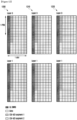
- FIGURE 12 illustrates several examples of multiplexing scheme wherein CSI-UCI is transmitted together with UL-SCH data.
- Two-layer transmission is requested with 2-PRB (one PRB includes 12 sub-carriers and one slot 7 OFDM symbols) resource allocation.
- Symbol-level vertical layer mapping is assumed for illustrative purposes.
- UL DMRS is assumed to be located in the first OFDM symbol.
- segment 2 is mapped toward the end of the slot to allow the gNB some decoding time for segment 1 before segment 2 can be decoded.
- segment 2 is mapped on the next OFDM symbol used for segment 1. Alternatively, segment 2 can be mapped right (consecutively) after segment 1.
- segment 2 is mapped in a distributed manner across the slot and PRBs.
- Other mapping schemes can be inferred from the disclosed descriptions and examples in a straightforward manner by those skilled in the art.
- segment 1 is mapped on the second OFDM symbol across a set of adjacent (contiguous) sub-carriers. Although such a localized mapping frequency domain allows a compact location of segment 1, it can lack frequency diversity.
- segment 1 is mapped in a distributed manner across the allocated set of PRBs. For example, the resulting symbols of segment 1 can be distributed more or less evenly across all the allocated set of PRBs.
- FIGURE 13 illustrates several examples of segment 1 mapped on one OFDM symbols (in this illustration, in the second OFDM symbol) in this manner. Segment 2 is not depicted in this illustration.
- Two-layer transmission is requested with 2-PRB (one PRB including 12 sub-carriers and one slot 7 OFDM symbols) resource allocation.
- Symbol-level vertical layer mapping is assumed for illustrative purposes.
- UL DMRS is assumed to be located in the first OFDM symbol and segment 1 in the second OFDM symbol.
- segment 1 occupies half of the allocated PRBs and is distributed evenly across the 2 allocated PRBs.
- segment 1 occupies two third of the allocated PRBs and is distributed evenly across the 2 allocated PRBs.
- the portion of the allocated PRBS used for segment 1 can depend on the CSI-UCI payload as well as the MCS used for UCI (e.g. to meet the required BLER).
- Other mapping schemes can be inferred from the disclosed descriptions and examples in a straightforward manner by those skilled in the art.
- segment 1 is mapped on only one OFDM symbol and, furthermore, the earliest possible OFDM symbol (in this example, the second OFDM symbol since the first OFDM symbol is used for UL DMRS).
- n>1 earliest OFDM symbols can be used. If the first OFDM symbol in the slot is used for UL DMRS, the n OFDM symbols after the first symbol are used for segment 1. Both the localized and distributed mapping across sub-carriers within the allocated PRBs can be extended accordingly when n>1 OFDM symbols are used.
- Each of the embodiments described for Component 4 applies (in general) for CSI reporting with reasonably large payload which involves at least one CSI parameter with RI-dependent payload size - either periodic, semi-persistent, or aperiodic; either wideband/partial-band (one report per a configured CSI reporting band) or subband (one report per subband within a configured CSI reporting band).
- the associated CSI-UCI can be transmitted via PUSCH by allocating a small number of PRBs or a fraction of PRB (a set of sub-carriers within one PRB and/or a set of OFDM symbols within one slot) of that allocated for UL-SCH data transmission (as indicated by resource allocation field in an UL-related DCI).
- the associated CSI-UCI can be transmitted via PUSCH by mapping it across using the same number of PRBs and/or OFDM symbols as that allocated for UL-SCH data transmission (as indicated by resource allocation field in an UL-related DCI) - the amount of time-frequency resource used for CSI-UCI transmission depends on the payload size and multiplexing scheme. As mentioned before, this can be done whether CSI-UCI is multiplexed with UL-SCH data or not.
- the offset can be larger or smaller for higher rank values.
- a minimum (lower bound) MCS for CSI-UCI can be defined to ensure that the MCS for CSI-UCI transmission does not fall below a certain value.
- the MCS for CSI-UCI can be lowered, when necessary, using repetition coding.
- CSI-UCI can be transmitted with a different number of layers (rank) from UL data.
- the number of layers used for CSI-UCI transmission is less than or equal to that used for UL data.
- both the number of layers and the MCS used for CSI-UCI transmission are determined by the number of layers and the MCS used for UL data transmission as indicated in an associated UL-related DCI, along with at least one offset value (analogous to beta offset for LTE).
- the number of layers and the MCS used for CSI-UCI transmission can be either jointly or separately determined.
- An example procedure is as follows. For a given offset value, the MCS used for CSI-UCI transmission is first determined from the MCS used for UL data transmission.
- the rank for CSI-UCI transmission can be lowered.
- the process of determining MCS is then repeated for the lower rank value. Therefore, MCS and rank for CSI-UCI transmission are jointly determined based on the MCS and rank for UL data transmission as well as the offset(s).
- CSI-UCI can be transmitted with rank > 1 only when the total payload for CSI-UCI is larger than X (where X can be fixed in specification or configured via higher-layer signaling).
- CSI-UCI is transmitted together with data
- a condition which can also be used (either in conjunction with another condition or separately) is when the data is transmitted with rank > 1. Otherwise, CSI-UCI is transmitted with rank-1.
- this payload-dependent criterion can be linked (or implicitly used) with the channel coding scheme. That is, CSI-UCI can be transmitted with rank >1 only when channel coding scheme A is used (e.g. LDPC).
- CSI-UCI symbols when CSI-UCI is transmitted with rank-1 (one layer), several alternatives are applicable.
- CSI-UCI symbols (after modulation mapping) can be repeated across all the layers used for UL data transmission.
- CSI-UCI symbols (after modulation mapping) can be transmitted across all the layers with specification-transparent transmit diversity scheme.
- CSI-UCI symbols (after modulation mapping) can be transmitted across all the layers with RE-level or PRB-level precoder cycling.
- CSI-UCI symbols (after modulation mapping) can be transmitted across all the layers with an assigned rank-1 precoder (signaled to the UE via an UL-related UCI which includes the associated UL grant and CSI request).
- CSI-UCI symbols (after modulation mapping) can be transmitted across all the layers with a rank-1 precoder determined by the UE.
- A-CSI aperiodic CSI
- SP-CSI semi-persistent CSI
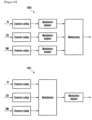
- FIGURE 14 illustrates a flowchart for an example method 1400 wherein a UE receives CSI configuration information and reports multi-segment CSI according to an embodiment of the present disclosure.
- the method 1400 can be performed by the UE 116.
- the method 1400 begins with the UE receiving and decoding CSI configuration information (step 1401).
- the UE then calculates a CSI according to the configuration information (step 1402) and transmits the CSI on an uplink (UL) channel (step 1403).
- the CSI includes N>1 segments and is transmitted in one slot, and a first segment includes at least a rank indicator (RI) and at least one other CSI parameter.
- N can be two where a first segment also includes a channel quality indicator (CQI) for a first codeword (CW).
- CQI channel quality indicator
- the first segment in addition to a CQI for a first CW, the first segment also includes two indicators that correspond to a number of reported wideband amplitude coefficients for a first and a second layer, respectively. This is prevalent for Type II CSI supported in NR.
- a second segment includes CSI parameters associated with precoding matrix indicator (PMI).
- PMI precoding matrix indicator
- the second segment also includes a CQI for a second CW when the reported RI in the first segment is greater than four.
- the first segment also includes CSI-reference-signal resource indicator (CRI).
- FIGURE 15 illustrates a flowchart for an example method 1500 wherein a BS transmits CSI configuration information and receives multi-segment CSI reporting for a UE (labeled as UE-k) according to an embodiment of the present disclosure.
- the method 1500 can be performed by the BS 102.
- the method 1500 begins with the BS generating CSI configuration information for a UE (termed UE-k) (step 1501), followed by transmitting the CSI configuration information to UE-k (step 1502). The BS then receives CSI reporting from UE-k (step 1503).
- the CSI includes N>1 segments and is transmitted in one slot, and a first segment includes at least a rank indicator (RI) and at least one other CSI parameter.
- N can be two where a first segment also includes a channel quality indicator (CQI) for a first codeword (CW).
- CQI channel quality indicator
- the first segment in addition to a CQI for a first CW, the first segment also includes two indicators that correspond to a number of reported wideband amplitude coefficients for a first and a second layer, respectively. This is prevalent for Type II CSI supported in NR.
- a second segment includes CSI parameters associated with precoding matrix indicator (PMI).
- PMI precoding matrix indicator
- the second segment also includes a CQI for a second CW when the reported RI in the first segment is greater than four.
- the first segment also includes CSI-reference-signal resource indicator (CRI).
- FIGURES 14 and 15 illustrate examples of methods for receiving configuration information and configuring a UE, respectively, various changes could be made to FIGURES 14 and 15 .
- steps in each figure could overlap, occur in parallel, occur in a different order, occur multiple times, or not be performed in one or more embodiments.
Landscapes
- Engineering & Computer Science (AREA)
- Signal Processing (AREA)
- Computer Networks & Wireless Communication (AREA)
- Quality & Reliability (AREA)
- Physics & Mathematics (AREA)
- Mathematical Physics (AREA)
- Mobile Radio Communication Systems (AREA)
- Time-Division Multiplex Systems (AREA)
Claims (8)
- Ein Verfahren, das von einem Endgerät in einem drahtlosen Kommunikationssystem durchgeführt wird, wobei das Verfahren dadurch gekennzeichnet ist, dass:Identifizierung eines ersten CSI-Teils (Channel State Information) und eines zweiten CSI-Teils, wobei:der erste CSI-Teil einen Rangindikator (RI) und eine erste Kanalqualitätsinformation (CQI) umfasst, die mit einem ersten Codewort verbunden ist,der zweite CSI-Teil einen Vorcodierungsmatrixindikator, PMI, und einen zweiten CQI umfasst, der mit einem zweiten Codewort verbunden ist, falls der RI größer als 4 ist, undder zweite CSI-Teil umfasst den PMI ohne den zweiten CQI, der dem zweiten Codewort zugeordnet ist, wenn der RI gleich oder kleiner als 4 ist;die Kodierung des ersten CSI-Teils und die Kodierung des zweiten CSI-Teils getrennt durchführen;Durchführen eines Multiplexens des kodierten ersten CSI-Teils und des kodierten zweiten CSI-Teils, und Durchführen einer Modulation des gemultiplexten ersten CSI-Teils und des zweiten CSI-Teils; undÜbertragen eines CSI-Berichts, der den ersten CSI-Teil und den zweiten CSI-Teil enthält, an eine Basisstation,wobei eine Nutzlastgröße des zweiten CSI-Teils auf der Grundlage eines Wertes der im ersten CSI-Teil enthaltenen RI identifiziert wird.
- Das Verfahren nach Anspruch 1 umfasst ferner:Empfangen von Downlink-Steuerungsinformationen (DCI) von der Basisstation, die sich auf den Uplink beziehen, und Planen einer Uplink-Übertragung,wobei der CSI-Bericht mit den Daten eines gemeinsam genutzten Aufwärtskanals, UL-SCH, gemultiplext wird und auf der Grundlage von Ressourcenzuweisungsinformationen, die in der aufwärtsstreckenbezogenen DCI enthalten sind, auf einem gemeinsam genutzten physikalischen Aufwärtskanal, PUSCH, an die Basisstation übertragen wird.
- Ein Endgerät (116) in einem drahtlosen Kommunikationssystem, wobei das Endgerät dadurch gekennzeichnet ist, dass es konfiguriert ist, um:einen ersten CSI-Teil (Channel State Information) und einen zweiten CSI-Teil identifizieren, wobei:der erste CSI-Teil einen Rangindikator (RI) und eine erste Kanalqualitätsinformation (CQI) umfasst, die mit einem ersten Codewort verbunden ist,der zweite CSI-Teil einen Vorcodierungsmatrixindikator, PMI, und einen zweiten CQI umfasst, der mit einem zweiten Codewort verbunden ist, falls der RI größer als 4 ist, undder zweite CSI-Teil umfasst den PMI ohne den zweiten CQI, der dem zweiten Codewort zugeordnet ist, wenn der RI gleich oder kleiner als 4 ist,die Codierung des ersten CSI-Teils und die Codierung des zweiten CSI-Teils getrennt durchführen,Durchführen eines Multiplexens des codierten ersten CSI-Teils und des codierten zweiten CSI-Teils, und Durchführen einer Modulation des gemultiplexten ersten CSI-Teils und des zweiten CSI-Teils, undÜbermittlung eines CSI-Berichts, der den ersten CSI-Teil und den zweiten CSI-Teil enthält, an eine Basisstation,wobei eine Nutzlastgröße des zweiten CSI-Teils auf der Grundlage eines Wertes der im ersten CSI-Teil enthaltenen RI identifiziert wird.
- Endgerät (116) nach Anspruch 3, wobei das Endgerät (116) ferner konfiguriert ist, um von der Basisstation Downlink-Steuerungsinformationen, DCI, die sich auf die Aufwärtsstrecke beziehen, zu empfangen, die eine Aufwärtsstreckenübertragung planen, und
wobei der CSI-Bericht mit Daten eines gemeinsam genutzten Aufwärtskanals, UL-SCH, gemultiplext wird und auf der Grundlage von in der aufwärtsstreckenbezogenen DCI enthaltenen Ressourcenzuweisungsinformationen auf einem gemeinsam genutzten physikalischen Aufwärtskanal, PUSCH, an die Basisstation übertragen wird. - Ein Verfahren, das von einer Basisstation in einem drahtlosen Kommunikationssystem durchgeführt wird, wobei das Verfahren dadurch gekennzeichnet ist, dass:Empfangen eines CSI-Berichts (Channel State Information) von einem Terminal, wobei der CSI-Bericht einen ersten CSI-Teil und einen separaten zweiten CSI-Teil umfasst,Dekodieren des ersten CSI-Teils, der einen Rangindikator (RI) und eine erste Kanalqualitätsinformation (CQI) umfasst, die mit einem ersten Codewort verbunden ist; undDekodierung des zweiten CSI-Teils, wobei der zweite CSI-Teil auf der Grundlage des dekodierten ersten CSI-Teils getrennt vom ersten CSI-Teil dekodiert wird,wobei der zweite CSI-Teil einen Vorcodierungsmatrixindikator, PMI, und einen zweiten CQI umfasst, der mit einem zweiten Codewort verbunden ist, falls der RI größer als 4 ist,wobei der zweite CSI-Teil den PMI ohne den zweiten CQI umfasst, der dem zweiten Codewort zugeordnet ist, falls der RI gleich oder kleiner als 4 ist, undwobei eine Nutzlastgröße des zweiten CSI-Teils von einem Wert des RI abhängt, der in dem decodierten ersten CSI-Teil enthalten ist.
- Das Verfahren nach Anspruch 5 umfasst ferner:Übertragung von Downlink-Steuerungsinformationen (DCI) für die Aufwärtsstrecke an das Endgerät, um eine Übertragung in der Aufwärtsstrecke zu planen,wobei der CSI-Bericht mit den Daten eines gemeinsam genutzten Aufwärtskanals, UL-SCH, gemultiplext wird und vom Endgerät auf einem gemeinsam genutzten physikalischen Aufwärtskanal, PUSCH, auf der Grundlage der in der aufwärtsbezogenen DCI enthaltenen Ressourcenzuweisungsinformationen empfangen wird.
- Eine Basisstation in einem drahtlosen Kommunikationssystem, wobei die Basisstation dadurch gekennzeichnet ist, dass sie konfiguriert ist, um:von einem Endgerät einen CSI-Bericht (Channel State Information) empfangen, wobei der CSI-Bericht einen ersten CSI-Teil und einen separaten zweiten CSI-Teil umfasst,Dekodieren des ersten CSI-Teils, der einen Rangindikator (RI) und eine erste Kanalqualitätsinformation (CQI) umfasst, die mit einem ersten Codewort verbunden ist, undden zweiten CSI-Teil dekodieren, wobei der zweite CSI-Teil getrennt vom ersten CSI-Teil auf der Grundlage des dekodierten ersten CSI-Teils dekodiert wird,wobei der zweite CSI-Teil einen Vorcodierungsmatrixindikator, PMI, und einen zweiten CQI umfasst, der mit einem zweiten Codewort verbunden ist, falls der RI größer als 4 ist,wobei der zweite CSI-Teil den PMI ohne den zweiten CQI umfasst, der dem zweiten Codewort zugeordnet ist, falls der RI gleich oder kleiner als 4 ist, undwobei eine Nutzlastgröße des zweiten CSI-Teils von einem Wert des RI abhängt, der in dem decodierten ersten CSI-Teil enthalten ist.
- Basisstation nach Anspruch 7, wobei die Basisstation ferner konfiguriert ist, um an das Endgerät Downlink-Steuerungsinformationen, DCI, zu übertragen, die eine Uplink-Übertragung planen, und
wobei der CSI-Bericht mit den Daten eines gemeinsam genutzten Aufwärtskanals (UL-SCH) gemultiplext wird und von dem Endgerät auf einem gemeinsam genutzten physikalischen Aufwärtskanal (PUSCH) auf der Grundlage von Ressourcenzuweisungsinformationen empfangen wird, die in der aufwärtsstreckenbezogenen DCI enthalten sind.
Priority Applications (1)
| Application Number | Priority Date | Filing Date | Title |
|---|---|---|---|
| EP24179055.9A EP4401329A3 (de) | 2016-12-16 | 2017-12-14 | Verfahren und vorrichtung zum multiplexen von kanalstatusinformationen |
Applications Claiming Priority (10)
| Application Number | Priority Date | Filing Date | Title |
|---|---|---|---|
| US201662435536P | 2016-12-16 | 2016-12-16 | |
| US201762446145P | 2017-01-13 | 2017-01-13 | |
| US201762462431P | 2017-02-23 | 2017-02-23 | |
| US201762470633P | 2017-03-13 | 2017-03-13 | |
| US201762501492P | 2017-05-04 | 2017-05-04 | |
| US201762521848P | 2017-06-19 | 2017-06-19 | |
| US201762558078P | 2017-09-13 | 2017-09-13 | |
| US201762559287P | 2017-09-15 | 2017-09-15 | |
| US15/833,746 US10873439B2 (en) | 2016-12-16 | 2017-12-06 | Method and apparatus for multiplexing channel state information |
| PCT/KR2017/014739 WO2018111007A1 (en) | 2016-12-16 | 2017-12-14 | Method and apparatus for multiplexing channel state information |
Related Child Applications (2)
| Application Number | Title | Priority Date | Filing Date |
|---|---|---|---|
| EP24179055.9A Division EP4401329A3 (de) | 2016-12-16 | 2017-12-14 | Verfahren und vorrichtung zum multiplexen von kanalstatusinformationen |
| EP24179055.9A Division-Into EP4401329A3 (de) | 2016-12-16 | 2017-12-14 | Verfahren und vorrichtung zum multiplexen von kanalstatusinformationen |
Publications (4)
| Publication Number | Publication Date |
|---|---|
| EP3529929A1 EP3529929A1 (de) | 2019-08-28 |
| EP3529929A4 EP3529929A4 (de) | 2020-05-06 |
| EP3529929B1 true EP3529929B1 (de) | 2024-07-10 |
| EP3529929C0 EP3529929C0 (de) | 2024-07-10 |
Family
ID=62559482
Family Applications (2)
| Application Number | Title | Priority Date | Filing Date |
|---|---|---|---|
| EP17880781.4A Active EP3529929B1 (de) | 2016-12-16 | 2017-12-14 | Verfahren und vorrichtung zum multiplexing von kanalstatusinformationen |
| EP24179055.9A Pending EP4401329A3 (de) | 2016-12-16 | 2017-12-14 | Verfahren und vorrichtung zum multiplexen von kanalstatusinformationen |
Family Applications After (1)
| Application Number | Title | Priority Date | Filing Date |
|---|---|---|---|
| EP24179055.9A Pending EP4401329A3 (de) | 2016-12-16 | 2017-12-14 | Verfahren und vorrichtung zum multiplexen von kanalstatusinformationen |
Country Status (9)
| Country | Link |
|---|---|
| US (2) | US10873439B2 (de) |
| EP (2) | EP3529929B1 (de) |
| JP (2) | JP7191827B2 (de) |
| KR (2) | KR102653765B1 (de) |
| CN (2) | CN115426091B (de) |
| AU (2) | AU2017374457B2 (de) |
| CA (2) | CA3296789A1 (de) |
| MY (1) | MY197585A (de) |
| WO (1) | WO2018111007A1 (de) |
Families Citing this family (60)
| Publication number | Priority date | Publication date | Assignee | Title |
|---|---|---|---|---|
| EP3411958B1 (de) * | 2016-02-04 | 2019-10-23 | Telefonaktiebolaget LM Ericsson (PUBL) | Verfahren zur anpassung einer strahlform eines strahls |
| US10110284B2 (en) * | 2016-11-03 | 2018-10-23 | At&T Intellectual Property I, L.P. | Providing a format indicator comprising rank indication and channel state information spatial domain resolution type |
| US10893512B2 (en) * | 2017-01-16 | 2021-01-12 | Mediatek Inc. | Resource element (RE) allocation for uplink control information (UCI) on physical uplink shared channel (PUSCH) |
| CN108462552B (zh) | 2017-02-17 | 2022-04-12 | 华为技术有限公司 | 一种多码字传输方法及装置 |
| AU2018233234B2 (en) * | 2017-03-14 | 2022-02-17 | Guangdong Oppo Mobile Telecommunications Corp., Ltd. | Aggregation methods, gNodeBs, user equipments and storage medium |
| EP3602933B1 (de) | 2017-03-24 | 2023-11-01 | Telefonaktiebolaget LM Ericsson (publ) | Semipersistente csi-rückkopplung über pusch |
| US10742290B2 (en) * | 2017-04-13 | 2020-08-11 | Samsung Electronics Co., Ltd. | High-resolution CSI reporting based on unequal bit allocation in advanced wireless communication systems |
| WO2018199703A1 (ko) * | 2017-04-28 | 2018-11-01 | 엘지전자 주식회사 | 무선 통신 시스템에서 채널 상태 정보를 보고하기 위한 방법 및 이를 위한 장치 |
| CN108809386B (zh) | 2017-05-05 | 2023-06-16 | 华为技术有限公司 | 传输预编码矩阵的指示方法和设备 |
| CN108111199A (zh) * | 2017-05-05 | 2018-06-01 | 中兴通讯股份有限公司 | 信道状态信息的反馈、接收方法及装置、设备、存储介质 |
| WO2018227614A1 (en) * | 2017-06-16 | 2018-12-20 | Qualcomm Incorporated | Channel state information feedback for flexible uplink control signaling |
| US10567113B2 (en) * | 2017-08-11 | 2020-02-18 | Samsung Electronics Co., Ltd. | Method and apparatus for channel quality indicator (CQI) and channel state information (CSI) reporting |
| EP3480970B1 (de) * | 2017-09-08 | 2021-05-05 | LG Electronics Inc. | Verfahren zur meldung von kanalstatusinformationen in einem drahtloskommunikationssystem und vorrichtung dafür |
| CN111095848B (zh) * | 2017-09-11 | 2022-11-15 | 苹果公司 | 新无线电中物理上行链路共享信道上的信道状态信息报告 |
| US10951290B2 (en) * | 2017-10-26 | 2021-03-16 | Apple Inc. | Channel state information report for phase tracking reference signal port selection |
| US11516834B2 (en) * | 2017-11-13 | 2022-11-29 | Qualcomm Incorporated | Uplink control information transmission |
| US10700758B2 (en) * | 2017-11-16 | 2020-06-30 | Mediatek Inc. | Control information for CSI acquisition and beam management |
| CN109922531B (zh) * | 2017-12-13 | 2021-03-09 | 电信科学技术研究院 | 一种传输方法、终端及基站 |
| US10305568B1 (en) * | 2017-12-15 | 2019-05-28 | Motorola Mobility Llc | Coding main beam information in CSI codebook |
| US11283506B2 (en) * | 2018-01-07 | 2022-03-22 | Lg Electronics Inc. | Method for transmitting and receiving phase tracking reference signal between terminal and base station in wireless communication system, and device for supporting same |
| US11296767B2 (en) * | 2018-05-04 | 2022-04-05 | Lg Electronics Inc. | Method for reporting channel state information in wireless communication system, and device therefor |
| CN110635883B (zh) * | 2018-06-25 | 2022-09-27 | 中兴通讯股份有限公司 | 信息反馈方法及装置,存储介质,电子装置 |
| EP3844901A4 (de) * | 2018-08-30 | 2022-09-07 | Nokia Technologies Oy | Frequenzzeitbereichskanalhärtung und overhead-verringerung |
| BR112021005871A2 (pt) * | 2018-09-28 | 2021-07-27 | Huawei Technologies Co., Ltd. | método de indicação de matriz de pré-codificação, aparelho de comunicações, e meio de armazenamento |
| WO2020091542A1 (ko) * | 2018-11-02 | 2020-05-07 | 엘지전자 주식회사 | 무선 통신 시스템에서 채널 상태 정보를 보고하기 위한 방법 및 이를 위한 장치 |
| WO2020118501A1 (en) * | 2018-12-11 | 2020-06-18 | Qualcomm Incorporated | Basis report for compressed csi feedback with non-contiguous subband configuration |
| KR102629072B1 (ko) * | 2018-11-13 | 2024-01-24 | 한국전자통신연구원 | 무선 통신 시스템에서의 데이터 재전송 방법 및 장치 |
| CN111327352B (zh) * | 2018-12-17 | 2021-07-16 | 华为技术有限公司 | 一种通信方法及设备 |
| CN113261226B (zh) * | 2019-01-10 | 2024-08-13 | 索尼集团公司 | 通信装置、基础设施设备及方法 |
| WO2020142974A1 (en) | 2019-01-10 | 2020-07-16 | Qualcomm Incorporated | Feedback for type ii channel state information |
| US12021589B2 (en) * | 2019-01-11 | 2024-06-25 | Lg Electronics Inc. | Method for reporting channel state information in wireless communication system, and apparatus therefor |
| CN111277360B (zh) * | 2019-01-11 | 2023-02-21 | 维沃移动通信有限公司 | 信道状态信息csi报告的传输方法、终端及网络设备 |
| WO2020147104A1 (en) * | 2019-01-18 | 2020-07-23 | Qualcomm Incorporated | Layer-specific coefficient quantity and/or quantization scheme reporting for type ii channel state information compression |
| WO2020160687A1 (en) * | 2019-02-06 | 2020-08-13 | Qualcomm Incorporated | Reporting rank indication and layer-specific coefficient quantities for type ii channel state information (csi) compression using two-part csi |
| CN113439396B (zh) * | 2019-02-15 | 2024-04-26 | 上海诺基亚贝尔股份有限公司 | 装置、方法和计算机程序 |
| EP3939368B1 (de) * | 2019-03-15 | 2023-08-16 | Fg Innovation Company Limited | Verfahren und vorrichtung zum multiplexing von uci |
| CN114026937A (zh) * | 2019-05-09 | 2022-02-08 | 株式会社Ntt都科摩 | 用户终端以及无线通信方法 |
| BR112021026640A2 (pt) * | 2019-07-15 | 2022-03-22 | Qualcomm Inc | Sinal de referência de informação de estado de canal para operação de banda larga |
| CN110535509B (zh) * | 2019-08-16 | 2024-09-27 | 中兴通讯股份有限公司 | 一种信息反馈和接收方法、装置和存储介质 |
| US11432277B2 (en) | 2019-08-26 | 2022-08-30 | Qualcomm Incorporated | Techniques for determining resources for transmitting wireless communications |
| DE102019125959A1 (de) * | 2019-09-26 | 2021-04-01 | Bayerische Motoren Werke Aktiengesellschaft | Verfahren und System zum Bereitstellen einer Kommunikationsfunktion in einem Fortbewegungsmittel |
| EP3799490B1 (de) * | 2019-09-27 | 2022-11-16 | ASUSTek Computer Inc. | Verfahren und vorrichtung zur übertragung von vorrichtung-zu-vorrichtung-kanalmessungen in einem drahtlosen kommunikationssystem |
| WO2021056580A1 (zh) * | 2019-09-29 | 2021-04-01 | 华为技术有限公司 | 信号接收、发送方法及装置 |
| US11356163B2 (en) * | 2019-10-04 | 2022-06-07 | Qualcomm Incorporated | Multiplexing of CSI with SL-SCH for sidelink communications |
| US12206478B2 (en) * | 2020-01-10 | 2025-01-21 | Lenovo (Singapore) Pte. Ltd., New Tech Park | Transmitting sidelink CSI using an uplink channel |
| WO2021159324A1 (en) * | 2020-02-12 | 2021-08-19 | Apple Inc. | Channel state information reporting |
| US11387880B2 (en) * | 2020-02-28 | 2022-07-12 | Qualcomm Incorporated | Channel state information feedback using channel compression and reconstruction |
| US11750258B2 (en) * | 2020-03-12 | 2023-09-05 | Samsung Electronics Co., Ltd. | Method and apparatus for CSI reporting |
| US12184344B2 (en) | 2020-08-24 | 2024-12-31 | Telefonaktiebolaget Lm Ericsson (Publ) | UE aided antenna calibration |
| KR20230061420A (ko) * | 2020-09-02 | 2023-05-08 | 광동 오포 모바일 텔레커뮤니케이션즈 코포레이션 리미티드 | Csi 보고 및 수신 방법, 장치, 단말 기기, 네트워크 기기 |
| WO2022082701A1 (en) * | 2020-10-23 | 2022-04-28 | Lenovo (Beijing) Limited | Csi feedback for multi-trp dl transmission |
| EP4238226A1 (de) * | 2020-10-30 | 2023-09-06 | Lenovo (Singapore) Pte. Ltd. | Konfiguration von kanalstatusinformationsberichten |
| CN112839307B (zh) * | 2021-01-11 | 2021-12-17 | 台州信元建筑节能科技有限公司 | 一种基于设备间通信的智能楼宇管理方法及系统 |
| CN117121391B (zh) | 2021-03-31 | 2024-04-16 | 高通股份有限公司 | 非相干联合传输信道状态信息中的秩指示符和层指示符信令 |
| JP7830432B2 (ja) * | 2021-04-13 | 2026-03-16 | 株式会社Nttドコモ | 端末、無線通信システム及び無線通信方法 |
| CN115706634A (zh) * | 2021-08-05 | 2023-02-17 | 华为技术有限公司 | 一种信道信息反馈的方法及通信装置 |
| EP4391408A4 (de) * | 2021-08-20 | 2025-08-27 | Lg Electronics Inc | Verfahren und vorrichtung zum senden und empfangen von kanalstatusinformationen in einem drahtloskommunikationssystem |
| WO2023060608A1 (en) * | 2021-10-16 | 2023-04-20 | Qualcomm Incorporated | Uplink control information (uci) for non-precoding matrix indicator (pmi) -based channel state information (csi) |
| US12003660B2 (en) | 2021-12-31 | 2024-06-04 | Avila Technology, LLC | Method and system to implement secure real time communications (SRTC) between WebRTC and the internet of things (IoT) |
| JP7818625B2 (ja) | 2022-03-14 | 2026-02-20 | 中興通訊股▲ふん▼有限公司 | チャネル状態情報報告 |
Family Cites Families (57)
| Publication number | Priority date | Publication date | Assignee | Title |
|---|---|---|---|---|
| US8199725B2 (en) * | 2008-03-28 | 2012-06-12 | Research In Motion Limited | Rank indicator transmission during discontinuous reception |
| US8406171B2 (en) * | 2008-08-01 | 2013-03-26 | Texas Instruments Incorporated | Network MIMO reporting, control signaling and transmission |
| WO2011041623A1 (en) * | 2009-10-01 | 2011-04-07 | Interdigital Patent Holdings, Inc. | Uplink control data transmission |
| KR101789618B1 (ko) * | 2009-11-09 | 2017-10-25 | 엘지전자 주식회사 | 다중 안테나 전송 기법을 지원하기 위한 효율적인 제어정보 전송 방법 및 장치 |
| EP2522095A2 (de) * | 2010-01-08 | 2012-11-14 | InterDigital Patent Holdings, Inc. | Übertragung von kanalzustandsinformationen für mehrere träger |
| CN105450360B (zh) * | 2010-01-08 | 2018-12-11 | 交互数字专利控股公司 | 使用载波聚合报告信道状态信息的方法及wtru |
| US9270427B2 (en) * | 2010-01-11 | 2016-02-23 | Futurewei Technologies, Inc. | System and method for multiplexing control and data channels in a multiple input, multiple output communications system |
| WO2011122911A2 (ko) * | 2010-04-01 | 2011-10-06 | 엘지전자 주식회사 | 무선 접속 시스템에서 채널상태정보 전송 방법 |
| US9083501B2 (en) * | 2010-04-05 | 2015-07-14 | Qualcomm Incorporated | Feedback of control information for multiple carriers |
| WO2011162520A2 (ko) | 2010-06-22 | 2011-12-29 | 엘지전자 주식회사 | 채널 상태 정보 전송 방법 및 장치 |
| KR20120029338A (ko) * | 2010-09-16 | 2012-03-26 | 엘지전자 주식회사 | 다중 안테나 지원 무선 통신 시스템에서 효율적인 피드백 방법 및 장치 |
| US20120069833A1 (en) * | 2010-09-16 | 2012-03-22 | Molnar Karl J | Channel state information reporting for a successively decoded, precoded multi-antenna transmission |
| US8885496B2 (en) * | 2010-10-08 | 2014-11-11 | Sharp Kabushiki Kaisha | Uplink control information transmission on backward compatible PUCCH formats with carrier aggregation |
| US20120127869A1 (en) * | 2010-11-22 | 2012-05-24 | Sharp Laboratories Of America, Inc. | Multiple channel state information (csi) reporting on the physical uplink shared channel (pusch) with carrier aggregation |
| US20120182944A1 (en) * | 2011-01-19 | 2012-07-19 | Telefonaktiebolaget Lm Ericsson (Publ) | Methods and arrangements for signaling channel state information |
| US20130294282A1 (en) * | 2011-01-23 | 2013-11-07 | Lg Electronics Inc. | Method and apparatus for transmitting an uplink signal by a relay in a wireless communcation system |
| KR20140052948A (ko) * | 2011-02-23 | 2014-05-07 | 엘지전자 주식회사 | 무선접속시스렘에서 상향링크제어정보 코딩방법 및 전송방법 |
| US8971197B2 (en) * | 2011-04-01 | 2015-03-03 | Industrial Technology Research Institute | Method for reporting uplink control information and wireless communication device using the same |
| JP5896619B2 (ja) * | 2011-04-05 | 2016-03-30 | シャープ株式会社 | 端末装置、基地局装置、通信システムおよび通信方法 |
| US20130195008A1 (en) * | 2011-08-12 | 2013-08-01 | Interdigital Patent Holdings, Inc. | Providing Feedback For Multiple Downlink Multiple-Input-Multiple-Output (MIMO) Streams |
| WO2013032271A2 (ko) * | 2011-09-02 | 2013-03-07 | 엘지전자 주식회사 | 무선 통신 시스템에서 채널상태정보를 전송하는 방법 및 장치 |
| US20130088978A1 (en) * | 2011-10-07 | 2013-04-11 | Nokia Siemens Networks Oy | Joint Encoding of Rank and CQI Feedback For Comp |
| KR20130039644A (ko) * | 2011-10-12 | 2013-04-22 | 삼성전자주식회사 | 통신 시스템에서의 피드백 송수신 방법 및 장치 |
| WO2013070577A1 (en) * | 2011-11-07 | 2013-05-16 | Motorola Mobility Llc | Method and apparatus for csi feedback for joint processing schemes in an orthogonal frequency division multiplexing communication system with coordinated multi-point transmission |
| US9220087B1 (en) * | 2011-12-08 | 2015-12-22 | Marvell International Ltd. | Dynamic point selection with combined PUCCH/PUSCH feedback |
| CN103178891B (zh) * | 2011-12-23 | 2015-08-19 | 华为技术有限公司 | 用户设备反馈信息的传输和处理方法及装置 |
| CN104081827B (zh) | 2012-01-27 | 2018-04-13 | 三星电子株式会社 | 用于非周期性的信道状态信息的多个过程的报告 |
| EP2810508B1 (de) * | 2012-01-30 | 2015-08-12 | Telefonaktiebolaget LM Ericsson (Publ) | Zeitmultiplexierte kanalstatusinformationsmeldung in einem drahtlosen mehrantennen-kommunikationssystem |
| US10158472B2 (en) * | 2012-02-28 | 2018-12-18 | Lg Electronics Inc. | Method for transmitting channel state information report and user equipment, and method for receiving channel state information report and base station |
| US11546787B2 (en) | 2012-05-09 | 2023-01-03 | Samsung Electronics Co., Ltd. | CSI definitions and feedback modes for coordinated multi-point transmission |
| US9692573B2 (en) * | 2012-05-17 | 2017-06-27 | Lg Electronics Inc. | Method and device for reporting channel state information |
| ES2650841T3 (es) * | 2012-05-18 | 2018-01-22 | Telefónica S.A. | Un método y un sistema para la notificación de CSI en redes de LTE de acuerdo con la movilidad del equipo de usuario |
| JP6324954B2 (ja) * | 2012-06-18 | 2018-05-16 | サムスン エレクトロニクス カンパニー リミテッド | 協調マルチポイント送信のための非周期的及び周期的csiフィードバックモード |
| WO2014000206A1 (zh) * | 2012-06-28 | 2014-01-03 | 华为技术有限公司 | 信道状态信息处理方法及终端 |
| CN104604283B (zh) * | 2012-08-30 | 2019-04-26 | Lg 电子株式会社 | 在无线通信系统中估计信道的方法和设备 |
| EP2919506B1 (de) * | 2012-11-12 | 2018-08-15 | Huawei Technologies Co., Ltd. | Berichterstattung von kanalstatusinformationen, benutzervorrichtung und basisstation dafür |
| CN104956717B (zh) * | 2012-12-27 | 2019-07-19 | Lg电子株式会社 | 在无线接入系统中发送和接收信道质量指示符信息的方法和支持该方法的装置 |
| US20160006553A1 (en) * | 2013-02-24 | 2016-01-07 | Lg Electronics Inc. | Method and apparatus for reporting downlink channel state |
| US9143212B2 (en) | 2013-02-25 | 2015-09-22 | Texas Instruments Incorporated | Codebook sub-sampling for CSI feedback on PUCCH for 4Tx MIMO |
| US9698887B2 (en) * | 2013-03-08 | 2017-07-04 | Qualcomm Incorporated | Systems and methods for enhanced MIMO operation |
| WO2014142504A1 (ko) * | 2013-03-11 | 2014-09-18 | 엘지전자 주식회사 | 무선 통신 시스템에서 채널 상태 정보 보고 방법 및 장치 |
| US9768849B2 (en) | 2013-04-04 | 2017-09-19 | Lg Electronics Inc. | Method and apparatus for reporting channel status information in wireless communication system |
| WO2014178615A1 (ko) * | 2013-04-29 | 2014-11-06 | 엘지전자 주식회사 | 무선 통신 시스템에서 채널상태정보 전송 방법 및 장치 |
| RU2639949C2 (ru) * | 2013-06-05 | 2017-12-25 | Эл Джи Электроникс Инк. | Способ и устройство для передачи информации о состоянии канала в системе беспроводной связи |
| CN105340192B (zh) * | 2013-06-20 | 2020-03-06 | 瑞典爱立信有限公司 | 映射码字的方法、无线电基站和计算机可读存储介质 |
| JP6374981B2 (ja) * | 2014-05-19 | 2018-08-15 | パナソニック インテレクチュアル プロパティ コーポレーション オブ アメリカPanasonic Intellectual Property Corporation of America | ネットワーク支援型の干渉の除去および抑制のためのチャネル状態情報報告の機能強化 |
| WO2016010354A1 (ko) * | 2014-07-16 | 2016-01-21 | 엘지전자(주) | 무선 통신 시스템에서 채널 상태 정보 송수신 방법 및 이를 위한 장치 |
| EP3471307B1 (de) * | 2015-01-19 | 2026-02-18 | QUALCOMM Incorporated | Reduktion von csi-feedback-overhead für fd-mimo |
| CN107567695B (zh) | 2015-03-27 | 2021-02-02 | 三星电子株式会社 | 大规模天线系统中的资源分配设备和方法 |
| US9967012B2 (en) * | 2015-05-06 | 2018-05-08 | Samsung Electronics Co., Ltd. | Method and apparatus for channel state information (CSI) reporting |
| US10057027B2 (en) * | 2015-05-07 | 2018-08-21 | Electronics And Telecommunications Research Institute | Method and apparatus for receiving reference signal |
| US10211964B2 (en) * | 2015-07-29 | 2019-02-19 | Samsung Electronics Co., Ltd. | Method and apparatus for CSI reporting |
| US10523285B2 (en) * | 2015-11-05 | 2019-12-31 | Intel Corporation | Full dimension multiple input multiple output communication systems and methods |
| WO2017090987A1 (ko) * | 2015-11-23 | 2017-06-01 | 엘지전자(주) | 무선 통신 시스템에서 채널 상태 정보 송수신 방법 및 이를 위한 장치 |
| KR20180013811A (ko) * | 2016-07-29 | 2018-02-07 | 아서스테크 컴퓨터 인코포레이션 | 무선 통신 시스템에서 빔 동작을 위한 채널 상태 정보 리포트를 위한 방법 및 장치 |
| US10939389B2 (en) * | 2016-08-12 | 2021-03-02 | Telefonaktiebolaget Lm Ericsson (Publ) | Configurable codebook for advanced CSI feedback overhead reduction |
| EP3480970B1 (de) * | 2017-09-08 | 2021-05-05 | LG Electronics Inc. | Verfahren zur meldung von kanalstatusinformationen in einem drahtloskommunikationssystem und vorrichtung dafür |
-
2017
- 2017-12-06 US US15/833,746 patent/US10873439B2/en active Active
- 2017-12-14 EP EP17880781.4A patent/EP3529929B1/de active Active
- 2017-12-14 CN CN202210913147.4A patent/CN115426091B/zh active Active
- 2017-12-14 EP EP24179055.9A patent/EP4401329A3/de active Pending
- 2017-12-14 CN CN201780076819.8A patent/CN110073620B/zh active Active
- 2017-12-14 WO PCT/KR2017/014739 patent/WO2018111007A1/en not_active Ceased
- 2017-12-14 MY MYPI2019003378A patent/MY197585A/en unknown
- 2017-12-14 CA CA3296789A patent/CA3296789A1/en active Pending
- 2017-12-14 AU AU2017374457A patent/AU2017374457B2/en active Active
- 2017-12-14 KR KR1020227041393A patent/KR102653765B1/ko active Active
- 2017-12-14 CA CA3047229A patent/CA3047229A1/en active Pending
- 2017-12-14 KR KR1020197012963A patent/KR102472227B1/ko active Active
- 2017-12-14 JP JP2019531950A patent/JP7191827B2/ja active Active
-
2020
- 2020-12-21 US US17/129,578 patent/US12413368B2/en active Active
-
2022
- 2022-06-24 AU AU2022204501A patent/AU2022204501B2/en active Active
- 2022-12-07 JP JP2022195732A patent/JP7504970B2/ja active Active
Also Published As
| Publication number | Publication date |
|---|---|
| EP4401329A3 (de) | 2024-10-16 |
| US20210111853A1 (en) | 2021-04-15 |
| AU2022204501B2 (en) | 2023-09-14 |
| JP7191827B2 (ja) | 2022-12-19 |
| KR20190088045A (ko) | 2019-07-25 |
| JP2023036643A (ja) | 2023-03-14 |
| CN115426091B (zh) | 2025-05-30 |
| KR102472227B1 (ko) | 2022-11-29 |
| CN110073620B (zh) | 2022-08-12 |
| AU2022204501A1 (en) | 2022-07-14 |
| AU2017374457A2 (en) | 2020-01-30 |
| KR20220162879A (ko) | 2022-12-08 |
| CA3047229A1 (en) | 2018-06-21 |
| EP3529929A4 (de) | 2020-05-06 |
| EP3529929C0 (de) | 2024-07-10 |
| CA3296789A1 (en) | 2026-03-02 |
| MY197585A (en) | 2023-06-26 |
| JP7504970B2 (ja) | 2024-06-24 |
| WO2018111007A1 (en) | 2018-06-21 |
| US10873439B2 (en) | 2020-12-22 |
| AU2017374457B2 (en) | 2022-03-24 |
| AU2017374457A1 (en) | 2019-05-30 |
| EP3529929A1 (de) | 2019-08-28 |
| CN110073620A (zh) | 2019-07-30 |
| JP2020502922A (ja) | 2020-01-23 |
| EP4401329A2 (de) | 2024-07-17 |
| US20180175993A1 (en) | 2018-06-21 |
| US12413368B2 (en) | 2025-09-09 |
| CN115426091A (zh) | 2022-12-02 |
| KR102653765B1 (ko) | 2024-04-03 |
Similar Documents
| Publication | Publication Date | Title |
|---|---|---|
| AU2022204501B2 (en) | Method and apparatus for multiplexing channel state information | |
| US12149977B2 (en) | Method and apparatus for multiplexing higher-resolution channel state information (CSI) | |
| EP3973640B1 (de) | Verfahren und vorrichtung zur auslösung eines mehrstrahlberichts | |
| US11128362B2 (en) | Method and apparatus for multiplexing and omitting channel state information | |
| US11128354B2 (en) | Method and apparatus to enable segmented CSI reporting in wireless communication systems | |
| US10985823B2 (en) | Method and apparatus for codebook subset restriction | |
| US12052078B2 (en) | Method and apparatus for CSI parameter configuration in wireless communication systems | |
| EP3607692B1 (de) | Verfahren und vorrichtung für ein kanalzustandsinformationsreferenzsignal (csi-rs) | |
| EP4274114A2 (de) | Verfahren und vorrichtung zur ressourcenbasierten csi-erfassung in erweiterten drahtlosen kommunikationssystemen | |
| CN110999120B (zh) | 用于信道质量指示符和信道状态信息报告的方法和装置 | |
| US20190068267A1 (en) | Method and apparatus for codebook subset restriction for csi reporting in advanced wireless communication systems | |
| EP3769432A1 (de) | Uplink-leistungsregelung für fortschrittliche drahtlose kommunikationssysteme | |
| EP4133612B1 (de) | Verfahren und vorrichtung zur kapazitätssignalisierung zur ermöglichung einer uplink-übertragung mit voller leistung |
Legal Events
| Date | Code | Title | Description |
|---|---|---|---|
| STAA | Information on the status of an ep patent application or granted ep patent |
Free format text: STATUS: THE INTERNATIONAL PUBLICATION HAS BEEN MADE |
|
| PUAI | Public reference made under article 153(3) epc to a published international application that has entered the european phase |
Free format text: ORIGINAL CODE: 0009012 |
|
| STAA | Information on the status of an ep patent application or granted ep patent |
Free format text: STATUS: REQUEST FOR EXAMINATION WAS MADE |
|
| 17P | Request for examination filed |
Effective date: 20190522 |
|
| AK | Designated contracting states |
Kind code of ref document: A1 Designated state(s): AL AT BE BG CH CY CZ DE DK EE ES FI FR GB GR HR HU IE IS IT LI LT LU LV MC MK MT NL NO PL PT RO RS SE SI SK SM TR |
|
| AX | Request for extension of the european patent |
Extension state: BA ME |
|
| DAV | Request for validation of the european patent (deleted) | ||
| DAX | Request for extension of the european patent (deleted) | ||
| A4 | Supplementary search report drawn up and despatched |
Effective date: 20200408 |
|
| RIC1 | Information provided on ipc code assigned before grant |
Ipc: H04B 7/0456 20170101ALI20200402BHEP Ipc: H04L 1/00 20060101AFI20200402BHEP Ipc: H04B 7/06 20060101ALI20200402BHEP Ipc: H04L 5/00 20060101ALI20200402BHEP |
|
| STAA | Information on the status of an ep patent application or granted ep patent |
Free format text: STATUS: EXAMINATION IS IN PROGRESS |
|
| 17Q | First examination report despatched |
Effective date: 20210114 |
|
| GRAP | Despatch of communication of intention to grant a patent |
Free format text: ORIGINAL CODE: EPIDOSNIGR1 |
|
| STAA | Information on the status of an ep patent application or granted ep patent |
Free format text: STATUS: GRANT OF PATENT IS INTENDED |
|
| INTG | Intention to grant announced |
Effective date: 20231011 |
|
| GRAJ | Information related to disapproval of communication of intention to grant by the applicant or resumption of examination proceedings by the epo deleted |
Free format text: ORIGINAL CODE: EPIDOSDIGR1 |
|
| STAA | Information on the status of an ep patent application or granted ep patent |
Free format text: STATUS: EXAMINATION IS IN PROGRESS |
|
| GRAP | Despatch of communication of intention to grant a patent |
Free format text: ORIGINAL CODE: EPIDOSNIGR1 |
|
| STAA | Information on the status of an ep patent application or granted ep patent |
Free format text: STATUS: GRANT OF PATENT IS INTENDED |
|
| INTC | Intention to grant announced (deleted) | ||
| INTG | Intention to grant announced |
Effective date: 20240130 |
|
| GRAS | Grant fee paid |
Free format text: ORIGINAL CODE: EPIDOSNIGR3 |
|
| GRAA | (expected) grant |
Free format text: ORIGINAL CODE: 0009210 |
|
| STAA | Information on the status of an ep patent application or granted ep patent |
Free format text: STATUS: THE PATENT HAS BEEN GRANTED |
|
| AK | Designated contracting states |
Kind code of ref document: B1 Designated state(s): AL AT BE BG CH CY CZ DE DK EE ES FI FR GB GR HR HU IE IS IT LI LT LU LV MC MK MT NL NO PL PT RO RS SE SI SK SM TR |
|
| REG | Reference to a national code |
Ref country code: CH Ref legal event code: EP |
|
| REG | Reference to a national code |
Ref country code: DE Ref legal event code: R096 Ref document number: 602017083268 Country of ref document: DE |
|
| U01 | Request for unitary effect filed |
Effective date: 20240711 |
|
| U07 | Unitary effect registered |
Designated state(s): AT BE BG DE DK EE FI FR IT LT LU LV MT NL PT SE SI Effective date: 20240730 |
|
| PG25 | Lapsed in a contracting state [announced via postgrant information from national office to epo] |
Ref country code: NO Free format text: LAPSE BECAUSE OF FAILURE TO SUBMIT A TRANSLATION OF THE DESCRIPTION OR TO PAY THE FEE WITHIN THE PRESCRIBED TIME-LIMIT Effective date: 20241010 |
|
| PG25 | Lapsed in a contracting state [announced via postgrant information from national office to epo] |
Ref country code: GR Free format text: LAPSE BECAUSE OF FAILURE TO SUBMIT A TRANSLATION OF THE DESCRIPTION OR TO PAY THE FEE WITHIN THE PRESCRIBED TIME-LIMIT Effective date: 20241011 Ref country code: PL Free format text: LAPSE BECAUSE OF FAILURE TO SUBMIT A TRANSLATION OF THE DESCRIPTION OR TO PAY THE FEE WITHIN THE PRESCRIBED TIME-LIMIT Effective date: 20240710 |
|
| PG25 | Lapsed in a contracting state [announced via postgrant information from national office to epo] |
Ref country code: IS Free format text: LAPSE BECAUSE OF FAILURE TO SUBMIT A TRANSLATION OF THE DESCRIPTION OR TO PAY THE FEE WITHIN THE PRESCRIBED TIME-LIMIT Effective date: 20241110 |
|
| PG25 | Lapsed in a contracting state [announced via postgrant information from national office to epo] |
Ref country code: HR Free format text: LAPSE BECAUSE OF FAILURE TO SUBMIT A TRANSLATION OF THE DESCRIPTION OR TO PAY THE FEE WITHIN THE PRESCRIBED TIME-LIMIT Effective date: 20240710 |
|
| PG25 | Lapsed in a contracting state [announced via postgrant information from national office to epo] |
Ref country code: ES Free format text: LAPSE BECAUSE OF FAILURE TO SUBMIT A TRANSLATION OF THE DESCRIPTION OR TO PAY THE FEE WITHIN THE PRESCRIBED TIME-LIMIT Effective date: 20240710 Ref country code: RS Free format text: LAPSE BECAUSE OF FAILURE TO SUBMIT A TRANSLATION OF THE DESCRIPTION OR TO PAY THE FEE WITHIN THE PRESCRIBED TIME-LIMIT Effective date: 20241010 |
|
| U20 | Renewal fee for the european patent with unitary effect paid |
Year of fee payment: 8 Effective date: 20241226 |
|
| PG25 | Lapsed in a contracting state [announced via postgrant information from national office to epo] |
Ref country code: RS Free format text: LAPSE BECAUSE OF FAILURE TO SUBMIT A TRANSLATION OF THE DESCRIPTION OR TO PAY THE FEE WITHIN THE PRESCRIBED TIME-LIMIT Effective date: 20241010 Ref country code: PL Free format text: LAPSE BECAUSE OF FAILURE TO SUBMIT A TRANSLATION OF THE DESCRIPTION OR TO PAY THE FEE WITHIN THE PRESCRIBED TIME-LIMIT Effective date: 20240710 Ref country code: NO Free format text: LAPSE BECAUSE OF FAILURE TO SUBMIT A TRANSLATION OF THE DESCRIPTION OR TO PAY THE FEE WITHIN THE PRESCRIBED TIME-LIMIT Effective date: 20241010 Ref country code: IS Free format text: LAPSE BECAUSE OF FAILURE TO SUBMIT A TRANSLATION OF THE DESCRIPTION OR TO PAY THE FEE WITHIN THE PRESCRIBED TIME-LIMIT Effective date: 20241110 Ref country code: HR Free format text: LAPSE BECAUSE OF FAILURE TO SUBMIT A TRANSLATION OF THE DESCRIPTION OR TO PAY THE FEE WITHIN THE PRESCRIBED TIME-LIMIT Effective date: 20240710 Ref country code: GR Free format text: LAPSE BECAUSE OF FAILURE TO SUBMIT A TRANSLATION OF THE DESCRIPTION OR TO PAY THE FEE WITHIN THE PRESCRIBED TIME-LIMIT Effective date: 20241011 Ref country code: ES Free format text: LAPSE BECAUSE OF FAILURE TO SUBMIT A TRANSLATION OF THE DESCRIPTION OR TO PAY THE FEE WITHIN THE PRESCRIBED TIME-LIMIT Effective date: 20240710 |
|
| PG25 | Lapsed in a contracting state [announced via postgrant information from national office to epo] |
Ref country code: SM Free format text: LAPSE BECAUSE OF FAILURE TO SUBMIT A TRANSLATION OF THE DESCRIPTION OR TO PAY THE FEE WITHIN THE PRESCRIBED TIME-LIMIT Effective date: 20240710 |
|
| PG25 | Lapsed in a contracting state [announced via postgrant information from national office to epo] |
Ref country code: CZ Free format text: LAPSE BECAUSE OF FAILURE TO SUBMIT A TRANSLATION OF THE DESCRIPTION OR TO PAY THE FEE WITHIN THE PRESCRIBED TIME-LIMIT Effective date: 20240710 |
|
| PG25 | Lapsed in a contracting state [announced via postgrant information from national office to epo] |
Ref country code: SK Free format text: LAPSE BECAUSE OF FAILURE TO SUBMIT A TRANSLATION OF THE DESCRIPTION OR TO PAY THE FEE WITHIN THE PRESCRIBED TIME-LIMIT Effective date: 20240710 |
|
| PLBE | No opposition filed within time limit |
Free format text: ORIGINAL CODE: 0009261 |
|
| STAA | Information on the status of an ep patent application or granted ep patent |
Free format text: STATUS: NO OPPOSITION FILED WITHIN TIME LIMIT |
|
| 26N | No opposition filed |
Effective date: 20250411 |
|
| PG25 | Lapsed in a contracting state [announced via postgrant information from national office to epo] |
Ref country code: MC Free format text: LAPSE BECAUSE OF FAILURE TO SUBMIT A TRANSLATION OF THE DESCRIPTION OR TO PAY THE FEE WITHIN THE PRESCRIBED TIME-LIMIT Effective date: 20240710 |
|
| REG | Reference to a national code |
Ref country code: CH Ref legal event code: PL |
|
| PG25 | Lapsed in a contracting state [announced via postgrant information from national office to epo] |
Ref country code: CH Free format text: LAPSE BECAUSE OF NON-PAYMENT OF DUE FEES Effective date: 20241231 |
|
| PG25 | Lapsed in a contracting state [announced via postgrant information from national office to epo] |
Ref country code: IE Free format text: LAPSE BECAUSE OF NON-PAYMENT OF DUE FEES Effective date: 20241214 |
|
| PG25 | Lapsed in a contracting state [announced via postgrant information from national office to epo] |
Ref country code: RO Free format text: LAPSE BECAUSE OF FAILURE TO SUBMIT A TRANSLATION OF THE DESCRIPTION OR TO PAY THE FEE WITHIN THE PRESCRIBED TIME-LIMIT Effective date: 20240710 |
|
| PGFP | Annual fee paid to national office [announced via postgrant information from national office to epo] |
Ref country code: GB Payment date: 20251120 Year of fee payment: 9 |
|
| U20 | Renewal fee for the european patent with unitary effect paid |
Year of fee payment: 9 Effective date: 20251223 |