EP3530146A1 - Profilés pour la construction de structures porteuses et système d'assemblage correspondant - Google Patents
Profilés pour la construction de structures porteuses et système d'assemblage correspondant Download PDFInfo
- Publication number
- EP3530146A1 EP3530146A1 EP19000093.5A EP19000093A EP3530146A1 EP 3530146 A1 EP3530146 A1 EP 3530146A1 EP 19000093 A EP19000093 A EP 19000093A EP 3530146 A1 EP3530146 A1 EP 3530146A1
- Authority
- EP
- European Patent Office
- Prior art keywords
- legs
- post
- elements
- profiles
- section
- Prior art date
- Legal status (The legal status is an assumption and is not a legal conclusion. Google has not performed a legal analysis and makes no representation as to the accuracy of the status listed.)
- Granted
Links
Images


Classifications
-
- F—MECHANICAL ENGINEERING; LIGHTING; HEATING; WEAPONS; BLASTING
- F16—ENGINEERING ELEMENTS AND UNITS; GENERAL MEASURES FOR PRODUCING AND MAINTAINING EFFECTIVE FUNCTIONING OF MACHINES OR INSTALLATIONS; THERMAL INSULATION IN GENERAL
- F16B—DEVICES FOR FASTENING OR SECURING CONSTRUCTIONAL ELEMENTS OR MACHINE PARTS TOGETHER, e.g. NAILS, BOLTS, CIRCLIPS, CLAMPS, CLIPS OR WEDGES; JOINTS OR JOINTING
- F16B12/00—Jointing of furniture or the like, e.g. hidden from exterior
- F16B12/10—Jointing of furniture or the like, e.g. hidden from exterior using pegs, bolts, tenons, clamps, clips, or the like
- F16B12/28—Jointing of furniture or the like, e.g. hidden from exterior using pegs, bolts, tenons, clamps, clips, or the like for metal furniture parts
- F16B12/38—Jointing of furniture or the like, e.g. hidden from exterior using pegs, bolts, tenons, clamps, clips, or the like for metal furniture parts using snap-action elements
-
- A—HUMAN NECESSITIES
- A47—FURNITURE; DOMESTIC ARTICLES OR APPLIANCES; COFFEE MILLS; SPICE MILLS; SUCTION CLEANERS IN GENERAL
- A47B—TABLES; DESKS; OFFICE FURNITURE; CABINETS; DRAWERS; GENERAL DETAILS OF FURNITURE
- A47B57/00—Cabinets, racks or shelf units, characterised by features for adjusting shelves or partitions
- A47B57/30—Cabinets, racks or shelf units, characterised by features for adjusting shelves or partitions with means for adjusting the height of detachable shelf supports
- A47B57/48—Cabinets, racks or shelf units, characterised by features for adjusting shelves or partitions with means for adjusting the height of detachable shelf supports consisting of tongues, pins or similar projecting means coacting with openings
-
- A—HUMAN NECESSITIES
- A47—FURNITURE; DOMESTIC ARTICLES OR APPLIANCES; COFFEE MILLS; SPICE MILLS; SUCTION CLEANERS IN GENERAL
- A47B—TABLES; DESKS; OFFICE FURNITURE; CABINETS; DRAWERS; GENERAL DETAILS OF FURNITURE
- A47B96/00—Details of cabinets, racks or shelf units not covered by a single one of groups A47B43/00 - A47B95/00; General details of furniture
- A47B96/14—Bars, uprights, struts, or like supports, for cabinets, brackets, or the like
- A47B96/1466—Bars, uprights, struts, or like supports, for cabinets, brackets, or the like with longitudinal grooves
- A47B96/1475—Bars, uprights, struts, or like supports, for cabinets, brackets, or the like with longitudinal grooves and perforations
-
- A—HUMAN NECESSITIES
- A47—FURNITURE; DOMESTIC ARTICLES OR APPLIANCES; COFFEE MILLS; SPICE MILLS; SUCTION CLEANERS IN GENERAL
- A47B—TABLES; DESKS; OFFICE FURNITURE; CABINETS; DRAWERS; GENERAL DETAILS OF FURNITURE
- A47B47/00—Cabinets, racks or shelf units, characterised by features related to dismountability or building-up from elements
- A47B47/02—Cabinets, racks or shelf units, characterised by features related to dismountability or building-up from elements made of metal only
Definitions
- the invention relates to profiles and structural elements for the construction of supporting structures, such as e.g. Shelving, support racks, bookshelves, and the coupling and connection system between the individual structural elements for a quick and easy assembly / disassembly, without the use of specific tools to achieve.
- supporting structures such as e.g. Shelving, support racks, bookshelves, and the coupling and connection system between the individual structural elements for a quick and easy assembly / disassembly, without the use of specific tools to achieve.
- a "frame” known which consists of vertical posts and horizontal side rails, or shelves; wherein the posts consist of parallel profiles which between them, in the region of the vertical connecting surfaces, a number of equally spaced suspension elements for the respective depending of the longitudinal beams, or the horizontal, insertable between the composite profiles of the posts shelves have.
- the posts of said structure are complex in their manufacture, are heavy and their cleaning is tedious.
- GB 2048351 A1 is a structure for furniture, such as shelves, boxes or tables known which consist of metallic profiles with eg rectangular cross-section and which are connected at their ends.
- the posts of these structures consist of profiles which have a substantially U-shaped cross-section, wherein the flange projecting parallel from the connecting flange are double and spaced from each other.
- the longitudinal legs of said parallel flanges are bent against the connecting flange and are provided with spaced apart and to the longitudinal extent of the post profile horizontally extending slots.
- the structural elements which can be attached to these posts have final formations which can be inserted between the oblong and inflected flanges of the posts, with projecting lateral projections engaging the slots provided on the posts. This intervention is activated by inserting a wedge element.
- the horizontal structural elements on the post by means, mounted on the Endausformept lever which have a Nockenausformung acting on a cross rung, which is slidably mounted on the Endausformung and upon actuation of the lever in the slots of the post intervenes.
- connection system requires final formations with a complex locking mechanism which is expensive to manufacture and requires the use of movable elements such as wedges or cam-shaped lever mechanisms for the purpose of locking / releasing the individual structural elements on the posts.
- movable elements such as wedges or cam-shaped lever mechanisms for the purpose of locking / releasing the individual structural elements on the posts.
- the object of the invention is to provide metallic support structures for the storage, storage and / or the exhibition of goods which consist essentially of vertical posts, fasteners or self-supporting, attachable to these elements and horizontal side rails and / or shelves of the aforementioned type, which are simple and inexpensive to produce, convenient to install / dismantle and easy to clean, preferably metallic simple and inexpensive to produce profiles and use secure coupling and connection systems which provide the structure with considerable stability.
- the support structures which can be realized with the use of profiles and elements according to the invention comprise substantially vertical posts with tubular cross-section, horizontal connecting elements or cantilevers with preferably inverted T-shaped cross section, horizontal side members with U-shaped cross section or tubular, rectangular cross section and shelves with circumferential bent edges.
- the tubular profile of the posts is inventively characterized in that the two outermost legs of the wall which forms the profile inwardly, are bent in the cross section to extend in a straight line while touching each other or are spaced a little from each other.
- said inwardly projecting legs form a right angle with the corresponding outer wall of the profile, said deflection region extending inwardly along, or near, the vertical centerline of the corresponding wall of the profile. It is not excluded the use of compound posts, so that at several than one side, has legs projecting inwards in the cross-section.
- On both of the said inner legs elongated holes or openings are provided according to the invention substantially on the entire longitudinal extent which are arranged on both legs in a corresponding position and spaced from each other.
- the profile of the connecting elements or of the self-attaching elements preferably has a T-shaped cross-section, which can be made of a simple type, for example by extrusion, or can consist of two elements of substantially identical cross-section which are produced by profiling of sheet metal and are arranged longitudinally to one another. or transverse direction are slidably connected so that by mutual displacement is a, variable in length, element available.
- these T-elements have at both ends or, in the case of cantilevered attachment only at one of the ends, a hooked end which is provided on each of the sides with at least one hooking projection which is suitable for insertion into the two inner legs of the aforementioned tubular, the vertical post forming profile, provided slots or openings penetrate and mount.
- the coupling between the aforesaid connecting element or the cantilever element, which preferably has a T-shaped cross-section with the tubular profile which forms the post, is effected by inserting the vertical hooking end of the T-shaped element, which in this area has no horizontal flanges, between the both vertical inner legs of the tubular profile of the post, these legs being slightly spread apart, the penetration of the hooking projections, which protrude laterally from the left and right sides of said hooking end, into the corresponding oblong holes or openings provided on both inner legs of the post, is reached.
- the definitive hooking is done by pushing down the said hooked end inserted between the two legs, or the corresponding connecting element or the cantilevered element, which is pressed down because of the hooking projections provided angled surfaces, a train of the legs of the post against the intermediate Einattide done, whereby a secure, stable and durable hooking is achieved.
- the surfaces or the shape of the Einhticianvorsprünge, or the slots in which they engage and hang be designed such that, in addition to the mutual contraction of the inner legs of the tubular profile of the post, a force component is formed which is suitable to pull the T-section element with the face of the lateral horizontal flanges against the outer surface of the tubular profile of the post, thereby securing the abutment against the post, the position at 90 ° to the post, and the stability of the connection.
- a vertical to be provided externally projecting rib At the said two vertical ribs of the profile of the post can act a corresponding notch which are frontally provided on the horizontal flanges of the T-shaped profile which is pulled horizontally against the latter by the effect of hanging on the post.
- the shelves which are horizontally fastened to the fasteners or to the cantilevered elements which are horizontally fitted and hung on the vertical tubular uprights may be made of sheet metal and have flanges and / or hook-in notches on the underside;
- the invention does not exclude the use of known shelves made of different materials which with known devices for hanging and / or attaching to the corresponding fasteners or to the cantilevered elements with T-shaped cross-section, from.
- the horizontal side members according to the invention may be profiles with U-shaped, tubular or rectangular in cross-section which by extrusion or are made by profiling of sheet metal; at the ends, these are provided with suspension brackets and / or lower Einh brieflykerben which are arranged at a distance from the ends in order to be attached to the corresponding connecting elements or cantilevered elements, which for example have a T-shaped cross-section.
- the invention does not exclude the use of side members made of different materials, which can be fastened or suspended on the connecting elements or on the self-supporting elements with a T-shaped cross section or on the vertical posts by means of known devices.
- the invention does not exclude the production of the tubular profile of the posts and also that of the connecting elements or the self-supporting elements of plastic, e.g. by extrusion, out.
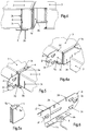
- the structure of a shelf is according to the invention of vertical posts 1, to which a plurality of horizontal connecting elements or cantilevered elements 2 with inverted T-shaped cross-section, mutually vertically spaced, can be used and fastened, composed. At the said fasteners or cantilevered elements 2 horizontal side members 4 and / or horizontal shelves 3 can be attached.
- the invention proposes that the tubular post 1 two rectilinear, inward in has the cross-section projecting and abutting one another, or to each other by a distance from each other leg 1 a, which dimension substantially corresponds to the strength of the Ein Strukturdes 2i of the horizontal Veitatiselements or the cantilevered element 2.
- Said legs 1a have elongated holes or openings 1c into which projections 2c are inserted and which project on both sides from the hooking end 2i of the horizontal connecting element or cantilevered element 2 with a T-shaped cross section.
- the elongated holes or openings 1c may have a downwardly narrowing shape.
- the hooking projections 2c provided at the hooked end 2i are at least two, one at the right and one at the left side, advantageously more than two for stable hooking and preferably their position with respect to the end face of the hooking end 2i be arranged that this surface is applied to the inner surface of the post 1.
- the elongated holes 1c on the legs 1a of the post 1 and / or the EinhNicolvorsprünge 2c are formed such that, during the Einhnature on the connecting element 2, a force component acts, which tends to pull the Ein devisde 2i inward of the cross section of the post 1 and to pull the two legs 1a against the said intermediate hanging end 2i.
- a vertical outwardly projecting longitudinal rib 1b can be provided corresponding to the region of the angling of the two legs 1a of the post inwardly of the cross section, where these form an angle of approximately 90 ° with the outer wall of the profile.
- a notch 2 g which is provided on the front side on the horizontal flanges 2 b of the connecting element or cantilevered element 2, can cooperate.
- This notch 2g and / or the cross section of the ribs 1b can be formed according to the invention such that by the movement of the element 2 against the post 1, which by the force component during the hooking movement between the element 2 and the post 1 is effected, an approximation between the two ribs 1b and a contraction against the vertical flange of the Ein Strukturdes 2i takes place.
- the connecting element or cantilevered element 2 of T-shaped cross section may be of simpler, e.g. by extrusion produced type or composite type, consisting of two substantially identical elements with T-shaped cross-section, be longitudinally displaceable composite type.
- both elements 2 are made by profiling of sheet metal, the vertical flange is single-layered, one of the horizontal flanges is double-layered bent over, while the second horizontal flange 2a is single-layered.
- the two-layer horizontal flange 2a is formed on one of the elements 2, which form the connecting element or the cantilever element, that a distance corresponding to the sheet thickness is maintained between the legs, the assembly of both elements with T-shaped cross-section by inserting the single-layer flange of one element in the free corresponding space of the other element up to the stop of the two vertical flanges, possible.
- This embodiment makes it possible to provide respective longitudinal elongated holes 2e on both assembled and penetrated by the Löngslöcher 2e bolt 2f with heads at both ends secured elements 2 to thereby achieve a longitudinal displacement between the two assembled elements 2, for the purpose of changing the longitudinal extent.
- the invention does not exclude that the two joined elements 2 are connected by a single bolt passing through in order to form a longitudinally extendable connecting element, so that a pivoting movement between the two joined elements is possible in order, in certain situations, to assemble / Disassembly to facilitate the post.
- shelves 3 made of sheet metal with bent edges can be attached, which have at the ends Einh brieflyflansche 3a, 3b and / or latching notches 3c.
- These Einh brieflyflansche allow direct hooking on the vertical flange 2a of the connecting elements or cantilevered elements 2, or the mutual hooking between two ends of two shelves 3.
- the latching notches 3c allow direct engagement with the vertical flanges 2a of the elements 2, which are provided with corresponding notches 2d can be provided. It is also possible to use elements with double-sided hooking possibility 5, which are attached to the elements 2 with hooking flanges 5a arranged on both sides, for the purpose of accommodating the hooking flanges 3a of the shelves 3.
- longitudinal members 4 may be attached to the connecting elements or cantilevered elements 2 with e.g. U-shaped or rectangular tubular cross section are attached. These side rails may be provided at their ends with hooking and / or latching notches similar to those on the shelves.
- the side members 4 may alternatively be provided with Einhticianzitch which are identical to the Einhticiangendes 2i of the connecting elements or cantilevered elements 2, but rotated by 90 ° to the longitudinal extent of the longitudinal members 4 are arranged to be used on the post 1 between the flanges 1a.
- known sensors 6 can be mounted between the connecting elements 2 and the shelves attached to be able to indicate changes in weight on the shelves can.
Landscapes
- Engineering & Computer Science (AREA)
- General Engineering & Computer Science (AREA)
- Mechanical Engineering (AREA)
- Assembled Shelves (AREA)
- Joining Of Building Structures In Genera (AREA)
- Rod-Shaped Construction Members (AREA)
Applications Claiming Priority (1)
| Application Number | Priority Date | Filing Date | Title |
|---|---|---|---|
| IT102018000002975A IT201800002975A1 (it) | 2018-02-23 | 2018-02-23 | Profilati per la composizione di strutture portanti e sistema di accoppiamento e giunzione fra essi |
Publications (2)
| Publication Number | Publication Date |
|---|---|
| EP3530146A1 true EP3530146A1 (fr) | 2019-08-28 |
| EP3530146B1 EP3530146B1 (fr) | 2021-06-02 |
Family
ID=62167798
Family Applications (1)
| Application Number | Title | Priority Date | Filing Date |
|---|---|---|---|
| EP19000093.5A Active EP3530146B1 (fr) | 2018-02-23 | 2019-02-20 | Profilés et éléments de structure pour la construction de structures porteuses |
Country Status (2)
| Country | Link |
|---|---|
| EP (1) | EP3530146B1 (fr) |
| IT (1) | IT201800002975A1 (fr) |
Cited By (2)
| Publication number | Priority date | Publication date | Assignee | Title |
|---|---|---|---|---|
| SE1951398A1 (en) * | 2019-12-05 | 2021-06-06 | Ikea Supply Ag | A support bracket, an elongated support member and a goods storage system |
| RU232980U1 (ru) * | 2024-12-27 | 2025-03-31 | Публичное акционерное общество "Северсталь" (ПАО "Северсталь") | Соединитель стоек по высоте |
Citations (2)
| Publication number | Priority date | Publication date | Assignee | Title |
|---|---|---|---|---|
| GB2048351A (en) * | 1979-03-26 | 1980-12-10 | Haines K W | Furniture frameworks |
| EP0151902A2 (fr) * | 1984-02-13 | 1985-08-21 | Brennwald, Erwin | Profilé métallique perforé |
Family Cites Families (1)
| Publication number | Priority date | Publication date | Assignee | Title |
|---|---|---|---|---|
| DE3401125A1 (de) * | 1984-01-14 | 1985-07-18 | Walter Dr.-Ing. 5100 Aachen Jürgens | Profil |
-
2018
- 2018-02-23 IT IT102018000002975A patent/IT201800002975A1/it unknown
-
2019
- 2019-02-20 EP EP19000093.5A patent/EP3530146B1/fr active Active
Patent Citations (2)
| Publication number | Priority date | Publication date | Assignee | Title |
|---|---|---|---|---|
| GB2048351A (en) * | 1979-03-26 | 1980-12-10 | Haines K W | Furniture frameworks |
| EP0151902A2 (fr) * | 1984-02-13 | 1985-08-21 | Brennwald, Erwin | Profilé métallique perforé |
Cited By (5)
| Publication number | Priority date | Publication date | Assignee | Title |
|---|---|---|---|---|
| SE1951398A1 (en) * | 2019-12-05 | 2021-06-06 | Ikea Supply Ag | A support bracket, an elongated support member and a goods storage system |
| WO2021112752A1 (fr) * | 2019-12-05 | 2021-06-10 | Ikea Supply Ag | Élément de support allongé et système de stockage de marchandises |
| SE544867C2 (en) * | 2019-12-05 | 2022-12-13 | Ikea Supply Ag | An elongated support member and a goods storage system |
| US12102230B2 (en) | 2019-12-05 | 2024-10-01 | Ikea Supply Ag | Elongated support member and a goods storage system |
| RU232980U1 (ru) * | 2024-12-27 | 2025-03-31 | Публичное акционерное общество "Северсталь" (ПАО "Северсталь") | Соединитель стоек по высоте |
Also Published As
| Publication number | Publication date |
|---|---|
| IT201800002975A1 (it) | 2019-08-23 |
| EP3530146B1 (fr) | 2021-06-02 |
Similar Documents
| Publication | Publication Date | Title |
|---|---|---|
| DE2502992A1 (de) | Bodenplatte | |
| DE69806697T2 (de) | Lagergestell mit Profilelementen und Befestigungsmitteln der Elemente | |
| EP3530146B1 (fr) | Profilés et éléments de structure pour la construction de structures porteuses | |
| EP3262988B1 (fr) | Système de rayons | |
| EP3137704B1 (fr) | Système de fixation pour façades de bâtiment et son utilisation | |
| EP2440721A1 (fr) | Revêtement mural | |
| DE3688113T2 (de) | Elementensatz fuer die einrichtung von ausstellungsraeumen, geschaeften und anderen orten. | |
| EP2324732A1 (fr) | Rayonnage de stockage, notamment stockage automatique de petites pièces | |
| DE10044969A1 (de) | Wandprofilleiste | |
| EP3685705B1 (fr) | Dispositif de fonctionnement avec deux profilés et une paroi | |
| DE29924191U1 (de) | Regal | |
| DE2609100C2 (de) | Bausatz für die Herstellung von Regalen variabler Größe | |
| DE29508050U1 (de) | Verkleidungssystem | |
| EP1408793B1 (fr) | Systeme d'etagere | |
| DE202007001060U1 (de) | Modulares Wandregal | |
| DE4023685C1 (en) | Support rail element for goods - has openings in rail sections to allow fitting of hooked brackets | |
| DE2225955C3 (fr) | ||
| EP0052774B1 (fr) | Armoire ou rayonnage | |
| EP1169946A1 (fr) | Profilé et système d'accouplement pour l'assemblage de structures portant une charge | |
| AT409066B (de) | Möbel mit einem tragenden gestell | |
| WO2018028844A1 (fr) | Élément profilé et système de meuble comprenant un tel élément profilé | |
| DE102009009236A1 (de) | Regalsystem | |
| DE19940168C2 (de) | Aus Blech hergestelltes Plattenelement | |
| DE19835112A1 (de) | Regal | |
| DE1779089C (de) | Zerlegbares Regal, welches Stützen und Querträger sowie an den Rändern abgekantete Regalböden aufweist und bei dem jede Stütze aus einem im Querschnitt T-förmigen Hohlprofil gebildet ist |
Legal Events
| Date | Code | Title | Description |
|---|---|---|---|
| PUAI | Public reference made under article 153(3) epc to a published international application that has entered the european phase |
Free format text: ORIGINAL CODE: 0009012 |
|
| STAA | Information on the status of an ep patent application or granted ep patent |
Free format text: STATUS: THE APPLICATION HAS BEEN PUBLISHED |
|
| AK | Designated contracting states |
Kind code of ref document: A1 Designated state(s): AL AT BE BG CH CY CZ DE DK EE ES FI FR GB GR HR HU IE IS IT LI LT LU LV MC MK MT NL NO PL PT RO RS SE SI SK SM TR |
|
| AX | Request for extension of the european patent |
Extension state: BA ME |
|
| STAA | Information on the status of an ep patent application or granted ep patent |
Free format text: STATUS: REQUEST FOR EXAMINATION WAS MADE |
|
| 17P | Request for examination filed |
Effective date: 20200214 |
|
| STAA | Information on the status of an ep patent application or granted ep patent |
Free format text: STATUS: EXAMINATION IS IN PROGRESS |
|
| 17Q | First examination report despatched |
Effective date: 20200407 |
|
| RIC1 | Information provided on ipc code assigned before grant |
Ipc: A47B 96/14 20060101ALI20200806BHEP Ipc: A47B 47/02 20060101ALN20200806BHEP Ipc: F16B 12/38 20060101ALI20200806BHEP Ipc: A47B 57/48 20060101AFI20200806BHEP |
|
| RIC1 | Information provided on ipc code assigned before grant |
Ipc: A47B 47/02 20060101ALN20200902BHEP Ipc: F16B 12/38 20060101ALI20200902BHEP Ipc: A47B 96/14 20060101ALI20200902BHEP Ipc: A47B 57/48 20060101AFI20200902BHEP |
|
| RIC1 | Information provided on ipc code assigned before grant |
Ipc: A47B 57/48 20060101AFI20201110BHEP Ipc: A47B 96/14 20060101ALI20201110BHEP Ipc: A47B 47/02 20060101ALN20201110BHEP Ipc: F16B 12/38 20060101ALI20201110BHEP |
|
| RIC1 | Information provided on ipc code assigned before grant |
Ipc: A47B 47/02 20060101ALN20201202BHEP Ipc: F16B 12/38 20060101ALI20201202BHEP Ipc: A47B 96/14 20060101ALI20201202BHEP Ipc: A47B 57/48 20060101AFI20201202BHEP |
|
| RIC1 | Information provided on ipc code assigned before grant |
Ipc: A47B 47/02 20060101ALN20201208BHEP Ipc: A47B 57/48 20060101AFI20201208BHEP Ipc: A47B 96/14 20060101ALI20201208BHEP Ipc: F16B 12/38 20060101ALI20201208BHEP |
|
| GRAP | Despatch of communication of intention to grant a patent |
Free format text: ORIGINAL CODE: EPIDOSNIGR1 |
|
| STAA | Information on the status of an ep patent application or granted ep patent |
Free format text: STATUS: GRANT OF PATENT IS INTENDED |
|
| INTG | Intention to grant announced |
Effective date: 20210115 |
|
| RIC1 | Information provided on ipc code assigned before grant |
Ipc: A47B 47/02 20060101ALN20201218BHEP Ipc: F16B 12/38 20060101ALI20201218BHEP Ipc: A47B 57/48 20060101AFI20201218BHEP Ipc: A47B 96/14 20060101ALI20201218BHEP |
|
| GRAS | Grant fee paid |
Free format text: ORIGINAL CODE: EPIDOSNIGR3 |
|
| GRAA | (expected) grant |
Free format text: ORIGINAL CODE: 0009210 |
|
| STAA | Information on the status of an ep patent application or granted ep patent |
Free format text: STATUS: THE PATENT HAS BEEN GRANTED |
|
| REG | Reference to a national code |
Ref country code: CH Ref legal event code: EP |
|
| AK | Designated contracting states |
Kind code of ref document: B1 Designated state(s): AL AT BE BG CH CY CZ DE DK EE ES FI FR GB GR HR HU IE IS IT LI LT LU LV MC MK MT NL NO PL PT RO RS SE SI SK SM TR |
|
| REG | Reference to a national code |
Ref country code: GB Ref legal event code: FG4D Free format text: NOT ENGLISH |
|
| REG | Reference to a national code |
Ref country code: AT Ref legal event code: REF Ref document number: 1397635 Country of ref document: AT Kind code of ref document: T Effective date: 20210615 |
|
| REG | Reference to a national code |
Ref country code: IE Ref legal event code: FG4D Free format text: LANGUAGE OF EP DOCUMENT: GERMAN |
|
| REG | Reference to a national code |
Ref country code: DE Ref legal event code: R096 Ref document number: 502019001511 Country of ref document: DE |
|
| REG | Reference to a national code |
Ref country code: LT Ref legal event code: MG9D |
|
| PG25 | Lapsed in a contracting state [announced via postgrant information from national office to epo] |
Ref country code: BG Free format text: LAPSE BECAUSE OF FAILURE TO SUBMIT A TRANSLATION OF THE DESCRIPTION OR TO PAY THE FEE WITHIN THE PRESCRIBED TIME-LIMIT Effective date: 20210902 Ref country code: FI Free format text: LAPSE BECAUSE OF FAILURE TO SUBMIT A TRANSLATION OF THE DESCRIPTION OR TO PAY THE FEE WITHIN THE PRESCRIBED TIME-LIMIT Effective date: 20210602 Ref country code: LT Free format text: LAPSE BECAUSE OF FAILURE TO SUBMIT A TRANSLATION OF THE DESCRIPTION OR TO PAY THE FEE WITHIN THE PRESCRIBED TIME-LIMIT Effective date: 20210602 Ref country code: HR Free format text: LAPSE BECAUSE OF FAILURE TO SUBMIT A TRANSLATION OF THE DESCRIPTION OR TO PAY THE FEE WITHIN THE PRESCRIBED TIME-LIMIT Effective date: 20210602 |
|
| REG | Reference to a national code |
Ref country code: NL Ref legal event code: MP Effective date: 20210602 |
|
| PG25 | Lapsed in a contracting state [announced via postgrant information from national office to epo] |
Ref country code: GR Free format text: LAPSE BECAUSE OF FAILURE TO SUBMIT A TRANSLATION OF THE DESCRIPTION OR TO PAY THE FEE WITHIN THE PRESCRIBED TIME-LIMIT Effective date: 20210903 Ref country code: SE Free format text: LAPSE BECAUSE OF FAILURE TO SUBMIT A TRANSLATION OF THE DESCRIPTION OR TO PAY THE FEE WITHIN THE PRESCRIBED TIME-LIMIT Effective date: 20210602 Ref country code: RS Free format text: LAPSE BECAUSE OF FAILURE TO SUBMIT A TRANSLATION OF THE DESCRIPTION OR TO PAY THE FEE WITHIN THE PRESCRIBED TIME-LIMIT Effective date: 20210602 Ref country code: NO Free format text: LAPSE BECAUSE OF FAILURE TO SUBMIT A TRANSLATION OF THE DESCRIPTION OR TO PAY THE FEE WITHIN THE PRESCRIBED TIME-LIMIT Effective date: 20210902 Ref country code: LV Free format text: LAPSE BECAUSE OF FAILURE TO SUBMIT A TRANSLATION OF THE DESCRIPTION OR TO PAY THE FEE WITHIN THE PRESCRIBED TIME-LIMIT Effective date: 20210602 Ref country code: PL Free format text: LAPSE BECAUSE OF FAILURE TO SUBMIT A TRANSLATION OF THE DESCRIPTION OR TO PAY THE FEE WITHIN THE PRESCRIBED TIME-LIMIT Effective date: 20210602 |
|
| PG25 | Lapsed in a contracting state [announced via postgrant information from national office to epo] |
Ref country code: PT Free format text: LAPSE BECAUSE OF FAILURE TO SUBMIT A TRANSLATION OF THE DESCRIPTION OR TO PAY THE FEE WITHIN THE PRESCRIBED TIME-LIMIT Effective date: 20211004 Ref country code: NL Free format text: LAPSE BECAUSE OF FAILURE TO SUBMIT A TRANSLATION OF THE DESCRIPTION OR TO PAY THE FEE WITHIN THE PRESCRIBED TIME-LIMIT Effective date: 20210602 Ref country code: RO Free format text: LAPSE BECAUSE OF FAILURE TO SUBMIT A TRANSLATION OF THE DESCRIPTION OR TO PAY THE FEE WITHIN THE PRESCRIBED TIME-LIMIT Effective date: 20210602 Ref country code: SM Free format text: LAPSE BECAUSE OF FAILURE TO SUBMIT A TRANSLATION OF THE DESCRIPTION OR TO PAY THE FEE WITHIN THE PRESCRIBED TIME-LIMIT Effective date: 20210602 Ref country code: CZ Free format text: LAPSE BECAUSE OF FAILURE TO SUBMIT A TRANSLATION OF THE DESCRIPTION OR TO PAY THE FEE WITHIN THE PRESCRIBED TIME-LIMIT Effective date: 20210602 Ref country code: SK Free format text: LAPSE BECAUSE OF FAILURE TO SUBMIT A TRANSLATION OF THE DESCRIPTION OR TO PAY THE FEE WITHIN THE PRESCRIBED TIME-LIMIT Effective date: 20210602 Ref country code: EE Free format text: LAPSE BECAUSE OF FAILURE TO SUBMIT A TRANSLATION OF THE DESCRIPTION OR TO PAY THE FEE WITHIN THE PRESCRIBED TIME-LIMIT Effective date: 20210602 Ref country code: ES Free format text: LAPSE BECAUSE OF FAILURE TO SUBMIT A TRANSLATION OF THE DESCRIPTION OR TO PAY THE FEE WITHIN THE PRESCRIBED TIME-LIMIT Effective date: 20210602 |
|
| REG | Reference to a national code |
Ref country code: DE Ref legal event code: R097 Ref document number: 502019001511 Country of ref document: DE |
|
| PLBE | No opposition filed within time limit |
Free format text: ORIGINAL CODE: 0009261 |
|
| STAA | Information on the status of an ep patent application or granted ep patent |
Free format text: STATUS: NO OPPOSITION FILED WITHIN TIME LIMIT |
|
| PG25 | Lapsed in a contracting state [announced via postgrant information from national office to epo] |
Ref country code: DK Free format text: LAPSE BECAUSE OF FAILURE TO SUBMIT A TRANSLATION OF THE DESCRIPTION OR TO PAY THE FEE WITHIN THE PRESCRIBED TIME-LIMIT Effective date: 20210602 |
|
| 26N | No opposition filed |
Effective date: 20220303 |
|
| PG25 | Lapsed in a contracting state [announced via postgrant information from national office to epo] |
Ref country code: AL Free format text: LAPSE BECAUSE OF FAILURE TO SUBMIT A TRANSLATION OF THE DESCRIPTION OR TO PAY THE FEE WITHIN THE PRESCRIBED TIME-LIMIT Effective date: 20210602 |
|
| REG | Reference to a national code |
Ref country code: DE Ref legal event code: R119 Ref document number: 502019001511 Country of ref document: DE |
|
| PG25 | Lapsed in a contracting state [announced via postgrant information from national office to epo] |
Ref country code: MC Free format text: LAPSE BECAUSE OF FAILURE TO SUBMIT A TRANSLATION OF THE DESCRIPTION OR TO PAY THE FEE WITHIN THE PRESCRIBED TIME-LIMIT Effective date: 20210602 |
|
| REG | Reference to a national code |
Ref country code: BE Ref legal event code: MM Effective date: 20220228 |
|
| PG25 | Lapsed in a contracting state [announced via postgrant information from national office to epo] |
Ref country code: LU Free format text: LAPSE BECAUSE OF NON-PAYMENT OF DUE FEES Effective date: 20220220 |
|
| PG25 | Lapsed in a contracting state [announced via postgrant information from national office to epo] |
Ref country code: FR Free format text: LAPSE BECAUSE OF NON-PAYMENT OF DUE FEES Effective date: 20220228 |
|
| PG25 | Lapsed in a contracting state [announced via postgrant information from national office to epo] |
Ref country code: IE Free format text: LAPSE BECAUSE OF NON-PAYMENT OF DUE FEES Effective date: 20220220 Ref country code: DE Free format text: LAPSE BECAUSE OF NON-PAYMENT OF DUE FEES Effective date: 20220901 |
|
| PG25 | Lapsed in a contracting state [announced via postgrant information from national office to epo] |
Ref country code: BE Free format text: LAPSE BECAUSE OF NON-PAYMENT OF DUE FEES Effective date: 20220228 |
|
| GBPC | Gb: european patent ceased through non-payment of renewal fee |
Effective date: 20230220 |
|
| PG25 | Lapsed in a contracting state [announced via postgrant information from national office to epo] |
Ref country code: GB Free format text: LAPSE BECAUSE OF NON-PAYMENT OF DUE FEES Effective date: 20230220 |
|
| PG25 | Lapsed in a contracting state [announced via postgrant information from national office to epo] |
Ref country code: GB Free format text: LAPSE BECAUSE OF NON-PAYMENT OF DUE FEES Effective date: 20230220 |
|
| PG25 | Lapsed in a contracting state [announced via postgrant information from national office to epo] |
Ref country code: MK Free format text: LAPSE BECAUSE OF FAILURE TO SUBMIT A TRANSLATION OF THE DESCRIPTION OR TO PAY THE FEE WITHIN THE PRESCRIBED TIME-LIMIT Effective date: 20210602 Ref country code: CY Free format text: LAPSE BECAUSE OF FAILURE TO SUBMIT A TRANSLATION OF THE DESCRIPTION OR TO PAY THE FEE WITHIN THE PRESCRIBED TIME-LIMIT Effective date: 20210602 |
|
| PG25 | Lapsed in a contracting state [announced via postgrant information from national office to epo] |
Ref country code: HU Free format text: LAPSE BECAUSE OF FAILURE TO SUBMIT A TRANSLATION OF THE DESCRIPTION OR TO PAY THE FEE WITHIN THE PRESCRIBED TIME-LIMIT; INVALID AB INITIO Effective date: 20190220 |
|
| PG25 | Lapsed in a contracting state [announced via postgrant information from national office to epo] |
Ref country code: TR Free format text: LAPSE BECAUSE OF FAILURE TO SUBMIT A TRANSLATION OF THE DESCRIPTION OR TO PAY THE FEE WITHIN THE PRESCRIBED TIME-LIMIT Effective date: 20210602 |
|
| PG25 | Lapsed in a contracting state [announced via postgrant information from national office to epo] |
Ref country code: MT Free format text: LAPSE BECAUSE OF FAILURE TO SUBMIT A TRANSLATION OF THE DESCRIPTION OR TO PAY THE FEE WITHIN THE PRESCRIBED TIME-LIMIT Effective date: 20210602 |
|
| REG | Reference to a national code |
Ref country code: CH Ref legal event code: U11 Free format text: ST27 STATUS EVENT CODE: U-0-0-U10-U11 (AS PROVIDED BY THE NATIONAL OFFICE) Effective date: 20260301 |
|
| PGFP | Annual fee paid to national office [announced via postgrant information from national office to epo] |
Ref country code: AT Payment date: 20260225 Year of fee payment: 8 |
|
| PGFP | Annual fee paid to national office [announced via postgrant information from national office to epo] |
Ref country code: IT Payment date: 20260226 Year of fee payment: 8 |
|
| PGFP | Annual fee paid to national office [announced via postgrant information from national office to epo] |
Ref country code: CH Payment date: 20260301 Year of fee payment: 8 |