EP3530171A1 - Halteplatte mit dichtungselement - Google Patents
Halteplatte mit dichtungselement Download PDFInfo
- Publication number
- EP3530171A1 EP3530171A1 EP18158393.1A EP18158393A EP3530171A1 EP 3530171 A1 EP3530171 A1 EP 3530171A1 EP 18158393 A EP18158393 A EP 18158393A EP 3530171 A1 EP3530171 A1 EP 3530171A1
- Authority
- EP
- European Patent Office
- Prior art keywords
- passage opening
- sealing element
- base plate
- plate according
- holding plate
- Prior art date
- Legal status (The legal status is an assumption and is not a legal conclusion. Google has not performed a legal analysis and makes no representation as to the accuracy of the status listed.)
- Granted
Links
Images
Classifications
-
- A—HUMAN NECESSITIES
- A47—FURNITURE; DOMESTIC ARTICLES OR APPLIANCES; COFFEE MILLS; SPICE MILLS; SUCTION CLEANERS IN GENERAL
- A47L—DOMESTIC WASHING OR CLEANING; SUCTION CLEANERS IN GENERAL
- A47L9/00—Details or accessories of suction cleaners, e.g. mechanical means for controlling the suction or for effecting pulsating action; Storing devices specially adapted to suction cleaners or parts thereof; Carrying-vehicles specially adapted for suction cleaners
- A47L9/10—Filters; Dust separators; Dust removal; Automatic exchange of filters
- A47L9/14—Bags or the like; Rigid filtering receptacles; Attachment of, or closures for, bags or receptacles
-
- A—HUMAN NECESSITIES
- A47—FURNITURE; DOMESTIC ARTICLES OR APPLIANCES; COFFEE MILLS; SPICE MILLS; SUCTION CLEANERS IN GENERAL
- A47L—DOMESTIC WASHING OR CLEANING; SUCTION CLEANERS IN GENERAL
- A47L9/00—Details or accessories of suction cleaners, e.g. mechanical means for controlling the suction or for effecting pulsating action; Storing devices specially adapted to suction cleaners or parts thereof; Carrying-vehicles specially adapted for suction cleaners
- A47L9/10—Filters; Dust separators; Dust removal; Automatic exchange of filters
- A47L9/14—Bags or the like; Rigid filtering receptacles; Attachment of, or closures for, bags or receptacles
- A47L9/1427—Means for mounting or attaching bags or filtering receptacles in suction cleaners; Adapters
- A47L9/1436—Connecting plates, e.g. collars, end closures
Definitions
- the invention relates to a holding plate for a vacuum cleaner filter bag, wherein the holding plate comprises a base plate with a passage opening arranged therein and a sealing element, which is arranged at the edge of the passage opening.
- Such retaining plates are known in many forms to arrange a vacuum cleaner filter bag connected thereto in a vacuum cleaner housing.
- a neck of the vacuum cleaner is usually introduced into the passage opening of the base plate in order to guide the suction air flow in the bag.
- many solutions provide an elastic seal (sealing ring) before, which should compensate for the differences in diameter of the nozzle.
- the sealing element is formed by a sealing lip of a thermoplastic elastomer, TPE, which is injection-molded on the edge of the passage opening of the base plate.
- TPE thermoplastic elastomer
- the use of a sealing membrane between the holding plate 2 and bag wall 1, as in the EP 2 044 874 revealed is possible.
- the object of the invention is therefore to provide a retaining plate with a sealing element, which ensures a secure seal during operation.
- the sealing element comprises at least one extruded sheet of a thermoplastic elastomer, TPE. It has been found that such extruded films are more suitable than known sealing elements, in particular molded TPE sealing lips. Also, the film can be made significantly thinner than injection-molded sealing lips, because flat and elongated cavities can not be filled reliably by injection molding. Due to the claimed sealing element, it is thus possible to enable a reliable sealing of the introduced during operation in the passage opening.
- the holding plate can be attached to a holding device in a vacuum cleaner housing.
- the holding plate can be arranged in the vacuum cleaner housing in a predetermined position, in particular can be fixed.
- the vacuum cleaner filter bag can be pushed by means of the holding plate via a vacuum cleaner side connecting piece.
- Located at the edge of the passage opening here means that the sealing element projects at least partially beyond the edge of the passage opening to the passage opening and thus at least partially overlaps with the passage opening.
- the sealing element thus forms a sealing lip for the passage opening of the base plate.
- the sealing element may be arranged in the same plane as the base plate, in particular as the passage opening. In this case, the sealing element can thus be arranged partially or completely along the circumference of the passage opening.
- the sealing element is arranged in a plane which is arranged parallel to the plane of the passage opening.
- the sealing element can be arranged in particular on the side of the base plate, which serves for connection to the bag wall of a vacuum cleaner filter bag.
- the sealing element also has a passage opening, which may be arranged in particular concentric to the passage opening in the base plate.
- the area of the passage opening in the sealing element is smaller than the area of the passage opening in the base plate. This can ensure that a neck of the vacuum cleaner comes into contact with the sealing element during operation when it is inserted into the passage opening of the base plate.
- the passage opening in the sealing element may also be circular.
- the inner diameter of the passage opening in the sealing element is smaller in this case than the inner diameter of the passage opening in the base plate.
- the inner diameter can be replaced by the maximum extent in the plane of the passage opening.
- the maximum extent of the passage opening in the sealing element is therefore less than the maximum extent of the passage opening in the base plate in this case.
- the passage opening in the base plate and the passage opening in the sealing element may have the same or a different shape.
- the sealing element is annular.
- any other shape is conceivable as long as an opening in the sealing element at least partially overlaps with the passage opening in the base plate, so that a nozzle of a vacuum cleaner in the passage opening in the base plate and the passage opening in the sealing element can be inserted.
- the base plate may have any shapes that may correspond in particular with the corresponding holding device in the vacuum cleaner housing.
- the base plate is generally a flat component, in particular, the thickness of the base plate is significantly less than the extension of the base plate in a plane perpendicular thereto (length / width).
- the at least one extruded film may be a blown film or a cast film.
- the at least one extruded film may have a first side and an opposite second side, the first side having a roughness greater than the second side.
- the first side with the greater roughness can be arranged in the operation of the holding plate so that it comes into contact with the neck of the vacuum cleaner, which is inserted into the passage opening.
- the second side with the lower roughness can point away from the surface of the connecting piece, in particular towards the dust chamber of a filter bag connected to the holding plate. This can be achieved that the nozzle can be easily inserted into the passage opening. Indeed, a too smooth surface of the sealing element could lead to the fact that the nozzle sticks to a certain extent on the sealing element and therefore a high static friction must be overcome in order to introduce the neck. On the smoother second side, however, suction material may be more difficult to adhere due to the lower roughness, so that an undesired filter cake in the region of the passage opening does not form or is less pronounced.
- the melt flow index (melt flow index) of the thermoplastic elastomer of the at least one extruded film may be less than 10 g / 10 min, in particular less than 5 g / 10 min, in particular less than 3 g / 10 min.
- the melt flow index is significantly lower than that of plastics used in the injection molding process. Injection molding processes require plastics with a melt flow index of more than 40 g / 10 min.
- the thickness of the at least one extruded film may be less than 0.35 mm, in particular less than 0.25 mm, in particular less than 0.15 mm.
- the thickness of the film can be constant in particular.
- Such thin structures can be injection molded can not be produced because the necessary flat and elongated cavities could not be filled. In the injection molding process, therefore, only structures, in particular sealing elements, with a thickness of more than 0.4 mm can be produced.
- the at least one extruded film can be connected to the base plate, in particular welded.
- the at least one extruded film can be connected to the base plate, in particular (ultrasonically) welded, either directly or via a connecting layer, which in particular comprises a nonwoven fabric.
- a bonding layer can be used, for example, when the plastic material of the base plate is incompatible with the plastic material of the sealing element. In the latter case, the plastic material of the base plate would essentially not mix with the plastic material of the sealing element, so that these plastics would not be directly welded together.
- the sealing member may also comprise multiple layers of extruded thermoplastic elastomer films, TPE (particularly made by coextrusion). As a result, a multi-layered sealing element can thus be provided. It is also possible to join one or more layers of extruded thermoplastic elastomer films, TPE, to one or more nonwoven web layers to form a seal member.
- each of the layers can then be arranged a passage opening, wherein the passage openings are arranged coaxially and thus form the passage opening of the sealing element.
- the diameter of the passage openings in the individual layers may be the same or different in size.
- At least two of the layers of extruded films may be made of different plastics.
- the one or more further layers can be optimized, for example, for elasticity and thus sufficient sealing effect.
- the multiple layers of extruded films may be joined together, in particular welded or glued.
- the plurality of layers may in particular be interconnected in a region in which the sealing element is not also connected to the base plate.
- the layers of the sealing element may already be connected to one another before the connection to the base plate, which facilitates the production, since not several layers of the sealing element, each with passage opening, each other and the base plate and its passage opening must be positioned.
- the diameters of the passage openings in the individual layers can be the same or different in size.
- the nonwoven fabric layer can be arranged towards the nozzle.
- the rough surface of the nonwoven fabric then has an effect similar to the roughening of one side of the film, as described above.
- the diameters of the passage openings can also be different. Thus, even a better adaptation to different nozzle diameter can be achieved. So it may be helpful if the film with the smaller diameter of the passage opening has a high elasticity and optionally a small thickness while the film with the larger diameter of the passage opening has a lower elasticity and a greater thickness, thus additionally a centering function of the nozzle in to take over the passage opening.
- the opening diameter of the passage opening is smaller than that of the adjoining film layer - to cut in several times the edge of the nonwoven fabric.
- the base plate may comprise or consist of a thermoplastic.
- the thermoplastic may in particular be a recycled plastic, for example recycled polyethylene terephthalate, rPET.
- the rPET can come from bottle flake chips or metallized PET films.
- recycled polybutylene terephthalate (rPBT), recycled polylactic acid (rPLA), recycled polyglycolide and / or recycled polycaprolactone may also be used.
- recycled polyolefins especially recycled polypropylene (rPP), recycled polyethylene and / or recycled polystyrene (rPS); recycled polyvinyl chloride (rPVC), recycled polyamides, and mixtures and combinations thereof are possible.
- the base plate may be a stamped part, deep-drawn part or an injection molded part.
- the base plate may have been produced by stamping, deep drawing (thermoforming) or injection molding.
- the invention also provides a vacuum cleaner filter bag comprising a bag wall and a support plate connected thereto as described above.
- the retaining plate may thus have one or more of the above features.
- the bag wall of the vacuum cleaner filter bag may comprise one or more filter material layers, in particular one or more nonwoven fabric layers.
- Vacuum cleaner filter bag with such a bag wall of several filter material layers are for example from EP 2 011 556 or the EP 0 960 645 known.
- a material for the nonwoven fabric layers a wide variety of plastics can be used, for example polypropylene and / or polyester.
- the position of the bag wall to be connected to the holding plate may be a nonwoven layer.
- the bag wall of the vacuum cleaner filter bag may also comprise or consist of plastic recyclate.
- the bag wall as in the EP 3 219 376 A1 be described described.
- the bag wall can be connected via the sealing element with the base plate, in particular welded. As a result, bag wall and sealing element can be connected together with the holding plate, in particular the base plate, which simplifies the production.
- nonwoven fabric is used according to the definition according to ISO standard ISO9092: 1988 or CEM standard EN29092.
- nonwoven fabric or nonwoven fabric and nonwoven fabric in the field of production of nonwoven fabrics are delimited from one another as follows and also to be understood in the sense of the present invention.
- To produce a nonwoven fabric fibers and / or filaments are used.
- the loose or loose and still unbound fibers and / or filaments are referred to as fleece or nonwoven web.
- non-woven binding step such a nonwoven fabric finally forms a nonwoven which has sufficient strength to be wound into rolls, for example.
- a nonwoven fabric is self-supporting by the solidification.
- the bag wall may have a passage opening, in particular wherein the passage opening of the bag wall is arranged in alignment with the passage opening of the base plate. Through the passage opening in the base plate and the passage opening in the bag wall, an inflow opening can be formed, through which the air to be purified can flow into the interior of the vacuum cleaner filter bag.
- the invention also provides a method for producing a holding plate, comprising providing a sealing element comprising at least one extruded thermoplastic elastomer film, TPE, and bonding the sealing element to a base plate such that the sealing element is disposed at the edge of a passage opening of the base plate ,
- the holding plate thus produced may have one or more of the above-mentioned features.
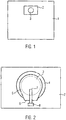
- FIG. 1 shows the schematic structure of an exemplary vacuum cleaner filter bag.
- the filter bag comprises a bag wall 1, a holding plate 2, as well as an inflow opening, through which the air to be filtered flows into the filter bag.
- the inflow opening is formed here by a passage opening 3 in the base plate of the holding plate 2 and a passage opening arranged in the bag wall 1 in alignment therewith.
- the holding plate 2 serves to fix the vacuum cleaner filter bag in a corresponding holder in a housing of a vacuum cleaner.
- the bag wall 1 comprises at least one nonwoven fabric layer, for example of a melt-spun fine fiber spunbonded nonwoven fabric (meltblown nonwoven fabric) or a spunbonded nonwoven spunbonded nonwoven fabric.
- a melt-spun fine fiber spunbonded nonwoven fabric meltblown nonwoven fabric
- a spunbonded nonwoven spunbonded nonwoven fabric spunbonded nonwoven fabric
- the holding plate 2 comprises a base plate made of a thermoplastic material.
- recycled plastic material such as recycled polypropylene (rPP) or recycled polyethylene terephthalate (rPET) may be used for the baseplate.
- recycled plastic used for the purposes of the present invention is synonymous with plastic recyclates.
- plastic recyclates For a conceptual definition reference is made to the standard DIN EN 15347: 2007.
- FIG. 2 A plan view of an exemplary holding plate used in conjunction with a filter bag as in FIG. 1 can be used as shown in FIG. 2 shown. This is the holding plate 2 with through opening 3 can be seen.
- the base plate of the holding plate 2 is here shown schematically rectangular, but may have any shapes that can correspond in particular with the corresponding holding device in the vacuum cleaner housing.
- the sealing element 4 is intended to prevent or limit the escape of dust from the vacuum cleaner filter bag by sealing the area between the edge of the passage opening 3 and the outside of a connecting piece of the vacuum cleaner.
- the sealing element 4 comprises a passage opening which overlaps the passage opening 3 of the base plate. Since the surface of the passage opening in the sealing element 4 is smaller than the surface of the passage opening 3 of the base plate, an annular sealing lip is formed which projects beyond the edge of the passage opening 3 of the base plate inwards, ie towards the center of the passage opening 3.
- the sealing element 4 is welded to the base plate and comprises at least one extruded thermoplastic elastomer TPE sheet bonded to the base plate.
- a film is an element whose thickness is substantially less than its extent perpendicular thereto (length and width).
- the film may have a, in particular constant, thickness of less than 0.35 mm, for example 0.13 mm.
- the sealing element 4 can be produced from a thermoplastic elastomer having a low melt flow index, in particular a melt flow index of less than 10 g / 10 min.
- the melt flow index or melt flow index is defined according to ISO 1133 and is measured by means of a capillary rheometer.
- the melt flow index indicates the mass of the thermoplastic melt which is forced in 10 minutes under a predetermined pressurization by a predetermined nozzle.
- the at least one extruded film may be a blown film or a cast film.
- the sealing element 4 may have a greater roughness on the side with which it comes in contact with the nozzle of the vacuum cleaner in operation, as on the opposite side. This can be achieved by imparting a surface structure to the film by calendering.
- the sealing element 4 may also comprise a plurality of layers of extruded films, wherein the layers may consist of a single or of different plastics.
- the layer to be connected to the base plate may in particular comprise a plastic which is compatible with the plastic material of the base plate, so that a secure welded connection can be produced.
- FIG. 2 also shows an optional closure flap 5, which is pivotable about a hinge 6.
- the joint 6 is in particular a film hinge.
- the closure flap 5 serves to close the passage opening 3 when the vacuum cleaner is not in operation, in particular when the filter bag is removed from the vacuum cleaner.
- the closure flap 3 can likewise be formed from a recycled plastic material, for example from the same material as the base plate.
- the closure flap 5 is biased by a spring element 7 in the closed position.
- the spring element 7 may consist of a Kunststoffneumaterial which is molded onto the closure flap 5.
- other known spring elements such as a metallic leaf spring, find use.
- a spring pocket 8 is provided, which corresponds to the EP 1 849 392 A1 can be trained.
- the spring element 7 is arranged in the closing direction in front of the closure flap 5.
- the top view of FIG. 2 takes place on the side of the holding plate 2, which is to be connected to the bag wall 1.
- the spring element 7 is therefore located after connecting the holding plate 2 with the vacuum cleaner filter bag in the dust chamber, ie in the interior of the filter bag.
Landscapes
- Engineering & Computer Science (AREA)
- Mechanical Engineering (AREA)
- Filters For Electric Vacuum Cleaners (AREA)
Abstract
Description
- Die Erfindung betrifft eine Halteplatte für einen Staubsaugerfilterbeutel, wobei die Halteplatte eine Grundplatte mit einer darin angeordneten Durchtrittsöffnung und ein Dichtungselement, welches am Rand der Durchtrittsöffnung angeordnet ist, umfasst.
- Derartige Halteplatten sind in vielfältiger Form bekannt, um einen damit verbundenen Staubsaugerfilterbeutel in einem Staubsaugergehäuse anzuordnen. Im Betrieb wird üblicherweise ein Stutzen des Staubsaugers in die Durchtrittsöffnung der Grundplatte eingeführt, um den Saugluftstrom in den Beutel zu leiten. Da Halteplatten üblicherweise für verschiedene Stutzendurchmesser passend sein müssen, sehen viele Lösungen eine elastische Dichtung (Dichtring) vor, welche die Durchmesserunterschiede der Stutzen ausgleichen soll. Üblicherweise wird das Dichtungselement durch eine Dichtlippe aus einem thermoplastischen Elastomer, TPE, gebildet, welche am Rand der Durchtrittsöffnung der Grundplatte angespritzt ist. Es ist jedoch auch bekannt, das Beutelmaterial des Staubsaugerfilterbeutels selbst als Dichtring zu benutzen, wie dies beispielsweise in der
DE 102 03 460 offenbart ist. Auch die Verwendung einer Dichtmembran zwischen Halteplatte 2 und Beutelwand 1, wie in derEP 2 044 874 offenbart, ist möglich. - Es hat sich herausgestellt, dass die Elastizität der verwendeten Dichtungselemente häufig nicht ausreichend ist, um eine ausreichende Dichtwirkung sicherzustellen. Es kann daher zu einer Undichtigkeit zwischen Stutzen und Dichtungselement kommen.
- Aufgabe der Erfindung ist es daher, eine Halteplatte mit einem Dichtungselement bereitzustellen, welches eine sichere Abdichtung im Betrieb gewährleistet.
- Diese Aufgabe wird durch eine Halteplatte gemäß Anspruch 1 gelöst. Besonders vorteilhafte Weiterbildungen finden sich in den Unteransprüchen.
- Gemäß der Erfindung ist es also vorgesehen, dass das Dichtungselement wenigstens eine extrudierte Folie aus einem thermoplastischen Elastomer, TPE, umfasst. Es hat sich gezeigt, dass solche extrudierten Folien geeigneter sind als bekannte Dichtungselemente, insbesondere angespritzt TPE Dichtlippen. Auch kann die Folie deutlich dünner ausgebildet werden als spritzgegossene Dichtlippen, weil flache und langgestreckte Kavitäten im Spritzgussverfahren nicht zuverlässig gefüllt werden können. Durch das anspruchsgemäße Dichtungselement ist es also möglich, eine zuverlässige Abdichtung des im Betrieb in die Durchtrittsöffnung eingeführten Stutzens zu ermöglichen.
- Die Halteplatte kann an eine Halteeinrichtung in einem Staubsaugergehäuse anbringbar sein. Dadurch kann die Halteplatte im Staubsaugergehäuse in einer vorbestimmten Position anordenbar, insbesondere fixierbar, sein. Alternativ kann der Staubsaugerfilterbeutel mithilfe der Halteplatte über einen staubsaugerseitigen Anschlussstutzen schiebbar sein.
- "Am Rand der Durchtrittsöffnung angeordnet" bedeutet hierin, dass das Dichtungselement wenigstens teilweise über den Rand der Durchtrittsöffnung zur Durchtrittsöffnung hin hinausragt und damit wenigstens teilweise mit der Durchtrittsöffnung überlappt. Das Dichtungselement bildet also eine Dichtlippe für die Durchtrittsöffnung der Grundplatte. Dadurch kann ein in die Durchtrittsöffnung eingeführter Stutzen eines Staubsaugers mit dem Dichtungselement in Kontakt kommen.
- Das Dichtungselement kann in derselben Ebene wie die Grundplatte, insbesondere wie die Durchtrittsöffnung angeordnet sein. In diesem Fall kann das Dichtungselement also teilweise oder vollständig entlang des Umfangs der Durchtrittsöffnung angeordnet sein.
- Es ist jedoch auch möglich, dass das Dichtungselement in einer Ebene angeordnet ist, welche parallel zur Ebene der Durchtrittsöffnung angeordnet ist. Das Dichtungselement kann dabei insbesondere auf der Seite der Grundplatte angeordnet sein, welche zum Verbinden mit der Beutelwand eines Staubsaugerfilterbeutels dient.
- Das Dichtungselement weist ebenfalls eine Durchtrittsöffnung auf, welche insbesondere konzentrisch zur Durchtrittsöffnung in der Grundplatte angeordnet sein kann. Die Fläche der Durchtrittsöffnung im Dichtungselement ist dabei geringer als die Fläche der Durchtrittsöffnung in der Grundplatte. Dadurch kann gewährleistet werden, dass ein Stutzen des Staubsaugers im Betrieb mit dem Dichtungselement in Kontakt kommt, wenn dieser in die Durchtrittsöffnung der Grundplatte eingeführt wird.
- Im Falle einer kreisförmigen Durchtrittsöffnung in der Grundplatte kann die Durchtrittsöffnung im Dichtungselement ebenfalls kreisförmig ausgebildet sein. Der Innendurchmesser der Durchtrittsöffnung im Dichtungselement ist in diesem Fall geringer als der Innendurchmesser der Durchtrittsöffnung in der Grundplatte. Im Falle einer anders geformten Durchtrittsöffnung kann der Innendurchmesser durch die maximale Ausdehnung in der Ebene der Durchtrittsöffnung ersetzt werden. Die maximale Ausdehnung der Durchtrittsöffnung im Dichtungselement ist in diesem Fall also geringer als die maximale Ausdehnung der Durchtrittsöffnung in der Grundplatte. Die Durchtrittsöffnung in der Grundplatte und die Durchtrittsöffnung im Dichtungselement können die gleiche oder eine unterschiedliche Form aufweisen.
- Im einfachsten Fall ist das Dichtungselement ringförmig ausgebildet. Es ist jedoch auch jede beliebige andere Form denkbar, solange eine Durchtrittsöffnung im Dichtungselement wenigstens teilweise mit der Durchtrittsöffnung in der Grundplatte überlappt, damit ein Stutzen eines Staubsaugers in die Durchtrittsöffnung in der Grundplatte und die Durchtrittsöffnung im Dichtungselement einführbar ist.
- Auch die Grundplatte kann beliebige Formen aufweisen, die insbesondere mit der entsprechenden Halteeinrichtung im Staubsaugergehäuse korrespondieren können. Die Grundplatte ist aber allgemein ein flächiges Bauteil, wobei insbesondere die Dicke der Grundplatte deutlich geringer ist als die Ausdehnung der Grundplatte in einer Ebene senkrecht dazu (Länge/Breite).
- Die wenigstens eine extrudierte Folie kann eine Blasfolie oder eine Gießfolie sein.
- Die wenigstens eine extrudierte Folie kann eine erste Seite und eine gegenüberliegende, zweite Seite aufweisen, wobei die erste Seite eine größere Rauheit als die zweite Seite aufweist. Die erste Seite mit der größeren Rauheit kann im Betrieb der Halteplatte so angeordnet sein, dass sie mit dem Stutzen des Staubsaugers, der in die Durchtrittsöffnung eingeführt wird, in Kontakt kommt. Die zweite Seite mit der geringeren Rauheit kann dagegen von der Oberfläche des Stutzens weg weisen, insbesondere zum Staubraum eines mit der Halteplatte verbundenen Filterbeutels hin. Dadurch kann erreicht werden, dass der Stutzen einfacher in die Durchtrittsöffnung eingeführt werden kann. Eine zu glatte Oberfläche des Dichtungselements könnte nämlich dazu führen, dass der Stutzen gewissermaßen am Dichtungselement klebt und daher eine hohe Haftreibung überwunden werden muss, um den Stutzen einzuführen. An der glatteren zweiten Seite kann dagegen Sauggut aufgrund der geringeren Rauheit schwerer anhaften, so dass sich ein unerwünschter Filterkuchen im Bereich der Durchtrittsöffnung nicht oder weniger stark ausbildet.
- Der Meltflowindex (Schmelzflussindex) des thermoplastischen Elastomers der wenigstens einen extrudierten Folie kann kleiner als 10 g/10min, insbesondere kleiner als 5 g/10min, insbesondere kleiner als 3 g/10min sein. Damit ist der Meltflowindex deutlich geringer als der von Kunststoffen, die beim Spritzgussverfahren eingesetzt werden. Bei Spritzgussverfahren sind nämlich Kunststoffe mit einem Meltflowindex von mehr als 40 g/10min nötig.
- Die Dicke der wenigstens einen extrudierten Folie kann kleiner als 0,35 mm, insbesondere kleiner als 0,25 mm, insbesondere kleiner als 0,15 mm betragen. Die Dicke der Folie kann dabei insbesondere konstant sein. Derartige dünne Strukturen können im Spritzgussverfahren nicht hergestellt werden, weil die dafür erforderlichen flachen und langgestreckten Kavitäten nicht gefüllt werden könnten. Im Spritzgussverfahren lassen sich daher nur Strukturen, insbesondere Dichtungselemente, mit einer Dicke von mehr als 0,4 mm herstellen.
- Die wenigstens eine extrudierte Folie kann mit der Grundplatte verbunden, insbesondere verschweißt sein. Die wenigstens eine extrudierte Folie kann dabei entweder unmittelbar oder über eine Verbindungsschicht, welche insbesondere einen Vliesstoff umfasst, mit der Grundplatte verbunden, insbesondere (ultraschall-)verschweißt sein. Eine Verbindungsschicht kann beispielsweise dann Anwendung finden, wenn das Kunststoffmaterial der Grundplatte mit dem Kunststoffmaterial des Dichtungselements unverträglich ist. In letzterem Fall würde sich das Kunststoffmaterial der Grundplatte im Wesentlichen nicht mit dem Kunststoffmaterial des Dichtungselements vermischen, so dass diese Kunststoffe nicht unmittelbar miteinander verschweißbar wären.
- Das Dichtungselement kann auch mehrere Lagen extrudierter Folien aus einem thermoplastischen Elastomer, TPE, umfassen (insbesondere durch Koextrusion hergestellt). Dadurch kann also ein mehrlagiges Dichtungselement bereitgestellt werden. Es ist auch möglich, eine oder mehrere Lagen extrudierter Folien aus einem thermoplastischen Elastomer, TPE, mit einer oder mehreren Lagen Vliesstoff zu einem Dichtungselement verbinden.
- In jeder der Lagen kann dann eine Durchtrittsöffnung angeordnet sein, wobei die Durchtrittsöffnungen koaxial angeordnet sind und so die Durchtrittsöffnung des Dichtungselements bilden. Der Durchmesser der Durchtrittsöffnungen in den einzelnen Lagen kann gleich oder unterschiedlich groß ausgebildet sein.
- Wenigstens zwei der Lagen extrudierter Folien können aus unterschiedlichen Kunststoffen bestehen. Es ist insbesondere möglich, die der Grundplatte zugewandte Lage aus einem Kunststoffmaterial zu bilden, welches vorteilhaft mit der Grundplatte (ultraschall-)verschweißt werden kann. Die eine oder mehrere weiteren Lagen können dagegen beispielsweise auf Elastizität und damit ausreichende Dichtwirkung hin optimiert sein.
- Die mehreren Lagen extrudierter Folien (gegebenenfalls mit einer oder mehreren Lagen Vliesstoff) können miteinander verbunden, insbesondere verschweißt oder verklebt sein. Die mehreren Lagen können insbesondere in einem Bereich miteinander verbunden sein, in dem das Dichtungselement nicht auch mit der Grundplatte verbunden ist. Somit können die Lagen des Dichtungselements bereits vor dem Verbinden mit der Grundplatte miteinander verbunden sein, was die Herstellung erleichtert, da nicht mehrere Lagen des Dichtungselements, jeweils mit Durchtrittsöffnung, zueinander und zur Grundplatte und dessen Durchtrittsöffnung positioniert werden müssen.
- Wenn zwei oder mehr Lagen extrudierter Folien oder wenigstens eine Lage einer extrudierten Folie zusammen mit wenigstens einer Lage Vliesstoff eingesetzt werden, können die Durchmesser der Durchtrittsöffnungen in den einzelnen Lagen gleich oder unterschiedlich groß ausgebildet sein.
- Wenn beide Durchtrittsöffnungen gleich groß sind, kann die Vliesstofflage zum Stutzen hin angeordnet sein. Die raue Oberfläche des Vliesstoffes hat dann eine ähnliche Wirkung wie die Aufrauhung der einen Folienseite, wie oben beschrieben. Die Durchmesser der Durchtrittsöffnungen können auch unterschiedlich sein. Somit lässt sich noch eine bessere Anpassung an verschiedene Stutzendurchmesser erreichen. So kann es hilfreich sein, wenn die Folie mit dem kleineren Durchmesser der Durchtrittsöffnung eine hohe Elastizität hat und gegebenenfalls eine geringe Dicke während die Folie mit dem größeren Durchmesser der Durchtrittsöffnung eine geringere Elastizität aufweist und eine größere Dicke, um somit zusätzlich eine Zentrierfunktion des Stutzens in der Durchtrittsöffnung zu übernehmen.
- Bei einer Vliesstofflage kann es - insbesondere wenn der Öffnungsdurchmesser der Durchtrittsöffnung kleiner ist als der der angrenzenden Folienlage - hilfreich sein, den Rand des Vliesstoffes mehrfach einzuschneiden.
- Die Grundplatte kann einen thermoplastischen Kunststoff umfassen oder daraus bestehen.
- Der thermoplastische Kunststoff kann insbesondere ein rezyklierter Kunststoff sein, beispielsweise rezykliertes Polyethylenterephthalat, rPET. Das rPET kann beispielsweise aus Getränkeflaschen (bottle flake chips) oder metallisierten PET-Folien stammen. Alternativ oder zusätzlich kann auch rezykliertes Polybutylenterephthalat (rPBT), rezyklierte Polymilchsäure (rPLA), rezykliertes Polyglycolid und/oder rezykliertes Polycaprolacton Verwendung finden. Auch rezyklierte Polyolefine, insbesondere rezykliertes Polypropylen (rPP), rezykliertes Polyethylen und/oder rezykliertes Polystyrol (rPS); rezykliertes Polyvinylchlorid (rPVC), rezyklierte Polyamiden sowie Mischungen und Kombinationen hiervon sind möglich.
- Die Grundplatte kann ein Stanzteil, Tiefziehteil oder ein Spritzgussteil sein. Mit anderen Worten kann die Grundplatte durch Stanzen, Tiefziehen (Thermoformen) oder Spritzgießen hergestellt worden sein.
- Die Erfindung stellt außerdem einen Staubsaugerfilterbeutel bereit, umfassend eine Beutelwand und eine damit verbundene, oben beschriebene Halteplatte.
- Die Halteplatte kann somit eines oder mehrere der oben genannten Merkmale aufweisen.
- Die Beutelwand des Staubsaugerfilterbeutels kann eine oder mehrere Filtermateriallagen, insbesondere eine oder mehrere Vliesstofflagen umfassen. Staubsaugerfilterbeutel mit einer derartigen Beutelwand aus mehreren Filtermateriallagen sind beispielsweise aus der
EP 2 011 556 oder derEP 0 960 645 bekannt. Als Material für die Vliesstofflagen können verschiedenste Kunststoffe verwendet werden, beispielsweise Polypropylen und/oder Polyester. Insbesondere die mit der Halteplatte zu verbindende Lage der Beutelwand kann eine Vliesstofflage sein. Die Beutelwand des Staubsaugerfilterbeutels kann ebenfalls Kunststoff-Recyclat umfassen oder daraus bestehen. Beispielsweise kann die Beutelwand wie in derEP 3 219 376 A1 beschrieben ausgebildet sein. Die Beutelwand kann über das Dichtungselement mit der Grundplatte verbunden, insbesondere verschweißt sein. Dadurch können Beutelwand und Dichtungselement gemeinsam mit der Halteplatte, insbesondere der Grundplatte, verbunden werden, was die Herstellung vereinfacht. - Der Begriff Vliesstoff ("Nonwoven") wird gemäß der Definition nach ISO Standard ISO9092:1988 bzw. CEM Standard EN29092 verwendet. Insbesondere sind die Begriffe Faservlies oder Vlies und Vliesstoff auf dem Gebiet der Herstellung von Vliesstoffen wie folgt gegeneinander abgegrenzt und auch im Sinne der vorliegenden Erfindung so zu verstehen. Zur Herstellung eines Vliesstoffes werden Fasern und/oder Filamente verwendet. Die lockeren oder losen und noch ungebundenen Fasern und/oder Filamente werden als Vlies oder Faservlies (Web) bezeichnet. Durch einen sog. Vliesbindeschritt entsteht aus einem derartigen Faservlies schließlich ein Vliesstoff, der eine ausreichende Festigkeit aufweist, um z.B. zu Rollen aufgewickelt zu werden. Mit anderen Worten wird ein Vliesstoff durch die Verfestigung selbsttragend ausgebildet. (Details zur Verwendung der hierin beschriebenen Definitionen und/oder Verfahren lassen sich auch dem Standardwerk "Vliesstoffe", W. Albrecht, H. Fuchs, W. Kittelmann, Wiley-VCH, 2000, entnehmen.)
- Die Beutelwand kann eine Durchgangsöffnung aufweisen, insbesondere wobei die Durchgangsöffnung der Beutelwand fluchtend zur Durchtrittsöffnung der Grundplatte angeordnet ist. Durch die Durchtrittsöffnung in der Grundplatte und die Durchgangsöffnung in der Beutelwand kann eine Einströmöffnung gebildet werden, durch welche die zu reinigende Luft in das Innere des Staubsaugerfilterbeutels strömen kann.
- Die Erfindung stellt außerdem ein Verfahren zum Herstellen einer Halteplatte bereit, umfassend Bereitstellen eines Dichtungselements, das wenigstens eine extrudierte Folie aus einem thermoplastischen Elastomer, TPE, umfasst, und Verbinden des Dichtungselements mit einer Grundplatte, sodass das Dichtungselement am Rand einer Durchtrittsöffnung der Grundplatte angeordnet wird.
- Die so hergestellte Halteplatte kann eines oder mehrere der oben genannten Merkmale aufweisen.
- Weitere Merkmale und Vorteile der Erfindung werden nachfolgend anhand der beispielhaften Figuren beschrieben. Dabei zeigt:
- Figur 1
- schematisch den Aufbau eines beispielhaften Staubsaugerfilterbeutels; und
- Figur 2
- den schematischen Aufbau einer beispielhaften Halteplatte in einer Draufsicht.
-
Figur 1 zeigt den schematischen Aufbau eines beispielhaften Staubsaugerfilterbeutels. Der Filterbeutel umfasst eine Beutelwand 1, eine Halteplatte 2, sowie eine Einströmöffnung, durch welche die zu filternde Luft in den Filterbeutel strömt. Die Einströmöffnung wird hier durch eine Durchtrittsöffnung 3 in der Grundplatte der Halteplatte 2 und eine fluchtend dazu angeordnete Durchgangsöffnung in der Beutelwand 1 gebildet. Die Halteplatte 2 dient der Fixierung des Staubsaugerfilterbeutels in einer korrespondierenden Halterung in einem Gehäuse eines Staubsaugers. - Die Beutelwand 1 umfasst wenigstens eine Vliesstofflage, beispielsweise aus einem schmelzgesponnenen Feinfaserspinnvliesstoff (Meltblownvliesstoff) oder einem Filamentspinnvliesstoff (Spunbond).
- Die Halteplatte 2 umfasst eine Grundplatte aus einem thermoplastischen Kunststoff. Beispielsweise kann rezykliertes Kunststoffmaterial, beispielsweise rezykliertes Polypropylen (rPP) oder rezykliertes Polyethylenterephthalat (rPET), für die Grundplatte verwendet werden.
- Für viele Kunststoff-Recyclate bestehen einschlägige internationale Normen. Für PET-Kunststoff-Recyclate ist beispielsweise die DIN EN 15353:2007 einschlägig.
- Der für die Zwecke der vorliegenden Erfindung verwendete Begriff "rezyklierter Kunststoff" ist dabei synonym zu verstehen zu Kunststoff-Recyclaten. Zur begrifflichen Definition wird hierbei auf die Norm DIN EN 15347:2007 verwiesen.
- Eine Draufsicht auf eine beispielhafte Halteplatte, die in Verbindung mit einem Filterbeutel wie in
Figur 1 dargestellt Verwendung finden kann, ist inFigur 2 gezeigt. Darin ist die Halteplatte 2 mit Durchtrittsöffnung 3 zu sehen. Die Grundplatte der Halteplatte 2 ist hier schematisch rechteckig dargestellt, kann jedoch beliebige Formen aufweisen, die insbesondere mit der entsprechenden Halteeinrichtung im Staubsaugergehäuse korrespondieren können. - In
Figur 2 ist außerdem ein am Rand der Durchtrittsöffnung 3 angeordnetes Dichtungselement 4 dargestellt. Das Dichtungselement 4 soll das Austreten von Staub aus dem Staubsaugerfilterbeutel vermeiden oder begrenzen, indem es den Bereich zwischen dem Rand der Durchtrittsöffnung 3 und der Außenseite eines Anschlussstutzens des Staubsaugers abdichtet. Dafür umfasst das Dichtungselement 4 eine Durchtrittsöffnung, welche die Durchtrittsöffnung 3 der Grundplatte überlappt. Da die Fläche der Durchtrittsöffnung im Dichtungselement 4 kleiner ist, als die Fläche der Durchtrittsöffnung 3 der Grundplatte, bildet sich eine ringförmige Dichtlippe, die über den Rand der Durchtrittsöffnung 3 der Grundplatte nach innen, also zur Mitte der Durchtrittsöffnung 3 hin, übersteht. - Das Dichtungselement 4 ist mit der Grundplatte verschweißt und umfasst wenigstens eine mit der Grundplatte verbundene extrudierte Folie aus einem thermoplastischen Elastomer, TPE.
- Als Folie wird ein Element bezeichnet, dessen Dicke wesentlich geringer ist als dessen Ausdehnung senkrecht dazu (Länge und Breite). Beispielsweise kann die Folie eine, insbesondere konstante, Dicke von weniger als 0,35 mm, beispielsweise 0,13 mm aufweisen.
- Im Gegensatz zu spritzgegossenen Dichtungselementen kann das Dichtungselement 4 aus einem thermoplastischen Elastomer mit einem geringen Meltflowindex, insbesondere einem Meltflowindex kleiner 10 g/10min, hergestellt werden. Der Meltflowindex oder Schmelzflussindex ist nach ISO 1133 definiert und wird mittels eines Kapillarrheometers gemessen. Der Schmelzflussindex gibt die Masse der Thermoplastschmelze an, die in 10 Minuten unter einer vorherbestimmten Druckbeaufschlagung durch eine vorherbestimmte Düse gedrückt wird.
- Die wenigstens eine extrudierte Folie kann eine Blasfolie oder eine Gießfolie sein.
- Es hat sich herausgestellt, dass derartige extrudierte Folien eine höhere Elastizität aufweisen als spritzgegossene Strukturen. Daher ist die Dichtwirkung des Dichtungselements 4 gegenüber spritzgegossenen Dichtlippen verbessert.
- Das Dichtungselement 4 kann auf der Seite, mit der es im Betrieb mit dem Stutzen des Staubsauers in Kontakt kommt, eine größere Rauheit aufweisen, als auf der gegenüberliegenden Seite. Dies kann dadurch erreicht werden, dass der Folie durch Kalandrieren eine Oberflächenstruktur aufgeprägt wird.
- Das Dichtungselement 4 kann auch mehrere Lagen extrudierter Folien umfassen, wobei die Lagen aus einem einheitlichen oder aus unterschiedlichen Kunststoffen bestehen können. Die mit der Grundplatte zu verbindende Lage kann insbesondere einen Kunststoff umfassen, der mit dem Kunststoffmaterial der Grundplatte verträglich ist, sodass eine sichere Schweißverbindung hergestellt werden kann.
-
Figur 2 zeigt außerdem eine optionale Verschlussklappe 5, welche um ein Gelenk 6 schwenkbar ist. Bei dem Gelenk 6 handelt es sich insbesondere um ein Filmscharnier. Die Verschlussklappe 5 dient dazu, die Durchtrittsöffnung 3 zu verschließen, wenn der Staubsauger nicht im Betrieb ist, insbesondere wenn der Filterbeutel aus dem Staubsauger entnommen wird. - Die Verschlussklappe 3 kann ebenfalls aus einem rezyklierten Kunststoffmaterial gebildet sein, beispielsweise aus demselben Material wie die Grundplatte.
- Die Verschlussklappe 5 wird durch ein Federelement 7 in Verschlussstellung vorgespannt. Das Federelement 7 kann aus einem Kunststoffneumaterial bestehen, das an die Verschlussklappe 5 angespritzt ist. Alternativ können auch andere bekannte Federelemente, beispielsweise eine metallische Blattfeder, Verwendung finden. Zur Beeinflussung der Federkennlinie ist eine Federtasche 8 vorgesehen, die entsprechend der
EP 1 849 392 A1 ausgebildet sein kann. - In diesem Beispiel ist das Federelement 7 in Schließrichtung gesehen vor der Verschlussklappe 5 angeordnet. Die Draufsicht der
Figur 2 erfolgt also auf die Seite der Halteplatte 2, die mit der Beutelwand 1 zu verbinden ist. Das Federelement 7 befindet sich daher nach dem Verbinden der Halteplatte 2 mit dem Staubsaugerfilterbeutel im Staubraum, also im Inneren des Filterbeutels. - Es versteht sich, dass in den zuvor beschriebenen Ausführungsbeispielen genannte Merkmale nicht auf diese speziellen Kombinationen beschränkt und auch in beliebigen anderen Kombinationen möglich sind. Weiterhin versteht es sich, dass in den Figuren gezeigte Geometrien nur beispielhaft sind und auch in beliebigen anderen Ausgestaltungen möglich sind.
Claims (12)
- Halteplatte (2) für einen Staubsaugerfilterbeutel umfassend:eine Grundplatte mit einer darin angeordneten Durchtrittsöffnung (3), undeinem Dichtungselement (4), welches am Rand der Durchtrittsöffnung (3) angeordnet ist,wobei das Dichtungselement (4) wenigstens eine extrudierte Folie aus einem thermoplastischen Elastomer, TPE, umfasst.
- Halteplatte nach Anspruch 1, wobei die wenigstens eine extrudierte Folie eine Blasfolie oder eine Gießfolie ist.
- Halteplatte nach Anspruch 1 oder 2, wobei die wenigstens eine extrudierte Folie eine erste Seite und eine gegenüberliegende, zweite Seite aufweist, wobei die erste Seite eine größere Rauheit als die zweite Seite aufweist.
- Halteplatte nach einem der vorangegangenen Ansprüche, wobei der Meltflowindex des thermoplastischen Elastomers der wenigstens einen extrudierten Folie ist kleiner als 10 g/10min, insbesondere kleiner als 5 g/10min, insbesondere kleiner als 3 g/10min.
- Halteplatte nach einem der vorangegangenen Ansprüche, wobei die Dicke der wenigstens einen extrudierten Folie kleiner als 0,35 mm, insbesondere kleiner als 0,25 mm, insbesondere kleiner als 0,15 mm, beträgt.
- Halteplatte nach einem der vorangegangenen Ansprüche, wobei die wenigstens eine extrudierte Folie mit der Grundplatte verschweißt ist.
- Halteplatte nach einem der vorangegangenen Ansprüche, wobei das Dichtungselement (4) mehrere Lagen extrudierter Folien aus einem thermoplastischen Elastomer, TPE, umfasst.
- Halteplatte nach Anspruch 7, wobei wenigstens zwei der Lagen extrudierter Folien aus unterschiedlichen Kunststoffen bestehen.
- Halteplatte nach einem der vorangegangenen Ansprüche, wobei die Grundplatte einen thermoplastischen Kunststoff umfasst oder daraus besteht.
- Halteplatte nach Anspruch 9, wobei der thermoplastische Kunststoff ein rezyklierter Kunststoff ist, beispielsweise rezykliertes Polyethylenterephthalat, rPET.
- Halteplatte nach einem der vorangegangenen Ansprüche, wobei die Grundplatte ein Stanzteil, ein Tiefziehteil oder ein Spritzgussteil ist.
- Staubsaugerfilterbeutel umfassend eine Halteplatte nach einem der vorangegangenen Ansprüche.
Priority Applications (9)
| Application Number | Priority Date | Filing Date | Title |
|---|---|---|---|
| EP18158393.1A EP3530171B1 (de) | 2018-02-23 | 2018-02-23 | Halteplatte mit dichtungselement |
| DK18158393.1T DK3530171T3 (da) | 2018-02-23 | 2018-02-23 | Holdeplade med tætningselement |
| ES18158393T ES2876182T3 (es) | 2018-02-23 | 2018-02-23 | Placa de sujeción con elemento de junta |
| PL18158393T PL3530171T3 (pl) | 2018-02-23 | 2018-02-23 | Płytka mocująca z elementem uszczelniającym |
| RU2020128181A RU2753074C1 (ru) | 2018-02-23 | 2019-02-20 | Удерживающая пластина с уплотнительным элементом |
| AU2019223037A AU2019223037B2 (en) | 2018-02-23 | 2019-02-20 | Retainer plate with a seal element |
| PCT/EP2019/054179 WO2019162307A1 (de) | 2018-02-23 | 2019-02-20 | Halteplatte mit dichtungselement |
| CN201980014160.2A CN111757696B (zh) | 2018-02-23 | 2019-02-20 | 具有密封元件的保持板 |
| US16/975,039 US12042117B2 (en) | 2018-02-23 | 2019-02-20 | Retainer plate with a seal element |
Applications Claiming Priority (1)
| Application Number | Priority Date | Filing Date | Title |
|---|---|---|---|
| EP18158393.1A EP3530171B1 (de) | 2018-02-23 | 2018-02-23 | Halteplatte mit dichtungselement |
Publications (2)
| Publication Number | Publication Date |
|---|---|
| EP3530171A1 true EP3530171A1 (de) | 2019-08-28 |
| EP3530171B1 EP3530171B1 (de) | 2021-04-07 |
Family
ID=61274183
Family Applications (1)
| Application Number | Title | Priority Date | Filing Date |
|---|---|---|---|
| EP18158393.1A Active EP3530171B1 (de) | 2018-02-23 | 2018-02-23 | Halteplatte mit dichtungselement |
Country Status (9)
| Country | Link |
|---|---|
| US (1) | US12042117B2 (de) |
| EP (1) | EP3530171B1 (de) |
| CN (1) | CN111757696B (de) |
| AU (1) | AU2019223037B2 (de) |
| DK (1) | DK3530171T3 (de) |
| ES (1) | ES2876182T3 (de) |
| PL (1) | PL3530171T3 (de) |
| RU (1) | RU2753074C1 (de) |
| WO (1) | WO2019162307A1 (de) |
Cited By (1)
| Publication number | Priority date | Publication date | Assignee | Title |
|---|---|---|---|---|
| EP3950087A1 (de) * | 2020-08-06 | 2022-02-09 | Eurofilters N.V. | Staubsaugerfilterbeutel aus recyclierten kunststoffen |
Citations (10)
| Publication number | Priority date | Publication date | Assignee | Title |
|---|---|---|---|---|
| DE19806452A1 (de) * | 1998-02-17 | 1999-08-26 | Nordenia Technologies Gmbh | Thermoplastische Folie mit elastischen Eigenschaften und Verfahren und Vorrichtung zur Herstellung derselben |
| EP0960645A2 (de) | 1998-05-11 | 1999-12-01 | Airflo Europe N.V. | Staubfilterbeutel für einen Staubsauger oder Filter, und Verfahren zum Filtern eines Gases |
| DE10203460A1 (de) | 2001-01-27 | 2002-08-29 | Wolf Gmbh | In einen Staubsauger einsetzbare Filtereinrichtung |
| DE202004008971U1 (de) * | 2004-06-05 | 2004-08-05 | Branofilter Gmbh | Staubfilterbeutel |
| DE102005041811A1 (de) * | 2005-09-02 | 2007-03-08 | BSH Bosch und Siemens Hausgeräte GmbH | Staubsaugerbeutel mit Kunststoffflansch |
| EP1849392A1 (de) | 2006-04-25 | 2007-10-31 | Eurofilters Holding N.V | Halteplatte für einen Staubsaugerfilterbeutel |
| EP2011556A1 (de) | 2007-07-06 | 2009-01-07 | Eurofilters Holding N.V | Staubsaugerfilterbeutel |
| EP2044874A2 (de) | 2007-10-01 | 2009-04-08 | BRANOfilter GmbH | Filterbeutel für Staubsauger |
| DE202008004025U1 (de) * | 2008-03-20 | 2009-08-06 | Wolf Pvg Gmbh & Co. Kg | Filter |
| EP3219376A1 (de) | 2016-03-17 | 2017-09-20 | Eurofilters N.V. | Staubsaugerfilterbeutel aus recyclierten kunststoffen |
Family Cites Families (127)
| Publication number | Priority date | Publication date | Assignee | Title |
|---|---|---|---|---|
| US2347899A (en) | 1942-09-05 | 1944-05-02 | John W Forsythe | Charging box for open hearth furnace charging operation |
| GB651916A (en) | 1948-06-15 | 1951-04-11 | Tissue Papers Ltd | Improvements in filter bags for suction cleaners |
| US3231089A (en) | 1963-01-24 | 1966-01-25 | Fram Corp | Filters |
| US3283481A (en) | 1964-12-18 | 1966-11-08 | Studley Paper Company Inc | Filter bag for vacuum cleaners and collar therefor |
| NL130590C (de) | 1966-07-13 | 1900-01-01 | ||
| SE334445B (de) | 1966-10-26 | 1971-04-26 | Electrolux Ab | |
| US3533868A (en) | 1967-02-15 | 1970-10-13 | Cons Foods Corp | Method of manufacturing end closures for a vacuum cleaner dust bag |
| US3401867A (en) | 1967-03-16 | 1968-09-17 | Continental Can Co | Self-closing dust valve for a disposable vacuum cleaner bag |
| DE2533590C2 (de) | 1975-07-26 | 1983-01-13 | Licentia Patent-Verwaltungs-Gmbh, 6000 Frankfurt | Filter für Staubsauger |
| DE7832780U1 (de) | 1978-11-04 | 1979-03-01 | Vorwerk & Co Interholding Gmbh, 5600 Wuppertal | Halteplatte fuer staubsaugerfilterbeutel |
| US4364757A (en) | 1981-08-24 | 1982-12-21 | The Hoover Company | Vacuum cleaner filter bag collar arrangement |
| EP0179950A1 (de) | 1984-11-01 | 1986-05-07 | Raymond Leslie Woodley | Dichtungsanordnungen |
| DE8622890U1 (de) | 1986-08-27 | 1987-12-23 | Siemens AG, 1000 Berlin und 8000 München | Filterbeutel für einen Staubsauger |
| DE3714780A1 (de) | 1987-05-04 | 1988-12-01 | Vorwerk Co Interholding | Elektro-staubsauger |
| DE8811821U1 (de) | 1988-09-17 | 1988-10-27 | Branofilter Gmbh, 8501 Dietenhofen | Anschlußstück eines Filtersacks |
| DE8812401U1 (de) | 1988-09-30 | 1990-02-01 | Siemens AG, 1000 Berlin und 8000 München | Staubaufnahmebehältnis für einen Staubsauger |
| GB8901320D0 (en) | 1989-01-21 | 1989-03-15 | Elopak Systems | Nozzle |
| US5039324A (en) | 1989-03-27 | 1991-08-13 | Mastercraft Industries, Inc. | Sealable collar vacuum cleaner bag |
| US4924923A (en) | 1989-05-17 | 1990-05-15 | Vernay Laboratories, Inc. | Fuel filler pipe seal |
| DE9016893U1 (de) | 1990-12-14 | 1991-03-07 | Gebrüder Voit, 8500 Nürnberg | Staubsaugereinsatzbeutel |
| DE9016939U1 (de) | 1990-12-17 | 1991-04-04 | Wolfgang B. Schroeter GmbH, 4973 Vlotho | Filtereinrichtung für einen Staubsauger |
| DE9101981U1 (de) | 1991-02-20 | 1991-05-08 | Omega Elektrogeräte GmbH, O-7400 Altenburg | Staubfilterbeutel |
| DE9110724U1 (de) | 1991-08-27 | 1991-11-07 | Schatzek, Ruth, 1000 Berlin | Wiederverschließbarer Staubbeutel für Staubsauger |
| DE9316626U1 (de) | 1993-10-30 | 1995-02-23 | Robert Bosch Gmbh, 70469 Stuttgart | Staubabsaugeeinrichtung für eine Handwerkzeugmaschine |
| DE4415350A1 (de) | 1994-05-02 | 1995-11-16 | Vorwerk Co Interholding | Staubfilterbeutel für einen Staubsauger |
| FR2721188B1 (fr) | 1994-06-21 | 1996-08-09 | Delphy | Dispositif de fermeture automatique d'un sac à poussière d'aspirateur par clapet. |
| US5688298A (en) | 1995-10-10 | 1997-11-18 | Home Care Industries, Inc. | Self-aligning, self-sealing vacuum bag |
| DE29614272U1 (de) | 1996-08-17 | 1996-09-26 | Gebrüder Voit, 90408 Nürnberg | Filter-Einsatz-Beutel, insbesondere für Staubsauger |
| DE29615163U1 (de) | 1996-08-31 | 1996-11-21 | Hafner, Ingo, Dipl.-Ing., 56566 Neuwied | Vorrichtung zur Aufnahme von Staub, Schmutz u.dgl. |
| EP1258277B1 (de) | 1998-05-11 | 2003-11-05 | Airflo Europe N.V. | Staubfilterbeutel für einen Staubsauger |
| DE29811799U1 (de) | 1998-07-02 | 1998-09-10 | FESTO Tooltechnic GmbH & Co., 73728 Esslingen | Filtersack für staubsaugende Geräte |
| DE29819699U1 (de) | 1998-11-04 | 1999-02-11 | Aichner Filter GmbH, 92345 Dietfurt | Halteplatte eines Staubsauger-Filterbeutels |
| DE19919809C2 (de) | 1999-04-30 | 2003-02-06 | Fibermark Gessner Gmbh & Co | Staubfilterbeutel, enthaltend Nanofaservlies |
| US6372004B1 (en) | 1999-07-08 | 2002-04-16 | Airflo Europe N.V. | High efficiency depth filter and methods of forming the same |
| DE19948909A1 (de) | 1999-10-11 | 2001-04-12 | Vorwerk Co Interholding | Filterbeutel für einen Staubsauger |
| DE20005448U1 (de) | 2000-03-20 | 2000-06-15 | Fa. City Service, Gent | Halteplatte eines Staubsauger-Filterbeutels |
| SE0001405D0 (sv) | 2000-04-13 | 2000-04-13 | Electrolux Ab | Dammbehållare |
| DE20010049U1 (de) | 2000-06-03 | 2000-09-14 | Aichner Filter GmbH, 92345 Dietfurt | Staubfilterbeutel, insbesondere für einen Staubsauger |
| DE10203405B4 (de) | 2001-01-27 | 2013-06-20 | Wolf Pvg Gmbh & Co. Kg | Filtervorrichtung für einen Staubsauger |
| DE10120223B4 (de) | 2001-04-24 | 2005-08-25 | Carl Freudenberg Kg | Mehrlagiger Luftfilter und dessen Verwendung |
| DE20200551U1 (de) * | 2002-01-09 | 2002-04-04 | Branofilter Gmbh | Anschlussstück eines Staubfilterbeutels |
| DE10209718A1 (de) | 2002-03-06 | 2003-09-25 | Edison Fatehpour | Federelement für eine Verschlussklappe einer Filtertüte |
| US6716262B2 (en) | 2002-04-02 | 2004-04-06 | The Scott Fetzer Company | Mounting collar for a filter bag |
| DE10221694B4 (de) | 2002-05-16 | 2018-07-12 | Branofilter Gmbh | Mehrlagiger Filteraufbau, Verwendung eines solchen mehrlagigen Filteraufbaus, Staubfilterbeutel, Taschenfilterbeutel, plissierter Filter, flächiger Abluftfilter und Luftfilter für Kraftfahrzeuge |
| US7338994B2 (en) * | 2002-10-01 | 2008-03-04 | Dow Global Technologies Inc. | Rheology-modified thermoplastic elastomer compositions for extruded profiles |
| DE20316574U1 (de) | 2003-10-28 | 2003-12-24 | Branofilter Gmbh | Anschlussstück eines Filterbeutels für staubsaugende Geräte |
| US7341612B2 (en) * | 2003-12-22 | 2008-03-11 | Znn Technologies, Llc | Disposable vacuum bags |
| DE102004030346A1 (de) * | 2004-06-18 | 2006-01-05 | Branofilter Gmbh | Staubfilterbeutel und zugeordnete Adapterplatte |
| TWI395567B (zh) | 2005-02-28 | 2013-05-11 | 松下電器產業股份有限公司 | Vacuum cleaners for electric vacuum cleaners and electric vacuum cleaners |
| DE202005007503U1 (de) | 2005-05-12 | 2006-09-21 | Melitta Haushaltsprodukte Gmbh & Co. Kg | Filterbeutel |
| DE102005027078B4 (de) | 2005-06-11 | 2007-12-13 | Jan-Robert Wulbrandt | Vorrichtung zur Befestigung von Filterbeuteln in Geräten |
| US7662200B2 (en) | 2005-10-18 | 2010-02-16 | Electrolux Home Care Products, Inc. | Vacuum bag mounting and viewing features |
| ES2305989T3 (es) | 2005-11-22 | 2008-11-01 | Eurofilters Holding N.V | Bolsa de filtro de aspirador de polvo con dispositivo deflector. |
| DE502006000799D1 (de) | 2005-11-22 | 2008-07-03 | Eurofilters Holding Nv | Staubsaugerfilterbeutel und verwendung eines staubsaugefilterbeutels |
| DE202005019004U1 (de) | 2005-12-06 | 2007-04-19 | Melitta Haushaltsprodukte Gmbh & Co. Kg | Filtermaterial und Staubsaugerbeutel |
| EP1795427B2 (de) | 2005-12-12 | 2014-09-24 | Inventus Engineering GmbH | Energie absorbierendes Element |
| DE102005059214B4 (de) | 2005-12-12 | 2007-10-25 | Eurofilters N.V. | Filterbeutel für einen Staubsauger |
| US7938276B2 (en) | 2006-02-01 | 2011-05-10 | Mechanical Manufacturing Corporation | Filtration architecture for optimized performance |
| DE102006017553B3 (de) | 2006-04-13 | 2007-12-27 | Eurofilters N.V. | Filterbeutel für einen Staubsauger |
| DE502007004328D1 (de) | 2006-04-25 | 2010-08-19 | Eurofilters Holding Nv | Halteplatte für einen staubsaugerfilterbeutel |
| DE102006037456A1 (de) | 2006-08-10 | 2008-02-14 | Vorwerk & Co. Interholding Gmbh | Filterbeutel für einen Staubsauger |
| DE202006016789U1 (de) | 2006-11-03 | 2006-12-28 | Branofilter Gmbh | Anschlussstück für einen Staubfilterbeutel sowie mit einem solchen Anschlussstück ausgestatteter Staubfilterbeutel |
| ES2361118T3 (es) | 2006-11-03 | 2011-06-14 | Eurofilters Holding N.V. | Bolsa de filtro de aspiradora antibacterial. |
| DE102006055890A1 (de) | 2006-11-27 | 2008-05-29 | Wolf Gmbh & Co. Kg | Verschlussvorrichtung für Filterbeutel und Verfahren zum Herstellen eines Filterbeutels mit einer Verschlussvorrichtung |
| JP4934464B2 (ja) | 2007-03-05 | 2012-05-16 | 大日本印刷株式会社 | 清掃用具 |
| DE102008046200B4 (de) | 2007-09-28 | 2016-09-15 | Vorwerk & Co. Interholding Gmbh | Filterbeutel für einen Staubsauger |
| DE102007053151B4 (de) | 2007-11-08 | 2025-05-08 | Wolf Pvg Gmbh & Co. Kommanditgesellschaft | Halteplatte für einen Staubsaugerbeutel und Verfahren zu deren Herstellung |
| DE102007057170A1 (de) | 2007-11-26 | 2009-05-28 | Papierverarbeitung Görlitz GmbH | Staubsaugerbeutel mit Kunststoff-Flansch |
| DE102007062028B4 (de) | 2007-12-21 | 2009-09-03 | Arwed Löseke Papierverarbeitung und Druckerei GmbH | Verfahren zur Herstellung eines Staubfilterbeutels und Staubfilterbeutel |
| DE202008001391U1 (de) | 2008-01-31 | 2009-06-04 | Wolf Pvg Gmbh & Co. Kg | Halteplatte für Staubsaugerbeutel |
| US20080127832A1 (en) | 2008-02-23 | 2008-06-05 | Yuejie Zhang | Transparent Foldable Dust Bag |
| ES2440722T3 (es) | 2008-03-07 | 2014-01-30 | Eurofilters Holding N.V. | Bolsa de filtro de aspiradora |
| DE202008003248U1 (de) | 2008-03-07 | 2008-05-08 | Eurofilters Holding N.V. | Staubsaugerfilterbeutel |
| US7972458B2 (en) | 2008-03-10 | 2011-07-05 | Uv Corporation | Filter material and process for producing same |
| US7794516B2 (en) | 2008-04-09 | 2010-09-14 | The Scott Fetzer Company | Filter bag mounting assembly |
| USD600868S1 (en) | 2008-05-02 | 2009-09-22 | The Scott Fetzer Company | Mounting collar for a filter bag |
| DE202008006904U1 (de) | 2008-05-21 | 2009-10-15 | Wolf Pvg Gmbh & Co. Kg | Halteplatte für einen Staubsaugerbeutel |
| DE202008004733U1 (de) | 2008-07-13 | 2008-10-02 | Wulbrandt, Herbert | Halteplatte für Staubsaugerbeutel mit automatischem Verschluss |
| DE102008041227A1 (de) | 2008-08-13 | 2010-02-18 | BSH Bosch und Siemens Hausgeräte GmbH | Staubsaugerbeutel |
| DE202008018054U1 (de) | 2008-08-29 | 2011-04-28 | Vorwerk & Co. Interholding Gmbh | Filterbeutel für einen Staubsauger |
| CN101747596A (zh) | 2008-12-11 | 2010-06-23 | 王世和 | 回收聚酯切片微丝制备方法和用途 |
| JP5396131B2 (ja) | 2009-04-03 | 2014-01-22 | ユニ・チャーム株式会社 | 吸収性物品製造装置、及び、吸収性物品を製造する方法 |
| EP2253351B1 (de) | 2009-04-28 | 2011-06-01 | Dräger Medical GmbH | Schlitzventil in Kombination mit einem pneumatischen Schaltkreis eines Beatmungsgeräts |
| EP2263508B1 (de) | 2009-06-19 | 2015-08-05 | Eurofilters N.V. | Flachbeutel für Staubsauger mit mindestens zwei Diffusoren |
| DE102009035717A1 (de) | 2009-07-31 | 2011-02-10 | Miele & Cie. Kg | Verfahren zur Anzeige eines Füllgrads eines Staubbeutels und Steuerungsvorrichtung zur Ausführung des Verfahrens |
| WO2011017457A2 (en) | 2009-08-04 | 2011-02-10 | The Xextex Corporation | High efficiency low pressure drop synthetic fiber based air filter made completely from post consumer waste materials |
| PL2301402T3 (pl) | 2009-09-25 | 2014-06-30 | Eurofilters Holding Nv | Płyta nośna do worka filtrującego odkurzacza |
| PL2311359T3 (pl) | 2009-10-19 | 2016-10-31 | Worek filtracyjny do odkurzacza | |
| EP2311358B1 (de) * | 2009-10-19 | 2015-12-23 | Eurofilters Holding N.V. | Halteplatte für einen Staubsaugerfilterbeutel |
| WO2011057641A1 (en) | 2009-11-13 | 2011-05-19 | Formfiber Denmark Aps | A non-woven fibre product comprising fibres of recycled material |
| DE202011102509U1 (de) | 2010-05-31 | 2011-11-04 | Aktiebolaget Electrolux | Staubbeutel für einen Staubsauger |
| DE102010031046A1 (de) | 2010-07-07 | 2012-01-12 | Alfred Kärcher Gmbh & Co. Kg | Reinigungsgerät |
| DE102010060175A1 (de) | 2010-09-06 | 2012-03-08 | Vorwerk & Co. Interholding Gmbh | Staubfilterbeutel |
| DE102010046567A1 (de) | 2010-09-27 | 2012-03-29 | Sandler Ag | Mehrlagiger Filteraufbau |
| DE102011008117A1 (de) | 2010-10-05 | 2012-04-05 | Herbert Wulbrandt | Verschluss einer Halteplatte für Staubsaugerbeutel und deren Fertigung |
| DE102010060353A1 (de) | 2010-11-04 | 2012-05-10 | Papierverarbeitung Görlitz GmbH | Staubfilterbeutel für Staubsauger |
| FR2970865B1 (fr) | 2011-01-31 | 2013-02-08 | Gibaud | Ceinture de soutien lombaire |
| DE102011105384A1 (de) | 2011-06-20 | 2012-12-20 | Alexander Patzig | Halteplatte für Staubsaugerbeutel |
| DE202011103174U1 (de) | 2011-07-14 | 2011-10-17 | Branofilter Gmbh | Staubsaugerfilterbeutel mit Halteplatte ausVliesstoff |
| DE202011052208U1 (de) | 2011-12-06 | 2013-03-08 | Wolf Pvg Gmbh & Co. Kg | Haltevorrichtung für einen Staubsaugerbeutel |
| ES2534100T3 (es) * | 2011-12-22 | 2015-04-17 | Eurofilters N.V. | Placa de sujeción |
| US20130177264A1 (en) | 2012-01-10 | 2013-07-11 | Fka Distributing Co., Llc | Fabric And Method of Producing Same |
| DE102012012999B4 (de) | 2012-01-24 | 2017-06-14 | Elku Bauteile GmbH | Halteplatte für Staubsaugerbeutel mit automatischem Verschluss mit einem elastischen Element |
| CN202730890U (zh) | 2012-08-08 | 2013-02-13 | 浙江搏正铜业有限公司 | 一种下水器防臭套 |
| US9211491B2 (en) | 2012-11-06 | 2015-12-15 | Lydall, Inc. | Air filtration media and processes for manufacturing the same |
| DE202013001096U1 (de) | 2013-02-05 | 2013-03-05 | Branofilter Gmbh | Staubfilterbeutel für Staubsauger |
| DE202013100862U1 (de) | 2013-02-28 | 2013-03-13 | Wolf Pvg Gmbh & Co. Kg | Halteplatte für einen Staubsaugerbeutel |
| DE202013103508U1 (de) | 2013-08-05 | 2013-08-22 | Wolf Pvg Gmbh & Co. Kg | Staubsaugerbeutel |
| DE202014100563U1 (de) | 2014-02-10 | 2015-05-15 | Wolf Pvg Gmbh & Co. Kg | Staubsaugerbeutel |
| EP2929822B1 (de) | 2014-04-08 | 2017-02-22 | Eurofilters N.V. | Staubsaugerfilterbeutel für einen upright-staubsauger |
| PL3047777T3 (pl) | 2015-01-20 | 2020-05-18 | Eurofilters Holding N.V. | Robot odkurzający |
| DE202015101218U1 (de) | 2015-03-10 | 2015-04-01 | Branofilter Gmbh | Staubfilterbeutel zum Einsatz in einem Staubsauggerät |
| CN204654815U (zh) * | 2015-05-28 | 2015-09-23 | 湖州市练市美乐家庭用品制造厂 | 自动密封的吸尘器尘袋密封装置 |
| ES2916748T3 (es) | 2015-12-12 | 2022-07-05 | Procedimiento para producir una unión por material entre una placa de retención y la pared de una bolsa de filtro de aspiradora, así como bolsa de filtro de aspiradora | |
| DE202015008776U1 (de) * | 2015-12-22 | 2016-01-29 | Eurofilters N.V. | Staubsaugerfilterbeutel mit stoffschlüssig verbundener Halteplatte |
| EP3219373B1 (de) | 2016-03-17 | 2018-03-07 | Eurofilters N.V. | Staubsaugerfilterbeutel mit recyclierten textilmaterialien und/oder baumwolllinters |
| EP3219374B1 (de) | 2016-03-17 | 2019-05-08 | Eurofilters N.V. | Staubsaugerfilterbeutel aus recyclierten kunststoffen |
| CN109152504B (zh) | 2016-05-09 | 2022-05-10 | 伊莱克斯公司 | 用于真空吸尘器灰尘容器的连接板以及灰尘容器 |
| CN109068915B (zh) | 2016-05-09 | 2021-08-13 | 伊莱克斯公司 | 用于真空吸尘器的灰尘容器 |
| DE202016003890U1 (de) | 2016-06-22 | 2016-07-06 | Elku Bauteile GmbH | Halteplatte für einen Staubsaugerbeutel mit einer Dichtung die mit einer Verschlussklappe zusammenwirkt |
| AU2016430486B2 (en) | 2016-11-23 | 2023-06-15 | Aktiebolaget Electrolux | Holder for vacuum cleaner dust container |
| HUE069931T2 (hu) | 2016-11-23 | 2025-04-28 | Electrolux Ab | Porszívó porgyûjtõ tartályának eszközei |
| DK3338610T3 (da) | 2016-12-23 | 2020-04-20 | Eurofilters Holding Nv | Holdeplade til en støvsugerpose med tætning |
| CN207270312U (zh) | 2017-04-11 | 2018-04-27 | 苏州欧圣电气股份有限公司 | 吸尘器 |
| US10821712B2 (en) * | 2017-06-13 | 2020-11-03 | Exxonmobil Chemical Patents Inc. | Low crystalline polypropylene-based polymer for blown film applications |
| DE102018101075A1 (de) | 2018-01-18 | 2019-07-18 | Vorwerk & Co. Interholding Gmbh | Filter mit einem Filterinnenraum zur Aufnahme von Sauggut |
| DE102020103084A1 (de) | 2020-02-06 | 2021-08-12 | Watermann Polyworks Gmbh | Dichtelement für eine Gebäudestruktur, Verfahren zur Herstellung eines Dichtelements und Gebäudestruktur mit Dichtelement |
-
2018
- 2018-02-23 PL PL18158393T patent/PL3530171T3/pl unknown
- 2018-02-23 ES ES18158393T patent/ES2876182T3/es active Active
- 2018-02-23 DK DK18158393.1T patent/DK3530171T3/da active
- 2018-02-23 EP EP18158393.1A patent/EP3530171B1/de active Active
-
2019
- 2019-02-20 CN CN201980014160.2A patent/CN111757696B/zh active Active
- 2019-02-20 RU RU2020128181A patent/RU2753074C1/ru active
- 2019-02-20 AU AU2019223037A patent/AU2019223037B2/en active Active
- 2019-02-20 WO PCT/EP2019/054179 patent/WO2019162307A1/de not_active Ceased
- 2019-02-20 US US16/975,039 patent/US12042117B2/en active Active
Patent Citations (10)
| Publication number | Priority date | Publication date | Assignee | Title |
|---|---|---|---|---|
| DE19806452A1 (de) * | 1998-02-17 | 1999-08-26 | Nordenia Technologies Gmbh | Thermoplastische Folie mit elastischen Eigenschaften und Verfahren und Vorrichtung zur Herstellung derselben |
| EP0960645A2 (de) | 1998-05-11 | 1999-12-01 | Airflo Europe N.V. | Staubfilterbeutel für einen Staubsauger oder Filter, und Verfahren zum Filtern eines Gases |
| DE10203460A1 (de) | 2001-01-27 | 2002-08-29 | Wolf Gmbh | In einen Staubsauger einsetzbare Filtereinrichtung |
| DE202004008971U1 (de) * | 2004-06-05 | 2004-08-05 | Branofilter Gmbh | Staubfilterbeutel |
| DE102005041811A1 (de) * | 2005-09-02 | 2007-03-08 | BSH Bosch und Siemens Hausgeräte GmbH | Staubsaugerbeutel mit Kunststoffflansch |
| EP1849392A1 (de) | 2006-04-25 | 2007-10-31 | Eurofilters Holding N.V | Halteplatte für einen Staubsaugerfilterbeutel |
| EP2011556A1 (de) | 2007-07-06 | 2009-01-07 | Eurofilters Holding N.V | Staubsaugerfilterbeutel |
| EP2044874A2 (de) | 2007-10-01 | 2009-04-08 | BRANOfilter GmbH | Filterbeutel für Staubsauger |
| DE202008004025U1 (de) * | 2008-03-20 | 2009-08-06 | Wolf Pvg Gmbh & Co. Kg | Filter |
| EP3219376A1 (de) | 2016-03-17 | 2017-09-20 | Eurofilters N.V. | Staubsaugerfilterbeutel aus recyclierten kunststoffen |
Cited By (2)
| Publication number | Priority date | Publication date | Assignee | Title |
|---|---|---|---|---|
| EP3950087A1 (de) * | 2020-08-06 | 2022-02-09 | Eurofilters N.V. | Staubsaugerfilterbeutel aus recyclierten kunststoffen |
| WO2022029071A1 (de) * | 2020-08-06 | 2022-02-10 | Eurofilters N.V. | Staubsaugerfilterbeutel aus recyclierten kunststoffen |
Also Published As
| Publication number | Publication date |
|---|---|
| CN111757696A (zh) | 2020-10-09 |
| AU2019223037A1 (en) | 2020-09-03 |
| PL3530171T3 (pl) | 2021-10-18 |
| EP3530171B1 (de) | 2021-04-07 |
| CN111757696B (zh) | 2022-01-11 |
| DK3530171T3 (da) | 2021-06-14 |
| US20200390304A1 (en) | 2020-12-17 |
| AU2019223037B2 (en) | 2021-10-14 |
| US12042117B2 (en) | 2024-07-23 |
| WO2019162307A1 (de) | 2019-08-29 |
| RU2753074C1 (ru) | 2021-08-11 |
| ES2876182T3 (es) | 2021-11-12 |
Similar Documents
| Publication | Publication Date | Title |
|---|---|---|
| EP2311358B1 (de) | Halteplatte für einen Staubsaugerfilterbeutel | |
| DE69316358T2 (de) | Verfahren zum herstellen eines als oberste lage eines absorbierenden einmalartikels geeigneten materials sowie entsprechendes material | |
| EP3386363B1 (de) | Verfahren zum stoffschlüssigen verbinden einer halteplatte mit der wandung eines staubsaugerfilterbeutels sowie staubsaugerfilterbeutel | |
| EP3669735B1 (de) | Staubsaugerfilterbeutel mit verbesserter schweissnahtfestigkeit | |
| DE3521374A1 (de) | Verfahren zum herstellen eines folienverbundes und danach hergestellter folienverbund | |
| EP3821776B1 (de) | Staubsaugerfilterbeutel für einen handstaubsauger | |
| EP3821777B1 (de) | Staubsaugerfilterbeutel für einen handstaubsauger | |
| EP2937208B1 (de) | Kunststoffbrett und Verfahren zum Herstellen eines solchen | |
| EP3530171B1 (de) | Halteplatte mit dichtungselement | |
| EP3157746B1 (de) | Packmittel sowie vorrichtung und verfahren zur herstellung eines packmittels | |
| DE10041356A1 (de) | Form und Verfahren zum Herstellen eines Formkörpers aus thermoplastischem Harz | |
| EP3131825B1 (de) | Packmittel sowie verfahren und vorrichtung zur herstellung eines packmittels | |
| DE112014005928T5 (de) | Absorptionsartikel mit Verbundmaterialbahn | |
| EP1342563A1 (de) | Verfahren zur Herstellung einer elastischen Verbundfolie mit textiler Oberfläche | |
| DE10256151B4 (de) | Kunststoffformteil | |
| EP2108431A1 (de) | Schlauchfilter und Verfahren zur Herstellung desselben | |
| DE102014102404A1 (de) | Filtereinsatz, insbesondere zum Zubereiten eines Kaffee- oder Teefiltrats | |
| AT512806B1 (de) | Gewebe für die Herstellung von Säcken | |
| DE10205828A1 (de) | Composite mit absorbierender Lage | |
| EP3838095B1 (de) | Halteplatte für einen staubsaugerfilterbeutel | |
| WO2018145937A1 (de) | Halteplatte für einen staubsaugerfilterbeutel mit verschlussvorrichtung | |
| DE202018102370U1 (de) | Staubsaugerfilterbeutel mit Folie im Bereich der Halteplatte | |
| DE202015008776U1 (de) | Staubsaugerfilterbeutel mit stoffschlüssig verbundener Halteplatte | |
| EP3219237B1 (de) | Halteplatte mit verbessertem verschlusselement | |
| EP1487315A1 (de) | Filterbeutel für einen staubsauger |
Legal Events
| Date | Code | Title | Description |
|---|---|---|---|
| PUAI | Public reference made under article 153(3) epc to a published international application that has entered the european phase |
Free format text: ORIGINAL CODE: 0009012 |
|
| STAA | Information on the status of an ep patent application or granted ep patent |
Free format text: STATUS: THE APPLICATION HAS BEEN PUBLISHED |
|
| AK | Designated contracting states |
Kind code of ref document: A1 Designated state(s): AL AT BE BG CH CY CZ DE DK EE ES FI FR GB GR HR HU IE IS IT LI LT LU LV MC MK MT NL NO PL PT RO RS SE SI SK SM TR |
|
| AX | Request for extension of the european patent |
Extension state: BA ME |
|
| STAA | Information on the status of an ep patent application or granted ep patent |
Free format text: STATUS: REQUEST FOR EXAMINATION WAS MADE |
|
| 17P | Request for examination filed |
Effective date: 20191122 |
|
| RBV | Designated contracting states (corrected) |
Designated state(s): AL AT BE BG CH CY CZ DE DK EE ES FI FR GB GR HR HU IE IS IT LI LT LU LV MC MK MT NL NO PL PT RO RS SE SI SK SM TR |
|
| GRAP | Despatch of communication of intention to grant a patent |
Free format text: ORIGINAL CODE: EPIDOSNIGR1 |
|
| STAA | Information on the status of an ep patent application or granted ep patent |
Free format text: STATUS: GRANT OF PATENT IS INTENDED |
|
| INTG | Intention to grant announced |
Effective date: 20201006 |
|
| GRAS | Grant fee paid |
Free format text: ORIGINAL CODE: EPIDOSNIGR3 |
|
| GRAA | (expected) grant |
Free format text: ORIGINAL CODE: 0009210 |
|
| STAA | Information on the status of an ep patent application or granted ep patent |
Free format text: STATUS: THE PATENT HAS BEEN GRANTED |
|
| AK | Designated contracting states |
Kind code of ref document: B1 Designated state(s): AL AT BE BG CH CY CZ DE DK EE ES FI FR GB GR HR HU IE IS IT LI LT LU LV MC MK MT NL NO PL PT RO RS SE SI SK SM TR |
|
| REG | Reference to a national code |
Ref country code: GB Ref legal event code: FG4D Free format text: NOT ENGLISH |
|
| REG | Reference to a national code |
Ref country code: CH Ref legal event code: EP Ref country code: AT Ref legal event code: REF Ref document number: 1378590 Country of ref document: AT Kind code of ref document: T Effective date: 20210415 |
|
| REG | Reference to a national code |
Ref country code: DE Ref legal event code: R096 Ref document number: 502018004606 Country of ref document: DE |
|
| REG | Reference to a national code |
Ref country code: IE Ref legal event code: FG4D Free format text: LANGUAGE OF EP DOCUMENT: GERMAN |
|
| REG | Reference to a national code |
Ref country code: DK Ref legal event code: T3 Effective date: 20210610 |
|
| REG | Reference to a national code |
Ref country code: NL Ref legal event code: FP |
|
| REG | Reference to a national code |
Ref country code: SE Ref legal event code: TRGR |
|
| REG | Reference to a national code |
Ref country code: LT Ref legal event code: MG9D |
|
| PG25 | Lapsed in a contracting state [announced via postgrant information from national office to epo] |
Ref country code: FI Free format text: LAPSE BECAUSE OF FAILURE TO SUBMIT A TRANSLATION OF THE DESCRIPTION OR TO PAY THE FEE WITHIN THE PRESCRIBED TIME-LIMIT Effective date: 20210407 Ref country code: LT Free format text: LAPSE BECAUSE OF FAILURE TO SUBMIT A TRANSLATION OF THE DESCRIPTION OR TO PAY THE FEE WITHIN THE PRESCRIBED TIME-LIMIT Effective date: 20210407 Ref country code: HR Free format text: LAPSE BECAUSE OF FAILURE TO SUBMIT A TRANSLATION OF THE DESCRIPTION OR TO PAY THE FEE WITHIN THE PRESCRIBED TIME-LIMIT Effective date: 20210407 Ref country code: BG Free format text: LAPSE BECAUSE OF FAILURE TO SUBMIT A TRANSLATION OF THE DESCRIPTION OR TO PAY THE FEE WITHIN THE PRESCRIBED TIME-LIMIT Effective date: 20210707 |
|
| REG | Reference to a national code |
Ref country code: ES Ref legal event code: FG2A Ref document number: 2876182 Country of ref document: ES Kind code of ref document: T3 Effective date: 20211112 |
|
| PG25 | Lapsed in a contracting state [announced via postgrant information from national office to epo] |
Ref country code: GR Free format text: LAPSE BECAUSE OF FAILURE TO SUBMIT A TRANSLATION OF THE DESCRIPTION OR TO PAY THE FEE WITHIN THE PRESCRIBED TIME-LIMIT Effective date: 20210708 Ref country code: IS Free format text: LAPSE BECAUSE OF FAILURE TO SUBMIT A TRANSLATION OF THE DESCRIPTION OR TO PAY THE FEE WITHIN THE PRESCRIBED TIME-LIMIT Effective date: 20210807 Ref country code: PT Free format text: LAPSE BECAUSE OF FAILURE TO SUBMIT A TRANSLATION OF THE DESCRIPTION OR TO PAY THE FEE WITHIN THE PRESCRIBED TIME-LIMIT Effective date: 20210809 Ref country code: LV Free format text: LAPSE BECAUSE OF FAILURE TO SUBMIT A TRANSLATION OF THE DESCRIPTION OR TO PAY THE FEE WITHIN THE PRESCRIBED TIME-LIMIT Effective date: 20210407 Ref country code: NO Free format text: LAPSE BECAUSE OF FAILURE TO SUBMIT A TRANSLATION OF THE DESCRIPTION OR TO PAY THE FEE WITHIN THE PRESCRIBED TIME-LIMIT Effective date: 20210707 Ref country code: RS Free format text: LAPSE BECAUSE OF FAILURE TO SUBMIT A TRANSLATION OF THE DESCRIPTION OR TO PAY THE FEE WITHIN THE PRESCRIBED TIME-LIMIT Effective date: 20210407 |
|
| REG | Reference to a national code |
Ref country code: DE Ref legal event code: R097 Ref document number: 502018004606 Country of ref document: DE |
|
| PG25 | Lapsed in a contracting state [announced via postgrant information from national office to epo] |
Ref country code: RO Free format text: LAPSE BECAUSE OF FAILURE TO SUBMIT A TRANSLATION OF THE DESCRIPTION OR TO PAY THE FEE WITHIN THE PRESCRIBED TIME-LIMIT Effective date: 20210407 Ref country code: CZ Free format text: LAPSE BECAUSE OF FAILURE TO SUBMIT A TRANSLATION OF THE DESCRIPTION OR TO PAY THE FEE WITHIN THE PRESCRIBED TIME-LIMIT Effective date: 20210407 Ref country code: SM Free format text: LAPSE BECAUSE OF FAILURE TO SUBMIT A TRANSLATION OF THE DESCRIPTION OR TO PAY THE FEE WITHIN THE PRESCRIBED TIME-LIMIT Effective date: 20210407 Ref country code: SK Free format text: LAPSE BECAUSE OF FAILURE TO SUBMIT A TRANSLATION OF THE DESCRIPTION OR TO PAY THE FEE WITHIN THE PRESCRIBED TIME-LIMIT Effective date: 20210407 Ref country code: EE Free format text: LAPSE BECAUSE OF FAILURE TO SUBMIT A TRANSLATION OF THE DESCRIPTION OR TO PAY THE FEE WITHIN THE PRESCRIBED TIME-LIMIT Effective date: 20210407 |
|
| PLBE | No opposition filed within time limit |
Free format text: ORIGINAL CODE: 0009261 |
|
| STAA | Information on the status of an ep patent application or granted ep patent |
Free format text: STATUS: NO OPPOSITION FILED WITHIN TIME LIMIT |
|
| 26N | No opposition filed |
Effective date: 20220110 |
|
| PG25 | Lapsed in a contracting state [announced via postgrant information from national office to epo] |
Ref country code: IS Free format text: LAPSE BECAUSE OF FAILURE TO SUBMIT A TRANSLATION OF THE DESCRIPTION OR TO PAY THE FEE WITHIN THE PRESCRIBED TIME-LIMIT Effective date: 20210807 Ref country code: AL Free format text: LAPSE BECAUSE OF FAILURE TO SUBMIT A TRANSLATION OF THE DESCRIPTION OR TO PAY THE FEE WITHIN THE PRESCRIBED TIME-LIMIT Effective date: 20210407 |
|
| PG25 | Lapsed in a contracting state [announced via postgrant information from national office to epo] |
Ref country code: MC Free format text: LAPSE BECAUSE OF FAILURE TO SUBMIT A TRANSLATION OF THE DESCRIPTION OR TO PAY THE FEE WITHIN THE PRESCRIBED TIME-LIMIT Effective date: 20210407 |
|
| REG | Reference to a national code |
Ref country code: CH Ref legal event code: PL |
|
| PG25 | Lapsed in a contracting state [announced via postgrant information from national office to epo] |
Ref country code: LU Free format text: LAPSE BECAUSE OF NON-PAYMENT OF DUE FEES Effective date: 20220223 |
|
| PG25 | Lapsed in a contracting state [announced via postgrant information from national office to epo] |
Ref country code: LI Free format text: LAPSE BECAUSE OF NON-PAYMENT OF DUE FEES Effective date: 20220228 Ref country code: IE Free format text: LAPSE BECAUSE OF NON-PAYMENT OF DUE FEES Effective date: 20220223 Ref country code: CH Free format text: LAPSE BECAUSE OF NON-PAYMENT OF DUE FEES Effective date: 20220228 |
|
| REG | Reference to a national code |
Ref country code: AT Ref legal event code: MM01 Ref document number: 1378590 Country of ref document: AT Kind code of ref document: T Effective date: 20230223 |
|
| PG25 | Lapsed in a contracting state [announced via postgrant information from national office to epo] |
Ref country code: AT Free format text: LAPSE BECAUSE OF NON-PAYMENT OF DUE FEES Effective date: 20230223 |
|
| PG25 | Lapsed in a contracting state [announced via postgrant information from national office to epo] |
Ref country code: MK Free format text: LAPSE BECAUSE OF FAILURE TO SUBMIT A TRANSLATION OF THE DESCRIPTION OR TO PAY THE FEE WITHIN THE PRESCRIBED TIME-LIMIT Effective date: 20210407 Ref country code: CY Free format text: LAPSE BECAUSE OF FAILURE TO SUBMIT A TRANSLATION OF THE DESCRIPTION OR TO PAY THE FEE WITHIN THE PRESCRIBED TIME-LIMIT Effective date: 20210407 Ref country code: AT Free format text: LAPSE BECAUSE OF NON-PAYMENT OF DUE FEES Effective date: 20230223 |
|
| PG25 | Lapsed in a contracting state [announced via postgrant information from national office to epo] |
Ref country code: HU Free format text: LAPSE BECAUSE OF FAILURE TO SUBMIT A TRANSLATION OF THE DESCRIPTION OR TO PAY THE FEE WITHIN THE PRESCRIBED TIME-LIMIT; INVALID AB INITIO Effective date: 20180223 |
|
| PG25 | Lapsed in a contracting state [announced via postgrant information from national office to epo] |
Ref country code: TR Free format text: LAPSE BECAUSE OF FAILURE TO SUBMIT A TRANSLATION OF THE DESCRIPTION OR TO PAY THE FEE WITHIN THE PRESCRIBED TIME-LIMIT Effective date: 20210407 |
|
| PG25 | Lapsed in a contracting state [announced via postgrant information from national office to epo] |
Ref country code: MT Free format text: LAPSE BECAUSE OF FAILURE TO SUBMIT A TRANSLATION OF THE DESCRIPTION OR TO PAY THE FEE WITHIN THE PRESCRIBED TIME-LIMIT Effective date: 20210407 |
|
| PGFP | Annual fee paid to national office [announced via postgrant information from national office to epo] |
Ref country code: NL Payment date: 20260228 Year of fee payment: 9 |
|
| PGFP | Annual fee paid to national office [announced via postgrant information from national office to epo] |
Ref country code: SE Payment date: 20260228 Year of fee payment: 9 |
|
| PGFP | Annual fee paid to national office [announced via postgrant information from national office to epo] |
Ref country code: GB Payment date: 20260226 Year of fee payment: 9 |
|
| PGFP | Annual fee paid to national office [announced via postgrant information from national office to epo] |
Ref country code: ES Payment date: 20260302 Year of fee payment: 9 |
|
| PGFP | Annual fee paid to national office [announced via postgrant information from national office to epo] |
Ref country code: DE Payment date: 20260218 Year of fee payment: 9 Ref country code: DK Payment date: 20260225 Year of fee payment: 9 |
|
| PGFP | Annual fee paid to national office [announced via postgrant information from national office to epo] |
Ref country code: AT Payment date: 20260410 Year of fee payment: 5 |
|
| PGFP | Annual fee paid to national office [announced via postgrant information from national office to epo] |
Ref country code: BE Payment date: 20260225 Year of fee payment: 9 Ref country code: IT Payment date: 20260227 Year of fee payment: 9 |
|
| PGFP | Annual fee paid to national office [announced via postgrant information from national office to epo] |
Ref country code: FR Payment date: 20260225 Year of fee payment: 9 |
|
| PGFP | Annual fee paid to national office [announced via postgrant information from national office to epo] |
Ref country code: PL Payment date: 20260202 Year of fee payment: 9 |