EP3530223B1 - Plaque d'angle pour fixation bidirectionnelle et système de fixation osseuse associé - Google Patents
Plaque d'angle pour fixation bidirectionnelle et système de fixation osseuse associé Download PDFInfo
- Publication number
- EP3530223B1 EP3530223B1 EP16919581.5A EP16919581A EP3530223B1 EP 3530223 B1 EP3530223 B1 EP 3530223B1 EP 16919581 A EP16919581 A EP 16919581A EP 3530223 B1 EP3530223 B1 EP 3530223B1
- Authority
- EP
- European Patent Office
- Prior art keywords
- steel plate
- plate body
- bone shaft
- locking screws
- guide holes
- Prior art date
- Legal status (The legal status is an assumption and is not a legal conclusion. Google has not performed a legal analysis and makes no representation as to the accuracy of the status listed.)
- Active
Links
Images
Classifications
-
- A—HUMAN NECESSITIES
- A61—MEDICAL OR VETERINARY SCIENCE; HYGIENE
- A61B—DIAGNOSIS; SURGERY; IDENTIFICATION
- A61B17/00—Surgical instruments, devices or methods
- A61B17/56—Surgical instruments or methods for treatment of bones or joints; Devices specially adapted therefor
- A61B17/58—Surgical instruments or methods for treatment of bones or joints; Devices specially adapted therefor for osteosynthesis, e.g. bone plates, screws or setting implements
- A61B17/68—Internal fixation devices, including fasteners and spinal fixators, even if a part thereof projects from the skin
- A61B17/72—Intramedullary devices, e.g. pins or nails
- A61B17/7233—Intramedullary devices, e.g. pins or nails with special means of locking the nail to the bone
-
- A—HUMAN NECESSITIES
- A61—MEDICAL OR VETERINARY SCIENCE; HYGIENE
- A61B—DIAGNOSIS; SURGERY; IDENTIFICATION
- A61B17/00—Surgical instruments, devices or methods
- A61B17/56—Surgical instruments or methods for treatment of bones or joints; Devices specially adapted therefor
- A61B17/58—Surgical instruments or methods for treatment of bones or joints; Devices specially adapted therefor for osteosynthesis, e.g. bone plates, screws or setting implements
- A61B17/68—Internal fixation devices, including fasteners and spinal fixators, even if a part thereof projects from the skin
- A61B17/80—Cortical plates, i.e. bone plates; Instruments for holding or positioning cortical plates, or for compressing bones attached to cortical plates
- A61B17/8004—Cortical plates, i.e. bone plates; Instruments for holding or positioning cortical plates, or for compressing bones attached to cortical plates with means for distracting or compressing the bone or bones
- A61B17/8014—Cortical plates, i.e. bone plates; Instruments for holding or positioning cortical plates, or for compressing bones attached to cortical plates with means for distracting or compressing the bone or bones the extension or compression force being caused by interaction of the plate hole and the screws
-
- A—HUMAN NECESSITIES
- A61—MEDICAL OR VETERINARY SCIENCE; HYGIENE
- A61B—DIAGNOSIS; SURGERY; IDENTIFICATION
- A61B17/00—Surgical instruments, devices or methods
- A61B17/56—Surgical instruments or methods for treatment of bones or joints; Devices specially adapted therefor
- A61B17/58—Surgical instruments or methods for treatment of bones or joints; Devices specially adapted therefor for osteosynthesis, e.g. bone plates, screws or setting implements
- A61B17/68—Internal fixation devices, including fasteners and spinal fixators, even if a part thereof projects from the skin
- A61B17/72—Intramedullary devices, e.g. pins or nails
-
- A—HUMAN NECESSITIES
- A61—MEDICAL OR VETERINARY SCIENCE; HYGIENE
- A61B—DIAGNOSIS; SURGERY; IDENTIFICATION
- A61B17/00—Surgical instruments, devices or methods
- A61B17/56—Surgical instruments or methods for treatment of bones or joints; Devices specially adapted therefor
- A61B17/58—Surgical instruments or methods for treatment of bones or joints; Devices specially adapted therefor for osteosynthesis, e.g. bone plates, screws or setting implements
- A61B17/68—Internal fixation devices, including fasteners and spinal fixators, even if a part thereof projects from the skin
- A61B17/80—Cortical plates, i.e. bone plates; Instruments for holding or positioning cortical plates, or for compressing bones attached to cortical plates
-
- A—HUMAN NECESSITIES
- A61—MEDICAL OR VETERINARY SCIENCE; HYGIENE
- A61B—DIAGNOSIS; SURGERY; IDENTIFICATION
- A61B17/00—Surgical instruments, devices or methods
- A61B17/56—Surgical instruments or methods for treatment of bones or joints; Devices specially adapted therefor
- A61B17/58—Surgical instruments or methods for treatment of bones or joints; Devices specially adapted therefor for osteosynthesis, e.g. bone plates, screws or setting implements
- A61B17/68—Internal fixation devices, including fasteners and spinal fixators, even if a part thereof projects from the skin
- A61B17/84—Fasteners therefor or fasteners being internal fixation devices
- A61B17/86—Pins or screws or threaded wires; nuts therefor
- A61B17/864—Pins or screws or threaded wires; nuts therefor hollow, e.g. with socket or cannulated
-
- A—HUMAN NECESSITIES
- A61—MEDICAL OR VETERINARY SCIENCE; HYGIENE
- A61B—DIAGNOSIS; SURGERY; IDENTIFICATION
- A61B17/00—Surgical instruments, devices or methods
- A61B2017/00526—Methods of manufacturing
-
- A—HUMAN NECESSITIES
- A61—MEDICAL OR VETERINARY SCIENCE; HYGIENE
- A61B—DIAGNOSIS; SURGERY; IDENTIFICATION
- A61B17/00—Surgical instruments, devices or methods
- A61B17/56—Surgical instruments or methods for treatment of bones or joints; Devices specially adapted therefor
- A61B2017/568—Surgical instruments or methods for treatment of bones or joints; Devices specially adapted therefor produced with shape and dimensions specific for an individual patient
Definitions
- the present invention relates to the technical field of medical devices, and in particular to a bidirectional fixation steel plate and a bone shaft fixation system used for bone nonunion or fracture non-healing after a bone shaft fracture.
- a bone fracture is divided into stable fracture and unstable fracture according to the degree of stability of the fracture end.
- stable fracture it usually was treated with manipulations and external fixation methods such as a plaster, a splint, a brace, or traction brake method, etc., are used to maintain stable fixation and achieve final healing;
- unstable fracture surgical treatment is required, which uses an internal fixation system and an external fixation system, and the internal fixation system is divided into a screw-plate fixation system and an intramedullary nail fixation system.
- large-sample follow-up studies have showed that some patients may suffer from fracture nonunion or delayed healing, with an incidence rate of up to 10%.
- a method of stabilizing a fractured bone includes: a) providing a first support member in a medullary canal of a fractured bone; b) providing a second support member outside the fractured bone; c) providing a transverse connector adapted to link the first support member to the second support member in an angle-stable connection; d) connecting the transverse connector to the first and second support members in an angle-stable connection; e) providing one or more bone screws adapted to be connected to the second support member in an angle-stable connection; and f) implanting the bone screws such that the shank of the screw is implanted in the fractured bone while the head of the screw is connected to the second support member in an angle-stable connection.
- the system provides superior fixation of long bones that allows for early functional range of motion without loss of alignment or fixation.
- WO 2009/042783 A2 suggests a device for treating a bone that includes a plate having a connector opening and a first fastener receiving lumen extending therethrough, the first fastener receiving lumen being sized and shaped to receive therethrough a bone fastener and a nail sized and shaped for insertion in a medullary canal of a target bone, the nail including an elongate shaft and an opening extending through the shaft in combination with a connector sized and shaped so that, when the plate is positioned over a target portion of bone in a desired alignment with the nail, the connector may be passed into the target portion of bone via the connector opening and into the opening of the nail, the shape of the connector engaging the opening to form an angularly stable connection between the plate and the nail.
- WO 2010/031098 A2 describes an implant, in particular an intramedullary pin for treating a proximal fracture of the humerus, said pin having at least one distal and at least one proximal part, which can be moved in relation to one another in order to modify the length of the implant and which have co-operating guide surfaces.
- the proximal and the distal part have co-operating stops for limiting the axial relative movement, said proximal part and distal part being capable of relatively free movement within the delimitations defined by the stops and each being provided with at least one transverse bore for receiving and/or fastening fixing means.
- the implant is also provided with means for locking the relative movement of the two parts about the implant axis.
- US 2015/0105779 A1 discloses a surgical aiming system comprising a one or more fixation plates, an aiming assembly, a one or more nails and a plurality of screws.
- Said aiming assembly comprising a channeling assembly and a plurality of channels.
- Said one or more fixation plates comprising a plurality of plate apertures capable of receiving a portion of said plurality of screws.
- Said plurality of channels in said aiming assembly are capable of aligning a portion of said plurality of screws with said plurality of plate apertures in a first fixation plate.
- Said plurality of channels receive and align said plurality of screws as they are secured to said first bone.
- Said first fixation plate being extramedullary attached to a portion of said surface of said first bone; and said plurality of channels of said aiming assembly being aligned to identify a one or more intramedullary locations within said first bone.
- these patients can be divided into two categories of multi-callus ones and few-callus ones according to the number of calluses formed at the fracture site; and can be divided into stable type and unstable type according to the degree of stability of fracture end.
- stable fracture end and multiple calluses most of them can be treated by observation; while for patients with stable fracture end and few calluses, bone grafting treatment can be adopted.
- unstable fracture regardless of multiple calluses or few calluses, it is necessary to take various ways to strengthen the stability of the fracture end to promote the gradual healing of the fracture because of local instability of fracture.
- the present invention proposes a bidirectional fixation steel plate.
- a bidirectional fixation steel plate By using a steel plate body with a structure matched with a front side of the bone shaft, by providing several guide holes for locking screws to pass through in the steel plate body, and further through matching of the guide holes with first locking screws to control the rotation and axial stability of the intramedullary nail, the bidirectional fixation steel plate may achieve stable fixation of the fracture end, prevent dislocation of the fracture end, and guarantee to assist in accurate positioning, reduction and union of fracture site.
- the present invention also relates to a bone shaft fixation system.
- a bidirectional fixation steel plate comprises a steel plate body, wherein the steel plate body is used to be implanted from a front side of a bone shaft and has a structure matched with the front side of the bone shaft to fixedly fit with a fracture end, the steel plate body is provided with at least two pairs of guide holes for first locking screws to pass through respectively in the structure matched with the front side of the bone shaft, and angles of the guide holes enable all the first locking screws passing through the guide holes to clamp an intramedullary nail together to control rotation and axial stability of the intramedullary nail.
- Positioning holes for second locking screws to pass through are provided at a distal end and/or a proximal end of the steel plate body, and angles of the positioning holes enable the second locking screws passing through the positioning holes to position the steel plate body in the position in close contact with the bone shaft.
- the steel plate body is manufactured by an integral molding process.
- the steel plate body has a long axis consistent with the intramedullary nail when implanted, and respective pairs of guide holes are arranged along the long axis of the steel plate body, the guide holes being arranged in double columns.
- the steel plate body is provided with two pairs of guide holes in the structure matched with the front side of the bone shaft, each pair of guide holes are arranged along a short axis of the steel plate body, and the guide holes are divided into two rows along the long axis of the steel plate body.
- the steel plate body is provided with four pairs of guide holes in the structure matched with the front side of the bone shaft, each pair of guide holes are arranged along the short axis of the steel plate body, and the guide holes are divided into four rows along the long axis of the steel plate body.
- a bone shaft fixation system comprises the foregoing bidirectional fixation steel plate, and further comprises an intramedullary nail and several first locking screws, wherein the intramedullary nail is used to fix a fracture end and has a structure matched with an intramedullary cavity of bone shaft, and each of the first locking screws passes through corresponding guide hole respectively and then is closely fitted with a side surface of the intramedullary nail and fixedly clamp the intramedullary nail together for controlling the rotation and axial stability of the intramedullary nail.
- the bone shaft fixation system further comprises second locking screws passing through the positioning holes for positioning the bidirectional fixation steel plate.
- Each of the first locking screws and the second locking screws has a diameter ranging from 2.4 to 4.5 mm.
- the first locking screws and/or the second locking screws are hollow locking screws or solid locking screws.
- the present invention relates to a bidirectional fixation steel plate, comprising the steel plate body for implantation from a front side of the bone shaft and has a structure matched with the front side of the bone shaft to fixedly fit with the fracture end, the steel plate body is provided with at least two pairs of guide holes for the first locking screws to pass through, and preferably, the steel plate body is integrally molded, each pair of guide holes having respective specific angles to respectively match with the first locking screws during application to achieve specific functions.
- the steel plate body with a structure matched with the front side of the bone shaft is used to be implanted from the front side of the bone shaft and fix the bone shaft fracture end, and the steel plate body may also support the bone shaft fracture end to enhance the stability of the fracture end and effectively guarantee to assist in stable reduction and healing of the fracture site;
- the steel plate body with a specific structure is matched with the guide holes arranged in pairs and provided with specific angles, in this way, after passing through in a direction of the guide holes, the first locking screws may clamp the intramedullary nail together to control the rotation and axial stability of the intramedullary nail.
- the guide holes may also be considered as universal locking holes, which may achieve that the steel plate body is in close contact with the bone shaft (that is, the bidirectional fixation steel plate is closely fitted with the bone shaft) and achieve that the bone shaft fracture end is supported and the steel plate body is locked.
- the unique structure of the present invention may achieve anti-rotation and anti-axial instability of the bone shaft fracture end, control the rotation of the intramedullary nail and strengthen support, thus improving the stability of the fracture end; moreover, during actual applications, the steel plate body may be minimally invasively implanted from the front side of the bone shaft and the implantation of the first locking screws can be prevented from being interfered with the original fixation.
- the bidirectional fixation steel plate is simple in structure and compact in size, may be implanted through the incision at the front side of the bone shaft, and through the specific angles at which the guide holes are arranged, may be made to achieve support, anti-rotation and axial stability of the bone shaft fracture end when matched with the first locking screws, to further enhance the reliability of fixation after reduction, thereby being beneficial to fracture healing.
- positioning holes for the second locking screws to pass through are provided at the distal end and/or proximal end of the steel plate body, in this way, after passing through in a direction of the positioning holes, the second locking screws may position the steel plate body in a position in close contact with the bone shaft, to further improve the accuracy of fixation after reduction, enhancing the fracture healing effect.
- the guide holes arranged in pair proposed by the present invention may be sequentially arranged along the long axis of the steel plate body according to the pair number thereof. All the guide holes are arranged in multiple rows and double columns, and the specific arrangement structure may be reasonably and selectively set according to the specific conditions of the fracture site.
- the guide holes may be divided into two rows, four rows, six rows, eight rows, etc., along the long axis of the steel plate body, in order to match with the fracture end to achieve optimal effects of anti-rotation and anti-axial instability while supporting and stabilizing the fracture end, so as to accelerate and promote fracture healing and make the fracture healing state better.
- the present invention further relates to a bone shaft fixation system comprising the above bidirectional fixation steel plate and the first locking screws, and further comprising an intramedullary nail, wherein the above components are cooperatively used during actual applications, the long axis of the steel plate body of the bidirectional fixation steel plate is consistent with the intramedullary nail, the intramedullary nail achieves effective support and fixation of the fracture end, each of the first locking screws passing through the bidirectional fixation steel plate is closely fitted with the intramedullary nail and is fixed through the cortex to achieve accurate positioning and fixation of the bone shaft fracture site and anti-rotation and anti-axial instability, so that the steel plate body achieves the effects of controlling rotation and strengthening support of the intramedullary nail by bidirectional fixation screws (or bidirectional locking screws) through cooperation of the guide holes provided with specific angles and respective first locking screws, further strengthens the effective support and stability for the bone shaft fracture, assists in the accurate positioning and fixation of the fracture site, and effectively ensures the stability after reduction of the bone shaft fracture.
- the present invention relates to a bidirectional fixation steel plate, comprising a steel plate body, wherein the steel plate body is used to be implanted from a front side of the bone shaft and has a structure matched with the front side of the bone shaft to fixedly fit with the fracture end, the steel plate body is provided with at least two pairs of guide holes for the first locking screws to pass through respectively in the structure matched with the front side of the bone shaft, and the angles of the guide holes enable the first locking screws passing through to clamp the intramedullary nail together to control the rotation and axial stability of the intramedullary nail.
- the specific structural shape of the steel plate body, and the specific positions of each pair of guide holes and the number of the guides holes may be reasonably set according to actual application situations, are not limited by the present invention and include but are not limited to the above range.
- the steel plate body may be designed into a rectangular structure and an inner side thereof may be closely fitted with the front side of the bone shaft, or may be designed into other reasonable structures.
- the steel plate body has a long axis consistent with the intramedullary nail when implanted, and each pair of guide holes are arranged along the long axis of the steel plate body, the guide holes being arranged in double columns, that is, the guide holes may be arranged in multiple rows and double columns finally.
- the steel plate body is provided with two pairs of guide holes in the structure matched with the front side of the bone shaft, each pair of guide holes are arranged along a short axis of the steel plate body, and the guide holes are divided into two rows along the long axis of the steel plate body.
- the steel plate body is provided with four pairs of guide holes in the structure matched with the front side of the bone shaft, each pair of guide holes are arranged along the short axis of the steel plate body, and are divided into four rows along the long axis of the steel plate body.
- the specific arrangement structure may be reasonably and selectively set according to the specific conditions of the fracture site.
- the guide holes may be divided into two rows, four rows, six rows, eight rows, etc., along the long axis of the steel plate body, in order to match with the fracture end to achieve optimal anti-rotation and anti-axial instability while supporting and stabilizing the fracture end, so as to accelerate and promote fracture healing and make the fracture healing state better.
- the length of the bidirectional fixation steel plate may be determined according to the number of the guide holes provided in the structure of the steel plate body matched with the front side of the bone shaft.
- the length of the bidirectional fixation steel plate may be determined according to two rows, four rows, six rows, eight rows or more rows of guide holes.
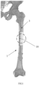
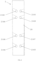
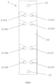
- Fig. 2 is a front view of one preferred structure of a bidirectional fixation steel plate 2 of the present invention.
- the fixation steel plate 2 comprises a steel plate body 20 which is preferably made of stainless steel by an integral molding process.
- the steel plate body 20 is used to be implanted from a front side of the bone shaft and has a structure matched with the front side of the bone shaft to fixedly fit with the fracture end, support and stabilize the fracture end, and promote fracture healing.
- the steel plate body 20 of the embodiment is preferably provided with four pairs of guide holes (for example, reference numerals 2101-2108, i.e.
- Each of the guide holes is provided with a specific angle, when performing locking and fixing using the first locking screws passing through along the angles of the guide holes, the specific angles directly enable the steel plate body 20 to be in close contact with the bone shaft and enable the first locking screws passing through to clamp the intramedullary nail together to control the rotation and axial stability of the intramedullary nail, that is to say, achieve a close fit between the steel plate body 20 and the front side of the bone shaft as well as fixation and anti-rotation of the intramedullary nail, and then achieve axial stability, fixed support and anti-rotation for the bone shaft fracture end.
- the guide hole 2101, the guide hole 2105, the guide hole 2107 and the guide hole 2103 are arranged in an approximate straight line
- the guide hole 2102, the guide hole 2106, the guide hole 2108 and the guide hole 2104 are arranged in an approximate straight line, that is, all the guide holes are arranged in four rows and double columns, and the arrangement shape may also be set in any other mode as long as it ensures the effects of effective fixation, anti-rotation, anti-axial instability and ensures minimum injury to patients during actual applications.
- the bidirectional fixation steel plate 2 proposed by the present invention adopts an integrally molded steel plate body 20 which is implanted from the front side of the bone shaft and has a structure matched with the front side of the bone shaft, and may achieve the good effect of fitting and fixing the fracture end.
- the steel plate body 20 may be matched with the first locking screws to achieve the axial positioning and fixation of the long bone shaft fracture area and prevent the dislocation of the fracture site, and may stabilize and support the fracture non-healing or nonunion site at the fracture end, which effectively ensures the stability fracture healing, further guarantees to assist in the accurate positioning, reduction and healing of the fracture site, accelerates and promotes fracture healing and makes the fracture healing state better.
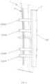
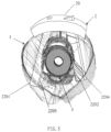
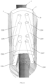
- Figs. 3 to 5 are structural schematic diagrams showing a preferred bidirectional fixation steel plate 2 proposed by the present invention in a used state.
- a bone cortex cutting operation is performed at the nonunion site using a sharp osteotome, to fully expose the nonunion site; bone paste operation and cortex bone jump are respectively performed using a minimally invasive bone extraction drill; bone paste is filled in the nonunion site, cancellous bone strip is paved under the cut bone cortex; stripping under periosteum is made using the extensibility of skin and muscle; then, the bidirectional fixation steel plate 2 shown in Fig.
- the first locking screw 2201 and the first locking screw 2202 respectively pass through the guide hole 2101 and the guide hole 2102 provided in the steel plate body 20 at a certain angle
- the first locking screw 2205 and the first locking screw 2206 respectively pass through the guide hole 2105 and the guide hole 2106 provided in the steel plate body 20 at a certain angle
- the first locking screw 2207 and the first locking screw 2208 respectively pass through the guide hole 2107 and the guide hole 2108 provided in the steel plate body 20 at a certain angle
- the first locking screw 2203 and the first locking screw 2204 respectively pass through the guide hole 2103 and the guide hole 2104 provided in the steel plate body 20 at a certain angle, to closely fit the steel plate body 20 with the front side of the bone shaft so as to fix the fracture end
- the steel plate body 20 cooperates with respective guide holes to make all locking screw passing through the guide holes to clamp the intramedullary nail 3 together to control the rotation and axial stability of the intramedullary nail 3, thereby achieving axial support, fixation, anti-rot
- each of the above certain angles may be reasonably set according to the actual situation as long as it ensures that each pair of first locking screws may effectively clamp the intramedullary nail 3, that is, achieves the effects of effective fixation, anti-rotation, anti-axial instability and ensure minimum injury to patients during actual applications.
- Fig. 5 is a top view of Fig. 4 , i.e.
- the above four pairs of first locking screws are arranged in two approximate straight lines, that is, arranged in four rows and double columns, and each of the first locking screws passing through the steel plate body 20 is closely fitted with the intramedullary nail 3 and is fixed through the cortex (i.e. between the cortex and the periosteum), to clamp the intramedullary nail 3 together so as to control the rotation and axial stability of the intramedullary nail 3, and strengthen the effects of axial support, anti-rotation and stability of the intramedullary nail 3.
- a negative pressure drainage tube is intubated, and periosteum, myofascial fascia, deep fascia, subcutaneous tissue and skin are closed by suture; and the drainage tube is pulled out 48 hours after the operation. Then, the patient with fracture takes daily exercises of passive extreme knee motion, lower limb isometric contraction, and weight-bearing activities under pain tolerance (toes on ground by 5 kg). The patient receives X-ray examination monthly to determine the weight-bearing process according to fracture healing condition until the patient fully recovers.
- Fig. 6 is a front view of another preferred structure of a bidirectional fixation steel plate of the present invention.
- positioning holes 23 for the second locking screw to pass through are provided at both the distal end and proximal end of the steel plate body 20 (that is to say, at an upper end portion and a lower end portion of the steel plate body), and the angles of the positioning holes enable the second locking screws passing through the positioning holes to position the steel plate body 20 in a position in close contact with the bone shaft, thus further improving the accurate positioning and fixation of the bone shaft fracture end, and enhancing the fracture healing effect.
- the present invention further relates to a bone shaft fixation system, comprising the above bidirectional fixation steel plate, and further comprises an intramedullary nail and several first locking screw, wherein the bidirectional fixation steel plate may adopt the bidirectional fixation steel plate as shown in Figs. 1 to 5 , the intramedullary nail is used to fix the fracture end and has a structure matched with an intramedullary cavity of the bone shaft, and each of the first locking screws passes through corresponding guide hole respectively and then is closely fitted with the side surface of the intramedullary nail and fixedly clamp the intramedullary nail together for controlling the rotation and axial stability of the intramedullary nail.
- the bone shaft fixation system may further comprise second locking screws passing through the positioning holes for positioning the bidirectional fixation steel plate.
- the bidirectional fixation steel plate adopts the structure as shown in Fig. 6 , that is, positioning holes for the second locking screws to pass through may also be provided at the distal end and/or proximal end of the steel plate body (that is, the upper end portion and/or the lower end portion of the steel plate body), and the angles of the positioning holes enable the second locking screws passing through to position the steel plate body in a position in close contact with the bone shaft, so as to achieve accurate positioning and fixation of the bone shaft fracture end, and enhancing the fracture healing effect.
- the locking screws (the first locking screws and the second locking screws) for fixing the bidirectional fixation steel plate may have a diameter ranging from 2.4 mm to 4.5 mm; and the locking screws for fixing the bidirectional fixation steel plate (the first locking screws and the second locking screws) may be hollow locking screws or solid locking screws.
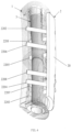
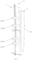
- Fig. 7 and Fig. 8 are structural schematic diagrams showing a preferred bone shaft fixation system of the present invention in a used state.
- Fig. 7 is side view
- Fig. 8 is a perspective view, in which the bidirectional fixation steel plate 2 and the intramedullary nail 3 shown in Fig. 3 or Fig. 4 are included.
- Fixation of the bidirectional fixation steel plate 2, and clamping and fixation of the intramedullary nail 3 are conducted by a plurality of first locking screws as shown in Figs. 3 to 4 in the above-mentioned mode, to control rotation and strengthen the support.
- the intramedullary nail 3 has a structure matched with an intramedullary cavity of the bone shaft, first locking screws respectively passing through respective pairs of guide holes are closely fitted with the side surface of the intramedullary nail and control the rotation and axial stability of the intramedullary nail 3, that is to say, all the first locking screws passing through the steel plate body 20 are closely fitted with the intramedullary nail 3 and are fixed through the cortex (that is, between the cortex and the periosteum), and clamp the intramedullary nail 3 together to control the rotation and axial stability of the intramedullary nail 3, thus an overall structure that all the first locking screws tangentially embrace the intramedullary nail 3 is formed, to further strengthen the effects of axial support, anti-rotation and stability of the intramedullary nail 3, and then achieve support, anti-rotation and axial stability of the bone shaft fracture end.
- the intramedullary nail 3 may be inserted into the intramedullary cavity of the bone shaft through the bone shaft fracture end, and the bidirectional fixation steel plate 2 may be implanted through a conventional anterolateral incision.
- the intraoperative injury surface, degree of injury and amount of bleeding are usually smaller, and postoperative healing and recovery speed are faster.
- the bidirectional fixation steel plate 2 and the intramedullary nail 3 cooperate with each other, the long axis of the steel plate body 20 of the bidirectional fixation steel plate 2 is consistent with the intramedullary nail 3, the intramedullary nail 3 achieves the effective support and fixation of the fracture end, each of the first locking screws passing through the bidirectional fixation steel plate 2 is closely fitted with the intramedullary nail 3 and is fixed through the cortex, that is, the steel plate body 20 achieves the effects of controlling rotation and strengthening support of the intramedullary nail 3 by the bidirectional fixing screws (or the bidirectional locking screws) through cooperation of respective guide holes provided with specific angles and respective first locking screws, and then achieves accurate positioning and fixation of the bone shaft fracture site as well as anti-rotation and anti-axial instability, further strengthens the effective support and stability for the bone shaft fracture, and assists in the accurate positioning and fixation of the fracture site, thereby effectively ensuring the stability after reduction of the bone shaft fracture.
Landscapes
- Health & Medical Sciences (AREA)
- Orthopedic Medicine & Surgery (AREA)
- Surgery (AREA)
- Life Sciences & Earth Sciences (AREA)
- Heart & Thoracic Surgery (AREA)
- Nuclear Medicine, Radiotherapy & Molecular Imaging (AREA)
- Engineering & Computer Science (AREA)
- Biomedical Technology (AREA)
- Neurology (AREA)
- Medical Informatics (AREA)
- Molecular Biology (AREA)
- Animal Behavior & Ethology (AREA)
- General Health & Medical Sciences (AREA)
- Public Health (AREA)
- Veterinary Medicine (AREA)
- Surgical Instruments (AREA)
Claims (9)
- Système de fixation de tige osseuse, comprenant une plaque d'angle de fixation bidirectionnelle (2) et un clou intramédullaire (3), la plaque d'angle de fixation bidirectionnelle comprenant un corps de plaque d'angle (20), dans lequel le corps de plaque d'angle est configuré pour être utilisé pour être implanté à partir d'un côté avant d'une tige osseuse (1) et présente une structure configurée, au côté avant de la tige osseuse, pour s'adapter de manière fixe à une extrémité de fracture, le corps de la plaque d'angle est pourvu d'au moins deux paires de trous de guidage (2101-2108) pour que les premières vis de verrouillage (2201-2208) passent respectivement dans la structure configurée pour s'adapter au côté avant de la tige osseuse (1), et
les trous de guidage (2101-2108) sont pourvus d'angles spécifiques qui permettent à toutes les premières vis de verrouillage passant par les trous de guidage de serrer le clou intramédullaire ensemble pour contrôler la rotation et la stabilité axiale du clou intramédullaire (3). - Système de fixation de la tige osseuse selon la revendication 1, dans lequel des trous de positionnement (23) pour le passage des secondes vis de verrouillage sont prévus à une extrémité distale et/ou une extrémité proximale du corps de plaque d'angle (20), et les angles des trous de positionnement (23) permettent aux secondes vis de verrouillage passant par les trous de positionnement de placer le corps de plaque d'angle (20) dans la position en contact étroit avec la tige osseuse (1).
- Système de fixation de la tige osseuse selon la revendication 2, dans lequel le corps de plaque d'angle (20) est fabriqué par un procédé de moulage intégral.
- Système de fixation de la tige osseuse selon l'une des revendications 1 à 3, dans lequel le corps de plaque d'angle (20) a un axe long cohérent avec le clou intramédullaire (3) lorsqu'il est implanté, et des paires respectives de trous de guidage sont disposées le long de l'axe long du corps de plaque d'angle, les trous de guidage étant disposés en doubles colonnes.
- Système de fixation de la tige osseuse selon la revendication 4, dans lequel le corps de plaque d'angle est pourvu de deux paires de trous de guidage (2101-2108) dans la structure correspondant au côté avant de la tige osseuse (1), chaque paire de trous de guidage (2101-2108) est disposée le long d'un axe court du corps de plaque d'angle (20), et les trous de guidage (2101-2108) sont divisés en deux rangées le long de l'axe long du corps de plaque d'angle (20).
- Système de fixation de la tige osseuse selon la revendication 4, dans lequel le corps de plaque d'angle (20) est pourvu de quatre paires de trous de guidage (2101-2108) dans la structure configurée pour s'adapter au côté avant de la tige osseuse (1), chaque paire de trous de guidage (2101-2108) sont disposés le long de l'axe court du corps de plaque d'angle (20), et les trous de guidage (2101-2108) sont divisés en quatre rangées le long de l'axe long du corps de plaque d'angle (20).
- Système de fixation de la tige osseuse selon l'une des revendications 1 à 6, dans lequel le système de fixation de la tige osseuse comprend en outre des secondes vis de verrouillage passant à travers les trous de positionnement (23) pour positionner la plaque d'angle de fixation bidirectionnelle (2).
- Système de fixation de la tige osseuse selon l'une des revendications 1 à 7, dans lequel chacune des premières vis de verrouillage (2201-2208) et des secondes vis de verrouillage a un diamètre compris entre 2,4 et 4,5 mm.
- Système de fixation de la tige osseuse selon l'une quelconque des revendications 1 à 7, dans lequel les premières vis de verrouillage (2201-2208) et/ou les secondes vis de verrouillage sont des vis de verrouillage creuses ou des vis de verrouillage pleines.
Applications Claiming Priority (1)
| Application Number | Priority Date | Filing Date | Title |
|---|---|---|---|
| PCT/CN2016/102738 WO2018072181A1 (fr) | 2016-10-20 | 2016-10-20 | Plaque d'angle pour fixation bidirectionnelle et système de fixation osseuse associé |
Publications (4)
| Publication Number | Publication Date |
|---|---|
| EP3530223A1 EP3530223A1 (fr) | 2019-08-28 |
| EP3530223A4 EP3530223A4 (fr) | 2019-11-06 |
| EP3530223C0 EP3530223C0 (fr) | 2024-05-22 |
| EP3530223B1 true EP3530223B1 (fr) | 2024-05-22 |
Family
ID=62019057
Family Applications (1)
| Application Number | Title | Priority Date | Filing Date |
|---|---|---|---|
| EP16919581.5A Active EP3530223B1 (fr) | 2016-10-20 | 2016-10-20 | Plaque d'angle pour fixation bidirectionnelle et système de fixation osseuse associé |
Country Status (5)
| Country | Link |
|---|---|
| US (1) | US20220378483A1 (fr) |
| EP (1) | EP3530223B1 (fr) |
| JP (1) | JP6751995B2 (fr) |
| ES (1) | ES2982366T3 (fr) |
| WO (1) | WO2018072181A1 (fr) |
Families Citing this family (3)
| Publication number | Priority date | Publication date | Assignee | Title |
|---|---|---|---|---|
| US12011199B2 (en) | 2020-10-15 | 2024-06-18 | DePuy Synthes Products, Inc. | Bone plate, bone plate system, and method of using the same |
| US11806029B2 (en) | 2021-01-06 | 2023-11-07 | DePuy Synthes Products, Inc. | Locking trocar and method of using the same |
| CN113413248A (zh) * | 2021-07-27 | 2021-09-21 | 上海交通大学医学院附属第九人民医院 | 一种能够保留髓内钉的合抱式假体 |
Citations (1)
| Publication number | Priority date | Publication date | Assignee | Title |
|---|---|---|---|---|
| WO2017035302A1 (fr) * | 2015-08-27 | 2017-03-02 | Globus Medical, Inc. | Système de stabilisation humérale proximale |
Family Cites Families (17)
| Publication number | Priority date | Publication date | Assignee | Title |
|---|---|---|---|---|
| US5356410A (en) * | 1991-12-13 | 1994-10-18 | Dietmar Pennig | Adjuvant for osteosynthesis in the case of pertrochanteric fracture of the neck of the femur |
| US5352228A (en) * | 1993-05-10 | 1994-10-04 | Kummer Frederick J | Apparatus and method to provide compression for a locked intramedullary nail |
| AU6268798A (en) * | 1997-02-11 | 1998-08-26 | Gary Karlin Michelson | Anterior cervical plating system, instrumentation, and method of installation |
| US6179839B1 (en) * | 1999-09-20 | 2001-01-30 | Kinetikos Medical Incorporated | Bone fusion apparatus and method |
| US20030069581A1 (en) * | 2001-10-04 | 2003-04-10 | Stinson David T. | Universal intramedullary nails, systems and methods of use thereof |
| EP1398001B1 (fr) * | 2002-09-03 | 2008-08-06 | Dietmar Prof. Dr. Pennig | Système de fixation pour fractures d'os |
| US8236034B2 (en) * | 2004-04-19 | 2012-08-07 | Globus Medical, Inc. | Bone fixation plate |
| US8382807B2 (en) * | 2005-07-25 | 2013-02-26 | Smith & Nephew, Inc. | Systems and methods for using polyaxial plates |
| BRPI0815259A2 (pt) * | 2007-08-27 | 2015-09-01 | Sushrut Surgicals Pvt Ltd | Placas ósseas e montagens de placas ósseas |
| EP2207503B1 (fr) * | 2007-09-27 | 2014-04-23 | Synthes GmbH | Combinaison clou-plaque |
| US20090177240A1 (en) * | 2007-10-16 | 2009-07-09 | Perez Edward A | Long bone fixation system and methods |
| AT507086B1 (de) * | 2008-09-16 | 2010-02-15 | Haininger Christian Dr | Implantat, insbesondere marknagel für die behandlung einer proximalen humerusfraktur |
| WO2010124205A1 (fr) * | 2009-04-24 | 2010-10-28 | Synthes Usa, Llc | Vis multiplexées |
| CN103491889B (zh) * | 2011-04-01 | 2016-10-12 | 新特斯有限责任公司 | 脊椎后路板固定系统 |
| CN102949228B (zh) * | 2011-08-19 | 2015-11-18 | 上海市第六人民医院 | 一种骨折内固定器 |
| US9089375B2 (en) * | 2013-10-12 | 2015-07-28 | Interfix, Llc | Combined intramedullary and extramedullary surgical aiming system and method |
| CN104771221B (zh) * | 2015-04-22 | 2017-10-17 | 熊静 | 一种用于插入靶骨的髓内钉及其专用导向系统 |
-
2016
- 2016-10-20 ES ES16919581T patent/ES2982366T3/es active Active
- 2016-10-20 JP JP2019521407A patent/JP6751995B2/ja active Active
- 2016-10-20 US US16/343,531 patent/US20220378483A1/en not_active Abandoned
- 2016-10-20 WO PCT/CN2016/102738 patent/WO2018072181A1/fr not_active Ceased
- 2016-10-20 EP EP16919581.5A patent/EP3530223B1/fr active Active
Patent Citations (1)
| Publication number | Priority date | Publication date | Assignee | Title |
|---|---|---|---|---|
| WO2017035302A1 (fr) * | 2015-08-27 | 2017-03-02 | Globus Medical, Inc. | Système de stabilisation humérale proximale |
Also Published As
| Publication number | Publication date |
|---|---|
| ES2982366T3 (es) | 2024-10-15 |
| EP3530223A1 (fr) | 2019-08-28 |
| US20220378483A1 (en) | 2022-12-01 |
| JP2019533511A (ja) | 2019-11-21 |
| EP3530223A4 (fr) | 2019-11-06 |
| EP3530223C0 (fr) | 2024-05-22 |
| JP6751995B2 (ja) | 2020-09-09 |
| WO2018072181A1 (fr) | 2018-04-26 |
Similar Documents
| Publication | Publication Date | Title |
|---|---|---|
| JP6786646B2 (ja) | 大腿骨頸部骨折用インプラント | |
| AU2002329787B2 (en) | Method and apparatus for percutaneously securing a bone screw and a bone plate to a bone of a patient | |
| US20030135211A1 (en) | Intramedullary nail, device for inserting a screw into the same and method thereof | |
| US20230397918A1 (en) | System for Connecting a Connecting Device, in Particular a Distractor, to a Bone | |
| US11583328B2 (en) | Femoral nail and instrumentation system | |
| US10076375B1 (en) | Implantable device facilitating rotational-guided growth and method of use | |
| EP3530223B1 (fr) | Plaque d'angle pour fixation bidirectionnelle et système de fixation osseuse associé | |
| EP3530222B1 (fr) | Plaque d'angle pour protection de type ailette et système de fixation osseuse associé | |
| EP0517435A1 (fr) | Dispositif intramédullaire pour l'ostéosynthèse | |
| CN207400790U (zh) | 一种双向固定钢板以及骨干固定系统 | |
| CN106344141B (zh) | 一种双向固定钢板以及骨干固定系统 | |
| US12496104B1 (en) | Intramedullary bone fixation devices, systems, and methods | |
| CN207400789U (zh) | 一种护翼型角钢板以及骨干固定系统 | |
| US12491013B2 (en) | Orthopaedic implant and system | |
| CN106236238B (zh) | 一种护翼型角钢板以及骨干固定系统 | |
| US20250275798A1 (en) | Femoral Neck Fracture Fixation Device | |
| Weber et al. | 11.2 Openreductionandinternalfixationofthefemur: plating |
Legal Events
| Date | Code | Title | Description |
|---|---|---|---|
| STAA | Information on the status of an ep patent application or granted ep patent |
Free format text: STATUS: THE INTERNATIONAL PUBLICATION HAS BEEN MADE |
|
| PUAI | Public reference made under article 153(3) epc to a published international application that has entered the european phase |
Free format text: ORIGINAL CODE: 0009012 |
|
| STAA | Information on the status of an ep patent application or granted ep patent |
Free format text: STATUS: REQUEST FOR EXAMINATION WAS MADE |
|
| 17P | Request for examination filed |
Effective date: 20190517 |
|
| AK | Designated contracting states |
Kind code of ref document: A1 Designated state(s): AL AT BE BG CH CY CZ DE DK EE ES FI FR GB GR HR HU IE IS IT LI LT LU LV MC MK MT NL NO PL PT RO RS SE SI SK SM TR |
|
| AX | Request for extension of the european patent |
Extension state: BA ME |
|
| A4 | Supplementary search report drawn up and despatched |
Effective date: 20191008 |
|
| RIC1 | Information provided on ipc code assigned before grant |
Ipc: A61B 17/56 20060101ALI20191001BHEP Ipc: A61B 17/72 20060101ALN20191001BHEP Ipc: A61B 17/58 20060101AFI20191001BHEP Ipc: A61B 17/80 20060101ALN20191001BHEP |
|
| RAP1 | Party data changed (applicant data changed or rights of an application transferred) |
Owner name: TIANJIN ZHENGTIAN MEDICAL INSTRUMENT CO., LTD. Owner name: CHEN, HUA Owner name: TANG, PEIFU |
|
| RIN1 | Information on inventor provided before grant (corrected) |
Inventor name: TANG, PEIFU Inventor name: TIANJIN ZHENGTIAN MEDICAL INSTRUMENT CO., LTD. Inventor name: CHEN, HUA |
|
| DAV | Request for validation of the european patent (deleted) | ||
| DAX | Request for extension of the european patent (deleted) | ||
| GRAP | Despatch of communication of intention to grant a patent |
Free format text: ORIGINAL CODE: EPIDOSNIGR1 |
|
| STAA | Information on the status of an ep patent application or granted ep patent |
Free format text: STATUS: GRANT OF PATENT IS INTENDED |
|
| INTG | Intention to grant announced |
Effective date: 20231218 |
|
| GRAS | Grant fee paid |
Free format text: ORIGINAL CODE: EPIDOSNIGR3 |
|
| GRAA | (expected) grant |
Free format text: ORIGINAL CODE: 0009210 |
|
| STAA | Information on the status of an ep patent application or granted ep patent |
Free format text: STATUS: THE PATENT HAS BEEN GRANTED |
|
| AK | Designated contracting states |
Kind code of ref document: B1 Designated state(s): AL AT BE BG CH CY CZ DE DK EE ES FI FR GB GR HR HU IE IS IT LI LT LU LV MC MK MT NL NO PL PT RO RS SE SI SK SM TR |
|
| REG | Reference to a national code |
Ref country code: GB Ref legal event code: FG4D |
|
| RIN1 | Information on inventor provided before grant (corrected) |
Inventor name: TANG, PEIFU Inventor name: CHEN, HUA |
|
| REG | Reference to a national code |
Ref country code: CH Ref legal event code: EP |
|
| REG | Reference to a national code |
Ref country code: DE Ref legal event code: R096 Ref document number: 602016087679 Country of ref document: DE |
|
| REG | Reference to a national code |
Ref country code: IE Ref legal event code: FG4D |
|
| U01 | Request for unitary effect filed |
Effective date: 20240607 |
|
| U07 | Unitary effect registered |
Designated state(s): AT BE BG DE DK EE FI FR IT LT LU LV MT NL PT SE SI Effective date: 20240620 |
|
| PG25 | Lapsed in a contracting state [announced via postgrant information from national office to epo] |
Ref country code: IS Free format text: LAPSE BECAUSE OF FAILURE TO SUBMIT A TRANSLATION OF THE DESCRIPTION OR TO PAY THE FEE WITHIN THE PRESCRIBED TIME-LIMIT Effective date: 20240922 |
|
| PG25 | Lapsed in a contracting state [announced via postgrant information from national office to epo] |
Ref country code: HR Free format text: LAPSE BECAUSE OF FAILURE TO SUBMIT A TRANSLATION OF THE DESCRIPTION OR TO PAY THE FEE WITHIN THE PRESCRIBED TIME-LIMIT Effective date: 20240522 |
|
| PG25 | Lapsed in a contracting state [announced via postgrant information from national office to epo] |
Ref country code: GR Free format text: LAPSE BECAUSE OF FAILURE TO SUBMIT A TRANSLATION OF THE DESCRIPTION OR TO PAY THE FEE WITHIN THE PRESCRIBED TIME-LIMIT Effective date: 20240823 |
|
| REG | Reference to a national code |
Ref country code: ES Ref legal event code: FG2A Ref document number: 2982366 Country of ref document: ES Kind code of ref document: T3 Effective date: 20241015 |
|
| PG25 | Lapsed in a contracting state [announced via postgrant information from national office to epo] |
Ref country code: PL Free format text: LAPSE BECAUSE OF FAILURE TO SUBMIT A TRANSLATION OF THE DESCRIPTION OR TO PAY THE FEE WITHIN THE PRESCRIBED TIME-LIMIT Effective date: 20240522 |
|
| PG25 | Lapsed in a contracting state [announced via postgrant information from national office to epo] |
Ref country code: PL Free format text: LAPSE BECAUSE OF FAILURE TO SUBMIT A TRANSLATION OF THE DESCRIPTION OR TO PAY THE FEE WITHIN THE PRESCRIBED TIME-LIMIT Effective date: 20240522 Ref country code: NO Free format text: LAPSE BECAUSE OF FAILURE TO SUBMIT A TRANSLATION OF THE DESCRIPTION OR TO PAY THE FEE WITHIN THE PRESCRIBED TIME-LIMIT Effective date: 20240822 Ref country code: IS Free format text: LAPSE BECAUSE OF FAILURE TO SUBMIT A TRANSLATION OF THE DESCRIPTION OR TO PAY THE FEE WITHIN THE PRESCRIBED TIME-LIMIT Effective date: 20240922 Ref country code: HR Free format text: LAPSE BECAUSE OF FAILURE TO SUBMIT A TRANSLATION OF THE DESCRIPTION OR TO PAY THE FEE WITHIN THE PRESCRIBED TIME-LIMIT Effective date: 20240522 Ref country code: GR Free format text: LAPSE BECAUSE OF FAILURE TO SUBMIT A TRANSLATION OF THE DESCRIPTION OR TO PAY THE FEE WITHIN THE PRESCRIBED TIME-LIMIT Effective date: 20240823 Ref country code: RS Free format text: LAPSE BECAUSE OF FAILURE TO SUBMIT A TRANSLATION OF THE DESCRIPTION OR TO PAY THE FEE WITHIN THE PRESCRIBED TIME-LIMIT Effective date: 20240822 |
|
| U20 | Renewal fee for the european patent with unitary effect paid |
Year of fee payment: 9 Effective date: 20241023 |
|
| PG25 | Lapsed in a contracting state [announced via postgrant information from national office to epo] |
Ref country code: CZ Free format text: LAPSE BECAUSE OF FAILURE TO SUBMIT A TRANSLATION OF THE DESCRIPTION OR TO PAY THE FEE WITHIN THE PRESCRIBED TIME-LIMIT Effective date: 20240522 |
|
| PG25 | Lapsed in a contracting state [announced via postgrant information from national office to epo] |
Ref country code: RO Free format text: LAPSE BECAUSE OF FAILURE TO SUBMIT A TRANSLATION OF THE DESCRIPTION OR TO PAY THE FEE WITHIN THE PRESCRIBED TIME-LIMIT Effective date: 20240522 Ref country code: SK Free format text: LAPSE BECAUSE OF FAILURE TO SUBMIT A TRANSLATION OF THE DESCRIPTION OR TO PAY THE FEE WITHIN THE PRESCRIBED TIME-LIMIT Effective date: 20240522 |
|
| PG25 | Lapsed in a contracting state [announced via postgrant information from national office to epo] |
Ref country code: SM Free format text: LAPSE BECAUSE OF FAILURE TO SUBMIT A TRANSLATION OF THE DESCRIPTION OR TO PAY THE FEE WITHIN THE PRESCRIBED TIME-LIMIT Effective date: 20240522 |
|
| PG25 | Lapsed in a contracting state [announced via postgrant information from national office to epo] |
Ref country code: SM Free format text: LAPSE BECAUSE OF FAILURE TO SUBMIT A TRANSLATION OF THE DESCRIPTION OR TO PAY THE FEE WITHIN THE PRESCRIBED TIME-LIMIT Effective date: 20240522 Ref country code: SK Free format text: LAPSE BECAUSE OF FAILURE TO SUBMIT A TRANSLATION OF THE DESCRIPTION OR TO PAY THE FEE WITHIN THE PRESCRIBED TIME-LIMIT Effective date: 20240522 Ref country code: RO Free format text: LAPSE BECAUSE OF FAILURE TO SUBMIT A TRANSLATION OF THE DESCRIPTION OR TO PAY THE FEE WITHIN THE PRESCRIBED TIME-LIMIT Effective date: 20240522 Ref country code: CZ Free format text: LAPSE BECAUSE OF FAILURE TO SUBMIT A TRANSLATION OF THE DESCRIPTION OR TO PAY THE FEE WITHIN THE PRESCRIBED TIME-LIMIT Effective date: 20240522 |
|
| REG | Reference to a national code |
Ref country code: DE Ref legal event code: R097 Ref document number: 602016087679 Country of ref document: DE |
|
| PLBE | No opposition filed within time limit |
Free format text: ORIGINAL CODE: 0009261 |
|
| STAA | Information on the status of an ep patent application or granted ep patent |
Free format text: STATUS: NO OPPOSITION FILED WITHIN TIME LIMIT |
|
| 26N | No opposition filed |
Effective date: 20250225 |
|
| PG25 | Lapsed in a contracting state [announced via postgrant information from national office to epo] |
Ref country code: MC Free format text: LAPSE BECAUSE OF FAILURE TO SUBMIT A TRANSLATION OF THE DESCRIPTION OR TO PAY THE FEE WITHIN THE PRESCRIBED TIME-LIMIT Effective date: 20240522 |
|
| PG25 | Lapsed in a contracting state [announced via postgrant information from national office to epo] |
Ref country code: IE Free format text: LAPSE BECAUSE OF NON-PAYMENT OF DUE FEES Effective date: 20241020 |
|
| REG | Reference to a national code |
Ref country code: CH Ref legal event code: U11 Free format text: ST27 STATUS EVENT CODE: U-0-0-U10-U11 (AS PROVIDED BY THE NATIONAL OFFICE) Effective date: 20251101 |
|
| U20 | Renewal fee for the european patent with unitary effect paid |
Year of fee payment: 10 Effective date: 20251028 |
|
| PGFP | Annual fee paid to national office [announced via postgrant information from national office to epo] |
Ref country code: GB Payment date: 20251030 Year of fee payment: 10 |
|
| PGFP | Annual fee paid to national office [announced via postgrant information from national office to epo] |
Ref country code: CH Payment date: 20251101 Year of fee payment: 10 |
|
| PG25 | Lapsed in a contracting state [announced via postgrant information from national office to epo] |
Ref country code: CY Free format text: LAPSE BECAUSE OF FAILURE TO SUBMIT A TRANSLATION OF THE DESCRIPTION OR TO PAY THE FEE WITHIN THE PRESCRIBED TIME-LIMIT; INVALID AB INITIO Effective date: 20161020 |
|
| PGFP | Annual fee paid to national office [announced via postgrant information from national office to epo] |
Ref country code: ES Payment date: 20251103 Year of fee payment: 10 |
|
| PG25 | Lapsed in a contracting state [announced via postgrant information from national office to epo] |
Ref country code: HU Free format text: LAPSE BECAUSE OF FAILURE TO SUBMIT A TRANSLATION OF THE DESCRIPTION OR TO PAY THE FEE WITHIN THE PRESCRIBED TIME-LIMIT; INVALID AB INITIO Effective date: 20161020 |