EP3530248B1 - Rollstuhl - Google Patents
Rollstuhl Download PDFInfo
- Publication number
- EP3530248B1 EP3530248B1 EP19158018.2A EP19158018A EP3530248B1 EP 3530248 B1 EP3530248 B1 EP 3530248B1 EP 19158018 A EP19158018 A EP 19158018A EP 3530248 B1 EP3530248 B1 EP 3530248B1
- Authority
- EP
- European Patent Office
- Prior art keywords
- wheelchair
- tyre pressure
- control system
- pressure control
- tire pressure
- Prior art date
- Legal status (The legal status is an assumption and is not a legal conclusion. Google has not performed a legal analysis and makes no representation as to the accuracy of the status listed.)
- Active
Links
Images

Classifications
-
- A—HUMAN NECESSITIES
- A61—MEDICAL OR VETERINARY SCIENCE; HYGIENE
- A61G—TRANSPORT, PERSONAL CONVEYANCES, OR ACCOMMODATION SPECIALLY ADAPTED FOR PATIENTS OR DISABLED PERSONS; OPERATING TABLES OR CHAIRS; CHAIRS FOR DENTISTRY; FUNERAL DEVICES
- A61G5/00—Chairs or personal conveyances specially adapted for patients or disabled persons, e.g. wheelchairs
- A61G5/10—Parts, details or accessories
-
- B—PERFORMING OPERATIONS; TRANSPORTING
- B60—VEHICLES IN GENERAL
- B60C—VEHICLE TYRES; TYRE INFLATION; TYRE CHANGING; CONNECTING VALVES TO INFLATABLE ELASTIC BODIES IN GENERAL; DEVICES OR ARRANGEMENTS RELATED TO TYRES
- B60C23/00—Devices for measuring, signalling, controlling, or distributing tyre pressure or temperature, specially adapted for mounting on vehicles; Arrangement of tyre inflating devices on vehicles, e.g. of pumps or of tanks; Tyre cooling arrangements
- B60C23/02—Signalling devices actuated by tyre pressure
- B60C23/04—Signalling devices actuated by tyre pressure mounted on the wheel or tyre
- B60C23/0408—Signalling devices actuated by tyre pressure mounted on the wheel or tyre transmitting the signals by non-mechanical means from the wheel or tyre to a vehicle body mounted receiver
- B60C23/0479—Communicating with external units being not part of the vehicle, e.g. tools for diagnostic, mobile phones, electronic keys or service stations
-
- B—PERFORMING OPERATIONS; TRANSPORTING
- B60—VEHICLES IN GENERAL
- B60C—VEHICLE TYRES; TYRE INFLATION; TYRE CHANGING; CONNECTING VALVES TO INFLATABLE ELASTIC BODIES IN GENERAL; DEVICES OR ARRANGEMENTS RELATED TO TYRES
- B60C23/00—Devices for measuring, signalling, controlling, or distributing tyre pressure or temperature, specially adapted for mounting on vehicles; Arrangement of tyre inflating devices on vehicles, e.g. of pumps or of tanks; Tyre cooling arrangements
- B60C23/02—Signalling devices actuated by tyre pressure
- B60C23/04—Signalling devices actuated by tyre pressure mounted on the wheel or tyre
- B60C23/0491—Constructional details of means for attaching the control device
- B60C23/0496—Valve stem attachments positioned outside of the tyre chamber
-
- A—HUMAN NECESSITIES
- A61—MEDICAL OR VETERINARY SCIENCE; HYGIENE
- A61G—TRANSPORT, PERSONAL CONVEYANCES, OR ACCOMMODATION SPECIALLY ADAPTED FOR PATIENTS OR DISABLED PERSONS; OPERATING TABLES OR CHAIRS; CHAIRS FOR DENTISTRY; FUNERAL DEVICES
- A61G2203/00—General characteristics of devices
- A61G2203/30—General characteristics of devices characterised by sensor means
- A61G2203/34—General characteristics of devices characterised by sensor means for pressure
Definitions
- the invention relates to a wheelchair of the type mentioned in the preamble of claim 1.
- Such wheelchairs are well known. They have a frame and wheels which are arranged on the frame and have tires filled with a tire pressure.
- corresponding wheelchairs can be designed as manually operated wheelchairs or as electric wheelchairs.
- JP 2006 062414 A a wheelchair with the features of the preamble of claim 1 is known.
- Tire pressure monitoring systems are also through US 2017/251972 A1 , WO 2016/072831 A1 and WO 2016/198970 A1 known.
- the invention is based on the object of specifying a wheelchair of the type mentioned in the preamble of claim 1, the operational safety of which is improved.
- the invention is based on the knowledge that the operational safety of a wheelchair also depends on the tires being filled with a suitable tire pressure. Starting from this, the invention is based on the idea of operational safety of the wheelchair by automatically checking the tire pressure. For this purpose, the invention provides that the wheelchair has a tire pressure control system.
- the tire pressure control system provided according to the invention can be designed in a variety of ways, depending on the respective requirements.
- An advantageous further development of the invention provides that the tire pressure control system has sensor modules assigned to the tires which are in signal transmission connection with a central unit for transmitting signals representing the respective tire pressure.
- Corresponding tire pressure monitoring systems are available as relatively simple and inexpensive standard assemblies and are highly reliable.
- a wheelchair according to the invention with a tire pressure control system is only slightly more expensive to manufacture than a conventional wheelchair without a tire pressure control system while at the same time improving operational safety and comfort.
- the tire pressure control system has a display device or is connected to a display device for displaying tire pressure-related data. Using the displayed tire pressure-related data, a user of the wheelchair can, if necessary, find out what tire pressure is is present in the tires. If necessary, the user of the wheelchair can then adjust the tire pressure or have it adjusted.
- the tire pressure control system has a signal generating device or is in data transmission connection with a signal generating device which is designed and programmed in such a way that a warning signal is generated when a set or adjustable limit value of the tire pressure is reached.
- the warning signal can be an acoustic or visual signal which indicates to a user of the wheelchair that the tire pressure is not in the predetermined range.
- the central unit of the tire pressure monitoring system and the display device and the signal generating device can be provided as hardware assemblies on the wheelchair.
- An extremely advantageous development of the invention provides that the display device and / or the signal generating device are or is formed by a mobile telecommunication terminal that is in data transmission connection with the central unit of the tire pressure monitoring system.
- the hardware of a telecommunication terminal for example a smartphone, carried by a user of the wheelchair anyway can be used to carry out the corresponding functions of the tire pressure monitoring system.
- the implementation of a corresponding tire pressure control system on a wheelchair is further simplified. Operation is also simplified in that the user receives displays or signals from the tire pressure monitoring system, for example via his smartphone.
- At least one sensor module of the tire pressure control system can be screwed onto a valve of a tire.
- At least one sensor module has a wireless signal transmission connection with the central unit of the tire pressure control system.
- the wheelchair according to the invention is designed as an electric wheelchair:
- FIGS. 1 to 3 an embodiment of a wheelchair according to the invention in the form of an electric wheelchair is explained in more detail below.
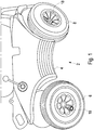
- Fig. 1 a perspective view of part of a wheelchair 2 according to the invention is shown in the form of an electric wheelchair which has a base body 4 designed as a chassis, on which wheels with tires 6, 8, 10, 12 are arranged, of which in Fig. 1 only three tires 6, 8, 10 can be seen.
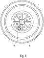
- the wheelchair 2 has a tire pressure monitoring system 14 (cf. Fig. 2 ), which has sensor modules 16, 18, 20, 22 assigned to tires 6, 8, 10, 12, which are each screwed onto a valve of the assigned tire 6, 8, 10, 12 (cf. Fig. 1 with respect to the tires 6, 8 and the sensor modules 16, 18 as well Fig. 3 with respect to the tire 6 and the sensor module 16).
- a tire pressure monitoring system 14 cf. Fig. 2
- sensor modules 16, 18, 20, 22 assigned to tires 6, 8, 10, 12 which are each screwed onto a valve of the assigned tire 6, 8, 10, 12 (cf. Fig. 1 with respect to the tires 6, 8 and the sensor modules 16, 18 as well Fig. 3 with respect to the tire 6 and the sensor module 16).
- the sensor modules 16, 18, 20, 22 are wirelessly, namely by radio, with a central unit 24 of the tire pressure control system 14 in data transmission connection and continuously transmit data representing the tire pressure of the respective tire 6 or 8 or 10 or 12 to the central unit 24.
- the tire pressure can be displayed permanently or at the request of the user of the wheelchair 2 on a display device 26.
- a signal generating device 28 can be used to generate a signal which indicates to the user of the wheelchair 2 that the tire pressure of one or more tires 6, 8, 10, 12 is outside the predetermined range, so that the user adjust the tire pressure of the tire or tires in question or have it adjusted.
- the display device 26 and / or the signal generating device 28 can or can be formed by a telecommunication terminal carried by the user of the wheelchair 2, for example a smartphone, which is in data transmission connection for example via radio with the central unit 24 of the tire pressure monitoring system 14. It is also possible that the central unit 24 of the tire pressure control system 14 is formed by the hardware of the telecommunication terminal with which the sensor modules 16, 18, 20, 22 are in data transmission connection.
- the tire pressure monitoring system 14 is in a signal transmission connection with a control device 30 for controlling a travel drive 32 of the wheelchair 2 (cf. Fig. 2 ) that the travel drive 32 can be or is being controlled as a function of output signals from the tire pressure control system 14.
- the travel drive can be an electromotive drive of an electric wheelchair or also an electromotive auxiliary drive of a manually driven wheelchair, for example a push rim wheelchair.
- the tire pressure monitoring system 14 can for example and in particular interact with the control device 30 of the travel drive 32 in such a way that the drive power of the travel drive 32 is influenced as a function of the tire pressure determined in each case, for example in such a way that when the tire pressure falls below a set or adjustable tire pressure, the drive power and so that the maximum speed of the wheelchair is limited. In this way, the operational safety of the wheelchair is significantly increased.
- the travel drive 32 is an electromotive auxiliary drive of a manually driven wheelchair, for example a push rim wheelchair, in which a drive unit of the auxiliary drive is assigned to each drive wheel of the wheelchair
- the tire pressure monitoring system can interact with the control device 30 in such a way that, depending on the the tire pressure determined by the tire pressure control system, the drive units are controlled differently from one another.
- the drive units of the auxiliary drive can be operated independently by the control device depending on the output signals of the tire pressure monitoring system are controlled from each other in such a way that the deviation from driving straight ahead is compensated and the wheelchair drives straight ahead in the manner specified by the user.
Landscapes
- Engineering & Computer Science (AREA)
- Mechanical Engineering (AREA)
- Health & Medical Sciences (AREA)
- Life Sciences & Earth Sciences (AREA)
- Animal Behavior & Ethology (AREA)
- General Health & Medical Sciences (AREA)
- Public Health (AREA)
- Veterinary Medicine (AREA)
- Measuring Fluid Pressure (AREA)
Description
- Die Erfindung betrifft einen Rollstuhl der im Oberbegriff des Anspruchs 1 genannten Art.
- Derartige Rollstühle sind allgemein bekannt. Sie weisen einen Rahmen und an dem Rahmen angeordnete Räder auf, die mit einem Reifendruck befüllte Reifen aufweisen.
- Entsprechend den jeweiligen Anforderungen können entsprechende Rollstühle als manuell betriebene Rollstühle oder als Elektro-Rollstühle ausgebildet sein.
- Durch
JP 2006 062414 A - Reifendruckkontrollsysteme sind auch durch
US 2017/251972 A1 ,WO 2016/072831 A1 undWO 2016/198970 A1 bekannt. - Der Erfindung liegt die Aufgabe zu Grunde, einen Rollstuhl der im Oberbegriff des Anspruchs 1 genannten Art anzugeben, dessen Betriebssicherheit verbessert ist.
- Diese Aufgabe wird durch die im Anspruch 1 angegebene Erfindung gelöst.
- Die Erfindung geht von der Erkenntnis aus, dass auch bei einem Rollstuhl die Betriebsicherheit davon abhängt, dass die Reifen mit einem passenden Reifendruck befüllt sind. Der Erfindung liegt hiervon ausgehend der Gedanke zu Grunde, die Betriebssicherheit des Rollstuhls dadurch zu verbessern, dass der Reifendruck automatisch kontrolliert wird. Zu diesem Zweck sieht die Erfindung vor, dass der Rollstuhl ein Reifendrucckontrollsystem aufweist.
- Auf diese Weise kann während des Betriebs des Rollstuhls ständig geprüft bzw. überwacht werden, dass die Reifen des Rollstuhls mit einem passenden Reifendruck befüllt sind. Dadurch sind Betriebstörungen, die von einem zu geringen Reifendruck herrühren, ebenso vermieden wie Komforteinbußen, die von einem zu hohen Reifendruck herrühren.
- Auf diese Weise sind sowohl die Betriebssicherheit des Rollstuhls als auch der Komfort für den Benutzer des Rollstuhls verbessert.
- Entsprechend den jeweiligen Anforderungen kann das erfindungsgemäß vorgesehene Reifendruckkontrollsystem in vielfältiger Weise ausgestaltet sein. Eine vorteilhafte Weiterbildung der Erfindung sieht insoweit vor, dass das Reifendruckkontrollsystem den Reifen zugeordnete Sensormodule aufweist, die mit einer Zentraleinheit in Signalübertragungsverbindung stehen zum Übertragen von den jeweiligen Reifendruck repräsentierenden Signalen. Entsprechende Reifendruckkontrollsysteme stehen als relativ einfache und kostengünstige Standardbaugruppen zur Verfügung und weisen eine hohe Zuverlässigkeit auf. Ein erfindungsgemäßer Rollstuhl mit Reifendruckkontrollsystem ist nur geringfügig teurer in der Herstellung als ein herkömmlicher Rollstuhl ohne Reifendruckkontrollsystem bei gleichzeitig verbesserter Betriebssicherheit und verbessertem Komfort.
- Eine andere vorteilhafte Weiterbildung der Erfindung sieht vor, dass das Reifendruckkontrollsystem eine Anzeigeeinrichtung aufweist oder mit einer Anzeigeeinrichtung verbunden ist zur Anzeige von reifendruckbezogenen Daten. Anhand der angezeigten reifendruckbezogenen Daten kann sich ein Benutzer des Rollstuhls bei Bedarf darüber informieren, welcher Reifendruck in den Reifen vorliegt. Bei Bedarf kann der Benutzer des Rollstuhls dann den Reifendruck ggf. anpassen oder anpassen lassen.
- Eine andere vorteilhafte Weiterbildung der Erfindung sieht vor, dass das Reifendruckkontrollsystem eine Signalerzeugungseinrichtung aufweist oder mit einer Signalerzeugungseinrichtung in Datenübertragungsverbindung steht, die derart ausgebildet und programmiert ist, dass beim Erreichen eines eingestellten oder einstellbaren Grenzwertes des Reifendrucks ein Warnsignal erzeugt wird. Bei dem Warnsignal kann es sich um ein akustisches oder optisches Signal handeln, das einem Benutzer des Rollstuhls angezeigt, dass sich der Reifendruck nicht in dem vorbestimmten Bereich befindet.
- Die Zentraleinheit des Reifendruckkontrollsystems sowie die Anzeigeeinrichtung und die Signalerzeugungseinrichtung können als Hardware-Baugruppen an dem Rollstuhl vorgesehen sein. Eine außerordentlich vorteilhafte Weiterbildung der Erfindung sieht insoweit vor, dass die Anzeigeeinrichtung und/oder die Signalerzeugungseinrichtung durch ein mobiles Telekommunikationsendgerät gebildet sind bzw. ist, dass mit der Zentraleinheit des Reifendruckkontrollsystems in Datenübertragungsverbindung steht. Auf diese Weise kann die Hardware eines von einem Benutzer des Rollstuhls ohnehin mitgeführten Telekommunikationsendgeräts, beispielsweise eines Smartphones, verwendet werden, um die entsprechenden Funktionen des Reifendruckkontrollsystems auszuführen. Auf diese Weise ist die Implementierung eines entsprechenden Reifendruckkontrollsystems an einem Rollstuhl weiter vereinfacht. Außerdem ist auch die Bedienung vereinfacht, indem der Benutzer Anzeigen oder Signale des Reifendruckkontrollsystems beispielsweise über sein Smartphone erhält.
- Eine andere vorteilhafte Weiterbildung der Erfindung sieht vor, dass wenigstens ein Sensormodul des Reifendruckkontrollsystems auf ein Ventil eines Reifens aufschraubbar ist.
- Eine vorteilhafte Weiterbildung der vorgenannten Ausführungsform sieht vor, dass wenigstens ein Sensormodul drahtlos mit der Zentraleinheit des Reifendruckkontrollsystems in Signalübertragungsverbindung steht.
- Der erfindungsgemäße Rollstuhl ist als Elektro-Rollstuhl ausgebildet :
- Die Erfindung wird nachfolgend anhand eines Ausführungsbeispiels unter Bezugnahme auf die beigefügte schematisierte Zeichnung näher erläutert.
- Es zeigt:
- Fig. 1
- eine Perspektivansicht eines Teiles eines erfindungsgemäßen Rollstuhles im Bereich der Reifen,
- Fig. 2
- ein stark schematisiertes Blockschaltbild eines erfindungsgemäßen Rollstuhles und
- Fig. 3
- in gleicher Darstellung wie
Fig. 1 , jedoch in gegenüberFig. 1 vergrößertem Maßstab einen Reifen des Rollstuhls gemäßFig. 1 . - Unter Bezugnahme auf
Fig. 1 bis Fig. 3 wird nachfolgend ein Ausführungsbeispiel eines erfindungsgemäßen Rollstuhles in Form eines Elektro-Rollstuhles näher erläutert. - In
Fig. 1 ist in einer Perspektivansicht ein Teil eines erfindungsgemäßen Rollstuhles 2 in Form eines Elektro-Rollstuhles dargestellt, der einen als Fahrgestell ausgebildeten Grundkörper 4 aufweist, an dem Räder mit Reifen 6, 8, 10, 12 angeordnet sind, von denen inFig. 1 lediglich drei Reifen 6, 8, 10 erkennbar sind. - Erfindungsgemäß weist der Rollstuhl 2 ein Reifendruckkontrollsystem 14 auf (vgl.
Fig. 2 ), das den Reifen 6, 8, 10, 12 zugeordnete Sensormodule 16, 18, 20, 22 aufweist, die jeweils auf ein Ventil des zugeordneten Reifens 6, 8, 10, 12 aufgeschraubt sind (vgl.Fig. 1 in Bezug auf die Reifen 6, 8 und die Sensormodule 16, 18 sowieFig. 3 in Bezug auf den Reifen 6 und das Sensormodul 16). - Die Sensormodule 16, 18, 20, 22 stehen drahtlos, nämlich per Funk, mit einer Zentraleinheit 24 des Reifendruckkontrollsystems 14 in Datenübertragungsverbindung und übermitteln der Zentraleinheit 24 fortlaufend den Reifendruck des jeweiligen Reifens 6 bzw. 8 bzw. 10 bzw. 12 repräsentierende Daten.
- Der Reifendruck kann permanent oder auf Anforderung des Benutzers des Rollstuhls 2 auf einer Anzeigeeinrichtung 26 angezeigt werden. Beim Erreichen eines vorgegebenen Grenzwertes des Reifendrucks kann mittels einer Signalerzeugungseinrichtung 28 ein Signal erzeugt werden, das dem Benutzer des Rollstuhls 2 angezeigt, dass sich der Reifendruck eines oder mehrerer Reifen 6, 8, 10, 12 außerhalb des vorgegebenen Bereiches befindet, so dass der Benutzer den Reifendruck des betreffenden Reifens bzw. der betreffenden Reifen anpassen bzw. anpassen lassen kann.
- Die Anzeigeeinrichtung 26 und/oder die Signalerzeugungseinrichtung 28 können bzw. kann durch ein von dem Benutzer des Rollstuhls 2 mitgeführtes Telekommunikationsendgerät, beispielsweise Smartphone, gebildet sein, das beispielsweise über Funk mit der Zentraleinheit 24 des Reifendruckkontrollsystems 14 in Datenübertragungsverbindung steht. Es ist auch möglich, dass die Zentraleinheit 24 des Reifendruckkontrollsystems 14 durch die Hardware des Telekommunikationsendgeräts gebildet ist, mit dem die Sensormodule 16, 18, 20, 22 in Datenübertragungsverbindung stehen.
- Bei dem dargestellten Ausführungsbeispiel steht das Reifendruckkontrollsystem 14 mit einer Steuerungseinrichtung 30 zur Ansteuerung eines Fahrantriebs 32 des Rollstuhles 2 derart in Signalübertragungsverbindung (vgl.
Fig. 2 ), dass der Fahrantrieb 32 in Abhängigkeit von Ausgangssignalen des Reifendrucckontrollsystems 14 ansteuerbar ist oder angesteuert wird. Bei dem Fahrantrieb kann es sich um einen elektromotorischen Antrieb eines Elektro-Rollstuhles oder auch um einen elektromotorischen Hilfsantrieb eines manuell antreibbaren Rollstuhles, beispielsweise Greifreifenrollstuhles, handeln. - Dabei kann das Reifendruckkontrollsystem 14 beispielsweise und insbesondere so mit der Steuerungseinrichtung 30 des Fahrantriebs 32 zusammenwirken, dass die Antriebsleistung des Fahrantriebs 32 in Abhängigkeit von dem jeweils festgestellten Reifendruck beeinflusst wird, beispielsweise derart, dass beim Unterschreiten eines eingestellten oder einstellbaren Reifendrucks die Leistung des Antriebs und damit die Höchstgeschwindigkeit des Rollstuhles beschränkt wird. Auf diese Weise ist die Betriebssicherheit des Rollstuhles wesentlich erhöht.
- Falls es sich bei dem Fahrantrieb 32 um einen elektromotorischen Hilfsantrieb eines manuell antreibbaren Rollstuhles, beispielsweise Greifreifenrollstuhles, handelt, bei dem jedem Antriebsrad des Rollstuhles eine Antriebseinheit des Hilfsantriebs zugeordnet ist, so kann das Reifendruckkontrollsystem derart mit der Steuerungseinrichtung 30 zusammenwirken, dass in Abhängigkeit von dem durch das Reifendruckkontrollsystem festgestellten Reifendruck die Antriebseinheiten abweichend voneinander angesteuert werden. Würde beispielsweise ein Druckverlust in dem Reifen eines Antriebsrades dazu führen, dass der Rollstuhl von einer durch den Benutzer vorgegebenen Geradeausfahrt abweicht, so können die Antriebseinheiten des Hilfsantriebs durch die Steuerungseinrichtung in Abhängigkeit von den Ausgangssignalen des Reifendruckkontrollsystems unabhängig voneinander so angesteuert werden, dass die Abweichung von der Geradeausfahrt kompensiert wird und der Rollstuhl in der von dem Benutzer vorgegebenen Weise geradeaus fährt.
- Dadurch, dass durch das Reifendruckkontrollsystem 14 fortlaufend der Reifendruck in den Reifen 6, 8, 10, 12 kontrolliert wird, sind Betriebstörungen des Rollstuhls oder Komforteinbußen aufgrund eines nicht passenden Reifendrucks vermieden.
Claims (8)
- Rollstuhl (2),
mit einem Grundkörper (4) und
mit an dem Grundkörper (4) angeordneten Rädern, die mit einem Reifendruck befüllte Reifen (6, 8, 10, 12) aufweisen,
wobei der Rollstuhl ein Reifendruckkontrollsystem (14) aufweist,
dadurch gekennzeichnet,
dass das Reifendruckkontrollsystem (14) mit einer Steuerungseinrichtung (30) zur Ansteuerung eines Fahrantriebs (32) des Rollstuhles derart in Signalübertragungsverbindung steht, dass der Fahrantrieb (32) in Abhängigkeit von Ausgangssignalen des Reifendruckkontrollsystems (14) ansteuerbar ist oder angesteuert wird. - Rollstuhl nach Anspruch 1, dadurch gekennzeichnet, dass das Reifendruckkontrollsystem (14) den Reifen (6, 8, 10, 12) zugeordnete Sensormodule (16, 18, 20, 22) aufweist, die mit einer Zentraleinheit (24) des Reifendruckkontrollsystems (14) in Signalübertragungsverbindung stehen zum Übertragen von den jeweiligen Reifendruck repräsentierenden Signalen zu der Zentraleinheit (24).
- Rollstuhl nach Anspruch 1 oder 2, dadurch gekennzeichnet, dass das Reifendruckkontrollsystem (14) eine Anzeigeeinrichtung (26) aufweist oder mit einer Anzeigeeinrichtung verbunden ist zur Anzeige von reifendruckbezogenen Daten.
- Rollstuhl nach einem der vorhergehenden Ansprüche, dadurch gekennzeichnet, dass das Reifendruckkontrollsystem (14) eine Signalerzeugungseinrichtung (28) aufweist oder mit einer Signalerzeugungseinrichtung in Datenübertragungsverbindung steht, die derart ausgebildet und programmiert ist, dass beim Erreichen eines eingestellten oder einstellbaren Grenzwerts des Reifendrucks ein Warnsignal erzeugt wird.
- Rollstuhl nach Anspruch 3 oder 4, dadurch gekennzeichnet, dass die Anzeigeeinrichtung (26) und/oder die Signalerzeugungseinrichtung (28) durch ein mobiles Telekommunikationsendgerät gebildet sind bzw. ist, das mit der Zentraleinheit (24) des Reifendruckkontrollsystems (14) in Datenübertragungsverbindung steht.
- Rollstuhl nach einem der vorhergehenden Ansprüche, dadurch gekennzeichnet, dass wenigstens ein Sensormodul (16, 18, 20, 22) auf ein Ventil eines zugeordneten Reifens (6, 8, 10, 12) aufschraubbar ist.
- Rollstuhl nach einem der vorhergehenden Ansprüche, dadurch gekennzeichnet, dass wenigstens ein Sensormodul (16, 18, 20, 22) drahtlos mit der Zentraleinheit (24) des Reifendruckkontrollsystems (14) in Signalübertragungsverbindung steht.
- Rollstuhl nach einem der vorhergehenden Ansprüche, dadurch gekennzeichnet, dass der Rollstuhl (2) als Elektro-Rollstuhl ausgebildet ist.
Priority Applications (1)
| Application Number | Priority Date | Filing Date | Title |
|---|---|---|---|
| PL19158018T PL3530248T3 (pl) | 2018-02-26 | 2019-02-19 | Wózek inwalidzki |
Applications Claiming Priority (1)
| Application Number | Priority Date | Filing Date | Title |
|---|---|---|---|
| DE202018101048.4U DE202018101048U1 (de) | 2018-02-26 | 2018-02-26 | Rollstuhl |
Publications (2)
| Publication Number | Publication Date |
|---|---|
| EP3530248A1 EP3530248A1 (de) | 2019-08-28 |
| EP3530248B1 true EP3530248B1 (de) | 2021-04-07 |
Family
ID=65494032
Family Applications (1)
| Application Number | Title | Priority Date | Filing Date |
|---|---|---|---|
| EP19158018.2A Active EP3530248B1 (de) | 2018-02-26 | 2019-02-19 | Rollstuhl |
Country Status (5)
| Country | Link |
|---|---|
| EP (1) | EP3530248B1 (de) |
| DE (1) | DE202018101048U1 (de) |
| DK (1) | DK3530248T3 (de) |
| HU (1) | HUE054761T2 (de) |
| PL (1) | PL3530248T3 (de) |
Family Cites Families (4)
| Publication number | Priority date | Publication date | Assignee | Title |
|---|---|---|---|---|
| JP2006062414A (ja) * | 2004-08-24 | 2006-03-09 | Honda Motor Co Ltd | センサユニット |
| MY179101A (en) * | 2014-11-07 | 2020-10-28 | Salutica Allied Solutions Sdn Bhd | Wireless tire monitoring device |
| IN2015CH02899A (de) * | 2015-06-10 | 2015-06-19 | Tymtix Technologies Pvt Ltd | |
| US10456078B2 (en) * | 2016-03-03 | 2019-10-29 | Chandrasekaran Jayaraman | Wearable device and system for preventative health care for repetitive strain injuries |
-
2018
- 2018-02-26 DE DE202018101048.4U patent/DE202018101048U1/de not_active Expired - Lifetime
-
2019
- 2019-02-19 EP EP19158018.2A patent/EP3530248B1/de active Active
- 2019-02-19 HU HUE19158018A patent/HUE054761T2/hu unknown
- 2019-02-19 DK DK19158018.2T patent/DK3530248T3/da active
- 2019-02-19 PL PL19158018T patent/PL3530248T3/pl unknown
Non-Patent Citations (1)
| Title |
|---|
| None * |
Also Published As
| Publication number | Publication date |
|---|---|
| DE202018101048U1 (de) | 2019-06-06 |
| PL3530248T3 (pl) | 2021-10-25 |
| DK3530248T3 (da) | 2021-07-12 |
| EP3530248A1 (de) | 2019-08-28 |
| HUE054761T2 (hu) | 2021-09-28 |
Similar Documents
| Publication | Publication Date | Title |
|---|---|---|
| EP3094511B1 (de) | Verfahren für die konfigurierung eines reifendrucksensors | |
| EP3172067B1 (de) | Verfahren für die konfigurierung eines reifendrucksensors | |
| DE112012003322T5 (de) | System und Verfahren zum Festlegen akustischer Metriken zur Detektion von Fahruntüchtigkeit des Fahrers | |
| DE102008033925A1 (de) | Garagenassistent | |
| DE102013006087A1 (de) | Verfahren um Einstellen von fahrer- und kraftfahrzeugspezifischen Konfigurationsparameter in einem Kraftfahrzeug gemäß einem Nutzerprofil mittels eines mobilen Kommunikationsendgeräts | |
| DE102015003348A1 (de) | Verfahren zum Betreiben eines Kraftfahrzeugs und zugehöriges Kraftfahrzeug | |
| EP3140817A1 (de) | Fahrerassistenzsystem und verfahren zur automatisierten protokollierung von protokolldaten | |
| DE102014106241A1 (de) | Verfahren zur Unterstützung eines Fahrzeugführers | |
| WO2015032845A1 (de) | Arbeitsmaschine und verfahren zu deren betrieb | |
| DE102017200148B4 (de) | Verfahren zur Verwendung von Sensoren eines mobilen Endgeräts mit einem Fahrzeug, Fahrzeug, Computerprogramm und computerlesbares Medium | |
| DE112006000262B4 (de) | Robotersystem | |
| EP3216627B1 (de) | System zur reifenfülldrucküberwachung für ein nutzfahrzeug | |
| EP3560736B1 (de) | Verfahren zum übertragen von daten eines reifenmoduls zu einem zentralen datenserver | |
| EP3451589A1 (de) | Verfahren zum verbinden eines haushaltsgerätes mit einem drahtlosen heimnetzwerk | |
| DE202008018157U1 (de) | Garagenassistent | |
| EP3530248B1 (de) | Rollstuhl | |
| DE102009054100A1 (de) | Steuern einer Kommunikationseinrichtung eines Fahrzeugs in Abhängigkeit von einem Fahrerassistenzsystem | |
| DE102017213574A1 (de) | Verfahren zum Regeln eines Reifendruckes von einem Fahrzeugreifen | |
| DE102013011126A1 (de) | Verfahren zur Darstellung von wenigstens ein Kraftfahrzeug betreffenden Informationen | |
| DE102018200435B3 (de) | Kraftfahrzeug und Verfahren zum Steuern eines Roboters | |
| DE102007009465A1 (de) | Verfahren zum Ausrichten eines Lenkwinkelgebers für eine elektrische Lenkung eines Flurförderzeuges sowie ein Flurförderzeug | |
| DE202015005537U1 (de) | Abtriebsdrehmoment-Anzeigesystem für Kraftfahrzeug | |
| DE102015213679B4 (de) | Verfahren zum Betreiben eines Assistenzsystems und Assistenzsystem | |
| DE10105641A1 (de) | Vorrichtung und Verfahren zur Überwachung des Luftdrucks in den Reifen eines Kraftfahrzeugs | |
| EP3720724B1 (de) | Verfahren zum übertragen von daten eines reifenmoduls zu einem zentralen datenserver |
Legal Events
| Date | Code | Title | Description |
|---|---|---|---|
| PUAI | Public reference made under article 153(3) epc to a published international application that has entered the european phase |
Free format text: ORIGINAL CODE: 0009012 |
|
| STAA | Information on the status of an ep patent application or granted ep patent |
Free format text: STATUS: THE APPLICATION HAS BEEN PUBLISHED |
|
| AK | Designated contracting states |
Kind code of ref document: A1 Designated state(s): AL AT BE BG CH CY CZ DE DK EE ES FI FR GB GR HR HU IE IS IT LI LT LU LV MC MK MT NL NO PL PT RO RS SE SI SK SM TR |
|
| AX | Request for extension of the european patent |
Extension state: BA ME |
|
| STAA | Information on the status of an ep patent application or granted ep patent |
Free format text: STATUS: REQUEST FOR EXAMINATION WAS MADE |
|
| 17P | Request for examination filed |
Effective date: 20200228 |
|
| RBV | Designated contracting states (corrected) |
Designated state(s): AL AT BE BG CH CY CZ DE DK EE ES FI FR GB GR HR HU IE IS IT LI LT LU LV MC MK MT NL NO PL PT RO RS SE SI SK SM TR |
|
| RIC1 | Information provided on ipc code assigned before grant |
Ipc: B60C 23/04 20060101ALI20200825BHEP Ipc: A61G 5/10 20060101AFI20200825BHEP |
|
| GRAP | Despatch of communication of intention to grant a patent |
Free format text: ORIGINAL CODE: EPIDOSNIGR1 |
|
| STAA | Information on the status of an ep patent application or granted ep patent |
Free format text: STATUS: GRANT OF PATENT IS INTENDED |
|
| INTG | Intention to grant announced |
Effective date: 20201016 |
|
| GRAS | Grant fee paid |
Free format text: ORIGINAL CODE: EPIDOSNIGR3 |
|
| GRAA | (expected) grant |
Free format text: ORIGINAL CODE: 0009210 |
|
| STAA | Information on the status of an ep patent application or granted ep patent |
Free format text: STATUS: THE PATENT HAS BEEN GRANTED |
|
| AK | Designated contracting states |
Kind code of ref document: B1 Designated state(s): AL AT BE BG CH CY CZ DE DK EE ES FI FR GB GR HR HU IE IS IT LI LT LU LV MC MK MT NL NO PL PT RO RS SE SI SK SM TR |
|
| REG | Reference to a national code |
Ref country code: GB Ref legal event code: FG4D Free format text: NOT ENGLISH |
|
| REG | Reference to a national code |
Ref country code: AT Ref legal event code: REF Ref document number: 1378718 Country of ref document: AT Kind code of ref document: T Effective date: 20210415 Ref country code: CH Ref legal event code: EP |
|
| REG | Reference to a national code |
Ref country code: DE Ref legal event code: R096 Ref document number: 502019001142 Country of ref document: DE |
|
| REG | Reference to a national code |
Ref country code: IE Ref legal event code: FG4D Free format text: LANGUAGE OF EP DOCUMENT: GERMAN |
|
| REG | Reference to a national code |
Ref country code: FI Ref legal event code: FGE |
|
| REG | Reference to a national code |
Ref country code: DK Ref legal event code: T3 Effective date: 20210705 |
|
| REG | Reference to a national code |
Ref country code: LT Ref legal event code: MG9D |
|
| REG | Reference to a national code |
Ref country code: SE Ref legal event code: TRGR |
|
| REG | Reference to a national code |
Ref country code: NL Ref legal event code: MP Effective date: 20210407 |
|
| REG | Reference to a national code |
Ref country code: NO Ref legal event code: T2 Effective date: 20210407 |
|
| REG | Reference to a national code |
Ref country code: HU Ref legal event code: AG4A Ref document number: E054761 Country of ref document: HU |
|
| PG25 | Lapsed in a contracting state [announced via postgrant information from national office to epo] |
Ref country code: BG Free format text: LAPSE BECAUSE OF FAILURE TO SUBMIT A TRANSLATION OF THE DESCRIPTION OR TO PAY THE FEE WITHIN THE PRESCRIBED TIME-LIMIT Effective date: 20210707 Ref country code: NL Free format text: LAPSE BECAUSE OF FAILURE TO SUBMIT A TRANSLATION OF THE DESCRIPTION OR TO PAY THE FEE WITHIN THE PRESCRIBED TIME-LIMIT Effective date: 20210407 Ref country code: LT Free format text: LAPSE BECAUSE OF FAILURE TO SUBMIT A TRANSLATION OF THE DESCRIPTION OR TO PAY THE FEE WITHIN THE PRESCRIBED TIME-LIMIT Effective date: 20210407 Ref country code: HR Free format text: LAPSE BECAUSE OF FAILURE TO SUBMIT A TRANSLATION OF THE DESCRIPTION OR TO PAY THE FEE WITHIN THE PRESCRIBED TIME-LIMIT Effective date: 20210407 |
|
| PG25 | Lapsed in a contracting state [announced via postgrant information from national office to epo] |
Ref country code: IS Free format text: LAPSE BECAUSE OF FAILURE TO SUBMIT A TRANSLATION OF THE DESCRIPTION OR TO PAY THE FEE WITHIN THE PRESCRIBED TIME-LIMIT Effective date: 20210807 Ref country code: GR Free format text: LAPSE BECAUSE OF FAILURE TO SUBMIT A TRANSLATION OF THE DESCRIPTION OR TO PAY THE FEE WITHIN THE PRESCRIBED TIME-LIMIT Effective date: 20210708 Ref country code: LV Free format text: LAPSE BECAUSE OF FAILURE TO SUBMIT A TRANSLATION OF THE DESCRIPTION OR TO PAY THE FEE WITHIN THE PRESCRIBED TIME-LIMIT Effective date: 20210407 Ref country code: PT Free format text: LAPSE BECAUSE OF FAILURE TO SUBMIT A TRANSLATION OF THE DESCRIPTION OR TO PAY THE FEE WITHIN THE PRESCRIBED TIME-LIMIT Effective date: 20210809 Ref country code: RS Free format text: LAPSE BECAUSE OF FAILURE TO SUBMIT A TRANSLATION OF THE DESCRIPTION OR TO PAY THE FEE WITHIN THE PRESCRIBED TIME-LIMIT Effective date: 20210407 |
|
| REG | Reference to a national code |
Ref country code: DE Ref legal event code: R097 Ref document number: 502019001142 Country of ref document: DE |
|
| PG25 | Lapsed in a contracting state [announced via postgrant information from national office to epo] |
Ref country code: SM Free format text: LAPSE BECAUSE OF FAILURE TO SUBMIT A TRANSLATION OF THE DESCRIPTION OR TO PAY THE FEE WITHIN THE PRESCRIBED TIME-LIMIT Effective date: 20210407 Ref country code: RO Free format text: LAPSE BECAUSE OF FAILURE TO SUBMIT A TRANSLATION OF THE DESCRIPTION OR TO PAY THE FEE WITHIN THE PRESCRIBED TIME-LIMIT Effective date: 20210407 Ref country code: ES Free format text: LAPSE BECAUSE OF FAILURE TO SUBMIT A TRANSLATION OF THE DESCRIPTION OR TO PAY THE FEE WITHIN THE PRESCRIBED TIME-LIMIT Effective date: 20210407 Ref country code: EE Free format text: LAPSE BECAUSE OF FAILURE TO SUBMIT A TRANSLATION OF THE DESCRIPTION OR TO PAY THE FEE WITHIN THE PRESCRIBED TIME-LIMIT Effective date: 20210407 Ref country code: SK Free format text: LAPSE BECAUSE OF FAILURE TO SUBMIT A TRANSLATION OF THE DESCRIPTION OR TO PAY THE FEE WITHIN THE PRESCRIBED TIME-LIMIT Effective date: 20210407 |
|
| PLBE | No opposition filed within time limit |
Free format text: ORIGINAL CODE: 0009261 |
|
| STAA | Information on the status of an ep patent application or granted ep patent |
Free format text: STATUS: NO OPPOSITION FILED WITHIN TIME LIMIT |
|
| 26N | No opposition filed |
Effective date: 20220110 |
|
| PGFP | Annual fee paid to national office [announced via postgrant information from national office to epo] |
Ref country code: HU Payment date: 20220215 Year of fee payment: 4 |
|
| PG25 | Lapsed in a contracting state [announced via postgrant information from national office to epo] |
Ref country code: IS Free format text: LAPSE BECAUSE OF FAILURE TO SUBMIT A TRANSLATION OF THE DESCRIPTION OR TO PAY THE FEE WITHIN THE PRESCRIBED TIME-LIMIT Effective date: 20210807 Ref country code: AL Free format text: LAPSE BECAUSE OF FAILURE TO SUBMIT A TRANSLATION OF THE DESCRIPTION OR TO PAY THE FEE WITHIN THE PRESCRIBED TIME-LIMIT Effective date: 20210407 |
|
| PGFP | Annual fee paid to national office [announced via postgrant information from national office to epo] |
Ref country code: CZ Payment date: 20220207 Year of fee payment: 4 |
|
| PG25 | Lapsed in a contracting state [announced via postgrant information from national office to epo] |
Ref country code: IT Free format text: LAPSE BECAUSE OF FAILURE TO SUBMIT A TRANSLATION OF THE DESCRIPTION OR TO PAY THE FEE WITHIN THE PRESCRIBED TIME-LIMIT Effective date: 20210407 |
|
| REG | Reference to a national code |
Ref country code: DK Ref legal event code: EBP Effective date: 20220228 |
|
| REG | Reference to a national code |
Ref country code: NO Ref legal event code: MMEP |
|
| PG25 | Lapsed in a contracting state [announced via postgrant information from national office to epo] |
Ref country code: MC Free format text: LAPSE BECAUSE OF FAILURE TO SUBMIT A TRANSLATION OF THE DESCRIPTION OR TO PAY THE FEE WITHIN THE PRESCRIBED TIME-LIMIT Effective date: 20210407 |
|
| REG | Reference to a national code |
Ref country code: FI Ref legal event code: MAE |
|
| REG | Reference to a national code |
Ref country code: SE Ref legal event code: EUG |
|
| REG | Reference to a national code |
Ref country code: CH Ref legal event code: PL |
|
| REG | Reference to a national code |
Ref country code: BE Ref legal event code: MM Effective date: 20220228 |
|
| PG25 | Lapsed in a contracting state [announced via postgrant information from national office to epo] |
Ref country code: SE Free format text: LAPSE BECAUSE OF NON-PAYMENT OF DUE FEES Effective date: 20220220 Ref country code: NO Free format text: LAPSE BECAUSE OF NON-PAYMENT OF DUE FEES Effective date: 20220228 Ref country code: LU Free format text: LAPSE BECAUSE OF NON-PAYMENT OF DUE FEES Effective date: 20220219 Ref country code: FI Free format text: LAPSE BECAUSE OF NON-PAYMENT OF DUE FEES Effective date: 20220219 |
|
| REG | Reference to a national code |
Ref country code: DE Ref legal event code: R082 Ref document number: 502019001142 Country of ref document: DE Representative=s name: HOEFER & PARTNER PATENTANWAELTE MBB, DE |
|
| PG25 | Lapsed in a contracting state [announced via postgrant information from national office to epo] |
Ref country code: FR Free format text: LAPSE BECAUSE OF NON-PAYMENT OF DUE FEES Effective date: 20220228 |
|
| PG25 | Lapsed in a contracting state [announced via postgrant information from national office to epo] |
Ref country code: LI Free format text: LAPSE BECAUSE OF NON-PAYMENT OF DUE FEES Effective date: 20220228 Ref country code: IE Free format text: LAPSE BECAUSE OF NON-PAYMENT OF DUE FEES Effective date: 20220219 Ref country code: DK Free format text: LAPSE BECAUSE OF NON-PAYMENT OF DUE FEES Effective date: 20220228 Ref country code: CH Free format text: LAPSE BECAUSE OF NON-PAYMENT OF DUE FEES Effective date: 20220228 |
|
| PG25 | Lapsed in a contracting state [announced via postgrant information from national office to epo] |
Ref country code: BE Free format text: LAPSE BECAUSE OF NON-PAYMENT OF DUE FEES Effective date: 20220228 |
|
| PGFP | Annual fee paid to national office [announced via postgrant information from national office to epo] |
Ref country code: DE Payment date: 20230223 Year of fee payment: 5 |
|
| GBPC | Gb: european patent ceased through non-payment of renewal fee |
Effective date: 20230219 |
|
| PG25 | Lapsed in a contracting state [announced via postgrant information from national office to epo] |
Ref country code: CZ Free format text: LAPSE BECAUSE OF NON-PAYMENT OF DUE FEES Effective date: 20230219 |
|
| PG25 | Lapsed in a contracting state [announced via postgrant information from national office to epo] |
Ref country code: HU Free format text: LAPSE BECAUSE OF NON-PAYMENT OF DUE FEES Effective date: 20230220 |
|
| PG25 | Lapsed in a contracting state [announced via postgrant information from national office to epo] |
Ref country code: GB Free format text: LAPSE BECAUSE OF NON-PAYMENT OF DUE FEES Effective date: 20230219 |
|
| PG25 | Lapsed in a contracting state [announced via postgrant information from national office to epo] |
Ref country code: GB Free format text: LAPSE BECAUSE OF NON-PAYMENT OF DUE FEES Effective date: 20230219 |
|
| PG25 | Lapsed in a contracting state [announced via postgrant information from national office to epo] |
Ref country code: MK Free format text: LAPSE BECAUSE OF FAILURE TO SUBMIT A TRANSLATION OF THE DESCRIPTION OR TO PAY THE FEE WITHIN THE PRESCRIBED TIME-LIMIT Effective date: 20210407 Ref country code: CY Free format text: LAPSE BECAUSE OF FAILURE TO SUBMIT A TRANSLATION OF THE DESCRIPTION OR TO PAY THE FEE WITHIN THE PRESCRIBED TIME-LIMIT Effective date: 20210407 |
|
| PG25 | Lapsed in a contracting state [announced via postgrant information from national office to epo] |
Ref country code: PL Free format text: LAPSE BECAUSE OF NON-PAYMENT OF DUE FEES Effective date: 20220219 |
|
| REG | Reference to a national code |
Ref country code: DE Ref legal event code: R119 Ref document number: 502019001142 Country of ref document: DE |
|
| PG25 | Lapsed in a contracting state [announced via postgrant information from national office to epo] |
Ref country code: MT Free format text: LAPSE BECAUSE OF FAILURE TO SUBMIT A TRANSLATION OF THE DESCRIPTION OR TO PAY THE FEE WITHIN THE PRESCRIBED TIME-LIMIT Effective date: 20210407 |
|
| PG25 | Lapsed in a contracting state [announced via postgrant information from national office to epo] |
Ref country code: DE Free format text: LAPSE BECAUSE OF NON-PAYMENT OF DUE FEES Effective date: 20240903 |
|
| PG25 | Lapsed in a contracting state [announced via postgrant information from national office to epo] |
Ref country code: DE Free format text: LAPSE BECAUSE OF NON-PAYMENT OF DUE FEES Effective date: 20240903 |
|
| REG | Reference to a national code |
Ref country code: AT Ref legal event code: MM01 Ref document number: 1378718 Country of ref document: AT Kind code of ref document: T Effective date: 20240219 |
|
| PG25 | Lapsed in a contracting state [announced via postgrant information from national office to epo] |
Ref country code: AT Free format text: LAPSE BECAUSE OF NON-PAYMENT OF DUE FEES Effective date: 20240219 |
|
| PG25 | Lapsed in a contracting state [announced via postgrant information from national office to epo] |
Ref country code: TR Free format text: LAPSE BECAUSE OF FAILURE TO SUBMIT A TRANSLATION OF THE DESCRIPTION OR TO PAY THE FEE WITHIN THE PRESCRIBED TIME-LIMIT Effective date: 20210407 |
|
| PGFP | Annual fee paid to national office [announced via postgrant information from national office to epo] |
Ref country code: AT Payment date: 20260410 Year of fee payment: 5 |