EP3530343B1 - Verfahren zur herstellung einer keramischen filtervorrichtung - Google Patents
Verfahren zur herstellung einer keramischen filtervorrichtung Download PDFInfo
- Publication number
- EP3530343B1 EP3530343B1 EP18157857.6A EP18157857A EP3530343B1 EP 3530343 B1 EP3530343 B1 EP 3530343B1 EP 18157857 A EP18157857 A EP 18157857A EP 3530343 B1 EP3530343 B1 EP 3530343B1
- Authority
- EP
- European Patent Office
- Prior art keywords
- outer layer
- ceramic material
- intermediate layer
- application
- layer
- Prior art date
- Legal status (The legal status is an assumption and is not a legal conclusion. Google has not performed a legal analysis and makes no representation as to the accuracy of the status listed.)
- Active
Links
Images

Classifications
-
- B—PERFORMING OPERATIONS; TRANSPORTING
- B01—PHYSICAL OR CHEMICAL PROCESSES OR APPARATUS IN GENERAL
- B01D—SEPARATION
- B01D69/00—Semi-permeable membranes for separation processes or apparatus characterised by their form, structure or properties; Manufacturing processes specially adapted therefor
- B01D69/10—Supported membranes; Membrane supports
-
- B—PERFORMING OPERATIONS; TRANSPORTING
- B01—PHYSICAL OR CHEMICAL PROCESSES OR APPARATUS IN GENERAL
- B01D—SEPARATION
- B01D67/00—Processes specially adapted for manufacturing semi-permeable membranes for separation processes or apparatus
- B01D67/0039—Inorganic membrane manufacture
- B01D67/0041—Inorganic membrane manufacture by agglomeration of particles in the dry state
- B01D67/00411—Inorganic membrane manufacture by agglomeration of particles in the dry state by sintering
-
- B—PERFORMING OPERATIONS; TRANSPORTING
- B01—PHYSICAL OR CHEMICAL PROCESSES OR APPARATUS IN GENERAL
- B01D—SEPARATION
- B01D67/00—Processes specially adapted for manufacturing semi-permeable membranes for separation processes or apparatus
- B01D67/0039—Inorganic membrane manufacture
- B01D67/0046—Inorganic membrane manufacture by slurry techniques, e.g. die or slip-casting
-
- B—PERFORMING OPERATIONS; TRANSPORTING
- B01—PHYSICAL OR CHEMICAL PROCESSES OR APPARATUS IN GENERAL
- B01D—SEPARATION
- B01D69/00—Semi-permeable membranes for separation processes or apparatus characterised by their form, structure or properties; Manufacturing processes specially adapted therefor
- B01D69/12—Composite membranes; Ultra-thin membranes
- B01D69/1216—Three or more layers
-
- B—PERFORMING OPERATIONS; TRANSPORTING
- B01—PHYSICAL OR CHEMICAL PROCESSES OR APPARATUS IN GENERAL
- B01D—SEPARATION
- B01D71/00—Semi-permeable membranes for separation processes or apparatus characterised by the material; Manufacturing processes specially adapted therefor
- B01D71/02—Inorganic material
- B01D71/024—Oxides
- B01D71/025—Aluminium oxide
-
- B—PERFORMING OPERATIONS; TRANSPORTING
- B01—PHYSICAL OR CHEMICAL PROCESSES OR APPARATUS IN GENERAL
- B01D—SEPARATION
- B01D2313/00—Details relating to membrane modules or apparatus
- B01D2313/14—Specific spacers
-
- B—PERFORMING OPERATIONS; TRANSPORTING
- B01—PHYSICAL OR CHEMICAL PROCESSES OR APPARATUS IN GENERAL
- B01D—SEPARATION
- B01D2323/00—Details relating to membrane preparation
- B01D2323/42—Details of membrane preparation apparatus
Definitions
- the invention relates to a method for manufacturing a filter device, a manufacturing device suitable for carrying out this method, and a filter device.
- the U.S. 5,730,869 A describes e.g. B. a ceramic filter, for the production of which two sintered ceramic outer layers are connected to one another via ceramic webs and a ceramic outer ring by sintering to form a homogeneous unit.
- the filter produced in this way is suitable for special areas of application, primarily for the area of micro- and ultrafiltration, in particular also for applications in organic solvents and hot, aggressive process media.
- the manufacturing process is relatively complex and therefore also expensive.
- the DE 10 2011 107 278 A1 describes a ceramic filter in which sintered-on spacer elements consist of a plurality of sub-elements which comprise a section extending essentially linearly in the direction of the discharge opening, from which a plurality of sections arranged parallel to one another branch off.
- Such a filter is also relatively complicated and expensive to manufacture, so that it can no longer be used economically for less complex areas of application for reasons of cost.
- the DE 101 22 095 A1 describes a membrane element with a permeate drain opening.
- This comprises a carrier element and a membrane applied to both sides of the carrier element, each of which also contains the permeate drain opening.
- the surface of the sides of the carrier element has structures which serve to supply the permeate to the permeate drain opening and which support the membrane film used as the membrane.
- the outer edge of the carrier element is connected to the membrane foils.
- EP 2 818 230 A1 discloses a polymer based filter device.
- the invention is therefore based on the object of showing a method for producing a corresponding filter device as cheaply as possible, which, due to its favorable production, is also suitable for use in less complex filtering tasks.
- the essence of the invention is to propose a method by means of which a ceramic filter device can be produced which comprises at least two outer layers and an intermediate layer arranged between them and connecting them, a first outer layer being provided first, then an intermediate layer being applied to this and then, in turn, a second outer layer is applied to the intermediate layer.
- the intermediate layer is applied in such a way that a viscous ceramic material is applied, with partial areas of the first outer layer remaining uncovered. In other words: viscous ceramic material is applied to partial areas of the first outer layer, no viscous ceramic material is applied to other partial areas of the first outer layer.
- the filter device is a ceramic filter device; the outer layers are therefore typically ceramic outer layers, and the intermediate layer is therefore typically a ceramic intermediate layer.
- two outer layers can therefore initially be produced - for example by a punching process of a (ceramic) green sheet.
- a punching process of a (ceramic) green sheet Appropriate, possibly z.
- Outer layers prefabricated by a punching process can alternatively also be provided in prefabricated form; the production of the outer layers can accordingly also take place in a production process that is separate from the method described here.
- the application of the ceramic material can be continuous or interrupted in the form of a web, or it can be done at certain points.
- the shape of the order is adapted to the application of the filter, whereas the manufacturing principle always remains the same.
- the material application of the viscous ceramic material forms one or more separating elements, the shape of which can be or are determined by the applied viscous ceramic material.
- the second outer layer is brought to a defined distance from the first outer layer when it is applied to the intermediate layer.
- This distance can be determined in advance as a function of the respective final dimensions of the filter device to be produced, d. H. in particular from the nominal dimensions of the filter device after a sintering process.
- This means that the applied viscous ceramic material can be slightly pressed or squeezed between the outer layers.
- the degree of compression or squeezing is typically selected with a view to the desired dimensions of the filter device.
- the second outer layer is moved relative to the first outer layer for this purpose, the viscous ceramic material applied in the form of points and / or webs undergoing a change in shape, in particular to the nominal size before a sintering process.
- the nominal dimension before a sintering process is again typically selected with a view to the nominal dimensions of the filter device.
- the viscous ceramic material is preferably applied in punctiform or web form by means of at least one nozzle, which is furthermore preferably mounted movably in at least one degree of freedom of movement relative to the first outer layer and can be positioned in the x, y and z directions relative to the first outer layer .
- This positioning is preferably carried out via a control unit.
- the support receiving the first outer layer is mounted so as to be movable relative to a nozzle.
- both the nozzle and the support receiving the first outer layer are movably supported.
- the structural components are preferably moved via a controller.
- the manufacturing device comprises a controller for positioning the nozzle and / or the support in the x, y and / or z directions.
- the control can interact with at least one drive, via which a drive force that sets the nozzle and / or the support receiving the first outer layer into motion can be generated.
- the viscosity of the ceramic material to be applied can be selected differently depending on the form of the material application.
- the viscosity range under typical ambient conditions is typically pasty.
- the viscosity range is typically chosen so that the ceramic material has a certain dimensional stability after application, i.e. H. in particular, it does not flow over a large area.
- the ceramic material is typically applied in a bead-like manner, i. H. the ceramic material is typically applied as a dimensionally stable caterpillar-like or caterpillar-shaped web.
- a caterpillar-like or -shaped path is typically defined by a cross-sectional geometry that extends at least in sections, in particular in the manner of a segment of a circle, in a curved or arched manner.
- the manufacturing device comprises a support for placing the first outer layer, at least one nozzle for applying the viscous ceramic material, one or more spacers for determining and maintaining the distance between the two outer layers and means for moving the outer layers arranged on the support and the one in between arranged intermediate layer in a sintering furnace.
- the spacers are movably mounted relative to one another, in particular in such a way that viscous ceramic material applied in the form of points and / or webs undergoes a change in shape, in particular to a desired dimension before a sintering process.
- the filter device according to the invention comprises at least two outer layers and an intermediate layer arranged between them, which consists of one or more separating elements which can assume line shape (s), point shape or any free shape (s).
- the outer layers are made of ceramic material, ie for example aluminum oxide (Al 2 O 3 ), wherein the ceramic material of the outer layers can be identical and can be identical to the ceramic material of the intermediate layer. It is also conceivable that different ceramic materials are used.
- the outer layers are flat-like or flat.
- the surface shape typically includes a planar geometric shape.
- Such a filter can be manufactured inexpensively due to the simple structure of the filter outer layers and the principle of layer formation that is always the same.
- the described production can be implemented quickly and is therefore inexpensive, whereby the shape (e.g. lines) of the intermediate layer can be adapted to the respective use, so that when using identical outer layers, the shape can be adapted to special areas of application without the actual construction and having to change the manufacturing principle.
- the filter device according to the invention can be used as a single-plate filter device or as a stack-like multi-plate arrangement.
- Fig. 1 one recognizes a section through a first exemplary embodiment of a filter device 10 according to the invention with a first outer layer 11, an intermediate layer 13 and a second outer layer 12.
- the intermediate layer 13 comprises several separating elements 14 which are indicated in a line shape.
- Fig. 2 shows the method step during which the intermediate layer 13 in the form of the viscous ceramic material is applied as separating elements 14.
- separating elements 14 of the intermediate layer 13 can be seen.
- any geometric arrangements, shapes and lengths are conceivable within the scope of the claims.
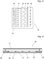
- Fig. 4 shows a further excerpt from the manufacturing process, namely how the second outer layer 12 is lowered onto the spacers 23.
- the viscous material application is slightly pressed or squeezed, so that finally (not shown) the separating elements 14 materially contact or connect the two outer layers 11, 12.
- the first outer layer 11 rests on the support 22.
- the filter device 10 with its outer layers 11, 12 can have different separating elements 14, depending on the area of application, the internal flow resistance of which can be adapted to the respective tasks.
- the outer layers 11, 12 can also have different thicknesses, also depending on the area of application of the filter device 10.
- the filter device 10 can also be provided with drainage openings, backwash openings, filtrate inflows and outflows at a wide variety of locations. With regard to the edge-side seal, socket strips, adhesives, rubber seals and the like can be used.
- the filter device 10 can have a round or angular design and be assembled in multiple layers or layers to form a filter stack.
Landscapes
- Chemical & Material Sciences (AREA)
- Chemical Kinetics & Catalysis (AREA)
- Inorganic Chemistry (AREA)
- Engineering & Computer Science (AREA)
- Manufacturing & Machinery (AREA)
- Filtering Materials (AREA)
Description
- Die Erfindung betrifft ein Verfahren zur Herstellung einer Filtervorrichtung, eine zur Durchführung dieses Verfahrens geeignete Fertigungsvorrichtung sowie eine Filtervorrichtung.
- Aus dem Stand der Technik sind verschiedene Filtervorrichtungen bekannt, die bisweilen auch als Plattenfilter bezeichnet werden.
- Die
US 5,730,869 A beschreibt z. B. einen Keramikfilter, für dessen Herstellung zwei gesinterte Keramikaußenlagen über keramische Stege und einen keramischen Außenring durch Versinterung zu einer homogenen Einheit miteinander verbunden werden. Der so hergestellte Filter eignet sich für spezielle Anwendungsbereiche, primär für den Bereich der Mikro- und Ultrafiltration, insbesondere auch für Anwendungen in organischen Lösungsmitteln und heißen, aggressiven Prozessmedien. Der Herstellungsvorgang ist relativ aufwändig und damit auch teuer. - Die
DE 10 2011 107 278 A1 beschreibt einen Keramikfilter, bei welchem angesinterte Distanzelemente aus mehreren Teilelementen bestehen, die einen sich im Wesentlichen linear in Richtung der Abflussöffnung erstreckenden Abschnitt umfassen, von dem aus mehrere zueinander parallel angeordneter Abschnitte abzweigen. Auch ein derartiger Filter ist in seiner Herstellung relativ kompliziert und kostenaufwendig, so dass er für weniger komplexe Anwendungsbereiche aus Kostengründen nicht mehr wirtschaftlich einsetzbar ist. - Die
DE 101 22 095 A1 beschreibt ein Membranelement mit einer Permeatablauföffnung. Dieses umfasst ein Trägerelement und eine auf beiden Seiten des Trägerelementes aufgebrachte Membran, die jeweils ebenfalls die Permeatablauföffnung enthalten. Die Oberfläche der Seiten des Trägerelements weist Strukturen auf, die der Zuführung des Permeats zur Permeatablauföffnung dienen und die als Membran verwendete Membranfolie stützen. Der äußere Rand des Trägerelements ist mit den Membranfolien verbunden. -
EP 2 818 230 A1 offenbart eine polymerbasierte Filtereinrichtung. - Der vorgenannte Stand der Technik ist insofern verbesserungswürdig, als die Filtervorrichtungen nur aufwändig und damit teuer herstellbar sind.
- Der Erfindung liegt daher die Aufgabe zugrunde, ein Verfahren aufzuzeigen, um möglichst günstig eine entsprechende Filtervorrichtung herzustellen, die aufgrund der günstigen Herstellung auch für die Anwendung in weniger aufwändigen Filteraufgaben geeignet ist.
- Diese Aufgabe wird durch ein Verfahren zur Herstellung einer keramischen Filtervorrichtung gemäß Anspruch 1 gelöst. Vorteilhafte Weiterbildungen ergeben sich aus den Unteransprüchen.
- Als Kern der Erfindung wird es angesehen, ein Verfahren vorzuschlagen mit Hilfe dessen eine keramische Filtervorrichtung fertigbar ist, die wenigstens zwei Außenlagen und eine dazwischen angeordnete und diese verbindende Zwischenlage umfasst, wobei zunächst eine erste Außenlage bereitgestellt wird, dann auf dieser eine Zwischenlage aufgebracht wird und anschließend wiederum auf der Zwischenlage eine zweite Außenlage aufgebracht wird. Erfindungswesentlich ist dabei, dass das Aufbringen der Zwischenlage dergestalt von statten geht, dass ein viskoses keramisches Material aufgetragen wird, wobei Teilbereiche der ersten Außenlage unbedeckt bleiben. Anders ausgedrückt: auf Teilbereichen der ersten Außenlage wird viskoses keramisches Material aufgetragen, auf anderen Teilbereichen der ersten Außenlage wird kein viskoses keramisches Material aufgetragen.
- Bei der Filtervorrichtung handelt es sich um eine keramische Filtervorrichtung; bei den Außenlagen handelt es sich demnach typischerweise um keramische Außenlagen, bei der Zwischenlage handelt es sich demnach typischerweise um eine keramische Zwischenlage.
- Als erster Schritt einer Fertigung der Filtervorrichtung können also zunächst zwei Außenlagen hergestellt werden - beispielsweise durch einen Stanzvorgang einer (keramischen) Grünfolie. Entsprechende, gegebenenfalls z. B. durch einen Stanzvorgang vorkonfektionierte Außenlagen können alternativ auch vorkonfektioniert bereitgestellt werden; die Herstellung der Außenlagen kann demnach auch in einem zu dem hier beschriebenen Verfahren gesonderten Herstellungsprozess erfolgen.
- Der Auftrag des keramischen Materials kann bahnförmig durchgehend oder unterbrochen, oder punktuell geschehen. Die Formgebung des Auftrags wird an die Anwendung des Filters angepasst, wohingegen das Fertigungsprinzip immer gleich bleibt. Dabei bildet der Materialauftrag des viskosen keramischen Materials eines oder mehrere Trennelemente aus, deren Form durch das aufgetragene viskose keramische Material bestimmbar oder bestimmt ist bzw. sind.
- In einem weiteren erfindungsgemäßen Verfahrensschritt wird die zweite Außenlage beim Aufbringen auf die Zwischenlage auf einen definierten Abstand zur ersten Außenlage gebracht. Dieser Abstand kann vorab in Abhängigkeit von den jeweiligen Endabmessungen der herzustellenden Filtervorrichtung, d. h. insbesondere von den Soll-Abmessungen der Filtervorrichtung nach einem Sintervorgang, bestimmt werden. Dies bedeutet, dass das aufgetragene viskose keramische Material zwischen den Außenlagen geringfügig gepresst oder gequetscht werden kann. Das Maß der Pressung bzw. Quetschung wird typischerweise im Hinblick auf die Soll-Abmessungen der Filtervorrichtung gewählt.
- In einer bevorzugten Ausführungsvariante wird dafür die zweite Außenlage relativ zur ersten Außenlage bewegt, wobei das punkt- und/oder bahnförmig aufgebrachte viskose keramische Material eine Formänderung, insbesondere auf das Sollmaß vor einem Sintervorgang, erfährt. Das Sollmaß vor einem Sintervorgang wird wiederum typischerweise im Hinblick auf die Soll-Abmessungen der Filtervorrichtung gewählt.
- Vorzugsweise erfolgt das punkt- oder bahnförmige Auftragen des viskosen keramischen Materials mittels wenigstens einer Düse, die weiterhin bevorzugt in wenigstens einem Bewegungsfreiheitsgrad relativ zu der ersten Außenlage bewegbar gelagert ist und in x-, y- und z-Richtung relativ zur ersten Außenlage positioniert werden kann. Vorzugsweise erfolgt diese Positionierung über eine Steuereinheit. In einer weiteren bevorzugten Ausführungsform wird die die erste Außenlage aufnehmende Auflage relativ zu einer Düse bewegbar gelagert. In einer weiteren bevorzugten Ausführungsform wird sowohl die Düse als auch die die erste Außenlage aufnehmende Auflage bewegbar gelagert. Eine Bewegung der baulichen Komponenten erfolgt vorzugsweise über eine Steuerung. In einer weiteren bevorzugten Ausführungsform umfasst die Fertigungsvorrichtung eine Steuerung zur Positionierung der Düse und/oder der Auflage in x-, y- und/oder z-Richtung. Die Steuerung kann mit wenigstens einem Antrieb zusammenwirken, über welchen eine die Düse und/oder die die erste Außenlage aufnehmende Auflage in eine Bewegung versetzende Antriebskraft erzeugbar ist.
- Die Viskosität des aufzutragenden keramischen Materials kann in Abhängigkeit der Form des Materialauftrags unterschiedlich gewählt werden. Der Viskositätsbereich unter typischen Umgebungsbedingungen ist typischerweise pastös. Der Viskositätsbereich ist typischerweise so gewählt, dass das keramische Material nach dem Auftrag eine gewisse Formstabilität aufweist, d. h. insbesondere nicht flächig zerfließt. Der Auftrag des keramischen Materials erfolgt dabei typischerweise raupenförmig, d. h. das keramische Material wird typischerweise als formstabile raupenartige bzw. raupenförmige Bahn aufgetragen. Eine raupenartige bzw. -förmige Bahn definiert sich typischerweise durch eine zumindest abschnittsweise, insbesondere kreissegmentartig, gebogen bzw. gewölbt verlaufende Querschnittsgeometrie.
- Ebenso ist es möglich, die Viskosität an die Fertigungsumgebung wie beispielsweise Temperatur oder Luftfeuchtigkeit anzupassen, da entsprechende Fertigungsräume möglicherweise jahreszeitenbedingt unterschiedliche Umgebungsbedingungen bieten, die möglicherweise kostengünstiger über den Materialauftrag als über die Sicherstellung konstanter Umgebungsluftbedingungen gewährleistet werden kann.
- Vorstehend beschriebene Verfahrensschritte sind geeignet, einen mehrlagigen sinterfähigen (keramischen) Körper auszubilden. Der so ausgebildete (mindestens) dreilagige Körper kann anschließend in einem gemeinsamen Sinterprozess gesintert werden. Dafür ist es vorteilhaft, bereits die erste Außenlage auf einer Auflage zu positionieren, die nach dem Aufbau des mehrlagigen sinterfähigen Körpers in einen Sinterofen verbracht werden kann. Dementsprechend umfasst die erfindungsgemäße Fertigungsvorrichtung eine Auflage zum Auflegen der ersten Außenlage, wenigstens eine Düse zum Auftragen des viskosen keramischen Materials, einen oder mehrere Abstandshalter zum Bestimmen und Halten des Abstandes zwischen den beiden Außenlagen sowie Mittel zur Verbringung der auf der Auflage angeordneten Außenlagen und der dazwischen angeordneten Zwischenlage in einen Sinterofen.
- In einer weiteren bevorzugten Ausführungsform sind die Abstandshalter bewegbar relativ zueinander gelagert, insbesondere derart, dass punkt- und/oder bahnförmig aufgebrachtes viskoses keramisches Material eine Formänderung, insbesondere auf ein Sollmaß vor einem Sintervorgang, erfährt. Dementsprechend umfasst die erfindungsgemäße Filtervorrichtung mindestens zwei Außenlagen und eine dazwischen angeordnete Zwischenlage, die aus einem oder mehreren Trennelementen besteht, die Linienform(en), Punktform oder beliebige Freiform(en) einnehmen können.
- Die Außenlagen sind aus keramischem Material, d. h. z. B Aluminiumoxid (Al2O3), gebildet, wobei das keramische Material der Außenlagen identisch sein kann und identisch mit dem keramischen Material der Zwischenlage sein kann. Ebenso ist denkbar, dass unterschiedliche keramische Materialien verwendet werden.
- Die Außenlagen sind flächenartig bzw. -förmig ausgebildet. Die Flächenform beinhaltet typischerweise eine ebene geometrische Gestalt.
- Ein derartiger Filter ist aufgrund der einfachen Struktur der Filteraußenlagen und des immer gleichen Prinzips der Schichtbildung günstig herstellbar. Der beschriebene Herstellung ist schnell umsetzbar und damit preisgünstig, wobei die Formgebung (z. B. Linienführung) der Zwischenlage der jeweiligen Verwendung angepasst werden kann, so dass bei der Verwendung identischer Außenlagen die Form an spezielle Aufgabenbereiche angepasst werden kann, ohne das eigentliche Konstruktions- und Herstellungsprinzip ändern zu müssen.
- Die erfindungsgemäße Filtervorrichtung kann als Einzelplattenfiltervorrichtung eingesetzt werden oder aber auch als stackartig aufgebaute Mehrplattenanordnung.
- Die Erfindung ist anhand von Ausführungsbeispielen in den Zeichnungsfiguren näher erläutert. Dabei zeigen:
- Fig. 1
- einen Schnitt durch eine erste Ausführungsform der erfindungsgemäßen Filtervorrichtung;
- Fig. 2
- einen Ausschnitt aus dem Fertigungsprozess;
- Fig. 3
- beispielhafte Formgebungen der Trennelemente der Zwischenlage; und
- Fig. 4
- einen weiteren Ausschnitt aus dem Fertigungsprozess.
- In
Fig. 1 erkennt man einen Schnitt durch eine erste beispielhafte Ausführungsform einer erfindungsgemäßen Filtervorrichtung 10 mit einer ersten Außenlage 11, einer Zwischenlage 13 und einer zweiten Außenlage 12. Die Zwischenlage 13 umfasst mehrere Trennelemente 14, die angedeutet in Linienform angeordnet sind. -
Fig. 2 zeigt den Verfahrensschritt, während dessen die Zwischenlage13 in Gestalt des viskosen keramischen Materials als Trennelemente 14 aufgetragen wird. - In
Fig. 3 sind beispielhafte Formgebungen der Trennelemente 14 der Zwischenlage 13 zu erkennen. Im Rahmen der Ansprüche sind generell alle beliebigen geometrischen Anordnungen, Formen und Längen denkbar. -
Fig. 4 zeigt einen weiteren Ausschnitt aus dem Fertigungsprozess, nämlich wie die zweite Außenlage 12 auf die Abstandshalter 23 abgesenkt wird. Dabei wird der viskose Materialauftrag leicht gepresst bzw. gequetscht, so dass schließlich (nicht dargestellt), die Trennelemente 14 die beiden Außenlagen 11, 12 stofflich kontaktieren bzw. verbinden. Die erste Außenlage 11 ruht auf der Auflage 22. - Abschließend sei nochmals angemerkt, dass die Filtervorrichtung 10 mit ihren Außenlagen 11, 12 je nach Anwendungsbereich unterschiedliche Trennelemente 14 aufweisen kann, deren Durchfluss-Innenwiederstand an die jeweiligen Aufgaben angepasst werden kann. Auch die Außenlagen 11, 12 können unterschiedliche Stärken aufweisen, ebenfalls abhängig vom Einsatzbereich der Filtervorrichtung 10. Die Filtervorrichtung 10 kann ferner an unterschiedlichsten Stellen mit Drainageöffnungen, Rückspülöffnungen, Filtratzuflüssen und - abflüssen versehen sein. Hinsichtlich der randseitigen Dichtung können Steckleisten, Verklebungen, Gummidichtungen und dgl. eingesetzt werden.
- Die Filtervorrichtung 10 kann rund oder eckig ausgebildet sein und mehrlagig bzw. -schichtig zu einem Filterstack zusammengebaut sein.
Claims (10)
- Verfahren zum Herstellen einer keramischen Filtervorrichtung (10), umfassend wenigstens zwei Außenlagen (11, 12), zwischen welchen eine die beiden Außenlagen (11, 12) miteinander verbindenden Zwischenlage (13) angeordnet oder ausgebildet ist, gekennzeichnet durch die folgenden Schritte:- Bereitstellen einer ersten Außenlage (11),- Aufbringen einer Zwischenlage (13) auf der ersten Außenlage (11), wobei Teilbereiche der ersten Außenlage (11) unbedeckt bleiben,- Aufbringen einer zweiten Außenlage (12) auf der Zwischenlage (13),wobei das Aufbringen der Zwischenlage (13) ein punkt- und/oder bahnförmiges Auftragen eines viskosen keramischen Materials umfasst, wobei die erste und die zweite Außenlage (11, 12) als flächige keramische Körper, insbesondere als keramische Platten, bereitgestellt werden,wobei die Außenlagen (11, 12) und die dazwischen angeordnete Zwischenlage (13) in einen Ofen verbracht werden und in einem Sinterprozess behandelt werden.
- Verfahren nach Anspruch 1, dadurch gekennzeichnet, dass die Zwischenlage (13) eines oder mehrere, Trennelemente (14) umfasst, deren Form durch das aufgetragene viskose keramische Material bestimmt ist oder sind.
- Verfahren nach Anspruch 1 oder 2, dadurch gekennzeichnet, dass die Zwischenlage (13) eines oder mehrere, insbesondere punktförmige, Stützelemente (14) umfasst, deren Form durch das aufgetragene viskose keramische Material bestimmt ist oder sind.
- Verfahren nach einem der Ansprüche 1 bis 3, dadurch gekennzeichnet, dass die zweite Außenlage (12) nach dem Aufbringen auf die Zwischenlage (13) auf einen definierten Abstand zur ersten Außenlage (11) gebracht wird.
- Verfahren nach Ansprüche 4, dadurch gekennzeichnet, dass die zweite Außenlage (12) relativ zur ersten Außenlage (11) bewegt wird, wobei das punkt- und/oder bahnförmig aufgebrachte viskose keramische Material eine Formänderung, insbesondere auf ein Sollmaß vor einem Sintervorgang, erfährt.
- Verfahren nach einem der Ansprüche 1 bis 5, dadurch gekennzeichnet, dass das punkt- und/oder bahnförmige Auftragen des viskosen keramischen Materials mittels wenigstens einer in wenigstens einem Bewegungsfreiheitsgrad relativ zu der ersten Außenlage (11) bewegbar gelagerten Düse (21) geschieht.
- Verfahren nach einem der Ansprüche 1 bis 5, dadurch gekennzeichnet, dass die die erste Außenlage (11) aufnehmende Auflage (22) bewegbar gelagert ist.
- Verfahren nach einem der Ansprüche 1 bis 5, dadurch gekennzeichnet, dass die Düse (21) und die die erste Außenlage (11) aufnehmende Auflage (22) bewegbar gelagert ist.
- Verfahren nach einem der vorhergehenden Ansprüche, dadurch gekennzeichnet, dass das bahnartige Auftragen des viskosen keramischen Materials in der Form gerader Linien und/oder freigeformter Linien erfolgt.
- Verfahren nach einem der vorhergehenden Ansprüche, dadurch gekennzeichnet, dass das Auftragen des viskosen keramischen Materials in punktueller Form erfolgt.
Priority Applications (1)
| Application Number | Priority Date | Filing Date | Title |
|---|---|---|---|
| EP18157857.6A EP3530343B1 (de) | 2018-02-21 | 2018-02-21 | Verfahren zur herstellung einer keramischen filtervorrichtung |
Applications Claiming Priority (1)
| Application Number | Priority Date | Filing Date | Title |
|---|---|---|---|
| EP18157857.6A EP3530343B1 (de) | 2018-02-21 | 2018-02-21 | Verfahren zur herstellung einer keramischen filtervorrichtung |
Publications (2)
| Publication Number | Publication Date |
|---|---|
| EP3530343A1 EP3530343A1 (de) | 2019-08-28 |
| EP3530343B1 true EP3530343B1 (de) | 2021-10-06 |
Family
ID=61256682
Family Applications (1)
| Application Number | Title | Priority Date | Filing Date |
|---|---|---|---|
| EP18157857.6A Active EP3530343B1 (de) | 2018-02-21 | 2018-02-21 | Verfahren zur herstellung einer keramischen filtervorrichtung |
Country Status (1)
| Country | Link |
|---|---|
| EP (1) | EP3530343B1 (de) |
Family Cites Families (5)
| Publication number | Priority date | Publication date | Assignee | Title |
|---|---|---|---|---|
| DE4330163C2 (de) * | 1993-09-07 | 1996-01-18 | Koppe Franz | Poröser Keramikfilter |
| US5730869A (en) | 1995-01-28 | 1998-03-24 | Koppe; Franz | Porous ceramic filter |
| DE10122095A1 (de) | 2001-05-07 | 2002-11-14 | Creavis Tech & Innovation Gmbh | Membranelemente und ein Verfahren zu deren Herstellung |
| DE102011107278B4 (de) | 2011-07-06 | 2016-03-03 | Kerafol Keramische Folien Gmbh | Poröser Keramikfilter |
| KR101966761B1 (ko) * | 2012-02-24 | 2019-04-08 | 도레이 카부시키가이샤 | 분리막 엘리먼트 및 분리막 모듈 |
-
2018
- 2018-02-21 EP EP18157857.6A patent/EP3530343B1/de active Active
Also Published As
| Publication number | Publication date |
|---|---|
| EP3530343A1 (de) | 2019-08-28 |
Similar Documents
| Publication | Publication Date | Title |
|---|---|---|
| DE2443926C2 (de) | Mehrlagiger für Strömungsmittel durchlässiger Körper und Verfahren zur Herstellung desselben und seiner Lagen | |
| WO2008071351A1 (de) | Vorrichtung zur aufnahme oder manipulation einer flüssigkeit | |
| DE102012012711A1 (de) | Verfahren zur Herstellung eines Niederdruck- Dünnwandwärmetauschers und Dünnwandwärmetauscher | |
| EP3300792A2 (de) | Verfahren zur herstellung einer keramischen filtrationsscheibe | |
| EP1476907B1 (de) | Piezoaktor mit strukturierter aussenelektrode | |
| DE102008002492A1 (de) | Faltaktor oder Faltsensor sowie Herstellungsverfahren für einen Faltaktor oder Faltsensor | |
| WO2000004317A1 (de) | Fliesskanalwand | |
| DE102006059459A1 (de) | Vorrichtung zur Aufnahme oder Manipulation einer Flüssigkeit | |
| DE3708569A1 (de) | Waermeisolatormaterial und verfahren zu seiner herstellung | |
| DE102013203656A1 (de) | Mikrofluidisches Drehventil | |
| CH705539A1 (de) | Dielektrischer Aktor. | |
| EP2910299A1 (de) | Platten- oder scheibenartige Filtereinrichtung | |
| WO2020109537A1 (de) | Verfahren zur herstellung einer rotorblatthalbwurzel und eine herstellungsform dafür | |
| DE102009002631A1 (de) | Piezoelektrischer Antrieb und Mikroventil mit einem solchen | |
| DE102008062678B4 (de) | Verbundbauteil mit einer Wabenstruktur | |
| EP3671159B1 (de) | Körper hergestellt durch additives herstellungsverfahren und verfahren zur herstellung des körpers | |
| EP3530343A1 (de) | Verfahren zur herstellung einer keramischen filtervorrichtung, fertigungsvorrichtung zur durchführung des verfahrens und filtervorrichtung | |
| WO2002089950A2 (de) | Membranelemente und ein verfahren zu deren herstellung | |
| DE102018123980A1 (de) | Verfahren zur Herstellung einer Hülse für eine hydraulische Spannbuchse sowie hydromechanisch spannbare Buchse | |
| DE102014018481A1 (de) | Keramische Filtermembran und Filtermodul | |
| EP1779916A1 (de) | Extrudierte Dichtung | |
| DE4339962A1 (de) | Vorrichtung und Verfahren zur Herstellung von Sickenblechen mit planparallelen Außenkantenflächen | |
| EP3497357B1 (de) | Ventil aus einem keramischen werkstoff und ein verfahren zu seiner herstellung | |
| WO2020249348A1 (de) | Fluidleitungsteil für eine mikrofluidische vorrichtung, mikrofluidische vorrichtung und verfahren zur fertigung einer mikrofluidischen vorrichtung | |
| WO2017008922A1 (de) | Farbübertragungsmedium |
Legal Events
| Date | Code | Title | Description |
|---|---|---|---|
| PUAI | Public reference made under article 153(3) epc to a published international application that has entered the european phase |
Free format text: ORIGINAL CODE: 0009012 |
|
| STAA | Information on the status of an ep patent application or granted ep patent |
Free format text: STATUS: THE APPLICATION HAS BEEN PUBLISHED |
|
| AK | Designated contracting states |
Kind code of ref document: A1 Designated state(s): AL AT BE BG CH CY CZ DE DK EE ES FI FR GB GR HR HU IE IS IT LI LT LU LV MC MK MT NL NO PL PT RO RS SE SI SK SM TR |
|
| AX | Request for extension of the european patent |
Extension state: BA ME |
|
| STAA | Information on the status of an ep patent application or granted ep patent |
Free format text: STATUS: REQUEST FOR EXAMINATION WAS MADE |
|
| 17P | Request for examination filed |
Effective date: 20200131 |
|
| RBV | Designated contracting states (corrected) |
Designated state(s): AL AT BE BG CH CY CZ DE DK EE ES FI FR GB GR HR HU IE IS IT LI LT LU LV MC MK MT NL NO PL PT RO RS SE SI SK SM TR |
|
| STAA | Information on the status of an ep patent application or granted ep patent |
Free format text: STATUS: EXAMINATION IS IN PROGRESS |
|
| 17Q | First examination report despatched |
Effective date: 20210302 |
|
| GRAP | Despatch of communication of intention to grant a patent |
Free format text: ORIGINAL CODE: EPIDOSNIGR1 |
|
| STAA | Information on the status of an ep patent application or granted ep patent |
Free format text: STATUS: GRANT OF PATENT IS INTENDED |
|
| INTG | Intention to grant announced |
Effective date: 20210714 |
|
| GRAS | Grant fee paid |
Free format text: ORIGINAL CODE: EPIDOSNIGR3 |
|
| GRAA | (expected) grant |
Free format text: ORIGINAL CODE: 0009210 |
|
| STAA | Information on the status of an ep patent application or granted ep patent |
Free format text: STATUS: THE PATENT HAS BEEN GRANTED |
|
| AK | Designated contracting states |
Kind code of ref document: B1 Designated state(s): AL AT BE BG CH CY CZ DE DK EE ES FI FR GB GR HR HU IE IS IT LI LT LU LV MC MK MT NL NO PL PT RO RS SE SI SK SM TR |
|
| REG | Reference to a national code |
Ref country code: GB Ref legal event code: FG4D Free format text: NOT ENGLISH |
|
| REG | Reference to a national code |
Ref country code: CH Ref legal event code: EP Ref country code: AT Ref legal event code: REF Ref document number: 1435742 Country of ref document: AT Kind code of ref document: T Effective date: 20211015 |
|
| REG | Reference to a national code |
Ref country code: IE Ref legal event code: FG4D Free format text: LANGUAGE OF EP DOCUMENT: GERMAN |
|
| REG | Reference to a national code |
Ref country code: DE Ref legal event code: R096 Ref document number: 502018007329 Country of ref document: DE |
|
| REG | Reference to a national code |
Ref country code: LT Ref legal event code: MG9D |
|
| REG | Reference to a national code |
Ref country code: NL Ref legal event code: MP Effective date: 20211006 |
|
| PG25 | Lapsed in a contracting state [announced via postgrant information from national office to epo] |
Ref country code: RS Free format text: LAPSE BECAUSE OF FAILURE TO SUBMIT A TRANSLATION OF THE DESCRIPTION OR TO PAY THE FEE WITHIN THE PRESCRIBED TIME-LIMIT Effective date: 20211006 Ref country code: LT Free format text: LAPSE BECAUSE OF FAILURE TO SUBMIT A TRANSLATION OF THE DESCRIPTION OR TO PAY THE FEE WITHIN THE PRESCRIBED TIME-LIMIT Effective date: 20211006 Ref country code: FI Free format text: LAPSE BECAUSE OF FAILURE TO SUBMIT A TRANSLATION OF THE DESCRIPTION OR TO PAY THE FEE WITHIN THE PRESCRIBED TIME-LIMIT Effective date: 20211006 Ref country code: BG Free format text: LAPSE BECAUSE OF FAILURE TO SUBMIT A TRANSLATION OF THE DESCRIPTION OR TO PAY THE FEE WITHIN THE PRESCRIBED TIME-LIMIT Effective date: 20220106 |
|
| PG25 | Lapsed in a contracting state [announced via postgrant information from national office to epo] |
Ref country code: IS Free format text: LAPSE BECAUSE OF FAILURE TO SUBMIT A TRANSLATION OF THE DESCRIPTION OR TO PAY THE FEE WITHIN THE PRESCRIBED TIME-LIMIT Effective date: 20220206 Ref country code: SE Free format text: LAPSE BECAUSE OF FAILURE TO SUBMIT A TRANSLATION OF THE DESCRIPTION OR TO PAY THE FEE WITHIN THE PRESCRIBED TIME-LIMIT Effective date: 20211006 Ref country code: PT Free format text: LAPSE BECAUSE OF FAILURE TO SUBMIT A TRANSLATION OF THE DESCRIPTION OR TO PAY THE FEE WITHIN THE PRESCRIBED TIME-LIMIT Effective date: 20220207 Ref country code: PL Free format text: LAPSE BECAUSE OF FAILURE TO SUBMIT A TRANSLATION OF THE DESCRIPTION OR TO PAY THE FEE WITHIN THE PRESCRIBED TIME-LIMIT Effective date: 20211006 Ref country code: NO Free format text: LAPSE BECAUSE OF FAILURE TO SUBMIT A TRANSLATION OF THE DESCRIPTION OR TO PAY THE FEE WITHIN THE PRESCRIBED TIME-LIMIT Effective date: 20220106 Ref country code: NL Free format text: LAPSE BECAUSE OF FAILURE TO SUBMIT A TRANSLATION OF THE DESCRIPTION OR TO PAY THE FEE WITHIN THE PRESCRIBED TIME-LIMIT Effective date: 20211006 Ref country code: LV Free format text: LAPSE BECAUSE OF FAILURE TO SUBMIT A TRANSLATION OF THE DESCRIPTION OR TO PAY THE FEE WITHIN THE PRESCRIBED TIME-LIMIT Effective date: 20211006 Ref country code: HR Free format text: LAPSE BECAUSE OF FAILURE TO SUBMIT A TRANSLATION OF THE DESCRIPTION OR TO PAY THE FEE WITHIN THE PRESCRIBED TIME-LIMIT Effective date: 20211006 Ref country code: GR Free format text: LAPSE BECAUSE OF FAILURE TO SUBMIT A TRANSLATION OF THE DESCRIPTION OR TO PAY THE FEE WITHIN THE PRESCRIBED TIME-LIMIT Effective date: 20220107 Ref country code: ES Free format text: LAPSE BECAUSE OF FAILURE TO SUBMIT A TRANSLATION OF THE DESCRIPTION OR TO PAY THE FEE WITHIN THE PRESCRIBED TIME-LIMIT Effective date: 20211006 |
|
| REG | Reference to a national code |
Ref country code: DE Ref legal event code: R097 Ref document number: 502018007329 Country of ref document: DE |
|
| PG25 | Lapsed in a contracting state [announced via postgrant information from national office to epo] |
Ref country code: SM Free format text: LAPSE BECAUSE OF FAILURE TO SUBMIT A TRANSLATION OF THE DESCRIPTION OR TO PAY THE FEE WITHIN THE PRESCRIBED TIME-LIMIT Effective date: 20211006 Ref country code: SK Free format text: LAPSE BECAUSE OF FAILURE TO SUBMIT A TRANSLATION OF THE DESCRIPTION OR TO PAY THE FEE WITHIN THE PRESCRIBED TIME-LIMIT Effective date: 20211006 Ref country code: RO Free format text: LAPSE BECAUSE OF FAILURE TO SUBMIT A TRANSLATION OF THE DESCRIPTION OR TO PAY THE FEE WITHIN THE PRESCRIBED TIME-LIMIT Effective date: 20211006 Ref country code: EE Free format text: LAPSE BECAUSE OF FAILURE TO SUBMIT A TRANSLATION OF THE DESCRIPTION OR TO PAY THE FEE WITHIN THE PRESCRIBED TIME-LIMIT Effective date: 20211006 Ref country code: DK Free format text: LAPSE BECAUSE OF FAILURE TO SUBMIT A TRANSLATION OF THE DESCRIPTION OR TO PAY THE FEE WITHIN THE PRESCRIBED TIME-LIMIT Effective date: 20211006 Ref country code: CZ Free format text: LAPSE BECAUSE OF FAILURE TO SUBMIT A TRANSLATION OF THE DESCRIPTION OR TO PAY THE FEE WITHIN THE PRESCRIBED TIME-LIMIT Effective date: 20211006 |
|
| PLBE | No opposition filed within time limit |
Free format text: ORIGINAL CODE: 0009261 |
|
| STAA | Information on the status of an ep patent application or granted ep patent |
Free format text: STATUS: NO OPPOSITION FILED WITHIN TIME LIMIT |
|
| 26N | No opposition filed |
Effective date: 20220707 |
|
| PG25 | Lapsed in a contracting state [announced via postgrant information from national office to epo] |
Ref country code: MC Free format text: LAPSE BECAUSE OF FAILURE TO SUBMIT A TRANSLATION OF THE DESCRIPTION OR TO PAY THE FEE WITHIN THE PRESCRIBED TIME-LIMIT Effective date: 20211006 |
|
| REG | Reference to a national code |
Ref country code: CH Ref legal event code: PL |
|
| REG | Reference to a national code |
Ref country code: BE Ref legal event code: MM Effective date: 20220228 |
|
| PG25 | Lapsed in a contracting state [announced via postgrant information from national office to epo] |
Ref country code: LU Free format text: LAPSE BECAUSE OF NON-PAYMENT OF DUE FEES Effective date: 20220221 Ref country code: AL Free format text: LAPSE BECAUSE OF FAILURE TO SUBMIT A TRANSLATION OF THE DESCRIPTION OR TO PAY THE FEE WITHIN THE PRESCRIBED TIME-LIMIT Effective date: 20211006 |
|
| PG25 | Lapsed in a contracting state [announced via postgrant information from national office to epo] |
Ref country code: SI Free format text: LAPSE BECAUSE OF FAILURE TO SUBMIT A TRANSLATION OF THE DESCRIPTION OR TO PAY THE FEE WITHIN THE PRESCRIBED TIME-LIMIT Effective date: 20211006 |
|
| PG25 | Lapsed in a contracting state [announced via postgrant information from national office to epo] |
Ref country code: LI Free format text: LAPSE BECAUSE OF NON-PAYMENT OF DUE FEES Effective date: 20220228 Ref country code: IE Free format text: LAPSE BECAUSE OF NON-PAYMENT OF DUE FEES Effective date: 20220221 Ref country code: CH Free format text: LAPSE BECAUSE OF NON-PAYMENT OF DUE FEES Effective date: 20220228 |
|
| PG25 | Lapsed in a contracting state [announced via postgrant information from national office to epo] |
Ref country code: BE Free format text: LAPSE BECAUSE OF NON-PAYMENT OF DUE FEES Effective date: 20220228 |
|
| PGFP | Annual fee paid to national office [announced via postgrant information from national office to epo] |
Ref country code: AT Payment date: 20230215 Year of fee payment: 6 |
|
| PG25 | Lapsed in a contracting state [announced via postgrant information from national office to epo] |
Ref country code: IT Free format text: LAPSE BECAUSE OF FAILURE TO SUBMIT A TRANSLATION OF THE DESCRIPTION OR TO PAY THE FEE WITHIN THE PRESCRIBED TIME-LIMIT Effective date: 20211006 |
|
| PGFP | Annual fee paid to national office [announced via postgrant information from national office to epo] |
Ref country code: GB Payment date: 20230221 Year of fee payment: 6 |
|
| P01 | Opt-out of the competence of the unified patent court (upc) registered |
Effective date: 20230525 |
|
| PG25 | Lapsed in a contracting state [announced via postgrant information from national office to epo] |
Ref country code: MK Free format text: LAPSE BECAUSE OF FAILURE TO SUBMIT A TRANSLATION OF THE DESCRIPTION OR TO PAY THE FEE WITHIN THE PRESCRIBED TIME-LIMIT Effective date: 20211006 Ref country code: CY Free format text: LAPSE BECAUSE OF FAILURE TO SUBMIT A TRANSLATION OF THE DESCRIPTION OR TO PAY THE FEE WITHIN THE PRESCRIBED TIME-LIMIT Effective date: 20211006 |
|
| PG25 | Lapsed in a contracting state [announced via postgrant information from national office to epo] |
Ref country code: HU Free format text: LAPSE BECAUSE OF FAILURE TO SUBMIT A TRANSLATION OF THE DESCRIPTION OR TO PAY THE FEE WITHIN THE PRESCRIBED TIME-LIMIT; INVALID AB INITIO Effective date: 20180221 |
|
| PG25 | Lapsed in a contracting state [announced via postgrant information from national office to epo] |
Ref country code: MT Free format text: LAPSE BECAUSE OF FAILURE TO SUBMIT A TRANSLATION OF THE DESCRIPTION OR TO PAY THE FEE WITHIN THE PRESCRIBED TIME-LIMIT Effective date: 20211006 |
|
| REG | Reference to a national code |
Ref country code: AT Ref legal event code: MM01 Ref document number: 1435742 Country of ref document: AT Kind code of ref document: T Effective date: 20240221 |
|
| GBPC | Gb: european patent ceased through non-payment of renewal fee |
Effective date: 20240221 |
|
| PG25 | Lapsed in a contracting state [announced via postgrant information from national office to epo] |
Ref country code: AT Free format text: LAPSE BECAUSE OF NON-PAYMENT OF DUE FEES Effective date: 20240221 |
|
| PG25 | Lapsed in a contracting state [announced via postgrant information from national office to epo] |
Ref country code: AT Free format text: LAPSE BECAUSE OF NON-PAYMENT OF DUE FEES Effective date: 20240221 |
|
| PG25 | Lapsed in a contracting state [announced via postgrant information from national office to epo] |
Ref country code: GB Free format text: LAPSE BECAUSE OF NON-PAYMENT OF DUE FEES Effective date: 20240221 |
|
| PG25 | Lapsed in a contracting state [announced via postgrant information from national office to epo] |
Ref country code: GB Free format text: LAPSE BECAUSE OF NON-PAYMENT OF DUE FEES Effective date: 20240221 |
|
| PG25 | Lapsed in a contracting state [announced via postgrant information from national office to epo] |
Ref country code: TR Free format text: LAPSE BECAUSE OF FAILURE TO SUBMIT A TRANSLATION OF THE DESCRIPTION OR TO PAY THE FEE WITHIN THE PRESCRIBED TIME-LIMIT Effective date: 20211006 |
|
| PGFP | Annual fee paid to national office [announced via postgrant information from national office to epo] |
Ref country code: DE Payment date: 20260224 Year of fee payment: 9 |
|
| PGFP | Annual fee paid to national office [announced via postgrant information from national office to epo] |
Ref country code: FR Payment date: 20260223 Year of fee payment: 9 |