EP3530552A1 - Cabine de conducteur - Google Patents
Cabine de conducteur Download PDFInfo
- Publication number
- EP3530552A1 EP3530552A1 EP18211611.1A EP18211611A EP3530552A1 EP 3530552 A1 EP3530552 A1 EP 3530552A1 EP 18211611 A EP18211611 A EP 18211611A EP 3530552 A1 EP3530552 A1 EP 3530552A1
- Authority
- EP
- European Patent Office
- Prior art keywords
- driver
- cab according
- axis
- footrest
- cab
- Prior art date
- Legal status (The legal status is an assumption and is not a legal conclusion. Google has not performed a legal analysis and makes no representation as to the accuracy of the status listed.)
- Granted
Links
Images

Classifications
-
- B—PERFORMING OPERATIONS; TRANSPORTING
- B60—VEHICLES IN GENERAL
- B60N—SEATS SPECIALLY ADAPTED FOR VEHICLES; VEHICLE PASSENGER ACCOMMODATION NOT OTHERWISE PROVIDED FOR
- B60N3/00—Arrangements or adaptations of other passenger fittings, not otherwise provided for
- B60N3/06—Arrangements or adaptations of other passenger fittings, not otherwise provided for of footrests
-
- B—PERFORMING OPERATIONS; TRANSPORTING
- B60—VEHICLES IN GENERAL
- B60N—SEATS SPECIALLY ADAPTED FOR VEHICLES; VEHICLE PASSENGER ACCOMMODATION NOT OTHERWISE PROVIDED FOR
- B60N2/00—Seats specially adapted for vehicles; Arrangement or mounting of seats in vehicles
- B60N2/24—Seats specially adapted for vehicles; Arrangement or mounting of seats in vehicles for particular purposes or particular vehicles
-
- B—PERFORMING OPERATIONS; TRANSPORTING
- B60—VEHICLES IN GENERAL
- B60N—SEATS SPECIALLY ADAPTED FOR VEHICLES; VEHICLE PASSENGER ACCOMMODATION NOT OTHERWISE PROVIDED FOR
- B60N2/00—Seats specially adapted for vehicles; Arrangement or mounting of seats in vehicles
- B60N2/24—Seats specially adapted for vehicles; Arrangement or mounting of seats in vehicles for particular purposes or particular vehicles
- B60N2/38—Seats specially adapted for vehicles; Arrangement or mounting of seats in vehicles for particular purposes or particular vehicles specially constructed for use on tractors or like off-road vehicles
Definitions
- the present invention relates to a driver's cab, in particular for an agricultural working machine such as a combine harvester or a forage harvester.
- Such work machines generally carry on their front a working implement such as a header, which must be observed from the driver's cabin exactly.
- the driver's cab of the machine may have a windscreen that extends continuously between a roof and a floor panel of the cab and horizontally over its entire width and possibly also reaches out to the side flanks of the cab.
- the object of the invention is to provide a driver's cab that allows the driver comfortable changing postures while avoiding restrictions of the view as far as possible.
- a footrest is mounted in a cab for an agricultural machine on the left and right side of a center column, which is pivotable between a waiting position and a use position.
- a waiting position a waiting position
- a use position it may not be completely avoided that the footrests are visible to the driver and restrict the view through a windshield, but since they need not extend further sideways than required to place the feet, they in particular do not affect the clear view of the left and right edges of a work implement mounted on the work machine to safely navigate the work machine.
- While the footrests in the use position of The center column should each be spread sideways in order to support the driver's feet, they can only reach a waiting position by pivoting, in which they are closer than in the use position adjacent to the center column and in which they limit the view even less than in the usage position.
- the driver's cab can, in a manner known per se, have a steering column which carries a steering wheel, a joystick or another instrument for controlling the direction of travel and / or speed of the working machine.
- a steering column inevitably blocks part of the driver's field of vision. If the above-mentioned center column is identical to such a steering column or overlaps with the steering column from the driver's viewpoint, the restriction of the clear view through the center pillar can be further minimized.
- Each footrest should have a Wennaufstell structure, which is at least in the use position farther from the center column than the axis about which the footrest is pivotable.
- the footrests are pivotable about an axis oriented in the vehicle longitudinal direction.
- the pivotal movement is necessarily associated with an increase or decrease of the footrests, and the transition between waiting position and use position can be driven in one direction by gravity.
- the footrests are raised in the waiting position from the use position, ie the by Gravity driven transition is from the waiting to the use position.
- a locking means may be provided.
- An actuating element for unlocking the latching means may be arranged on the center column. Preferably, it is placed below the axis of the footrest so that it is easily accessible and operable with one foot.
- the actuating element and the locking means each form an arm of a two-armed lever, wherein the arm forming the actuating element comprises at least one first leg extending downwards from the axis of the lever along the central column. Such a leg can be actuated by pressing it with the foot against the center column.
- the lower end of the leg can be widened plate-shaped.
- the actuator is angled and further includes a second leg extending from a lower end of the first leg away from the center pillar.
- a leg can be actuated by being lifted by the foot or, preferably, depressed.
- a compression spring may be mounted between the first leg and the center column to keep the first leg, when the actuating element is not actuated, spread apart from the center column.
- the acting as a locking means lever arm may extend in height of the axis of the center column away.
- the axis of the two-armed lever and the axis of the footrest are preferably mounted in a same fitting part.
- Such a fitting part can be fastened to the center column at different elevations in order to allow the driver to adjust the height of the footrest to his personal preferences.
- the footrest may be formed as a hollow body with a serving in the use position upper, as a support surface of the feet wall portion and a lower wall in the use position. If this hollow body has an open, near-axis end, this can be used for locking the footrest in the waiting position by the locking means engages in the open end of the hollow body.
- the lower wall portion In the waiting position, when the footrest is folded substantially in the vertical, the lower wall portion preferably extends downwardly beyond the upper wall portion. Thus, it can be ensured that a stop surface which blocks the lower wall portion of the use position, does not cooperate with the upper wall portion before reaching the use position.
- Such a stop surface can cooperate in particular with an edge of the lower wall portion.
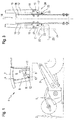
- Fig. 1 shows the front half of a combine harvester.
- the combine harvester carries at the front of its body a replaceable implement such as a grain cutter 1 for cutting and gathering crop material 2.
- a feederhouse 3 conveys the cut crop to a not-shown threshing mechanism inside the body.
- a cab 4 is mounted projecting on the body via the inclined conveyor 3.
- Large windows allow the driver from the cab 4 as unrestricted view of the grain cutter 1 or any other mounted on the combine implement.
- the windows comprise here a windshield 5, which extends continuously between the front edges of a bottom plate 6 and a roof 7 of the cab 4, and a door 8, which, apart from a narrow enclosing frame, completely through a plate made of safety glass or clear plastic is formed.
- the roof 7-bearing spar 9 On the spar 9 may also be provided for a lock of the door 8 a trap.
- a steering column 11 is placed centrally in front of a driver's seat 10, so find in a natural posture of the driver whose lower leg right and left of the steering column 11 place and his feet on either side of the steering column 11 can rest on the bottom plate 6.
- the footrests 12 may be directly attached to a front of the steering column 11; In the case shown here, a center column 13 between the steering column 11 and the windshield 5 is additionally provided as the support of the footrests 12.
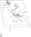
- Fig. 2 shows a section of the driver's cab, as seen through the door 8. It can be seen a part of the steering column 11 and arranged between the steering column 11 and a front edge of the bottom plate 6 center column 13, projecting from the two footrests 12 to the right and left in a position of use.
- the width of the center pillar 13 is adapted to that of the steering column 11, so that from the driver's perspective, the center pillar 13 is completely behind the steering column 11 supply. Only the footrests 12 Stand on both sides of the steering column 11, so that the driver can place his feet on it without obstruction by the steering column 11.
- the Fig. 3 shows in a view in the vehicle longitudinal direction of the combine a fitting part 14 with two pivotally mounted thereto footrests 12.
- the fitting part 14 is here a U-profile with the observer facing concave side, with a flat middle wall 15 and two from the edges of the central wall 15 in the direction of the viewer towards extending legs 16.
- the fitting 14 may be an integral part of the center column 13; Alternatively, the center column 13 or the steering column 11 may be provided on its side facing away from the driver's seat 10 with a vertically elongated rib on which the fitting 14 is attachable and to which it is screwed in different selectable heights to different heights of the footrests 12 on to realize the bottom plate 6.
- bearing parts 17 for the footrests 12 are attached on the legs 16, here in each case with the help of two screws.
- the bearing parts 17, like the fitting part 14, have a U-shaped cross-section with a center wall resting against one of the legs 16 and wings projecting at right angles from the middle wall and receiving two bolts with longitudinal axes 18, 19 in two bores each.
- the bolts can be secured in the holes of the bearing parts 17 each by pins.
- the longitudinal axis 18 of a bearing part 17 is in each case the pivot axis of one of the in Fig. 3
- the axis 19 is the pivot axis of a two-armed lever 20, the effect of which is based on Fig. 4 ff. will be explained in more detail later.
- One arm of the lever 20 is in Fig. 3 hidden inside the bearing part 17.
- a second arm of the lever 20 includes a leg 22 which extends from the journal 19 along the leg 16 of the fitting vertically downwards and is held by the leg 16 spread by a compression spring 23.
- a plate 24 is arranged which is extended in the vertical and in the vehicle longitudinal direction, so that the driver can comfortably hit it with a sideways movement of the foot and press against the center pillar 13, even without to be able to see him.
- the installation height of the fitting part 14 may be selected so that the plate 24 can be actuated by sideways pivoting of a foot resting on the base plate 6 with the heel.
- the plate 24 is replaced by a second leg 25, which extends from a lower end of the leg 22 sideways, away from the center column 13 extends.
- This leg 25 is preferably long enough to be visible from the perspective of the driver next to the steering column 11 or to be operable by extending a resting with the heel on the bottom plate 6 foot.
- levers 20 on the opposite side of the fitting part 14 could be mirror-inverted to the levers described above to be actuated in an analogous manner as described above from the right foot of the driver.
- both levers 20 are coupled to one another in order to rotate each other about their axis 19 when the left arm 21 is actuated in mirror image.
- a mechanism for coupling the two levers 20 may, for example, as in Fig. 2 shown hinged to the lower end of the legs 22 and be largely hidden in the center column 13.
- Fig. 4 shows a section perpendicular to the axes 18, 19 through the right bearing part 17 of Fig. 2 or 3 , a near-axis end of the right footrest 12 and the already mentioned, hidden in the bearing part 17 and here designated 26 arm of the lever 20th
- the footrest 12 is formed by a tube, for example with a cylindrical cross-section, in which case the axis 18 crosses the longitudinal axis of the tube and wall sections 27, 28 of the footrest 12 can be seen on either side of the axis 18. That in the Fig. 4 shown end of the footrest 12 is cut off obliquely, so that the wall portions 27, 28 in the position shown vary widely down and in particular facing away from the central column 13 wall portion 28 beyond the axis 18 and further than the opposite wall portion 27 extends down.
- a pivoting movement of the footrest 12 in a clockwise direction is blocked by a lower edge 29 of the wall section 27 being supported at the free end of the arm 26.
- the arm 26 can not yield to the pressure of the wall section 27, since a projection 30 of the lever 20 bearing against the center wall 31 of the bearing part 17 prevents it from pivoting counterclockwise.
- the pivoting movement ends when in the in Fig. 6 shown use position, the lower edge 29 of the wall portion 28 against a stop, here about the middle wall 31 of the bearing part 17, abuts.
- the driver can place his foot on the now upstanding wall portion 27, and the footrest 12 carries the weight of the foot.
- the length of the footrests 12 is dimensioned so that in the use position they protrude just far enough on both sides of the steering column 11 to allow comfortable placement of the feet on it, while at the same time avoiding restriction of the free view laterally from the feet resting thereon.
- the footrest 12 pivots upward in the direction of the waiting position.
- the lower edge 29 of the wall portion 28 initially strokes without touching on an upper side of the arm 26 along.
- the lower edge 29 finally abuts against a ramp 32 of the arm 26 and thus presses the arm 26 against the tension of the compression spring 23 downwards.
Landscapes
- Engineering & Computer Science (AREA)
- Transportation (AREA)
- Mechanical Engineering (AREA)
- Aviation & Aerospace Engineering (AREA)
- Harvester Elements (AREA)
- Body Structure For Vehicles (AREA)
Applications Claiming Priority (1)
| Application Number | Priority Date | Filing Date | Title |
|---|---|---|---|
| DE102018001267.1A DE102018001267A1 (de) | 2018-02-19 | 2018-02-19 | Fahrerkabine |
Publications (2)
| Publication Number | Publication Date |
|---|---|
| EP3530552A1 true EP3530552A1 (fr) | 2019-08-28 |
| EP3530552B1 EP3530552B1 (fr) | 2021-07-28 |
Family
ID=64664680
Family Applications (1)
| Application Number | Title | Priority Date | Filing Date |
|---|---|---|---|
| EP18211611.1A Active EP3530552B1 (fr) | 2018-02-19 | 2018-12-11 | Cabine de conducteur |
Country Status (2)
| Country | Link |
|---|---|
| EP (1) | EP3530552B1 (fr) |
| DE (1) | DE102018001267A1 (fr) |
Families Citing this family (1)
| Publication number | Priority date | Publication date | Assignee | Title |
|---|---|---|---|---|
| DE102024104934A1 (de) * | 2024-02-22 | 2025-08-28 | Liebherr-Werk Nenzing Gmbh | Kabinenelement, Kabine und Arbeitsmaschine |
Citations (3)
| Publication number | Priority date | Publication date | Assignee | Title |
|---|---|---|---|---|
| US20140049029A1 (en) * | 2012-08-16 | 2014-02-20 | Cnh America Llc | Steering column for a work vehicle with integral adjustable foot rests |
| DE102014204638A1 (de) * | 2014-03-13 | 2015-09-17 | Bayerische Motoren Werke Aktiengesellschaft | Modulares Fußrastenbaukastensystem |
| EP2873557B1 (fr) | 2012-07-12 | 2017-05-10 | Volvo Construction Equipment AB | Repose-pied pour cabine de commande d'engin de chantier |
-
2018
- 2018-02-19 DE DE102018001267.1A patent/DE102018001267A1/de not_active Withdrawn
- 2018-12-11 EP EP18211611.1A patent/EP3530552B1/fr active Active
Patent Citations (3)
| Publication number | Priority date | Publication date | Assignee | Title |
|---|---|---|---|---|
| EP2873557B1 (fr) | 2012-07-12 | 2017-05-10 | Volvo Construction Equipment AB | Repose-pied pour cabine de commande d'engin de chantier |
| US20140049029A1 (en) * | 2012-08-16 | 2014-02-20 | Cnh America Llc | Steering column for a work vehicle with integral adjustable foot rests |
| DE102014204638A1 (de) * | 2014-03-13 | 2015-09-17 | Bayerische Motoren Werke Aktiengesellschaft | Modulares Fußrastenbaukastensystem |
Also Published As
| Publication number | Publication date |
|---|---|
| DE102018001267A1 (de) | 2019-08-22 |
| EP3530552B1 (fr) | 2021-07-28 |
Similar Documents
| Publication | Publication Date | Title |
|---|---|---|
| EP2190396B1 (fr) | Fauteuil roulant releveur | |
| EP0215142B1 (fr) | Diviseur d'épis pour machines agricoles | |
| EP2263909B1 (fr) | Siège | |
| EP0054948A1 (fr) | Poste de conducteur | |
| DE102020134877B4 (de) | Höhenverstellbarer Steuerhebelträger für einen Nutzfahrzeugsitz | |
| EP0159562A2 (fr) | Fauteuil élévateur | |
| DE3227975A1 (de) | Selbstfahrender maehdrescher | |
| DE1283458B (de) | Sessel mit einer ein- und ausfahrbaren Beinstuetze | |
| EP1449711A2 (fr) | Siège pliable pour véhicules automobiles | |
| DE102017009248A1 (de) | Kleinfertiger, Bedienplattforrn für einen Kleinfertiger und Verfahren | |
| DE3711001A1 (de) | Ablage fuer kraftfahrzeuge, insbesondere im tunnelbereich eines lastkraftwagens zwischen fahrer- und beifahrersitz | |
| DE202007016357U1 (de) | Kraftfahrzeugsitz | |
| EP1291232B1 (fr) | Châssis de siège de véhicules automobiles avec un support de siège et bras avant de parallélogramme | |
| EP4482358B1 (fr) | Accessoire fonctionnel motorisé pour sommier de lit à sommier tapissier ou de lit plateforme, ou pour sommier à lattes | |
| DE3619944A1 (de) | Der rueckenlehne eines kraftfahrzeugsitzes zugeordnete armlehne | |
| EP1632152A2 (fr) | Meuble d'assise | |
| EP0518169A1 (fr) | Mécanisme de réglage de la hauteur d'un carter de coupe | |
| EP3530552B1 (fr) | Cabine de conducteur | |
| DE2001840A1 (de) | Fernseh- (TV-) und voellig zurueckkippbarer Lehnstuhl bzw. Sessel und Beschlagteile fuer seinen Gelenk- und Kippmechanismus | |
| DE4113828C2 (de) | Fahrzeug zum Mähen | |
| DE2117665A1 (de) | Selbstfahrende Mähvorrichtung | |
| DE2049282C3 (de) | Patientenstuhl | |
| EP0372232B1 (fr) | Chaise, notamment chaise de travail ou chaise de bureau | |
| DE2028612A1 (de) | Aufhangung für einen Fahrzeugsitz | |
| DE69803513T2 (de) | Mähdrescherleiter mit Schwenkgelenkzapfen |
Legal Events
| Date | Code | Title | Description |
|---|---|---|---|
| PUAI | Public reference made under article 153(3) epc to a published international application that has entered the european phase |
Free format text: ORIGINAL CODE: 0009012 |
|
| STAA | Information on the status of an ep patent application or granted ep patent |
Free format text: STATUS: THE APPLICATION HAS BEEN PUBLISHED |
|
| AK | Designated contracting states |
Kind code of ref document: A1 Designated state(s): AL AT BE BG CH CY CZ DE DK EE ES FI FR GB GR HR HU IE IS IT LI LT LU LV MC MK MT NL NO PL PT RO RS SE SI SK SM TR |
|
| AX | Request for extension of the european patent |
Extension state: BA ME |
|
| STAA | Information on the status of an ep patent application or granted ep patent |
Free format text: STATUS: REQUEST FOR EXAMINATION WAS MADE |
|
| 17P | Request for examination filed |
Effective date: 20200228 |
|
| RBV | Designated contracting states (corrected) |
Designated state(s): AL AT BE BG CH CY CZ DE DK EE ES FI FR GB GR HR HU IE IS IT LI LT LU LV MC MK MT NL NO PL PT RO RS SE SI SK SM TR |
|
| GRAP | Despatch of communication of intention to grant a patent |
Free format text: ORIGINAL CODE: EPIDOSNIGR1 |
|
| STAA | Information on the status of an ep patent application or granted ep patent |
Free format text: STATUS: GRANT OF PATENT IS INTENDED |
|
| RIC1 | Information provided on ipc code assigned before grant |
Ipc: B62D 33/06 20060101AFI20210205BHEP Ipc: B60N 3/06 20060101ALI20210205BHEP Ipc: B60N 2/24 20060101ALI20210205BHEP Ipc: B60N 2/38 20060101ALI20210205BHEP |
|
| INTG | Intention to grant announced |
Effective date: 20210309 |
|
| GRAS | Grant fee paid |
Free format text: ORIGINAL CODE: EPIDOSNIGR3 |
|
| GRAA | (expected) grant |
Free format text: ORIGINAL CODE: 0009210 |
|
| STAA | Information on the status of an ep patent application or granted ep patent |
Free format text: STATUS: THE PATENT HAS BEEN GRANTED |
|
| AK | Designated contracting states |
Kind code of ref document: B1 Designated state(s): AL AT BE BG CH CY CZ DE DK EE ES FI FR GB GR HR HU IE IS IT LI LT LU LV MC MK MT NL NO PL PT RO RS SE SI SK SM TR |
|
| REG | Reference to a national code |
Ref country code: GB Ref legal event code: FG4D Free format text: NOT ENGLISH |
|
| REG | Reference to a national code |
Ref country code: CH Ref legal event code: EP |
|
| REG | Reference to a national code |
Ref country code: AT Ref legal event code: REF Ref document number: 1414518 Country of ref document: AT Kind code of ref document: T Effective date: 20210815 |
|
| REG | Reference to a national code |
Ref country code: IE Ref legal event code: FG4D Free format text: LANGUAGE OF EP DOCUMENT: GERMAN |
|
| REG | Reference to a national code |
Ref country code: DE Ref legal event code: R096 Ref document number: 502018006296 Country of ref document: DE |
|
| REG | Reference to a national code |
Ref country code: LT Ref legal event code: MG9D |
|
| REG | Reference to a national code |
Ref country code: NL Ref legal event code: MP Effective date: 20210728 |
|
| PG25 | Lapsed in a contracting state [announced via postgrant information from national office to epo] |
Ref country code: RS Free format text: LAPSE BECAUSE OF FAILURE TO SUBMIT A TRANSLATION OF THE DESCRIPTION OR TO PAY THE FEE WITHIN THE PRESCRIBED TIME-LIMIT Effective date: 20210728 Ref country code: SE Free format text: LAPSE BECAUSE OF FAILURE TO SUBMIT A TRANSLATION OF THE DESCRIPTION OR TO PAY THE FEE WITHIN THE PRESCRIBED TIME-LIMIT Effective date: 20210728 Ref country code: HR Free format text: LAPSE BECAUSE OF FAILURE TO SUBMIT A TRANSLATION OF THE DESCRIPTION OR TO PAY THE FEE WITHIN THE PRESCRIBED TIME-LIMIT Effective date: 20210728 Ref country code: ES Free format text: LAPSE BECAUSE OF FAILURE TO SUBMIT A TRANSLATION OF THE DESCRIPTION OR TO PAY THE FEE WITHIN THE PRESCRIBED TIME-LIMIT Effective date: 20210728 Ref country code: FI Free format text: LAPSE BECAUSE OF FAILURE TO SUBMIT A TRANSLATION OF THE DESCRIPTION OR TO PAY THE FEE WITHIN THE PRESCRIBED TIME-LIMIT Effective date: 20210728 Ref country code: NO Free format text: LAPSE BECAUSE OF FAILURE TO SUBMIT A TRANSLATION OF THE DESCRIPTION OR TO PAY THE FEE WITHIN THE PRESCRIBED TIME-LIMIT Effective date: 20211028 Ref country code: PT Free format text: LAPSE BECAUSE OF FAILURE TO SUBMIT A TRANSLATION OF THE DESCRIPTION OR TO PAY THE FEE WITHIN THE PRESCRIBED TIME-LIMIT Effective date: 20211129 Ref country code: NL Free format text: LAPSE BECAUSE OF FAILURE TO SUBMIT A TRANSLATION OF THE DESCRIPTION OR TO PAY THE FEE WITHIN THE PRESCRIBED TIME-LIMIT Effective date: 20210728 Ref country code: LT Free format text: LAPSE BECAUSE OF FAILURE TO SUBMIT A TRANSLATION OF THE DESCRIPTION OR TO PAY THE FEE WITHIN THE PRESCRIBED TIME-LIMIT Effective date: 20210728 Ref country code: BG Free format text: LAPSE BECAUSE OF FAILURE TO SUBMIT A TRANSLATION OF THE DESCRIPTION OR TO PAY THE FEE WITHIN THE PRESCRIBED TIME-LIMIT Effective date: 20211028 |
|
| PG25 | Lapsed in a contracting state [announced via postgrant information from national office to epo] |
Ref country code: PL Free format text: LAPSE BECAUSE OF FAILURE TO SUBMIT A TRANSLATION OF THE DESCRIPTION OR TO PAY THE FEE WITHIN THE PRESCRIBED TIME-LIMIT Effective date: 20210728 Ref country code: LV Free format text: LAPSE BECAUSE OF FAILURE TO SUBMIT A TRANSLATION OF THE DESCRIPTION OR TO PAY THE FEE WITHIN THE PRESCRIBED TIME-LIMIT Effective date: 20210728 Ref country code: GR Free format text: LAPSE BECAUSE OF FAILURE TO SUBMIT A TRANSLATION OF THE DESCRIPTION OR TO PAY THE FEE WITHIN THE PRESCRIBED TIME-LIMIT Effective date: 20211029 |
|
| PG25 | Lapsed in a contracting state [announced via postgrant information from national office to epo] |
Ref country code: DK Free format text: LAPSE BECAUSE OF FAILURE TO SUBMIT A TRANSLATION OF THE DESCRIPTION OR TO PAY THE FEE WITHIN THE PRESCRIBED TIME-LIMIT Effective date: 20210728 |
|
| REG | Reference to a national code |
Ref country code: DE Ref legal event code: R097 Ref document number: 502018006296 Country of ref document: DE |
|
| PG25 | Lapsed in a contracting state [announced via postgrant information from national office to epo] |
Ref country code: SM Free format text: LAPSE BECAUSE OF FAILURE TO SUBMIT A TRANSLATION OF THE DESCRIPTION OR TO PAY THE FEE WITHIN THE PRESCRIBED TIME-LIMIT Effective date: 20210728 Ref country code: SK Free format text: LAPSE BECAUSE OF FAILURE TO SUBMIT A TRANSLATION OF THE DESCRIPTION OR TO PAY THE FEE WITHIN THE PRESCRIBED TIME-LIMIT Effective date: 20210728 Ref country code: RO Free format text: LAPSE BECAUSE OF FAILURE TO SUBMIT A TRANSLATION OF THE DESCRIPTION OR TO PAY THE FEE WITHIN THE PRESCRIBED TIME-LIMIT Effective date: 20210728 Ref country code: EE Free format text: LAPSE BECAUSE OF FAILURE TO SUBMIT A TRANSLATION OF THE DESCRIPTION OR TO PAY THE FEE WITHIN THE PRESCRIBED TIME-LIMIT Effective date: 20210728 Ref country code: CZ Free format text: LAPSE BECAUSE OF FAILURE TO SUBMIT A TRANSLATION OF THE DESCRIPTION OR TO PAY THE FEE WITHIN THE PRESCRIBED TIME-LIMIT Effective date: 20210728 Ref country code: AL Free format text: LAPSE BECAUSE OF FAILURE TO SUBMIT A TRANSLATION OF THE DESCRIPTION OR TO PAY THE FEE WITHIN THE PRESCRIBED TIME-LIMIT Effective date: 20210728 |
|
| PLBE | No opposition filed within time limit |
Free format text: ORIGINAL CODE: 0009261 |
|
| STAA | Information on the status of an ep patent application or granted ep patent |
Free format text: STATUS: NO OPPOSITION FILED WITHIN TIME LIMIT |
|
| 26N | No opposition filed |
Effective date: 20220429 |
|
| PG25 | Lapsed in a contracting state [announced via postgrant information from national office to epo] |
Ref country code: MC Free format text: LAPSE BECAUSE OF FAILURE TO SUBMIT A TRANSLATION OF THE DESCRIPTION OR TO PAY THE FEE WITHIN THE PRESCRIBED TIME-LIMIT Effective date: 20210728 Ref country code: IT Free format text: LAPSE BECAUSE OF FAILURE TO SUBMIT A TRANSLATION OF THE DESCRIPTION OR TO PAY THE FEE WITHIN THE PRESCRIBED TIME-LIMIT Effective date: 20210728 |
|
| REG | Reference to a national code |
Ref country code: CH Ref legal event code: PL |
|
| PG25 | Lapsed in a contracting state [announced via postgrant information from national office to epo] |
Ref country code: LU Free format text: LAPSE BECAUSE OF NON-PAYMENT OF DUE FEES Effective date: 20211211 Ref country code: IE Free format text: LAPSE BECAUSE OF NON-PAYMENT OF DUE FEES Effective date: 20211211 |
|
| PG25 | Lapsed in a contracting state [announced via postgrant information from national office to epo] |
Ref country code: FR Free format text: LAPSE BECAUSE OF NON-PAYMENT OF DUE FEES Effective date: 20211231 |
|
| PG25 | Lapsed in a contracting state [announced via postgrant information from national office to epo] |
Ref country code: LI Free format text: LAPSE BECAUSE OF NON-PAYMENT OF DUE FEES Effective date: 20211231 Ref country code: CH Free format text: LAPSE BECAUSE OF NON-PAYMENT OF DUE FEES Effective date: 20211231 |
|
| P01 | Opt-out of the competence of the unified patent court (upc) registered |
Effective date: 20230516 |
|
| PG25 | Lapsed in a contracting state [announced via postgrant information from national office to epo] |
Ref country code: CY Free format text: LAPSE BECAUSE OF FAILURE TO SUBMIT A TRANSLATION OF THE DESCRIPTION OR TO PAY THE FEE WITHIN THE PRESCRIBED TIME-LIMIT Effective date: 20210728 |
|
| PG25 | Lapsed in a contracting state [announced via postgrant information from national office to epo] |
Ref country code: HU Free format text: LAPSE BECAUSE OF FAILURE TO SUBMIT A TRANSLATION OF THE DESCRIPTION OR TO PAY THE FEE WITHIN THE PRESCRIBED TIME-LIMIT; INVALID AB INITIO Effective date: 20181211 |
|
| GBPC | Gb: european patent ceased through non-payment of renewal fee |
Effective date: 20221211 |
|
| PG25 | Lapsed in a contracting state [announced via postgrant information from national office to epo] |
Ref country code: GB Free format text: LAPSE BECAUSE OF NON-PAYMENT OF DUE FEES Effective date: 20221211 |
|
| PG25 | Lapsed in a contracting state [announced via postgrant information from national office to epo] |
Ref country code: MK Free format text: LAPSE BECAUSE OF FAILURE TO SUBMIT A TRANSLATION OF THE DESCRIPTION OR TO PAY THE FEE WITHIN THE PRESCRIBED TIME-LIMIT Effective date: 20210728 |
|
| PG25 | Lapsed in a contracting state [announced via postgrant information from national office to epo] |
Ref country code: TR Free format text: LAPSE BECAUSE OF FAILURE TO SUBMIT A TRANSLATION OF THE DESCRIPTION OR TO PAY THE FEE WITHIN THE PRESCRIBED TIME-LIMIT Effective date: 20210728 |
|
| PG25 | Lapsed in a contracting state [announced via postgrant information from national office to epo] |
Ref country code: MT Free format text: LAPSE BECAUSE OF FAILURE TO SUBMIT A TRANSLATION OF THE DESCRIPTION OR TO PAY THE FEE WITHIN THE PRESCRIBED TIME-LIMIT Effective date: 20210728 |
|
| REG | Reference to a national code |
Ref country code: AT Ref legal event code: MM01 Ref document number: 1414518 Country of ref document: AT Kind code of ref document: T Effective date: 20231211 |
|
| PG25 | Lapsed in a contracting state [announced via postgrant information from national office to epo] |
Ref country code: AT Free format text: LAPSE BECAUSE OF NON-PAYMENT OF DUE FEES Effective date: 20231211 |
|
| PGFP | Annual fee paid to national office [announced via postgrant information from national office to epo] |
Ref country code: DE Payment date: 20251211 Year of fee payment: 8 |
|
| PGFP | Annual fee paid to national office [announced via postgrant information from national office to epo] |
Ref country code: BE Payment date: 20251219 Year of fee payment: 8 |
|
| PGFP | Annual fee paid to national office [announced via postgrant information from national office to epo] |
Ref country code: AT Payment date: 20260410 Year of fee payment: 5 |