EP3530601A1 - Procédés et systèmes de fonctionnement d'un appareil de manipulation de matériau - Google Patents
Procédés et systèmes de fonctionnement d'un appareil de manipulation de matériau Download PDFInfo
- Publication number
- EP3530601A1 EP3530601A1 EP19157600.8A EP19157600A EP3530601A1 EP 3530601 A1 EP3530601 A1 EP 3530601A1 EP 19157600 A EP19157600 A EP 19157600A EP 3530601 A1 EP3530601 A1 EP 3530601A1
- Authority
- EP
- European Patent Office
- Prior art keywords
- image
- handling apparatus
- material handling
- processor
- regions
- Prior art date
- Legal status (The legal status is an assumption and is not a legal conclusion. Google has not performed a legal analysis and makes no representation as to the accuracy of the status listed.)
- Withdrawn
Links
Images




Classifications
-
- B—PERFORMING OPERATIONS; TRANSPORTING
- B65—CONVEYING; PACKING; STORING; HANDLING THIN OR FILAMENTARY MATERIAL
- B65G—TRANSPORT OR STORAGE DEVICES, e.g. CONVEYORS FOR LOADING OR TIPPING, SHOP CONVEYOR SYSTEMS OR PNEUMATIC TUBE CONVEYORS
- B65G67/00—Loading or unloading vehicles
- B65G67/02—Loading or unloading land vehicles
- B65G67/04—Loading land vehicles
-
- B—PERFORMING OPERATIONS; TRANSPORTING
- B25—HAND TOOLS; PORTABLE POWER-DRIVEN TOOLS; MANIPULATORS
- B25J—MANIPULATORS; CHAMBERS PROVIDED WITH MANIPULATION DEVICES
- B25J9/00—Program-controlled manipulators
- B25J9/16—Program controls
- B25J9/1674—Program controls characterised by safety, monitoring, diagnostic
- B25J9/1676—Avoiding collision or forbidden zones
-
- B—PERFORMING OPERATIONS; TRANSPORTING
- B65—CONVEYING; PACKING; STORING; HANDLING THIN OR FILAMENTARY MATERIAL
- B65G—TRANSPORT OR STORAGE DEVICES, e.g. CONVEYORS FOR LOADING OR TIPPING, SHOP CONVEYOR SYSTEMS OR PNEUMATIC TUBE CONVEYORS
- B65G1/00—Storing articles, individually or in orderly arrangement, in warehouses or magazines
- B65G1/02—Storage devices
- B65G1/04—Storage devices mechanical
- B65G1/0407—Storage devices mechanical using stacker cranes
-
- B—PERFORMING OPERATIONS; TRANSPORTING
- B25—HAND TOOLS; PORTABLE POWER-DRIVEN TOOLS; MANIPULATORS
- B25J—MANIPULATORS; CHAMBERS PROVIDED WITH MANIPULATION DEVICES
- B25J13/00—Controls for manipulators
- B25J13/08—Controls for manipulators by means of sensing devices, e.g. viewing or touching devices
- B25J13/088—Controls for manipulators by means of sensing devices, e.g. viewing or touching devices with position, velocity or acceleration sensors
- B25J13/089—Determining the position of the robot with reference to its environment
-
- B—PERFORMING OPERATIONS; TRANSPORTING
- B25—HAND TOOLS; PORTABLE POWER-DRIVEN TOOLS; MANIPULATORS
- B25J—MANIPULATORS; CHAMBERS PROVIDED WITH MANIPULATION DEVICES
- B25J19/00—Accessories fitted to manipulators, e.g. for monitoring, for viewing; Safety devices combined with or specially adapted for use in connection with manipulators
- B25J19/02—Sensing devices
- B25J19/021—Optical sensing devices
-
- B—PERFORMING OPERATIONS; TRANSPORTING
- B25—HAND TOOLS; PORTABLE POWER-DRIVEN TOOLS; MANIPULATORS
- B25J—MANIPULATORS; CHAMBERS PROVIDED WITH MANIPULATION DEVICES
- B25J5/00—Manipulators mounted on wheels or on carriages
-
- B—PERFORMING OPERATIONS; TRANSPORTING
- B25—HAND TOOLS; PORTABLE POWER-DRIVEN TOOLS; MANIPULATORS
- B25J—MANIPULATORS; CHAMBERS PROVIDED WITH MANIPULATION DEVICES
- B25J9/00—Program-controlled manipulators
- B25J9/16—Program controls
- B25J9/1694—Program controls characterised by use of sensors other than normal servo-feedback from position, speed or acceleration sensors, perception control, multi-sensor controlled systems, sensor fusion
- B25J9/1697—Vision controlled systems
-
- B—PERFORMING OPERATIONS; TRANSPORTING
- B65—CONVEYING; PACKING; STORING; HANDLING THIN OR FILAMENTARY MATERIAL
- B65G—TRANSPORT OR STORAGE DEVICES, e.g. CONVEYORS FOR LOADING OR TIPPING, SHOP CONVEYOR SYSTEMS OR PNEUMATIC TUBE CONVEYORS
- B65G1/00—Storing articles, individually or in orderly arrangement, in warehouses or magazines
- B65G1/02—Storage devices
- B65G1/04—Storage devices mechanical
- B65G1/0485—Check-in, check-out devices
-
- B—PERFORMING OPERATIONS; TRANSPORTING
- B65—CONVEYING; PACKING; STORING; HANDLING THIN OR FILAMENTARY MATERIAL
- B65G—TRANSPORT OR STORAGE DEVICES, e.g. CONVEYORS FOR LOADING OR TIPPING, SHOP CONVEYOR SYSTEMS OR PNEUMATIC TUBE CONVEYORS
- B65G1/00—Storing articles, individually or in orderly arrangement, in warehouses or magazines
- B65G1/02—Storage devices
- B65G1/04—Storage devices mechanical
- B65G1/137—Storage devices mechanical with arrangements or automatic control means for selecting which articles are to be removed
- B65G1/1373—Storage devices mechanical with arrangements or automatic control means for selecting which articles are to be removed for fulfilling orders in warehouses
- B65G1/1378—Storage devices mechanical with arrangements or automatic control means for selecting which articles are to be removed for fulfilling orders in warehouses the orders being assembled on fixed commissioning areas remote from the storage areas
-
- B—PERFORMING OPERATIONS; TRANSPORTING
- B65—CONVEYING; PACKING; STORING; HANDLING THIN OR FILAMENTARY MATERIAL
- B65G—TRANSPORT OR STORAGE DEVICES, e.g. CONVEYORS FOR LOADING OR TIPPING, SHOP CONVEYOR SYSTEMS OR PNEUMATIC TUBE CONVEYORS
- B65G65/00—Loading or unloading
- B65G65/005—Control arrangements
-
- B—PERFORMING OPERATIONS; TRANSPORTING
- B65—CONVEYING; PACKING; STORING; HANDLING THIN OR FILAMENTARY MATERIAL
- B65G—TRANSPORT OR STORAGE DEVICES, e.g. CONVEYORS FOR LOADING OR TIPPING, SHOP CONVEYOR SYSTEMS OR PNEUMATIC TUBE CONVEYORS
- B65G67/00—Loading or unloading vehicles
- B65G67/02—Loading or unloading land vehicles
-
- B—PERFORMING OPERATIONS; TRANSPORTING
- B65—CONVEYING; PACKING; STORING; HANDLING THIN OR FILAMENTARY MATERIAL
- B65G—TRANSPORT OR STORAGE DEVICES, e.g. CONVEYORS FOR LOADING OR TIPPING, SHOP CONVEYOR SYSTEMS OR PNEUMATIC TUBE CONVEYORS
- B65G67/00—Loading or unloading vehicles
- B65G67/02—Loading or unloading land vehicles
- B65G67/24—Unloading land vehicles
-
- B—PERFORMING OPERATIONS; TRANSPORTING
- B65—CONVEYING; PACKING; STORING; HANDLING THIN OR FILAMENTARY MATERIAL
- B65G—TRANSPORT OR STORAGE DEVICES, e.g. CONVEYORS FOR LOADING OR TIPPING, SHOP CONVEYOR SYSTEMS OR PNEUMATIC TUBE CONVEYORS
- B65G69/00—Auxiliary measures taken, or devices used, in connection with loading or unloading
- B65G69/28—Loading ramps; Loading docks
- B65G69/287—Constructional features of deck or surround
- B65G69/2876—Safety or protection means, e.g. skirts
- B65G69/2882—Safety or protection means, e.g. skirts operated by detectors or sensors
-
- G—PHYSICS
- G05—CONTROLLING; REGULATING
- G05D—SYSTEMS FOR CONTROLLING OR REGULATING NON-ELECTRIC VARIABLES
- G05D1/00—Control of position, course, altitude or attitude of land, water, air or space vehicles, e.g. using automatic pilots
- G05D1/02—Control of position or course in two dimensions
- G05D1/021—Control of position or course in two dimensions specially adapted to land vehicles
- G05D1/0231—Control of position or course in two dimensions specially adapted to land vehicles using optical position detecting means
- G05D1/0238—Control of position or course in two dimensions specially adapted to land vehicles using optical position detecting means using obstacle or wall sensors
- G05D1/024—Control of position or course in two dimensions specially adapted to land vehicles using optical position detecting means using obstacle or wall sensors in combination with a laser
-
- G—PHYSICS
- G05—CONTROLLING; REGULATING
- G05D—SYSTEMS FOR CONTROLLING OR REGULATING NON-ELECTRIC VARIABLES
- G05D1/00—Control of position, course, altitude or attitude of land, water, air or space vehicles, e.g. using automatic pilots
- G05D1/02—Control of position or course in two dimensions
- G05D1/021—Control of position or course in two dimensions specially adapted to land vehicles
- G05D1/0231—Control of position or course in two dimensions specially adapted to land vehicles using optical position detecting means
- G05D1/0246—Control of position or course in two dimensions specially adapted to land vehicles using optical position detecting means using a video camera in combination with image processing means
- G05D1/0251—Control of position or course in two dimensions specially adapted to land vehicles using optical position detecting means using a video camera in combination with image processing means extracting 3D information from a plurality of images taken from different locations, e.g. stereo vision
-
- B—PERFORMING OPERATIONS; TRANSPORTING
- B65—CONVEYING; PACKING; STORING; HANDLING THIN OR FILAMENTARY MATERIAL
- B65G—TRANSPORT OR STORAGE DEVICES, e.g. CONVEYORS FOR LOADING OR TIPPING, SHOP CONVEYOR SYSTEMS OR PNEUMATIC TUBE CONVEYORS
- B65G2203/00—Indexing code relating to control or detection of the articles or the load carriers during conveying
- B65G2203/04—Detection means
- B65G2203/041—Camera
-
- B—PERFORMING OPERATIONS; TRANSPORTING
- B65—CONVEYING; PACKING; STORING; HANDLING THIN OR FILAMENTARY MATERIAL
- B65G—TRANSPORT OR STORAGE DEVICES, e.g. CONVEYORS FOR LOADING OR TIPPING, SHOP CONVEYOR SYSTEMS OR PNEUMATIC TUBE CONVEYORS
- B65G2209/00—Indexing codes relating to order picking devices in General
- B65G2209/04—Indication location means
Definitions
- the present disclosure relates in general to a material handling system. More specifically, the present disclosure relates to methods and systems for operating a material handling apparatus in the material handling system.
- various operations may be performed to manage transportation and storage of articles.
- such operations may be performed either manually by workers, or by machines.
- the machines may be utilized to load and/or unload the articles on and/or from a container. Further, the machines may transport the articles to a storage location in the warehouse.
- Such machines may operate in an autonomous mode, where the machines may perform the aforementioned operations without manual intervention.
- Some examples of the machines may include, but are not limited to, a conveyor belt, a forklift machine, a robotic carton unloader, and/or the like.
- the machine may perform one or more operations such as, but not limited to, identifying a location of the articles, determining a navigation path to the location of the articles, and traversing along the determined navigation path.
- the determined navigation path, to the identified articles may not be clear for traversal of the machine due to presence of one or more obstacles on the navigation path.
- the one or more obstacles include, but are not limited to, stray articles, humans, and/or the like. Traversing the machine along such a path may not be desirable.
- the method may include defining, by a processor, a first area in a Three-Dimensional (3D) image of a worksite, including a docked container, based on an identification of one or more sections of the docked container in the 3-D image.
- the first area is exterior to the docked container.
- the method may include identifying, by the processor, one or more regions in the first area representative of one or more objects positioned exterior to the docked container.
- the method may include operating, by the processor, a material handling apparatus based on one or more characteristics associated with the one or more objects.
- the material handling apparatus may include an article manipulator. Further, the material handling apparatus may include an image-capturing device positioned on the material handling apparatus. Additionally, the material handling apparatus may include a processor communicatively coupled to the article manipulator and the image-capturing device. The processor is adapted to instruct the image-capturing device to capture a Three-Dimensional (3-D) image of a worksite comprising a docked container. Further, the processor is adapted to define a first area in the 3-D image of a worksite, comprising a docked container, based on an identification of one or more sections of the docked container in the 3-D image, wherein the first area is exterior to the docked container. Furthermore, the processor is adapted to identify one or more regions in the first area representative of one or more objects positioned exterior to the docked container. Additionally, the processor is adapted to operate the material handling apparatus based on one or more characteristics associated with the one or more objects.
- the control system may include an image-capturing device. Further, the control system may include a processor communicatively coupled to the image-capturing device. The processor is adapted to instruct the image-capturing device to capture a 3-D image of a worksite comprising a docked container. Further, the processor is adapted to define a first area in a 3-D image based on an identification of one or more sections of the docked container in the 3-D image, wherein the first area represents an exterior to the docked container. Additionally, the processor is adapted to identify one or more regions in the first area representative of one or more objects positioned exterior to the docked container. Furthermore, the processor is adapted to operate the material handling apparatus based on one or more characteristics associated with the one or more objects.
- a material handling system may include one or more machines that may operate in tandem to perform predetermined operations in a worksite (for example, a warehouse).
- the material handling system may include a material handling apparatus that may be adapted to unload articles from a location in the worksite and transfer the unloaded articles to another location in the worksite.
- the material handling apparatus may pick the articles from a docked container and may place the picked articles on a conveyor for transportation purposes.
- the material handling apparatus may receive a Three-Dimensional (3-D) image of the worksite.
- the 3-D image is captured in such a manner that the 3-D image includes an image of the docked container.
- the material handling apparatus may be adapted to identify one or more sections of the docked container.
- the one or more sections of the docked container may include, but are not limited to, one or more sidewalls of the docked container, a floor of the docked container, a ceiling of the docked container, and one or more doors of the docked container.
- the material handling apparatus may be adapted to define a first area in the 3-D image that defines an exterior of the docked container. Subsequently, the material handling apparatus may be adapted to determine a first navigation path, within the first area, and ingress to the docked container. Further, the material handling apparatus may traverse along the first navigation path in order to traverse inside of the docked container. Additionally, the material handling apparatus may be adapted to identify one or more objects in the first area. The one or more objects in the first area may correspond to the objects that are placed and/or positioned exterior to the docked container. Further, the material handling apparatus may be adapted to determine whether the one or more identified objects correspond to articles.
- the material handling apparatus may be adapted to halt the operation until the articles in the first area are removed. In an alternate exemplary embodiment, the material handling apparatus may be adapted to remove the articles from the first area and/or reposition the articles to another location outside of the first area.
- the material handling apparatus may be adapted to identify one or more transitional components in the first area.
- the one or more transitional components may include, but are not limited to, a ramp and a dock leveler.
- the material handling apparatus may be adapted to determine an orientation of the one or more transitional components with respect to a ground surface.
- the material handling apparatus may be disposed on the ground surface when the 3D image is captured and/or received by the material handling apparatus. Accordingly, the material handling apparatus is operated based on the orientation of the one or more transitional components.
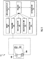
- FIG. 1 illustrates a schematic representation of a worksite 100, in accordance with one or more exemplary embodiments.
- the worksite 100 may correspond to a predefined area where an operation such as loading and/or unloading of articles and storage of the articles may be facilitated.
- Some examples of the worksite 100 may include, but are not limited to, a warehouse, a retail outlet, and/or the like.
- the worksite 100 may include a container 102, one or more transitional components 104, a material handling apparatus 106, one or more image-capturing devices 108a, and 108b and a remote control center 110.
- the material handling apparatus 106 may further include an article manipulator 112, a plurality of traction devices 114, and a control system 116.
- the one or more image-capturing devices 108a, and 108b, the material handling apparatus 106, and the remote control center 110 may be communicatively coupled with each other through a network 118.
- the container 102 may correspond to a storage unit that is adapted to store a plurality of articles 120.
- the container 102 may be placed on a vehicle (not shown) such as a truck for transportation of the plurality of articles 120.
- the container 102 may include one or more sections such as one or more doors 122, a floor 124, a ceiling 126, and one or more sidewalls 128.
- the container 102 may be docked in the worksite 100 at a first predetermined location (depicted by 138) in the worksite 100.
- the one or more transitional components 104 may be positioned in such a manner that the one or more transitional components 104 couple with the floor 124 of the docked container 102 and a ground surface 132 of the worksite 100.
- the one or more transitional components 104 may correspond to objects that are adapted to couple the ground surface 132 of the worksite 100 with the floor 124 of the container 102, such that a traversal path ingress and egress to and from the container 102 is formed.
- an orientation of the one or more transitional components 104, with respect to the ground surface 132 of the worksite 100 may be adjusted in accordance with an orientation of the floor 124 of the container 102 with respect to the ground surface 132.
- a pitch of the one or more transitional components 104 may be adjusted such that the one or more transitional components 104 couples to both the floor 124 and the ground surface 132.
- the one or more transitional components 104 may be coupled to one or more actuators (not shown) such as hydraulic cylinders, motors, and/or the like.
- the one or more actuators may be actuated to allow the modification of the orientation of the one or more transitional components 104.
- Some examples of the one or more transitional components 104 may include, but are not limited to, a ramp 134, and a dock leveler 136.
- the ramp 134 may correspond to an inclination surface that may couple to surfaces at two different elevation levels.
- the ramp 134 may be coupled to the ground surface 132 and the floor 124 of the docked container 102.
- the dock leveler 136 may correspond to a metal plate that may be coupled to a first end of the ramp 134 in such a manner that the dock leveler 136 may couple the floor 124 of the docked container 102 and the ramp 134.
- the material handling apparatus 106 may correspond to a machine that is adapted to load and unload the articles to and from the docked container 102.
- the material handling apparatus 106 may include the control system 116 that is adapted to control the operation of one or more components of the material handling apparatus 106.
- the control system 116 may be adapted to control the operation of the article manipulator 112, and the plurality of traction devices 114.
- the control system 116 may be further adapted to control the operation of the image-capturing device 108b.
- control system 116 may be adapted to instruct the image-capturing device 108b to capture a 3-D image of the worksite 100 such that the 3-D image includes an image of the docked container 102. Thereafter, the control system 116 may be adapted to control the operation of the material handling apparatus 106 based on the captured 3-D image. Controlling the operation of the material handling apparatus 106 has been described later in conjunction with FIG. 3 .
- the material handling apparatus 106 may include, but are not limited to, a robotic carton unloader, a forklift machine, and/or any other machine that is adapted to load and unload articles to and from the docked container 102.
- the one or more image-capturing devices 108a and 108b may be adapted to capture the 3-D image of the worksite 100.
- the one or more image-capturing devices 108a and 108b may be positioned at predefined locations in the worksite 100.
- the image-capturing device 108a may be positioned on and/or suspended from a ceiling (not shown) of the worksite 100.
- the image-capturing device 108b may be positioned on the material handling apparatus 106. More particularly, the image-capturing device 108b may be positioned on the article manipulator 112 of the material handling apparatus 106.
- the image-capturing device 108b has been considered to capture the 3-D image of the worksite 100.
- the scope of the disclosure should not limited to capturing the 3-D image using the image-capturing device 108b. It may be contemplated that the image-capturing device 108a can also be utilized to capture the 3-D image.
- the one or more image-capturing devices 108a and 108b may include an image sensor that is adapted to capture the 3-D image.
- the 3-D image captured by the one or more image-capturing devices 108a and 108b may correspond to a 3-D point cloud, where a plurality of points (e.g., 3-D points defined by 3-D coordinates) is utilized to represent an object in the 3-D image.
- the plurality of points may be utilized to represent a docked container 102 in the 3-D image.
- Each point in the plurality of points may include information pertaining to a coordinate of the point and an orientation of the point, with respect to the material handling apparatus 106.
- the orientation of a point in the 3-D point cloud may correspond to a pitch, a yaw, and a roll of the point.
- the coordinate of the point in the 3-D point cloud may be deterministic of a position of the point in the 3-D image. Further, the coordinate of the point may be deterministic of a depth of the point with respect to the image-capturing device 108b.
- the one or more image-capturing devices 108a and 108b may be adapted to transmit the captured 3-D image to the control system 116 of the material handling apparatus 106.
- the one or more image-capturing devices 108a and 108b may include, but are not limited to, a camera, a stereo camera, a 2-D Lidar, a 3-D Lidar, and/or the like.
- the remote control center 110 may include one or more computing devices that may enable a user or administrator to monitor various operations being performed in the worksite 100.
- the remote control center 110 may be communicatively coupled to each of the one or more image-capturing devices 108a and 108b, and the material handling apparatus 106 through the network 118.
- the remote control center 110 may include an application server 130 that is communicatively coupled to the one or more image-capturing devices 108a, and 108b, and the material handling apparatus 106 through the network 118.
- the application server 130 may be adapted to monitor and control the operations of the one or more image-capturing devices 108a and 108b, and the material handling apparatus 106.
- the functionalities of the control system 116 of the material handling apparatus 106 may be implemented in the application server 130.
- the application server 130 may be adapted to remotely control the operations of the material handling apparatus 106. Further, in such a scenario, the need for the control system 116 in the material handling apparatus 106 may not be required.
- Some examples of the application server 130 may include, but are not limited to, a JBossTM application server, JavaTM Application server, Apache TomcatTM server, IBM WebsphereTM, and/or the like.
- the network 118 may correspond to a medium through which content and messages flow between various devices and/or machines in the worksite 100 (e.g., the one or more image-capturing devices 108a and 108b, and material handling apparatus 106).
- Examples of the network 118 may include, but are not limited to, a Wireless Fidelity (Wi-Fi) network, a Wireless Area Network (WAN), a Local Area Network (LAN), or a Metropolitan Area Network (MAN).
- Various devices and/or machines in the worksite 100 can connect to the network 118 in accordance with various wired and wireless communication protocols such as, for example, Transmission Control Protocol and Internet Protocol (TCP/IP), User Datagram Protocol (UDP), and 2G, 3G, or 4G communication protocols.
- TCP/IP Transmission Control Protocol and Internet Protocol
- UDP User Datagram Protocol
- 2G, 3G, or 4G communication protocols 2G, 3G, or 4G communication protocols.
- the container 102 may be docked in the worksite 100 at a first predetermined location 138.
- the first predetermined location 138 may correspond to a gate (depicted by 142) in the worksite 100 through which, at least a section of the container 102 is received.
- the one or more doors 122 of the container 102 are received through the gate 142.
- the material handling apparatus 106 may be positioned at a second predetermined location (depicted by 140) in the worksite 100. Thereafter, the one or more image-capturing devices 108a and 108b may be adapted to capture the 3-D image of the worksite 100 in such a manner that the 3-D image includes the image of the docked container 102. In a scenario, where the image-capturing device 108a is utilized to capture the 3-D image, the 3-D image may include the image of the material handling apparatus 106 and the image of the docked container 102. Thereafter, the one or more image-capturing devices 108a and 108b may be adapted to transmit the captured 3-D image to the control system 116 in the material handling apparatus 106.
- the control system 116 may be adapted to receive the 3-D image from the one or more image-capturing devices 108a and 108b. Further, the control system 116 may be adapted to identify the one or more sections of the container 102 in the 3-D image. Based on the one or more identified sections of the container 102, the control system 116 may be adapted to define a first area and a second area in the 3-D image. In an exemplary embodiment, the first area may represent an exterior of the docked container 102. Further, the second area may represent an interior of the docked container 102. The identification of the first area and the second area in the 3-D image has been described later in conjunction with FIG. 3 .
- the control system 116 may be further adapted to identify one or more regions, in the first area, that are representative of one or more objects positioned exterior to the docked container 102.
- the one or more objects may correspond to at least one of the articles and/or the one or more transitional components 104. Based on the identification of the one or more objects, the control system 116 may be adapted to operate the material handling apparatus 106. The structure of the control system 116 has been described in conjunction with FIG. 2 .
- FIG. 2 illustrates a block diagram of the control system 116, in accordance with one or more exemplary embodiments.
- the control system 116 may include a processor 202, a memory 204, a transceiver 206, an image-capturing unit 208, an image-processing unit 210, a navigation unit 212, an article manipulator unit 214, and a notification unit 216.
- the processor 202 may be communicatively coupled to each of the memory 204, the transceiver 206, the image-capturing unit 208, the image-processing unit 210, the navigation unit 212, the article manipulator unit 214 and the notification unit 216.
- the processor 202 may include suitable logic, circuitry, and/or interfaces that are operable to execute one or more instructions stored in the memory 204 to perform a predetermined operation.
- the processor 202 may be implemented using one or more processor technologies. Examples of the processor 202 include, but are not limited to, an x86 processor, an ARM processor, a Reduced Instruction Set Computing (RISC) processor, an Application-Specific Integrated Circuit (ASIC) processor, a Complex Instruction Set Computing (CISC) processor, or any other processor.
- RISC Reduced Instruction Set Computing
- ASIC Application-Specific Integrated Circuit
- CISC Complex Instruction Set Computing
- the memory 204 may include suitable logic, circuitry, and/or interfaces that are adapted to store a set of instructions that are executable by the processor 202 to perform the predetermined operation.
- Some of the commonly known memory implementations include, but are not limited to, a random access memory (RAM), a read only memory (ROM), a hard disk drive (HDD), and a secure digital (SD) card.
- the transceiver 206 may correspond to a communication interface that facilitates transmission and reception of messages and data to and from various devices operating in the worksite 100 through the network 118.
- the transceiver 206 is communicatively coupled to the one or more image-capturing devices 108a and 108b through the network 118.
- Examples of the transceiver 206 may include, but are not limited to, an antenna, an Ethernet port, a USB port, a serial port, or any other port that can be adapted to receive and transmit data.
- the transceiver 206 transmits and receives data and/or messages in accordance with various communication protocols, such as for example, I2C, TCP/IP, UDP, and 2G, 3G, or 4G communication protocols.
- the image-capturing unit 208 may include suitable logic and circuitry that may allow the image-capturing unit 208 to control the operation of the one or more image-capturing devices 108a and 108b. For example, the image-capturing unit 208 may instruct the one or more image-capturing devices 108a and 108b to capture the 3-D image of the worksite 100. In an exemplary embodiment, the capturing of the 3-D image of the worksite 100 may include capturing of the 3-D point cloud data of the worksite 100. In an exemplary embodiment, where the image-capturing device 108b is utilized to capture the 3-D image, the image-capturing unit 208 may additionally instruct the article manipulator unit 214 to actuate the one or more components of the material handling apparatus 106 during the capturing of the 3-D image.
- the image-capturing unit 208 may instruct the article manipulator unit 214 to actuate the article manipulator 112. Further, the image-capturing unit 208 may correlate a kinematic data associated with movement of the one or more components of the material handling apparatus 106 with the 3-D point cloud data (captured by the image-capturing device 108b) to obtain the 3-D image.
- the capturing of the 3-D image has been described later in conjunction with FIG. 3 .
- the image-capturing unit 208 may be implemented using one or more technologies such as, but not limited to, FPGA, ASIC, and the like.
- the image-processing unit 210 may include suitable logic and circuitry that may enable the image-processing unit 210 to analyze the 3-D image.
- the image-processing unit 210 may receive the 3-D image from the image-capturing unit 208. Further, the image-processing unit 210 may be adapted to identify the one or more sections of the docked container 102 in the 3-D image. Further, based on the one or more identified sections of the docked container 102, the image-processing unit 210 may be adapted to define the first area in the 3-D image (representing the exterior of the docked container 102). Further, the image-processing unit 210 may be adapted to identify the one or more objects in the first area.
- the image-processing unit 210 may be adapted to determine one or more characteristics of the one or more objects identified in the first area. Further, the one or more characteristics of the one or more identified objects are stored in the memory 204.
- the image-processing unit 210 may be implemented using one or more technologies such as, but not limited to, FPGA, ASIC, and the like.
- the navigation unit 212 may include suitable logic and circuitry that may enable the navigation unit 212 to determine a first navigation path ingress and egress to and from the docked container 102. Further, the navigation unit 212 may be adapted to store the data pertaining to the first navigation path in the memory 204. The determination of the first navigation path has been described later in conjunction with FIG. 10 .
- the navigation unit 212 may be implemented using one or more technologies such as, but not limited to, FPGA, ASIC, and the like.
- the article manipulator unit 214 may include suitable logic and circuitry that may enable the article manipulator unit 214 to control the operation of the article manipulator 112 of the material handling apparatus 106. Further, the article manipulator unit 214 may operate the article manipulator 112 according to pre-stored instructions that allow the article manipulator 112 to pick an article of the plurality of articles 120 (stored in the docked container 102) and place the picked article at a predetermined location in the worksite 100. Additionally, the article manipulator unit 214 may be adapted to record a kinematic data pertaining to the movement of the article manipulator 112. Further, the article manipulator unit 214 may be adapted to store the kinematic data pertaining to the movement of the article manipulator 112 in the memory 204. The article manipulator unit 214 may be implemented using one or more technologies such as, but not limited to, FPGA, ASIC, and the like.
- the notification unit 216 may include suitable logic and circuitry that may enable the notification unit 216 to generate a first notification and a second notification based on the one or more characteristics of the one or more objects identified in the first area of the 3-D image.
- the first notification may be indicative of an article being present in the first area of the 3-D image.
- the second notification may be indicative of a misalignment between the one or more transitional components 104 and the docked container 102.
- the generation of the first notification and the second notification has been described later in conjunction with FIG. 8 .
- the notification unit 216 may be configured to generate various other notifications in place of and/or in addition to the first and/or second notification.
- the notification unit 216 may be implemented using one or more technologies such as, but not limited to, FPGA, ASIC, and the like.
- the processor 202 may be adapted to control and monitor the operations of various units in the control system 116.
- the image-capturing unit 208, the image-processing unit 210, the navigation unit 212, the article manipulator unit 214, and the notification unit 216 may be embedded in the processor 202, itself.
- the processor 202 may be adapted to perform the operations of each unit in the control system 116. The operation of the control system 116 has been described in detail in conjunction with FIG. 3 .
- FIG. 3 illustrates a flowchart 300 of a method for operating the material handling apparatus 106, in accordance with one or more exemplary embodiments.
- the flowchart 300 has been described in conjunction with FIG. 1 through FIG. 8 .
- the image-capturing unit 208 may be adapted to instruct the image-capturing device 108b to capture the 3-D image of the worksite 100.
- the image-capturing unit 208 may transmit the instruction to the image-capturing device 108b to capture the 3-D point cloud data of the worksite 100.
- the image-capturing unit 208 may instruct the article manipulator unit 214 to actuate the article manipulator 112 of the material handling unit 106 to traverse along a predetermined path. As the image-capturing device 108b is mounted on the article manipulator 112, therefore, during the traversal of the article manipulator 112, the image-capturing device 108b also traverses along the predetermined path.
- the image-capturing unit 208 may instruct the image-capturing device 108b to capture the 3-D point cloud data of the worksite 100, continuously, during the traversal of the article manipulator 112 along the predetermined path. Further, during the traversal of the article manipulator 112, the article manipulator unit 214 may capture the kinematic data of the article manipulator 112. The article manipulator unit 214 may be adapted to store the kinematic data in the memory 204.
- the kinematic data associated with the article manipulator 112 may correspond to data that defines a motion of the article manipulator 112.
- the kinematic data may include information pertaining to a position of the article manipulator 112, a relative velocity of article manipulator 112, and an acceleration of the article manipulator 112, at a plurality of time instants.
- the image-capturing unit 208 may extract the kinematic data of the article manipulator 112 from the memory 204. Further, the image-capturing unit 208 may correlate the kinematic data with the 3-D point cloud data to generate the 3-D image. To correlate the kinematic data of the article manipulator 112 with the 3-D point cloud data, the image-capturing unit 208 may determine one or more time instants at which the 3-D point cloud data was captured by the image-capturing device 108b during the traversal of the article manipulator 112 along the predetermined path.
- the image-capturing unit 208 may determine at least the position of the article manipulator 112 at the one or more determined time instants, based on the kinematic data associated with the traversal of the article manipulator 112 along the predetermined path. Thereafter, the image-capturing unit 208 may be adapted to stitch the 3-D point cloud data, captured at the one or more determined time instants, together in accordance with the determined position of the article manipulator 112 at the one or more determined time instants.
- the aforementioned operation i.e., correlation of the 3-D point cloud data and the kinematic data associated with the article manipulator 112
- the image-capturing unit 208 may be adapted to receive the position of the article manipulator 112 from the article manipulator unit 214. Thereafter, the image-capturing unit 208 may correlate the 3-D point cloud data in accordance with the position of the article manipulator 112 to generate the 3-D image.
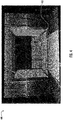
- An exemplary 3-D image of the worksite 100 has been illustrated in FIG. 4 .
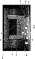
- the exemplary 3-D image 400 of the worksite 100 is illustrated. It can be observed that the exemplary 3-D image 400 corresponds to a 3-D point cloud of the worksite 100, where a plurality of points 402 have been utilized to represent one or more machines and/or the objects in the worksite 100. From FIG. 4 , it can be observed that the plurality of points 402 represents the docked container 102. Further, the plurality of points 402 represent the plurality of articles 120 placed in the docked container 102 and the one or more transitional components 104.
- a first group of regions is identified in the 3-D image (such as the 3-D image 400).
- the image-processing unit 210 is adapted to identify the first group of regions in the 3-D image (such as the 3-D image 400).
- the image-processing unit 210 may be adapted to cluster a set of points of the plurality of points 402 to define a region, based on the orientation of the plurality of points 402 with respect to the material handling apparatus 106. In an exemplary embodiment, the image-processing unit 210 may cluster the set of points having substantially similar orientation with respect to the material handling apparatus 106. In an exemplary embodiment, as discussed above, the orientation of a point of the plurality of points 402 may correspond to a measure of the pitch, the yaw, and the roll of the point with respect to the material handling apparatus 104. For the sake of brevity, hereinafter the term 'orientation' has been used to refer to the phrase "orientation with respect to the material handling apparatus 106".
- the image-processing unit 210 may be adapted to define the region to include a single point (interchangeably referred to as original point) of the plurality of points 402. Thereafter, the image-processing unit 210 may be adapted to determine the orientation of each of one or more points that is adjacent to the original point (included in the region). If the image-processing unit 210 determines that a variance in the orientation of each of the one or more points and the orientation of the original point is within a first predefined range of orientation, the image-processing unit 210 may modify the boundary of the region to include the one or more points. Therefore, the modified region may include the original point and the one or more points adjacent to the original points.
- This process is repeated over the 3-D image (such as 3-D image 400) until the variance between the orientations of the one or more points (adjacent to the points in the region) and the orientations of the original points in the region, is outside the first predefined range of orientation.
- other regions of the first group of regions may be identified in the 3-D image (such as the 3-D image 400).
- the variance of the orientation may be determined between the orientations of the one or more points (adjacent to the region in the 3-D image (such as 3-D image 400) and the orientation of the region.
- the image-processing unit 210 may be adapted to determine the orientation of the region, prior to determining the variance.
- the orientation of the region may correspond to the orientation of a centroid of the region. Therefore, the image-processing unit 210 may be adapted to determine the centroid of the region. Thereafter, the image-processing unit 210 may be adapted to determine the orientation of the centroid of the region.
- the orientation of the centroid of the region may be considered as the orientation of the region itself.
- the image-processing unit 210 may be adapted to determine the variance between the orientation of the region and the orientations of the one or more points adjacent to the region in the 3-D image (such as 3-D image 400).
- the scope of the disclosure is not limited to considering the orientation of the centroid of the region as the orientation of the region.
- the image-processing unit 210 may be adapted to consider the orientation of the center of the region to be the orientation of the region, without departing from the scope of the disclosure.
- the first group of regions identified by the image-processing unit 210 may be representative of the one or more sections of the docked container 102, and the plurality of articles 120 placed in the docked container 102.
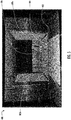
- An exemplary first group of regions is illustrated in FIG. 5 . Referring to FIG. 5 , it can be observed that the image-processing unit 210 has identified the regions 502a, 502b, 504, and 506 as the first group of regions in the exemplary 3-D image 400.
- a second group of regions is identified from the first group of regions.
- the image-processing unit 210 may be adapted to identify the second group of regions from the first group of regions.
- the second group of regions may correspond to the regions that represent the one or more sections of the docked container 102.
- the image-processing unit 210 may be adapted to determine the orientation of each region in the first group of regions. As discussed above, the orientation of a region may correspond to the orientation of the centroid of the region, in an example embodiment.
- the image-processing unit 210 may be adapted to determine the orientation of the respective centroid of the first group of regions.
- the image-processing unit 210 may be adapted to determine the orientation of the first group of regions 502a, 502b, 504, and 506 (identified in the 3-D image 400) by determining the orientation of the respective centroid.
- the image-processing unit 210 may be adapted to check whether the orientation of each region in the first group of regions, such as the regions 502a, 502b, 504, and 506, lies within at least one of one or more second predefined range of orientations.
- the one or more second predefined range of orientations correspond to a range of orientation that a section of the docked container 102 may usually have, when the material handling apparatus 106 is positioned at the second predetermined location in the worksite 100.
- the one or more second predefined range of orientations are pre-stored in the memory 204 prior to starting the operation of the material handling apparatus 106.
- Table 1 The one or more predefined range of orientations Type of section of docked container 102 Range of Pitch (degrees) Range of Yaw (degrees) Range of Roll (degrees) One or more sidewalls 128 0-10 -50 to 50 0 Floor 124 -10 to +10 0 0
- the image-processing unit 210 may be adapted to identify the regions of the first group of regions that represent the one or more sections of the docked container 102.
- the regions identified by the image-processing unit 210 correspond to the second group of regions.
- the image-processing unit 210 determines that the orientation of a region in the first group of regions is 10 degrees pitch, 50 degrees yaw, and 0 degrees roll. Thereafter, the image-processing unit 210 compares the orientation of the region with one or more second predefined ranges of the orientations (illustrated in table 1) to determine that the region may correspond to a sidewall of the one or more sidewalls 128 of the docked container 102. Therefore, the image-processing unit 210 identifies the region as one of the second group of regions. Similarly, the image-processing unit 210 may be adapted to determine whether other regions in the first group of regions correspond to the one or more sections of the docked container 102.
- the image-processing unit 210 may be adapted to store the information pertaining to the second group of regions in the memory 204.
- the information pertaining to the second group of regions may include, but is not limited to, the orientation of each region in the second group of regions, and a type of a section (of the one or more sections of the docked container 102) being represented by each region of the second group of regions.
- the type of the one or more sections may correspond to at least the one or more sidewalls 128 of the docked container 102, the floor 124 of the docked container 102, and the ceiling 126 of the docked container 102.
- An exemplary second group of regions has been illustrated in FIG. 5 .
- the image-processing unit 210 may determine that the regions 502a and 502b represent the one or more sidewalls 128 of the docked container 102. Further, the image-processing unit 210 may determine that the region 504 represents the floor 124 of the docked container 102. As the regions 502a, 502b, and 504 represent the one or more sections of the docked container 102, therefore, the image-processing unit 210 may be adapted to consider the regions 502a, 502b, and 504 as the second group of regions. Further, the image-processing unit 210 may determine that the region 506 is not representing any of the one or more sections of the docked container 102. Therefore, the image-processing unit 210 may not categorize the region 506 as one of the second group of regions.
- a reference point is determined in at least one region of the second group of regions, which represents the one or more sidewalls 128 of the docked container 102.
- the image-processing unit 210 may be adapted to determine the reference point.
- the image-processing unit 210 may be adapted to identify the reference point in each of the regions 502a and 502b (refer to FIG. 5 ), as the regions 502a and 502b represent the two sidewalls 128 of the docked container 102 in the 3-D image 400.
- the image-processing unit 210 may be adapted to retrieve the information pertaining to each region in the second group of regions from the memory 204. Based on the information, the image-processing unit 210 may be adapted to select the at least one region from the second group of regions that represents the one or more sidewalls 128 of the docked container 102. As discussed in the block 306, the information pertaining to the second group of regions includes the type of the one or more sections being represented by each region in the second group of regions. Therefore, based on the information, the image-processing unit 210 may identify the at least one region of the second group of regions that represents a sidewall of the one or more sidewalls 128 of the docked container 102.
- the image-processing unit 210 may be adapted to identify a point of the one or more points (encompassed within the at least one region) that has a minimum elevation, with respect to the ground surface 132, in comparison to the elevation of other points in the at least one region. Further, the identified point has a minimum depth in comparison to other points in the at least one region.
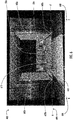
- the image-processing unit 210 defines the identified point as the reference point. For example, referring to FIG. 6 , the reference points 602a and 602b have been identified in the regions 502a and 502b, respectively.
- the first area is defined in the 3-D image based on the reference points (such as the reference points 602a and 602).
- the image-processing unit 210 may be adapted to define the first area. The operation performed in block 310 has been further described in conjunction with FIG. 6 .
- the image-processing unit 210 may be adapted to define an Axis A-A' (depicted by 604) that passes through both the reference points 602a and 602b. Further, the image-processing unit 210 defines an axis B-B' (depicted by 606) such that the axis B-B' (depicted by 606) extends along the length of the sidewall (represented by the region 502a) of the docked container 102 and is substantially parallel to a plane of the region 504 representing the floor 124 of the docked container 102. Further, the Axis B-B' (depicted by 606) passes through the reference point 602a.
- the image-processing unit 210 defines an Axis C-C' (depicted by 608) that passes through the reference point 602b and is substantially parallel to the plane of the region 504 representing the floor of the docked container 102. Further, the Axis C-C' (depicted by 608) extends along the length of the sidewall (represented by the region 502b) of the docked container 102.
- the image-processing unit 210 may be adapted to identify one or more portions of the 3-D image 400 that are encompassed within the Axis A-A' (depicted by 604), the Axis B-B' (depicted by 606), and the Axis C-C' (depicted by 608). From FIG. 6 , it can be observed that there are two such portions (depicted by 610 and 612) of the 3-D image 400 that are encompassed within the Axis A-A' (depicted by 604), the Axis B-B' (depicted by 606), and the Axis C-C' (depicted by 608).
- the image-processing unit 210 may be adapted to select a portion of the one or more portions (such as the portions 610 and 612) in the 3-D image 400 as the first area, based on a measure of depth of the points in each of the one or more portions (such as the portions 610 and 612) in the 3-D image 400.
- the measure of the depth of the points included in the selected portion is less than a measure of the depth of the reference points 602a and 602b. From FIG. 6 , it can be observed that the points included in the portion 610 have a depth less than the depth of the reference points 602a and 602b. Therefore, the portion 610 is selected by the image-processing unit 210 as the first area.
- the first area defines the exterior of the docked container 102.
- the portion 612 (in FIG. 6 ) is considered, by the image-processing unit 210, as the interior of the docked container 102.
- the portion 612 representing the interior of the docked container 102 has been referred to as the second area.
- one or more regions are identified within the first area (such as the first area 610).
- the image-processing unit 210 may be adapted to identify the one or more regions in the first area (such as the first area 610).
- the image-processing unit 210 may employ the methodology described with respect to block 304 to identify the one or more regions in the first area (such as the first area 610).
- the one or more regions in the first area represent the one or more objects that are placed exterior to the docked container 102.
- the one or more objects may include, but are not limited to, an article, and/or the one or more transitional components 104.
- the article may correspond to articles of the plurality of articles 120 (placed in the docked container 102) that might have spilled out of the docked container 102 during opening of the one or more doors of the docked container 102.
- the one or more identified regions in the 3-D image 400 have been illustrated in FIG. 7 .
- the image-processing unit 210 has identified the regions 702, 704, and 706 as the one or more regions in the first area 610 of the 3-D image 400.
- the image-processing unit 210 may be further adapted to identify a type of the one or more objects being represented by the one or more regions (such as the regions 702, 704, and 706).
- the type of the one or more objects may include, but are not limited to, at least one of the one or more transitional components 104, and/or one or more articles.
- the image-processing unit 210 may determine one or more of the orientation and the dimensions of each of the one or more regions (such as the regions 702, 704, and 706).
- the image-processing unit 210 may compare the determined orientation of each of the one or more regions and the dimensions of each of the one or more regions, with a set of third predefined range of orientations and a set of predefined range of dimensions.
- the set of third predefined range of orientations and the set of predefined range of dimensions correspond to known ranges of orientations and dimensions of each type of the one or more objects. Further, the set of third predefined range of orientations and the set of predefined range of dimensions are pre-stored in the memory 204 prior to starting the operation of the material handling apparatus 106.
- Table 2 Third predefined range of orientations and predefined range of dimensions Type of the one or more objects Range of yaw of the object (degrees) Range of pitch of the object (degrees) Range of roll of the object (degrees) Range of dimensions
- One or more transitional components 0-10 30-50 0-20 Length - 10-30 meters Width - 5-10 meters
- NA NA NA Length 10-50 cm length; Height: 70-80 cm height, and width: 20-30 cm
- the image-processing unit 210 determines that a region of the one or more regions has a dimension of 50 cm X 30 cm X 70 cm.
- the image-processing unit 210 may determine the region as the article, as the dimensions of the region are within the range of the dimensions of the articles.
- the image-processing unit 210 may identify the region as the one or more transitional components 104 if the orientation and dimensions of a region lie within the third predefined range of orientations and the predefined range of dimensions of the one or more transitional components 104 (illustrated in table 2).
- the image-processing unit 210 may be adapted to store the information pertaining to the orientation and the dimension of each of the one or more regions as the one or more characteristics associated with each of the one or more objects (represented by the one or more regions).
- the image-processing unit 210 may identify the region 702 as the article based on the orientations and the dimensions of the region 702. Further, the image-processing unit 210 may identify the regions 704 and 706 as the one or more transitional components 104 based on the orientation of the regions 704 and 706, and the dimensions of the regions 704 and 706.
- the material handling apparatus 106 is operated based on the one or more characteristics of the one or more objects (identified in the block 312).
- the processor 202 may be adapted to operate the material handling apparatus 106 based on the one or more characteristics of the one or more objects (for example, the one or more objects identified in the first area 610 of the 3-D image 400).
- the one or more characteristics of the one or more objects may correspond to at least one of the orientation of the one or more objects with respect to the material handling apparatus 106, and the dimensions of the one or more objects.
- the operation of the material handling apparatus 104 has been described in conjunction with FIG. 8 .
- FIG. 8 illustrates a flowchart 800 of a method for operating the material handling apparatus 106, in accordance with one or more embodiments.
- the flowchart 800 is performed post identification of the one or more objects in the block 312.
- the flowchart 800 has been described in conjunction with FIGS. 1 through FIGS. 7 .
- a check is performed to determine whether at least one object of the one or more objects (such as the objects represented by the one or more regions 702, 704, and 706) corresponds to an article.
- the navigation unit 212 is adapted to perform the check.
- the navigation unit 212 may retrieve the information pertaining to the one or more objects (being represented by the one or more regions) from the memory 204.
- the information pertaining to the one or more objects may include the information pertaining to the type of the one or more objects. Therefore, based on the information, pertaining to each of the one or more objects, the navigation unit 212 may be adapted to determine whether at least one object of the one or more objects corresponds to the article. For example, referring to FIG. 7 , the navigation unit 212 may determine that the object represented by the region 702 is an article.
- the navigation unit 212 may be adapted to process the block 804. Else, the navigation unit 212 may be adapted to process the block 810.
- a first notification is generated.
- the notification unit 216 may be adapted to generate the first notification.
- the navigation unit 212 may provide a communication to the notification unit 216 and responsive to receiving and/or processing the communication, the notification unit 216 may generate the first notification.
- the first notification may be indicative of a presence of the article in the exterior of the docked container 102 (for example, the article, represented by the region 702, is present in the first area 610 of the 3-D image 400).
- the processor 202 may be adapted to halt the operation of the material handling apparatus 106 until the article is removed from the exterior (i.e., defined by the first area in the 3-D image) of the docked container 106.
- FIG. 9 An example scenario of determination of the one or more object(s) as the article has been illustrated in FIG. 9 .
- the notification unit 216 may be further adapted to transmit the first notification to the remote control center 110, where the first notification may be displayed on a display device of the application server 130 (placed in the remote control center 110).
- the operator in the remote control center 110 may generate an instruction for a worker in the worksite 100 to remove the article from the first area (such as the first area 610).
- the remote control center 110 in response to receipt and/or processing of the first notification, for example, may be configured to automatically generate an instruction for a worker in the worksite 100 to remove the article from the first area (such as the first area 610) and transmit the instruction to a mobile computing entity associated with the worker.
- the processor 202 may be adapted to repeat the operations explained in the flowchart 300 to determine whether there are any additional articles present in the exterior of the docked container 102.
- the navigation unit 212 in response to the determination that at least one object is an article, may be adapted to determine a second navigation path to a location in proximity to the at least one object. Further, the navigation unit 212 may be adapted to actuate the plurality of traction devices 114 to facilitate a traversal of the material handling apparatus 212 to the location. Thereafter, the processor 202 may instruct the article manipulator unit 214 to actuate the article manipulator 112 to pick the at least one object and place the at least one object at a location outside the first area (for example the first area 610). The operation of the picking and placing of the at least one object may be repeated until all the objects (identified as articles) are removed from the first area.
- An exemplary second navigation path has been illustrated in FIG. 9 .
- the navigation unit 212 may be adapted to traverse the material handling apparatus 106 along a path back to the predetermined second location, where the operation described in the flowchart 300 is repeated.
- the operation of picking and placing the at least one object may be performed in addition to generation of the first notification.
- the first navigation path ingress to the docked container 102 is determined.
- the navigation unit 212 may be adapted to determine the first navigation path ingress to the docked container 102.
- the first navigation path ingress to the docked container 102 is determined based on the identification of the plurality of articles 120 placed in the docked container 102. The identification of the plurality of articles 120 and the determination of the first navigation path ingress to docked container 102 has been described later in conjunction with FIG. 10 .
- the operation of the material handling apparatus 106 is activated.
- the processor 202 may be adapted to activate the operation of the material handling apparatus 106.
- the activation of the material handling apparatus 106 includes activation of a vision system (not shown) installed in the material handling apparatus 106. Thereafter, the material handling apparatus 106 operates in accordance to the image captured by the vision system. In an exemplary embodiment, the vision system is different from the one or more image-capturing devices 108a and 108b.
- the operation at block 810 is performed.
- the one or more characteristics of the one or more transitional components 104 are retrieved from the memory 204.
- the processor 202 may be adapted to retrieve the one or more characteristics.
- the one or more characteristics of the one or more transitional components 104 may include, but are not limited to, the orientation of the one or more transitional components, and the dimension of the of the one or more transitional components 104.
- the orientation of each of the one or more transitional components 104 is compared within a fourth predefined range of the orientation.
- the processor 202 may be adapted to perform the comparison.
- the processor 202 may be adapted to perform the operation in the block 806. Else the processor 202 may be adapted to perform the operation in the block 814.
- the one or more transitional components 104 include the ramp 134 and the dock leveler 136. Therefore, while performing the comparison, the processor 202 may be adapted to compare the orientation of the ramp 134 with the fourth predefined range of orientation associated with the ramp 134. Similarly, the processor 202 may be adapted to perform the comparison of the orientation of the dock leveler 136 with the fourth predefined range of orientation associated with the dock leveler 136. If the processor 202 determines that the orientation of at least one of the ramp 134 or the dock leveler 136 is within the respective range of the orientation, the processor 202 may be configured to perform the operation in the block 806. Else the processor 202 may be adapted to perform the operation in the block 814.
- a second notification is generated.
- the notification unit 216 may be adapted to generate the second notification.
- the second notification is indicative of a misalignment between the one or more transitional components 104 and the floor 124 of the docked container 102.
- the processor 202 may be adapted to transmit the second notification to the remote control center 110, where the second notification may be displayed on the display device of the application server 130. Based on the generated second notification, the operator in the remote control center 110 may instruct a worker in the worksite 100 to correct the alignment between the one or more transitional components 104 and the floor 124 of the docked container 102.
- the remote control center 110 may be configured to automatically generate an instruction for a worker in the worksite 100 to correct the alignment between the one or more transitional components 104 and the floor 124 of the docked container 102 and transmit the instruction to a mobile computing entity associated with the worker.
- the operator may directly provide an input (e.g., via a user input device of the remote control center 110) to correct the misalignment between the one or more transitional components 104 and the floor 124 of the docked container 102.
- FIG. 9 illustrates the exemplary scenario 900 of operating the material handling apparatus 106, in accordance with one or more exemplary embodiments.
- the exemplary scenario 900 has been described in conjunction with FIGS. 3 through FIGS. 8 .
- the exemplary scenario 900 illustrates the 3-D image 400. Further, it can be observed from FIG. 9 that the 3-D image 400 includes the first area 610. Further, in the first area 610, the one or more regions 902, 904, 906, 908, and 910 are identified by the image-processing unit 210. The process of identification of the type of the one or more objects represented by the one or more regions (902, 904, 906, 908, and 910) has been described with respect to block 312. For example, the image-processing unit 210 identifies the regions 902 and 904 as the ramp 134 and the dock leveler 136 (i.e., the one or more transitional components 104), respectively.
- the image-processing unit 210 identifies the regions 902 and 904 as the ramp 134 and the dock leveler 136 (i.e., the one or more transitional components 104), respectively.
- the image-processing unit 210 identifies the regions 906, 908, and 910 as the articles based on the dimensions of the regions 906, 908, and 910. Further, it can be observed that the article (represented by the region 908) partially lies in the first area 610. In an exemplary embodiment, the image-processing unit 210 may consider the article (represented by the region 908) as an obstruction even if a part of the region 908 lies outside the first area 610. In an exemplary embodiment, the processor 202 does not activate the operation of the material handling apparatus 106 until all the articles (represented by the regions 906, 908, and 910) are removed from the first area 610.
- the second navigation path 912 has been illustrated. It can be observed that the second navigation path 912 includes one or more locations 914, 916, and 918. The location 912 is in proximity to the location of the article represented by the region 910. Similarly, the locations 914 and 916 are in proximity to the locations of the articles represented by the regions 908 and 906, respectively. In an embodiment, the material handling apparatus 106 may traverse along the second navigation path 912 to the locations 914, 916, and 918 to pick the articles in proximity of the respective locations 914, 916, and 918.
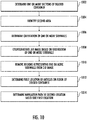
- FIG. 10 illustrates a flowchart 1000 of a method for picking the plurality of articles 120 loaded in a docked container 102.
- the flowchart 1000 has been described in conjunction with FIGS. 1 through FIGS. 9 .
- the one or more sections of the docked container 102 are determined.
- the image-processing unit 210 may be adapted to determine the one or more sections of the docked container 102 using the methodologies described with respect to block 306 in the flowchart 300.
- the second area is identified in the 3-D image (such as the 3-D image 400).
- the image-processing unit 210 may be adapted to determine the second area in the 3-D image.
- the second area 612 is identified in the 3-D image 400.
- the second area in the 3-D image may be representative of the interior of the docked container 102.
- the image-processing unit 210 may utilize the methodologies described with respect to blocks 308 and the block 310 to identify the second area.
- the orientation of the one or more sidewalls 128 of the docked container 102 is determined.
- the image-processing unit 210 may be adapted to determine the orientation of the one or more sidewalls 128 of the docked container 102.
- the image-processing unit 210 may be adapted to determine the centroid of the regions (such as the regions 502a and 502b) representing the one or more sidewalls 128 of the docked container 102.
- the 3-D image of the worksite 100 is counter rotated in accordance with the orientation of each of the one or more sidewalls 128 of the docked container 102.
- the image-processing unit 210 may be adapted to counter rotate the 3-D image.
- the image-processing unit 210 may counter rotate the 3-D image until an absolute value at least one parameter of the orientation of each of the one or more sidewalls 128 is equal.
- the at least one parameter of the orientation may correspond to at least one of a yaw, pitch, and roll.
- the 3-D image is counter rotated until absolute value of yaw of a sidewall of the one or more sidewalls 128 of the docked container 102 becomes equal to the absolute value of yaw of the other sidewall of the one or more sidewalls 128 of the docked container 102.
- the image-processing unit 210 may be adapted to counter rotate the 3-D image by 10 degrees such that the value of yaw of the sidewall is 50 degrees and the value of yaw of the other sidewall is - 50 degrees.
- the regions representing the one or more sidewalls 128 (for example the regions 502a and 502b) of the docked container 102 are removed from the 3-D image.
- the image-processing unit 210 may be adapted to remove the regions representing the one or more sidewalls 128 of the docked container 102.
- the second area (representing the interior of the docked container 210) only includes the region representing the floor 124 of the docked container 102 and the regions representing the plurality of articles 120.
- the 3-D image includes the regions 504 (representing the floor 124) and the region 506 (representing the plurality of articles 120).
- a first location of the plurality of articles 120 on the floor 124 of the docked container 102 is determined.
- the image-processing unit 210 may be adapted to determine the first location of the plurality of articles 120 on the floor 124 of the docked container 102.
- the first location of the plurality of articles 120 on the floor 124 of the docked container 102 may be determined based on the depth of the points representing the plurality of articles 120 in the 3-D image (for example the 3-D image 400).
- the first navigation path to a second location is determined based on the first location of the plurality of articles 120.
- the navigation unit 212 may be configured to determine the first navigation path. Prior to determining the first navigation path, the navigation unit 212 may be configured to determine the second location.
- the second location may correspond to a location where the material handling apparatus 106 will be positioned to pick at least one of the plurality of articles 120.
- a check is performed to determine whether the first location of the plurality of articles 120 is within a predetermined distance from a junction of the floor 124 of the docked container 102 and the one or more transitional components 104.
- the predetermined distance may correspond to a maximum distance from which the article manipulator 112 can fetch the articles from the plurality of articles 120. If the navigation unit 212 determines that the first location of the plurality of articles 120 is within the predetermined distance from the junction, the navigation unit 212 may be adapted to determine the second location in the first area of the 3-D image. Since the first area represents the exterior of the docked container 106 in the 3-D image, therefore, the second location may lie exterior to the docked container 102.
- the determination of the second location to the exterior (i.e., the first area in the 3-D image) of the docked container 102 is indicative of the plurality of articles 102 being placed near to the one or more doors 122 of the docked container 102.
- the material handling apparatus 106 will position itself exterior to the docked container 106.
- the navigation unit 212 may determine the second location within the interior of the docked container 102 (e.g., within second area 612).
- the navigation unit 212 may be configured to determine the first navigation path to the second location (e.g., from the current location of the material handling apparatus 106).
- the material handling apparatus 106 may traverse the first navigation path to the second location in order to pick one or more articles of the plurality of articles 120.
- the one or more articles are placed within the predetermined distance from the junction of the floor 124 of the docked container 102 and the one or more transitional components 104.
- the disclosed embodiments encompass numerous advantages.
- the disclosed embodiments illustrate methods and systems that allow detection of the articles in the exterior of the docked container 102 prior to initiating the operation of the material handling apparatus 106. This allows the system to generate timely notifications that may alert the operator of the material handling apparatus 106 beforehand. Accordingly, the operator may remove the articles before the operation of the material handling apparatus 106 can be started.
- a person having ordinary skills in the art would appreciate that the scope of the disclosure is not limited to detecting articles in the exterior of the docked container 102.
- other entities such as humans can also be detected exterior to the docked container 102.
- the disclosed systems and methods describe embodiments where the material handling apparatus 106 itself picks and places the articles in the exterior to the docked container 102. Such an exemplary embodiment ensures that no article (e.g., an article that might have spilled out of the docked container 102 during docking of the container 102 in the worksite 100) is missed by the material handling apparatus 106.
Landscapes
- Engineering & Computer Science (AREA)
- Mechanical Engineering (AREA)
- Robotics (AREA)
- Physics & Mathematics (AREA)
- Aviation & Aerospace Engineering (AREA)
- Automation & Control Theory (AREA)
- Computer Vision & Pattern Recognition (AREA)
- Electromagnetism (AREA)
- Radar, Positioning & Navigation (AREA)
- Remote Sensing (AREA)
- General Physics & Mathematics (AREA)
- Optics & Photonics (AREA)
- Multimedia (AREA)
- Human Computer Interaction (AREA)
- Manipulator (AREA)
Applications Claiming Priority (2)
| Application Number | Priority Date | Filing Date | Title |
|---|---|---|---|
| US201862634367P | 2018-02-23 | 2018-02-23 | |
| US16/258,975 US20190262994A1 (en) | 2018-02-23 | 2019-01-28 | Methods and systems for operating a material handling apparatus |
Publications (1)
| Publication Number | Publication Date |
|---|---|
| EP3530601A1 true EP3530601A1 (fr) | 2019-08-28 |
Family
ID=65493831
Family Applications (1)
| Application Number | Title | Priority Date | Filing Date |
|---|---|---|---|
| EP19157600.8A Withdrawn EP3530601A1 (fr) | 2018-02-23 | 2019-02-15 | Procédés et systèmes de fonctionnement d'un appareil de manipulation de matériau |
Country Status (3)
| Country | Link |
|---|---|
| US (1) | US20190262994A1 (fr) |
| EP (1) | EP3530601A1 (fr) |
| CN (1) | CN110182500A (fr) |
Cited By (3)
| Publication number | Priority date | Publication date | Assignee | Title |
|---|---|---|---|---|
| EP3848305A1 (fr) * | 2020-01-10 | 2021-07-14 | Becton Dickinson Rowa Germany GmbH | Procédé de fonctionnement d'un dispositif de préparation de commandes pour médicaments ainsi que dispositif de préparation de commandes permettant de mettre en oeuvre le procédé |
| US11286111B2 (en) | 2020-01-10 | 2022-03-29 | Becton Dickinson Rowa Germany Gmbh | Method for operating a picking device for medicaments and a picking device for carrying out said method |
| EP4140935A1 (fr) * | 2021-04-22 | 2023-03-01 | STILL GmbH | Procédé de commande d'un chariot de manutention autonome |
Families Citing this family (9)
| Publication number | Priority date | Publication date | Assignee | Title |
|---|---|---|---|---|
| CA3139267C (fr) | 2016-12-09 | 2023-07-25 | Berkshire Grey, Inc. | Systemes et procedes de traitement d'objets disposes dans des vehicules |
| US11436753B2 (en) | 2018-10-30 | 2022-09-06 | Liberty Reach, Inc. | Machine vision-based method and system to facilitate the unloading of a pile of cartons in a carton handling system |
| CN111908155A (zh) * | 2020-09-10 | 2020-11-10 | 佛山科学技术学院 | 一种集装箱机器人自动装卸系统 |
| US12437441B2 (en) | 2021-01-05 | 2025-10-07 | Liberty Robotics Inc. | Method and system for decanting a plurality of items supported on a transport structure at one time with a picking tool for placement into a transport container |
| US12444080B2 (en) | 2021-01-05 | 2025-10-14 | Liberty Robotics Inc. | Method and system for manipulating a multitude of target items supported on a substantially horizontal support surface one at a time |
| US12450773B2 (en) | 2021-01-05 | 2025-10-21 | Liberty Robotics Inc. | Method and system for manipulating a target item supported on a substantially horizontal support surface |
| US12142048B2 (en) * | 2021-09-28 | 2024-11-12 | Kargo Technologies Corporation | Freight management systems and methods |
| US12142049B2 (en) * | 2021-09-28 | 2024-11-12 | Kargo Technologies Corporation | Freight management systems and methods |
| CA3234674A1 (fr) | 2021-10-06 | 2023-04-13 | Berkshire Grey Operating Company, Inc. | Traitement dynamique d'objets fournis dans des vehicules sureleves a systemes d'evacuation et procedes de reception d'objets |
Citations (2)
| Publication number | Priority date | Publication date | Assignee | Title |
|---|---|---|---|---|
| US20160104364A1 (en) * | 2014-10-08 | 2016-04-14 | Andrew Brooks | Methods and apparatus for monitoring a dock leveler |
| US9688489B1 (en) * | 2015-03-30 | 2017-06-27 | X Development Llc | Modular dock for facilities integration |
Family Cites Families (2)
| Publication number | Priority date | Publication date | Assignee | Title |
|---|---|---|---|---|
| CN106395430A (zh) * | 2016-11-24 | 2017-02-15 | 南京景曜智能科技有限公司 | 一种3d立体视觉辅助装卸车系统 |
| CN107117470A (zh) * | 2017-06-19 | 2017-09-01 | 广州达意隆包装机械股份有限公司 | 一种装车机器人及其装车方法 |
-
2019
- 2019-01-28 US US16/258,975 patent/US20190262994A1/en not_active Abandoned
- 2019-02-15 EP EP19157600.8A patent/EP3530601A1/fr not_active Withdrawn
- 2019-02-21 CN CN201910136023.8A patent/CN110182500A/zh active Pending
Patent Citations (2)
| Publication number | Priority date | Publication date | Assignee | Title |
|---|---|---|---|---|
| US20160104364A1 (en) * | 2014-10-08 | 2016-04-14 | Andrew Brooks | Methods and apparatus for monitoring a dock leveler |
| US9688489B1 (en) * | 2015-03-30 | 2017-06-27 | X Development Llc | Modular dock for facilities integration |
Cited By (5)
| Publication number | Priority date | Publication date | Assignee | Title |
|---|---|---|---|---|
| EP3848305A1 (fr) * | 2020-01-10 | 2021-07-14 | Becton Dickinson Rowa Germany GmbH | Procédé de fonctionnement d'un dispositif de préparation de commandes pour médicaments ainsi que dispositif de préparation de commandes permettant de mettre en oeuvre le procédé |
| WO2021139966A1 (fr) * | 2020-01-10 | 2021-07-15 | Becton Dickinson Rowa Germany Gmbh | Procédé permettant de faire fonctionner un dispositif de préparation de commandes pour des médicaments et dispositif de préparation de commandes pour mettre en œuvre ledit procédé |
| US11286111B2 (en) | 2020-01-10 | 2022-03-29 | Becton Dickinson Rowa Germany Gmbh | Method for operating a picking device for medicaments and a picking device for carrying out said method |
| US11919712B2 (en) | 2020-01-10 | 2024-03-05 | Becton Dickinson Rowa Germany Gmbh | Method for operating a picking device for medicaments and a picking device for carrying out said method |
| EP4140935A1 (fr) * | 2021-04-22 | 2023-03-01 | STILL GmbH | Procédé de commande d'un chariot de manutention autonome |
Also Published As
| Publication number | Publication date |
|---|---|
| US20190262994A1 (en) | 2019-08-29 |
| CN110182500A (zh) | 2019-08-30 |
Similar Documents
| Publication | Publication Date | Title |
|---|---|---|
| EP3530601A1 (fr) | Procédés et systèmes de fonctionnement d'un appareil de manipulation de matériau | |
| US11465864B2 (en) | Perception-based robotic manipulation system and method for automated truck unloader that unloads/unpacks product from trailers and containers | |
| CN106573381B (zh) | 卡车卸载机可视化 | |
| US20240408750A1 (en) | Machine learning based decision making for robotic item handling | |
| US9776511B2 (en) | Vehicle alignment systems for loading docks | |
| TW202221632A (zh) | 貨物存放方法、裝置、機器人、倉儲系統及儲存媒體 | |
| JP7199003B2 (ja) | 搬送装置、受信機能付き搬送装置、搬送システム、上位システム、搬送装置の制御方法、及びプログラム | |
| US10657666B2 (en) | Systems and methods for determining commercial trailer fullness | |
| JP2017097847A (ja) | 搬送装置、搬送システム、および搬送方法 | |
| US12508727B2 (en) | Closed loop solution for loading/unloading cartons by truck unloader | |
| US11847832B2 (en) | Object classification for autonomous navigation systems | |
| EP3656702A1 (fr) | Robot industriel mobile comportant un système de sécurité pour l'arrimage des palettes | |
| US11905125B1 (en) | Parcel cart loading system | |
| WO2019012802A1 (fr) | Dispositif de grue | |
| US20190127148A1 (en) | System and Methods for Automated Storage Receptacle Processing | |
| KR102863328B1 (ko) | 화물 트럭에 자동 이적재를 위한 팔레트와 화물의 인식 방법 및 시스템 | |
| WO2017082385A1 (fr) | Dispositif de transport, système de transport, et procédé de transport | |
| EP4711095A1 (fr) | Système et procédé de dépalettisation robotique | |
| EP4576007A1 (fr) | Systèmes et procédés de surveillance de cargaison | |
| CN120112391A (zh) | 具有用于转移未注册物体的动态运动计划的机器人系统 | |
| WO2022264381A1 (fr) | Dispositif de calcul de comptage de récupération de pièce à travailler, système de main et dispositif d'affichage |
Legal Events
| Date | Code | Title | Description |
|---|---|---|---|
| PUAI | Public reference made under article 153(3) epc to a published international application that has entered the european phase |
Free format text: ORIGINAL CODE: 0009012 |
|
| STAA | Information on the status of an ep patent application or granted ep patent |
Free format text: STATUS: REQUEST FOR EXAMINATION WAS MADE |
|
| 17P | Request for examination filed |
Effective date: 20190215 |
|
| AK | Designated contracting states |
Kind code of ref document: A1 Designated state(s): AL AT BE BG CH CY CZ DE DK EE ES FI FR GB GR HR HU IE IS IT LI LT LU LV MC MK MT NL NO PL PT RO RS SE SI SK SM TR |
|
| AX | Request for extension of the european patent |
Extension state: BA ME |
|
| STAA | Information on the status of an ep patent application or granted ep patent |
Free format text: STATUS: THE APPLICATION HAS BEEN WITHDRAWN |
|
| 18W | Application withdrawn |
Effective date: 20210305 |