EP3530793B1 - Waschmaschine mit einer dichtanordnung für eine lageranordnung eines laugenbehälters der waschmaschine - Google Patents
Waschmaschine mit einer dichtanordnung für eine lageranordnung eines laugenbehälters der waschmaschine Download PDFInfo
- Publication number
- EP3530793B1 EP3530793B1 EP19156135.6A EP19156135A EP3530793B1 EP 3530793 B1 EP3530793 B1 EP 3530793B1 EP 19156135 A EP19156135 A EP 19156135A EP 3530793 B1 EP3530793 B1 EP 3530793B1
- Authority
- EP
- European Patent Office
- Prior art keywords
- outer tub
- washing machine
- plastic part
- bearing
- base
- Prior art date
- Legal status (The legal status is an assumption and is not a legal conclusion. Google has not performed a legal analysis and makes no representation as to the accuracy of the status listed.)
- Active
Links
Images
Classifications
-
- D—TEXTILES; PAPER
- D06—TREATMENT OF TEXTILES OR THE LIKE; LAUNDERING; FLEXIBLE MATERIALS NOT OTHERWISE PROVIDED FOR
- D06F—LAUNDERING, DRYING, IRONING, PRESSING OR FOLDING TEXTILE ARTICLES
- D06F37/00—Details specific to washing machines covered by groups D06F21/00 - D06F25/00
-
- D—TEXTILES; PAPER
- D06—TREATMENT OF TEXTILES OR THE LIKE; LAUNDERING; FLEXIBLE MATERIALS NOT OTHERWISE PROVIDED FOR
- D06F—LAUNDERING, DRYING, IRONING, PRESSING OR FOLDING TEXTILE ARTICLES
- D06F37/00—Details specific to washing machines covered by groups D06F21/00 - D06F25/00
- D06F37/02—Rotary receptacles, e.g. drums
Definitions
- the invention is in the field of washing machines, in particular so-called front-loading washing machines with a sealing arrangement for the laundry drum bearing, and relates to a washing machine with a suds container with a suds container base, with a laundry drum which is arranged in the suds container, with a shaft journal which is connected to the laundry drum and which extends through an opening in the suds container base, with a bearing housing for receiving a bearing arrangement in which the shaft journal is rotatably mounted, with a sealing arrangement which seals the opening with respect to the bearing arrangement, and with a shield which shields the sealing arrangement.
- washing machine is generally understood to mean a laundry treatment machine that treats laundry in a washing drum.
- the term washing machine therefore includes, for example, both classic washing machines and so-called washer-dryers, which combine the functions of a washing machine and a tumble dryer.
- a washing machine of the type mentioned at the beginning which has a substantially cylindrical laundry drum that is rotatably mounted in a lye container made of lye-resistant plastic.
- the lye container has an opening in the center of its lye container base, in or behind which a bearing housing is arranged in the axial direction away from the lye container.
- the bearing housing is supported by a bearing cross that is attached to the edge of the outer surface or directly to the base of the lye container.
- a shaft journal is connected to the drum in a rotationally fixed manner via a flange attached to the base of the laundry drum and extends through the opening in the lye container base.
- a sealing arrangement protects the radial ball bearing near the lye container from washing lye and for this purpose comprises an elastic radial shaft sealing ring that is connected to several dynamically loaded Sealing lips rest on a race on the shaft journal side.
- the sealing arrangement can be inserted into the inner bore of the bearing housing or into an opening in front of it in the bearing container base.
- the radial shaft seal is exposed to washing solution or foreign substances, dirt particles or fluff contained therein. This can damage the sealing lips or the raceway, so that washing solution can penetrate into the bearing arrangement. This can lead to premature wear and, in the worst case, to bearing damage.
- the pre-shielding consists of a circumferential ring with a U-shaped or V-shaped cross-section that is open to the outside and which concentrically surrounds the radial shaft sealing ring. This protects the radial shaft sealing ring from being sprayed with washing liquor when the washing drum is rotating, thus preventing or at least reducing the penetration of foreign particles and/or washing liquor into the sealing zone.
- the pre-shielding of the sealing arrangement can be arranged in front of the suds container in the axial direction.
- the pre-shielding is molded in one piece onto the rest of the lye container base and is manufactured at the same time using the injection molding process. This is technically demanding in terms of production and requires complex injection molding tools due to the demoldable undercuts in the lye container required to create the shielding and makes it difficult to remove the lye container from the injection mold.
- the DE 101 33 892 A1 discloses a sealing system, in particular for a washing machine, in which at least one sealing lip made of an elastomeric material is directed towards a drum pin and a seal arranged between the sealing lip and a lye side of the washing machine has a sealing disk made of polytetrafluoroethylene.
- one object of the invention is to provide a washing machine with a reliable shielding of the sealing arrangement for sealing the opening in the tub base, which is characterized by a simplified and cost-effective manufacturability.
- the shield is formed from at least one separately manufactured plastic part which is connected to the tub and/or to the bearing housing.
- An embodiment of the invention selected for assembly purposes provides that the lye container and/or the bearing housing has a support web with at least one recess in which at least one fitting part of the plastic part is accommodated. This embodiment ensures reliable centering and a correct fit of the plastic part in a particularly secure manner.
- the fitting part can preferably be an annular, axially extending web.
- the washing machine according to the invention is characterized by particular advantages in the manufacture of the (plastic) suds container. This is because the undercuts required according to the state of the art mentioned at the beginning, which are difficult to remove from the injection mold (demold), can be dispensed with. The construction and design of the injection molding tools are thus considerably simplified.
- the geometry of the shield can be selected and optimized independently of limitations of the injection molding tool or the injection molding process, so that a particularly effective function of the shield is achieved and the shielding effect is optimized.
- the separately manufactured plastic part can be subsequently connected to the lye container (direct connection to the lye container) or to the bearing housing (indirect connection to the lye container) in a material-locking, force-locking and/or form-locking manner after its manufacture.
- This results in particular advantages in the production of the lye container if the plastic part is initially inserted into the injection mold as a separately prefabricated part in a two-component manufacturing process and the connection between the plastic part and the lye container or the bearing housing is produced by the second injection molding process step, which is, for example, overmolding or backmolding of the plastic part.
- This makes it possible to create a permanent and firm connection between the plastic part and the lye container or the bearing housing in a particularly cost-effective manner.
- the plastic part consists of elastomer.
- a first significant advantage of this embodiment is the improved sealing function of the shield due to the elastomer properties.
- the arrangement is therefore particularly resistant to foreign particles and resistant to foreign particles, which leads to an increase in the bearing life and thus the operating time of the washing machine according to the invention. This results in particular advantages in the production of the suds container if the elastomer part is inserted into the injection mold in a two-component manufacturing process as an initially separately prefabricated part.
- the injection molding tool design may be somewhat more complex; however, this increased effort is minimized compared to the state of the art mentioned at the beginning on the one hand by the fact that the elastomer part is elastically deformable and thus easier to remove from the injection mold (demold), and on the other hand by the fact that additional assembly steps or fixing work on the plastic part are eliminated.
- the washing machine 1 shown in the figures has a substantially cylindrical tub 2 in which a substantially cylindrical
- the washing drum 3 is arranged so as to be rotatable about a horizontal axis of rotation.
- the tub 2 is made of lye-resistant plastic and comprises a base 4, which forms the rear end face (in a washing machine that is usually front-loaded) of the tub.
- the base 4 has an opening 5, behind which in the axial direction, away from the tub, in itself - for example from the initially mentioned EP 1 514 966 B1 , to which reference is made in this regard - a bearing housing 8 is arranged in a known manner.
- the bearing housing 8 is supported by a bearing cross (not shown) which is connected to the tub 2 or to the base 4.
- the washing drum 3 has a flange 10 which is connected in a rotationally fixed manner to a shaft journal 12.
- the shaft journal 12 projects through the opening 5 and is accommodated in the bearing housing 8 by a bearing arrangement 13 made of radial bearings, as is basically shown in the EP 1 514 966 B1 described in detail.
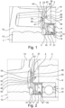
- An elastic radial shaft seal 15 with several dynamically stressed sealing lips 16, 17 and 18 is located in the front radial bearing 14 near the tub (only partially visible). The sealing lip 18 is pressed onto a running surface 21 of the shaft journal 12 via an annular spring 20. Concentric to the radial shaft seal 15 is a shield 30 ( Figure 1 ) or 31 ( Figure 2 ) is provided.
- the shield 30 consists of a separately manufactured plastic part 33, which has an approximately T-shaped circumferential cross-section 34.
- the base leg of the T-shape designed as a web 36, extends into a support web 37 of the suds container 2 in the area of the container bottom 4, which for this purpose has a circumferential recess 38 in the form of an annular groove.
- the free end of the web 36 designed as a fitting part 39, is fitted into this recess.
- the lateral legs 40, 41 of the T-shape of the plastic part 33 are essentially oriented radially, with the radially outwardly oriented leg 40 together with the web 36 and the facing surface 42 of the suds container forming a circumferential U-shaped groove or channel 43 with the opening pointing radially outwards, in which washing suds or suds splashing into the area of the storage collect and are drained away around the storage.
- the plastic part 33 is preferably fixed in the recess 38 by means of a form fit 44 or a material fit (for example by gluing). Suitable dimensioning can also achieve a force fit by means of a press fit.
- the shield 31 shown is made of an elastomer 48. It has a circumferential cross-sectional shape 50 in the form of a slightly opened "L".
- the shorter leg 51 of the L-shape is inserted into a circumferential groove or recess 52 in the base 4 of the suds container 2 and is held there in a material-locking manner by adhesive 53.
- the longer leg 54 of the L-shape which is free in the cross-sectional profile, forms a suds-side flank 55 of the shield 31. This flank, together with the leg 51 and the facing upper side 56 of the base 4, forms a circumferential discharge channel 57 in which washing suds and particles contained therein collect and are drained away around the bearing arrangement 13.
- the shield 31 is flexible and yielding due to the elastomer properties of the plastic, which has a positive effect on the durability and longevity of the shield.
- relatively small distances to neighboring (moving) parts such as the flange 10 can be achieved because even if foreign particles accumulate there, the flexibility of the lip formed by the leg 54 allows the shield 31 to move away without causing any damage and thus extending its service life.
- the shield is particularly preferably produced in a 2-component manufacturing process in a common injection mold for the lye container 2, which can then be overmolded with the lye-resistant plastic (2nd component), and the injection mold is therefore somewhat more complex to design due to the undercuts, demolding is nevertheless made easier by the elastic properties of the elastomer 48 and additional assembly steps are also saved because no additional fastening or connection of the elastomer part 48 to the lye container 2 is required.
Landscapes
- Engineering & Computer Science (AREA)
- Textile Engineering (AREA)
- Main Body Construction Of Washing Machines And Laundry Dryers (AREA)
Description
- Die Erfindung liegt auf dem Gebiet der Waschmaschinen, insbesondere sogenannter frontseitig zu beschickender Frontladerwaschmaschinen, mit einer Dichtungsanordnung für die Wäschetrommellagerung und betrifft eine Waschmaschine mit einem Laugenbehälter mit einem Laugenbehälterboden, mit einer Wäschetrommel, die in dem Laugenbehälter angeordnet ist, mit einem Wellenzapfen, der mit der Wäschetrommel verbunden ist und der sich durch eine Öffnung in dem Laugenbehälterboden erstreckt, mit einem Lagergehäuse zur Aufnahme einer Lageranordnung, in der der Wellenzapfen drehbar gelagert ist, mit einer Dichtungsanordnung, die die Öffnung gegenüber der Lageranordnung abdichtet, und mit einer Abschirmung, die die Dichtungsanordnung abschirmt.
- Im Rahmen der vorliegenden Erfindung ist unter einer Waschmaschine allgemein eine Wäschebehandlungsmaschine zu verstehen, die in einer Wäschetrommel befindliche Wäsche einer Behandlung unterzieht. Der Begriff Waschmaschine im umfasst damit beispielsweise sowohl klassische Waschmaschinen als auch sog. Waschtrockner, die die Funktionen einer Waschmaschine und eines Wäschetrockners vereinen.
- Aus der Europäischen Patentschrift
EP 1 514 966 B1 undEP 1 514 965 A2 ist jeweils eine Waschmaschine der eingangs genannten Art bekannt, die eine im Wesentlichen zylindrische Wäschetrommel aufweist, die in einem aus laugenbeständigem Kunststoff hergestellten Laugenbehälter drehbar gelagert ist. Der Laugenbehälter weist im Zentrum seines Laugenbehälterbodens eine Öffnung auf, in oder hinter der in axialer Richtung laugenbehälterfern ein Lagergehäuse angeordnet ist. Das Lagergehäuse ist von einem Lagerkreuz getragen, das am Rand der Mantelfläche oder direkt am Boden des Laugenbehälters befestigt ist. Ein Wellenzapfen ist über einen am Boden der Wäschetrommel befestigten Flansch drehfest mit dieser verbunden und erstreckt sich durch die Öffnung des Laugenbehälterbodens. Zwei in eine Innenbohrung des Lagergehäuses eingesetzte Radialkugellager bilden eine Lageranordnung, die den Wellenzapfen der Wäschetrommel aufnimmt. Eine Dichtungsanordnung schützt das laugenbehälternahe Radialkugellager vor Waschlauge und umfasst dazu einen elastischen Radialwellendichtring, der mit mehreren dynamisch beanspruchten Dichtlippen an einem wellenzapfenseitigen Laufring anliegt. Die Dichtungsanordnung kann in die Innenbohrung des Lagergehäuses oder in eine davor befindliche Öffnung des Lagerbehälterbodens eingesetzt sein. - Während des Waschvorgangs wird der Radialwellendichtring mit Waschlauge bzw. darin befindlichen Fremdstoffen, Schmutzpartikeln oder Flusen beaufschlagt. Dadurch können die Dichtlippen bzw. die Laufbahn geschädigt werden, so dass Waschlauge in die Lageranordnung eindringen kann. Dies kann zu einem vorzeitigen Verschleiß und ungünstigstenfalls zu Lagerschäden führen.
- Deshalb ist bei der bekannten Waschmaschine eine sogenannte Vorabschirmung vorgesehen. Die Vorabschirmung besteht aus einem Umlaufring mit U-förmigem oder V-förmigem nach außen geöffnetem Querschnitt, der den Radialwellendichtring konzentrisch umgibt. Dadurch ist der Radialwellendichtring vor einer Berieselung mit Waschlauge bei sich drehender Wäschetrommel geschützt und so ein Eindringen von Fremdpartikeln und/oder Waschlauge in die Dichtzone verhindert, zumindest aber vermindert. Alternativ kann die Vorabschirmung der Dichtungsanordnung in axialer Richtung laugenbehälterseitig vorangestellt angeordnet sein.
- Die Vorabschirmung ist einstückig an den übrigen Laugenbehälterboden angeformt und wird gleichzeitig mit diesem im Spritzgussverfahren hergestellt. Dies ist fertigungstechnisch anspruchsvoll und erfordert wegen der für die Realisierung der Abschirmung erforderlichen entformbaren Hinterschnitte des Laugenbehälters aufwändige Spritzgusswerkzeuge und verursacht eine diffizile Entnahme des Laugenbehälters aus der Spritzgussform.
- Die
DE 101 33 892 A1 offenbart ein Dichtungssystem, insbesondere für eine Waschmaschine, bei welcher wenigstens eine Dichtlippe aus einem elastomeren Werkstoff auf einen Trommelzapfen gerichtet ist und eine zwischen der Dichtlippe und einer Laugenseite der Waschmaschine angeordnete Dichtung eine Dichtscheibe aus Polytetrafluorethylen aufweist. - Vor diesem Hintergrund besteht eine Aufgabe der Erfindung in der Bereitstellung einer Waschmaschine mit einer zuverlässigen Abschirmung der Dichtungsanordnung zur Abdichtung der Öffnung in dem Laugenbehälterboden, die sich durch eine vereinfachte und kostengünstige Herstellbarkeit auszeichnet.
- Diese Aufgabe wird erfindungsgemäß bei einer Waschmaschine der eingangs genannten Art mit den Merkmalen der unabhängigen Ansprüche 1 oder 6 gelöst. Dabei ist die Abschirmung aus wenigstens einem separat gefertigten Kunststoffteil gebildet, das mit dem Laugenbehälter und/oder mit dem Lagergehäuse verbunden ist.
- Eine montagetechnisch gewählte Ausgestaltung der Erfindung sieht vor, dass der Laugenbehälter und/oder das Lagergehäuse einen Tragsteg mit wenigstens einer Ausnehmung aufweist, in der wenigstens ein Passteil des Kunststoffteils aufgenommen ist. Durch diese Ausgestaltung sind eine zuverlässige Zentrierung und ein vorgabengemäßer Sitz des Kunststoffteils besonders sicher gewährleistet. Bevorzugt kann das Passteil ein ringförmig umlaufender, sich axial erstreckender Steg sein.
- Damit ist eine Waschmaschine geschaffen, deren Laugenbehälter in vereinfachter Weise als Kunststoffteil herstellbar ist, wobei die mechanischen und verarbeitungstechnischen Eigenschaften des bzw. die die Abschirmung bildenden Elemente/s individuell optimiert werden können und wobei eine einfache Montage möglich ist.
- Die erfindungsgemäße Waschmaschine zeichnet sich dabei durch besondere Vorteile bei der Herstellung des (Kunststoff-)Laugenbehälters aus. Bei diesem kann nämlich auf die nach dem eingangs genannten Stand der Technik erforderlichen, der Spritzgussform nur schwer entnehmbaren (entformbaren) Hinterschnitte verzichtet werden. Die Konstruktion und Auslegung der Spritzgusswerkzeuge sind dadurch erheblich vereinfacht. Zudem kann die Geometrie der Abschirmung unabhängig von Limitierungen des Spritzgusswerkzeugs bzw. des Spritzgussvorgangs gewählt und optimiert werden, so dass eine besonders effektive Funktion der Abschirmung erreicht und die Abschirmwirkung optimiert wird.
- Das separat hergestellte Kunststoffteil kann nachträglich nach seiner Herstellung stoffschlüssig, kraftschlüssig und/oder formschlüssig mit dem Laugenbehälter (unmittelbare Verbindung mit dem Laugenbehälter) oder mit dem Lagergehäuse (mittelbare Verbindung mit dem Laugenbehälter) verbunden sein. Hierbei ergeben sich besondere Vorteile bei der Produktion des Laugenbehälters, wenn das Kunststoffteil in einem Zweikomponenten-Fertigungsprozess als zunächst separat vorgefertigtes Teil in die Spritzgussform eingelegt wird und die Verbindung zwischen dem Kunststoffteil und dem Laugenbehälter bzw. dem Lagergehäuse durch den zweiten Spritzgussprozessschritt, der beispielsweise ein Umspritzen oder ein Hinterspritzen des Kunststoffteils ist, hergestellt wird. Hierdurch kann besonders kostengünstig eine dauerhafte und feste Verbindung zwischen dem Kunststoffteil und dem Laugenbehälter bzw. dem Lagergehäuse geschaffen werden.
- Vorteilhafte Ausgestaltungen der Erfindung ergeben sich aus der nachfolgenden Beschreibung, den Unteransprüchen und der Figurenbeschreibung, wobei die einzelnen Merkmale in Kombination oder einzeln angewendet werden können.
- Nach der Ausgestaltung der Erfindung gemäß Anspruch 6 ist vorgesehen, dass das Kunststoffteil aus Elastomer besteht. Ein erster wesentlicher Vorteil dieser Ausgestaltung ist die durch die Elastomer-Eigenschaften verbesserte Dichtfunktion der Abschirmung. Die Anordnung ist dadurch Fremdpartikeln gegenüber besonders abweisend und beständig, was zu einer Erhöhung der Lagerlebensdauer und damit der Betriebsdauer der erfindungsgemäßen Waschmaschine führt. Hierbei ergeben sich besondere Vorteile bei der Produktion des Laugenbehälters, wenn das Elastomerteil in einem Zweikomponenten-Fertigungsprozess als zunächst separat vorgefertigtes Teil in die Spritzgussform eingelegt wird. Zwar ist aufgrund des damit entstehenden Hinterschnitts die Spritzgusswerkzeugkonstruktion gegebenenfalls wieder etwas aufwändiger; dieser erhöhte Aufwand wird jedoch gegenüber dem eingangs genannten Stand der Technik einerseits dadurch minimiert, dass das Elastomerteil elastisch verformbar und damit der Spritzgussform leichter entnehmbar (entformbar) ist, und andererseits dadurch, dass zusätzliche Montageschritte bzw. Fixierungsarbeiten des Kunststoffteils entfallen.
- Die Erfindung wird nachfolgend anhand zeichnerisch dargestellter Ausführungsbeispiele weiter erläutert. Es zeigen:
- Figur 1
- eine erste Lageranordnung einer erfindungsgemäßen Waschmaschine und
- Figur 2
- eine alternative Lageranordnung einer erfindungsgemäßen Waschmaschine.
- Die in den
Figuren 1 und 2 nur ausschnittsweise (in ähnlichem Ausschnitt wie die in derEP 1 514 966 B1 , auf deren Offenbarung insoweit inhaltlich Bezug genommen wird, figürlich dargestellten Ausschnitte) dargestellte Waschmaschine 1 besitzt jeweils einen im Wesentlichen zylindrischen Laugenbehälter 2, in dem eine im Wesentlichen zylindrische Wäschetrommel 3 um eine horizontale Drehachse drehbar gelagert angeordnet ist. Der Laugenbehälter 2 ist aus laugenbeständigem Kunststoff hergestellt und umfasst einen Boden 4, der die hintere Stirnseite (bei einer üblicherweise frontbeschickbaren Waschmaschine) des Laugenbehälters bildet. Der Boden 4 hat eine Öffnung 5, hinter der in axialer, laugenbehälterferner Richtung in an sich - beispielsweise aus der eingangs erwähntenEP 1 514 966 B1 , auf die insoweit inhaltlich verwiesen wird - bekannter Weise ein Lagergehäuse 8 angeordnet ist. Das Lagergehäuse 8 ist von einem nicht dargestellten Lagerkreuz getragen, das mit dem Laugenbehälter 2 bzw. mit dem Boden 4 verbunden ist. Die Wäschetrommel 3 weist einen Flansch 10 auf, der mit einem Wellenzapfen 12 drehfest verbunden ist. Der Wellenzapfen 12 ragt durch die Öffnung 5 hindurch und ist im Lagergehäuse 8 von einer Lageranordnung 13 aus Radiallagern aufgenommen, wie grundsätzlich in derEP 1 514 966 B1 im Detail beschrieben. Vor dem (inFigur 1 nur teilweise erkennbaren) vorderen laugenbehälternahen Radiallager 14 befindet sich eine elastische Radialwellendichtung 15 mit mehreren dynamisch beanspruchten Dichtlippen 16, 17 und 18. Die Dichtlippe 18 ist über eine Ringfeder 20 auf eine Lauffläche 21 des Wellenzapfens 12 gedrückt. Konzentrisch zu der Radialwellendichtung 15 ist eine Abschirmung 30 (Figur 1 ) bzw. 31 (Figur 2 ) vorgesehen. - Die Abschirmung 30 besteht aus einem separat gefertigten Kunststoffteil 33, das einen annähernd T-förmigen umlaufenden Querschnitt 34 aufweist. Der als Steg 36 ausgeführte Basis-Schenkel der T-Form erstreckt sich in einen Tragsteg 37 des Laugenbehälters 2 im Bereich des Behälterbodens 4, der dazu eine umlaufende Ausnehmung 38 in Form einer Ringnut aufweist. In diese Ausnehmung ist das als Passteil 39 ausgebildete freie Ende des Stegs 36 eingepasst. Die seitlichen Schenkel 40, 41 der T-Form des Kunststoffteils 33 sind im Wesentlichen radial orientiert, wobei der radial nach außen orientierte Schenkel 40 zusammen mit dem Steg 36 und der zugewandten Oberfläche 42 des Laugenbehälters eine umlaufende U-förmige, mit der Öffnung radial nach außen weisende Nut oder Rinne 43 bildet, in der sich in den Bereich der Lagerung gelangende Waschlauge oder Laugenspritzer sammeln und um die Lagerung herum abgeleitet werden. Das Kunststoffteil 33 ist in der Ausnehmung 38 bevorzugt durch Formschluss 44 oder stoffschlüssig (beispielsweise durch Verklebung) fixiert. Eine geeignete Dimensionierung kann zudem durch eine Presspassung einen Kraftschluss realisieren.
- Die in
Figur 2 gezeigte Abschirmung 31 ist aus einem Elastomer 48 gefertigt. Sie hat eine umlaufende Querschnittsform 50 in Art eines leicht geöffneten "L". Der kürzere Schenkel 51 der L-Form ist in eine umlaufende Nut oder Ausnehmung 52 im Boden 4 des Laugenbehälters 2 eingesetzt und dort stoffschlüssig durch Verklebung 53 gehalten. Der im Querschnittsprofil freie, längere Schenkel 54 der L-Form bildet eine laugenseitige Flanke 55 der Abschirmung 31. Diese Flanke bildet mit dem Schenkel 51 und der zugewandten Oberseite 56 des Bodens 4 eine umlaufende Abführrinne 57, in der sich Waschlauge und darin befindliche Partikel sammeln und um die Lageranordnung 13 herum abgeleitet werden. Die Abschirmung 31 ist aufgrund der Elastomer-Eigenschaften des Kunststoffs flexibel und nachgiebig, was sich positiv auf die Haltbarkeit und Dauerhaftigkeit der Abschirmung auswirkt. Zudem lassen sich dadurch relativ kleine Abstände zu benachbarten (bewegten) Teilen wie beispielsweise dem Flansch 10 realisieren, weil selbst eine dortige Anlagerung von Fremdpartikeln durch die Nachgiebigkeit der von dem Schenkel 54 gebildeten Lippe ein zerstörungsfreies und damit lebensdauerverlängerndes Ausweichen der Abschirmung 31 ermöglicht. Auch wenn hier besonders bevorzugt die Abschirmung im 2-Komponenten-Fertigungsprozess in einer gemeinsamen Spritzgussform für den Laugenbehälter 2 erzeugt wird, das dann mit dem laugenbeständigen Kunststoff (2. Komponente) umspritzt werden kann und dadurch die Spritzgussform wegen der Hinterschnitte etwas aufwändiger zu gestalten ist, ist dennoch die Entformung durch die elastischen Eigenschaften des Elastomers 48 erleichtert und es werden zudem zusätzliche Montageschritte eingespart, weil insoweit keine zusätzliche Befestigung oder Verbindung des Elastomer-Teils 48 mit dem Laugenbehälter 2 erforderlich ist. -
- 1
- Waschmaschine
- 2
- Laugenbehälter
- 3
- Wäschetrommel
- 4
- Laugenbehälterboden
- 5
- Öffnung
- 8
- Lagergehäuse
- 10
- Flansch
- 12
- Wellenzapfen
- 13
- Lageranordnung
- 14
- Radiallager
- 15
- Radialwellendichtung
- 16, 17, 18
- Dichtlippe
- 20
- Ringfeder
- 21
- Lauffläche
- 30, 31
- Abschirmung
- 33
- Kunststoffteil
- 34
- Querschnitt
- 36
- Steg
- 37
- Tragsteg
- 38
- Ausnehmung
- 39
- Passteil
- 40, 41
- Schenkel
- 42
- Oberfläche
- 43
- Rinne
- 44
- Formschluss
- 48
- Elastomer
- 50
- Querschnittsform
- 51
- Schenkel
- 52
- Ausnehmung
- 53
- Verklebung
- 54
- Schenkel
- 55
- Flanke
- 56
- Oberseite
- 57
- Abführrinne
Claims (6)
- Waschmaschine- mit einem Laugenbehälter (2) mit einem Laugenbehälterboden (4),- mit einer Wäschetrommel (3), die in dem Laugenbehälter (2) angeordnet ist,- mit einem Wellenzapfen (12), der mit der Wäschetrommel (3) verbunden ist und der sich durch eine Öffnung (5) des Laugenbehälterbodens (4) erstreckt,- mit einem Lagergehäuse (8) zur Aufnahme einer Lageranordnung (13), in der der Wellenzapfen (12) drehbar gelagert ist,- mit einer Dichtungsanordnung (16, 17, 18), die die Öffnung (5) gegenüber der Lageranordnung (13) abdichtet, und- mit einer Abschirmung (30; 31), die die Dichtungsanordnung (16, 17, 18) zur Abdichtung der Öffnung (5) in dem Laugenbehälter (2) abschirmt, wobei die Abschirmung (30; 31) aus wenigstens einem separat gefertigten Kunststoffteil (33; 48) gebildet ist, das mit dem Laugenbehälter (2) und/oder mit dem Lagergehäuse (8) verbunden ist,dadurch gekennzeichnet, dassder Laugenbehälter (2) und/oder das Lagergehäuse (8) einen Tragsteg (37) mit wenigstens einer Ausnehmung (38; 52) aufweist, in der wenigstens ein Passteil (39) des Kunststoffteils (33; 48) aufgenommen ist,dass das Kunststoffteil (33) einen annähernd T-förmigen umlaufenden Querschnitt (34) aufweist, wobei sich ein als Steg (36) ausgeführter Basis-Schenkel der T-Form in den Tragsteg (37) des Laugenbehälters (2) im Bereich des Laugenbehälterbodens (4) erstreckt, der eine umlaufende Ausnehmung (38) in Form einer Ringnut aufweist, in die das als Passteil (39) ausgebildete freie Ende des Stegs (36) eingepasst ist, und seitliche Schenkel (40, 41) der T-Form radial orientiert sind, und wobei der radial nach außen orientierte Schenkel (40) zusammen mit dem Steg (36) und der zugewandten Oberfläche (42) des Laugenbehälters (2) eine umlaufende U-förmige, mit der Öffnung radial nach außen weisende Rinne (43) bilden,und dass in der Rinne (43) Waschlauge, Laugenspritzer und darin befindliche Partikel sammelbar und um die Lageranordnung (13) herum ableitbar sind.
- Waschmaschine nach Anspruch 1,
dadurch gekennzeichnet, dass
das Kunststoffteil (33; 48) nach seiner Herstellung stoffschlüssig, kraftschlüssig und/oder formschlüssig mit dem Laugenbehälter (2) oder mit dem Lagergehäuse (8) verbunden ist. - Waschmaschine nach Anspruch 1 oder 2,
dadurch gekennzeichnet, dass
das Kunststoffteil (33) aus einem Elastomer (48) besteht. - Waschmaschine nach einem der vorhergehenden Ansprüche,
dadurch gekennzeichnet, dass
das Passteil (39) ein ringförmig umlaufender sich axial erstreckender Steg (36) ist. - Waschmaschine nach einem der vorhergehenden Ansprüche,
dadurch gekennzeichnet, dass
das Kunststoffteil (33; 48) in der Ausnehmung (38; 52) durch Verklebung (53) gehalten ist. - Waschmaschine- mit einem Laugenbehälter (2) mit einem Laugenbehälterboden (4),- mit einer Wäschetrommel (3), die in dem Laugenbehälter (2) angeordnet ist,- mit einem Wellenzapfen (12), der mit der Wäschetrommel (3) verbunden ist und der sich durch eine Öffnung (5) des Laugenbehälterbodens (4) erstreckt,- mit einem Lagergehäuse (8) zur Aufnahme einer Lageranordnung (13), in der der Wellenzapfen (12) drehbar gelagert ist,- mit einer Dichtungsanordnung (16, 17, 18), die die Öffnung (5) gegenüber der Lageranordnung (13) abdichtet, und- mit einer Abschirmung (30; 31), die die Dichtungsanordnung (16, 17, 18) zur Abdichtung der Öffnung (5) in dem Laugenbehälter (2) abschirmt, wobei die Abschirmung (30; 31) aus wenigstens einem separat gefertigten Kunststoffteil (33; 48) gebildet ist, das mit dem Laugenbehälter (2) und/oder mit dem Lagergehäuse (8) verbunden ist,dadurch gekennzeichnet, dassder Laugenbehälter (2) und/oder das Lagergehäuse (8) einen Tragsteg (37) mit wenigstens einer Ausnehmung (38; 52) aufweist, in der wenigstens ein Passteil (39) des Kunststoffteils (33; 48) aufgenommen ist,dass das Kunststoffteil (48) aus einem Elastomer gefertigt ist und eine umlaufende Querschnittsform (50) in Art eines leicht geöffneten "L" hat, wobei ein kürzerer Schenkel (51) der L-Form in eine umlaufende Ausnehmung (38; 52) im Laugenbehälterboden (4) eingesetzt und dort stoffschlüssig durch Verkleben, durch Umspritzen oder durch Hinterspritzen des Kunststoffteils (48) gehalten ist, und wobei ein freier, längerer Schenkel (54) der L-Form mit dem kürzeren Schenkel (51) und einer zugewandten Oberseite (56) des Laugenbehälterbodens (4) eine umlaufende Abführrinne (57) bilden,und dass in der Abführrinne (57) Waschlauge, Laugenspritzer und darin befindliche Partikel sammelbar und um die Lageranordnung (13) herum ableitbar sind.
Applications Claiming Priority (1)
| Application Number | Priority Date | Filing Date | Title |
|---|---|---|---|
| DE102018202762.5A DE102018202762A1 (de) | 2018-02-23 | 2018-02-23 | Waschmaschine mit einer Dichtanordnung für eine Lageranordnung eines Laugenbehälters der Waschmaschine |
Publications (2)
| Publication Number | Publication Date |
|---|---|
| EP3530793A1 EP3530793A1 (de) | 2019-08-28 |
| EP3530793B1 true EP3530793B1 (de) | 2024-09-04 |
Family
ID=65365830
Family Applications (1)
| Application Number | Title | Priority Date | Filing Date |
|---|---|---|---|
| EP19156135.6A Active EP3530793B1 (de) | 2018-02-23 | 2019-02-08 | Waschmaschine mit einer dichtanordnung für eine lageranordnung eines laugenbehälters der waschmaschine |
Country Status (3)
| Country | Link |
|---|---|
| EP (1) | EP3530793B1 (de) |
| CN (1) | CN110184787A (de) |
| DE (1) | DE102018202762A1 (de) |
Family Cites Families (12)
| Publication number | Priority date | Publication date | Assignee | Title |
|---|---|---|---|---|
| DE4422853C2 (de) * | 1994-06-30 | 2003-06-12 | Miele & Cie | Lagerabdichtung für Radial-Wälzlager |
| DE19543571A1 (de) * | 1995-11-22 | 1997-05-28 | Bruss Dichtungstechnik | Wellendichtring |
| DE19904584B4 (de) * | 1999-02-04 | 2007-12-27 | BSH Bosch und Siemens Hausgeräte GmbH | Wäschebehandlungsmaschine |
| DE10133892A1 (de) * | 2001-07-12 | 2003-01-30 | Miele & Cie | Dichtungssystem zur Abdichtung von zwei relativ zueinander verdrehbaren Maschinenelementen |
| DE10342262B3 (de) * | 2003-09-11 | 2004-11-18 | Miele & Cie. Kg | Waschmaschine mit einer Dichtungsanordnung |
| DE10342254B3 (de) | 2003-09-11 | 2004-11-18 | Miele & Cie. Kg | Waschmaschine mit einer Dichtungsanordnung |
| FR2927395A3 (fr) * | 2008-02-07 | 2009-08-14 | Renault Sas | Bague de protection d'un joint d'etancheite dynamique entre une piece fixe et un arbre de transmission d'un groupe motopropulseur d'un vehicule automobile et groupe motopropulseur comportant une telle bague de protection |
| KR200444489Y1 (ko) * | 2008-07-25 | 2009-05-15 | (주)진양오일씰 | 드럼세탁기용 실링부재, 드럼세탁기용 스파이더 및 이를이용한 드럼세탁기의 실링구조 |
| KR101016911B1 (ko) * | 2008-09-01 | 2011-02-22 | 엘지전자 주식회사 | 세탁기의 회전축 실링 기구 및 그를 이용한 세탁기 |
| CN102494138B (zh) * | 2011-12-15 | 2014-06-18 | 太原重工股份有限公司 | 一种油膜轴承辊颈密封装置 |
| DE102014109508A1 (de) * | 2014-07-08 | 2016-01-14 | Miele & Cie. Kg | Dichtungsanordnung für das Trommellager einer Waschmaschine |
| JP3193462U (ja) * | 2014-07-24 | 2014-10-02 | Nok株式会社 | 洗濯機用密封装置 |
-
2018
- 2018-02-23 DE DE102018202762.5A patent/DE102018202762A1/de not_active Withdrawn
-
2019
- 2019-02-08 EP EP19156135.6A patent/EP3530793B1/de active Active
- 2019-02-22 CN CN201910132367.1A patent/CN110184787A/zh active Pending
Also Published As
| Publication number | Publication date |
|---|---|
| EP3530793A1 (de) | 2019-08-28 |
| CN110184787A (zh) | 2019-08-30 |
| DE102018202762A1 (de) | 2019-08-29 |
Similar Documents
| Publication | Publication Date | Title |
|---|---|---|
| DE102013218635B4 (de) | Dichtungsanordnung für Radlager mit vorgespanntem Schleuderblech | |
| EP1514966B1 (de) | Waschmaschine mit einer Dichtungsanordnung | |
| DE102010064672B3 (de) | Dichtungsanordnung zur Abdichtung eines Radlagers | |
| EP1528136B1 (de) | Waschaggregat für eine Waschmaschine mit einem Laugenbehälter aus Kunststoff | |
| EP2649230B1 (de) | Waschmaschine mit einer dichtungsmanschette | |
| WO2015048947A1 (de) | Schleuderscheibe als vordichtung für ein radlager | |
| WO2019114853A1 (de) | Dichtungsanordnung eines radlagers | |
| DE19747931C1 (de) | Kugelgelenk | |
| DE102015212067B4 (de) | Wälzlagereinheit | |
| DE102020112044A1 (de) | Wälzlager mit Schleuderscheibe | |
| EP2899307B1 (de) | Waschaggregat für eine Waschmaschine | |
| EP2567013B1 (de) | Hausgerät zur pflege von wäschestücken mit einer trommel zur aufnahme der wäschestücke | |
| WO2021121466A1 (de) | Dichtungsanordnung eines radlagers | |
| DE10359011B3 (de) | Frontbeschickbare Waschmaschine und Verfahren zur Herstellung einer solchen Waschmaschine | |
| EP3530793B1 (de) | Waschmaschine mit einer dichtanordnung für eine lageranordnung eines laugenbehälters der waschmaschine | |
| EP1514965B1 (de) | Waschmaschine mit einer Dichtungsanordnung | |
| DE102012200674B4 (de) | Zwei- oder mehrreihiges Schrägkugellager | |
| WO2005033400A2 (de) | Laugenbehälter für waschmaschinen oder trockner aus kunststoff | |
| EP3546634A1 (de) | Manschette und wäschebehandlungsgerät | |
| EP1992729B1 (de) | Frontbeschickbare Wäschebehandlungsmaschine | |
| DE10358941B3 (de) | Frontbeschickbare Waschmaschine | |
| DE10047995A1 (de) | Wäschebehandlungsmaschine mit einer fliegend gelagerten Trommel | |
| DE102011006783B4 (de) | Von vorne beschickbare Wäschepflegemaschine mit einer Manschette | |
| DE102011005889B4 (de) | Von vorne beschickbare Waschmaschine mit einer Manschette | |
| DE102018202761A1 (de) | Lageranordnung für eine Wäschetrommel und Laugenbehälter mit einer solchen Lageranordnung |
Legal Events
| Date | Code | Title | Description |
|---|---|---|---|
| PUAI | Public reference made under article 153(3) epc to a published international application that has entered the european phase |
Free format text: ORIGINAL CODE: 0009012 |
|
| STAA | Information on the status of an ep patent application or granted ep patent |
Free format text: STATUS: THE APPLICATION HAS BEEN PUBLISHED |
|
| AK | Designated contracting states |
Kind code of ref document: A1 Designated state(s): AL AT BE BG CH CY CZ DE DK EE ES FI FR GB GR HR HU IE IS IT LI LT LU LV MC MK MT NL NO PL PT RO RS SE SI SK SM TR |
|
| AX | Request for extension of the european patent |
Extension state: BA ME |
|
| STAA | Information on the status of an ep patent application or granted ep patent |
Free format text: STATUS: REQUEST FOR EXAMINATION WAS MADE |
|
| 17P | Request for examination filed |
Effective date: 20200228 |
|
| RBV | Designated contracting states (corrected) |
Designated state(s): AL AT BE BG CH CY CZ DE DK EE ES FI FR GB GR HR HU IE IS IT LI LT LU LV MC MK MT NL NO PL PT RO RS SE SI SK SM TR |
|
| STAA | Information on the status of an ep patent application or granted ep patent |
Free format text: STATUS: EXAMINATION IS IN PROGRESS |
|
| 17Q | First examination report despatched |
Effective date: 20211104 |
|
| GRAP | Despatch of communication of intention to grant a patent |
Free format text: ORIGINAL CODE: EPIDOSNIGR1 |
|
| STAA | Information on the status of an ep patent application or granted ep patent |
Free format text: STATUS: GRANT OF PATENT IS INTENDED |
|
| INTG | Intention to grant announced |
Effective date: 20240430 |
|
| GRAS | Grant fee paid |
Free format text: ORIGINAL CODE: EPIDOSNIGR3 |
|
| GRAA | (expected) grant |
Free format text: ORIGINAL CODE: 0009210 |
|
| STAA | Information on the status of an ep patent application or granted ep patent |
Free format text: STATUS: THE PATENT HAS BEEN GRANTED |
|
| AK | Designated contracting states |
Kind code of ref document: B1 Designated state(s): AL AT BE BG CH CY CZ DE DK EE ES FI FR GB GR HR HU IE IS IT LI LT LU LV MC MK MT NL NO PL PT RO RS SE SI SK SM TR |
|
| REG | Reference to a national code |
Ref country code: GB Ref legal event code: FG4D Free format text: NOT ENGLISH |
|
| REG | Reference to a national code |
Ref country code: CH Ref legal event code: EP |
|
| REG | Reference to a national code |
Ref country code: DE Ref legal event code: R096 Ref document number: 502019012022 Country of ref document: DE |
|
| REG | Reference to a national code |
Ref country code: IE Ref legal event code: FG4D Free format text: LANGUAGE OF EP DOCUMENT: GERMAN |
|
| REG | Reference to a national code |
Ref country code: LT Ref legal event code: MG9D |
|
| REG | Reference to a national code |
Ref country code: NL Ref legal event code: MP Effective date: 20240904 |
|
| PG25 | Lapsed in a contracting state [announced via postgrant information from national office to epo] |
Ref country code: NO Free format text: LAPSE BECAUSE OF FAILURE TO SUBMIT A TRANSLATION OF THE DESCRIPTION OR TO PAY THE FEE WITHIN THE PRESCRIBED TIME-LIMIT Effective date: 20241204 |
|
| PG25 | Lapsed in a contracting state [announced via postgrant information from national office to epo] |
Ref country code: GR Free format text: LAPSE BECAUSE OF FAILURE TO SUBMIT A TRANSLATION OF THE DESCRIPTION OR TO PAY THE FEE WITHIN THE PRESCRIBED TIME-LIMIT Effective date: 20241205 Ref country code: FI Free format text: LAPSE BECAUSE OF FAILURE TO SUBMIT A TRANSLATION OF THE DESCRIPTION OR TO PAY THE FEE WITHIN THE PRESCRIBED TIME-LIMIT Effective date: 20240904 Ref country code: PL Free format text: LAPSE BECAUSE OF FAILURE TO SUBMIT A TRANSLATION OF THE DESCRIPTION OR TO PAY THE FEE WITHIN THE PRESCRIBED TIME-LIMIT Effective date: 20240904 |
|
| PG25 | Lapsed in a contracting state [announced via postgrant information from national office to epo] |
Ref country code: BG Free format text: LAPSE BECAUSE OF FAILURE TO SUBMIT A TRANSLATION OF THE DESCRIPTION OR TO PAY THE FEE WITHIN THE PRESCRIBED TIME-LIMIT Effective date: 20240904 |
|
| PG25 | Lapsed in a contracting state [announced via postgrant information from national office to epo] |
Ref country code: LV Free format text: LAPSE BECAUSE OF FAILURE TO SUBMIT A TRANSLATION OF THE DESCRIPTION OR TO PAY THE FEE WITHIN THE PRESCRIBED TIME-LIMIT Effective date: 20240904 |
|
| PG25 | Lapsed in a contracting state [announced via postgrant information from national office to epo] |
Ref country code: HR Free format text: LAPSE BECAUSE OF FAILURE TO SUBMIT A TRANSLATION OF THE DESCRIPTION OR TO PAY THE FEE WITHIN THE PRESCRIBED TIME-LIMIT Effective date: 20240904 |
|
| PG25 | Lapsed in a contracting state [announced via postgrant information from national office to epo] |
Ref country code: ES Free format text: LAPSE BECAUSE OF FAILURE TO SUBMIT A TRANSLATION OF THE DESCRIPTION OR TO PAY THE FEE WITHIN THE PRESCRIBED TIME-LIMIT Effective date: 20240904 Ref country code: RS Free format text: LAPSE BECAUSE OF FAILURE TO SUBMIT A TRANSLATION OF THE DESCRIPTION OR TO PAY THE FEE WITHIN THE PRESCRIBED TIME-LIMIT Effective date: 20241204 |
|
| PG25 | Lapsed in a contracting state [announced via postgrant information from national office to epo] |
Ref country code: RS Free format text: LAPSE BECAUSE OF FAILURE TO SUBMIT A TRANSLATION OF THE DESCRIPTION OR TO PAY THE FEE WITHIN THE PRESCRIBED TIME-LIMIT Effective date: 20241204 Ref country code: PL Free format text: LAPSE BECAUSE OF FAILURE TO SUBMIT A TRANSLATION OF THE DESCRIPTION OR TO PAY THE FEE WITHIN THE PRESCRIBED TIME-LIMIT Effective date: 20240904 Ref country code: NO Free format text: LAPSE BECAUSE OF FAILURE TO SUBMIT A TRANSLATION OF THE DESCRIPTION OR TO PAY THE FEE WITHIN THE PRESCRIBED TIME-LIMIT Effective date: 20241204 Ref country code: LV Free format text: LAPSE BECAUSE OF FAILURE TO SUBMIT A TRANSLATION OF THE DESCRIPTION OR TO PAY THE FEE WITHIN THE PRESCRIBED TIME-LIMIT Effective date: 20240904 Ref country code: HR Free format text: LAPSE BECAUSE OF FAILURE TO SUBMIT A TRANSLATION OF THE DESCRIPTION OR TO PAY THE FEE WITHIN THE PRESCRIBED TIME-LIMIT Effective date: 20240904 Ref country code: GR Free format text: LAPSE BECAUSE OF FAILURE TO SUBMIT A TRANSLATION OF THE DESCRIPTION OR TO PAY THE FEE WITHIN THE PRESCRIBED TIME-LIMIT Effective date: 20241205 Ref country code: FI Free format text: LAPSE BECAUSE OF FAILURE TO SUBMIT A TRANSLATION OF THE DESCRIPTION OR TO PAY THE FEE WITHIN THE PRESCRIBED TIME-LIMIT Effective date: 20240904 Ref country code: ES Free format text: LAPSE BECAUSE OF FAILURE TO SUBMIT A TRANSLATION OF THE DESCRIPTION OR TO PAY THE FEE WITHIN THE PRESCRIBED TIME-LIMIT Effective date: 20240904 Ref country code: BG Free format text: LAPSE BECAUSE OF FAILURE TO SUBMIT A TRANSLATION OF THE DESCRIPTION OR TO PAY THE FEE WITHIN THE PRESCRIBED TIME-LIMIT Effective date: 20240904 |
|
| PG25 | Lapsed in a contracting state [announced via postgrant information from national office to epo] |
Ref country code: NL Free format text: LAPSE BECAUSE OF FAILURE TO SUBMIT A TRANSLATION OF THE DESCRIPTION OR TO PAY THE FEE WITHIN THE PRESCRIBED TIME-LIMIT Effective date: 20240904 |
|
| PG25 | Lapsed in a contracting state [announced via postgrant information from national office to epo] |
Ref country code: IS Free format text: LAPSE BECAUSE OF FAILURE TO SUBMIT A TRANSLATION OF THE DESCRIPTION OR TO PAY THE FEE WITHIN THE PRESCRIBED TIME-LIMIT Effective date: 20250104 Ref country code: PT Free format text: LAPSE BECAUSE OF FAILURE TO SUBMIT A TRANSLATION OF THE DESCRIPTION OR TO PAY THE FEE WITHIN THE PRESCRIBED TIME-LIMIT Effective date: 20250106 |
|
| PG25 | Lapsed in a contracting state [announced via postgrant information from national office to epo] |
Ref country code: RO Free format text: LAPSE BECAUSE OF FAILURE TO SUBMIT A TRANSLATION OF THE DESCRIPTION OR TO PAY THE FEE WITHIN THE PRESCRIBED TIME-LIMIT Effective date: 20240904 Ref country code: SM Free format text: LAPSE BECAUSE OF FAILURE TO SUBMIT A TRANSLATION OF THE DESCRIPTION OR TO PAY THE FEE WITHIN THE PRESCRIBED TIME-LIMIT Effective date: 20240904 |
|
| PG25 | Lapsed in a contracting state [announced via postgrant information from national office to epo] |
Ref country code: EE Free format text: LAPSE BECAUSE OF FAILURE TO SUBMIT A TRANSLATION OF THE DESCRIPTION OR TO PAY THE FEE WITHIN THE PRESCRIBED TIME-LIMIT Effective date: 20240904 |
|
| PG25 | Lapsed in a contracting state [announced via postgrant information from national office to epo] |
Ref country code: CZ Free format text: LAPSE BECAUSE OF FAILURE TO SUBMIT A TRANSLATION OF THE DESCRIPTION OR TO PAY THE FEE WITHIN THE PRESCRIBED TIME-LIMIT Effective date: 20240904 |
|
| PG25 | Lapsed in a contracting state [announced via postgrant information from national office to epo] |
Ref country code: IT Free format text: LAPSE BECAUSE OF FAILURE TO SUBMIT A TRANSLATION OF THE DESCRIPTION OR TO PAY THE FEE WITHIN THE PRESCRIBED TIME-LIMIT Effective date: 20240904 Ref country code: SK Free format text: LAPSE BECAUSE OF FAILURE TO SUBMIT A TRANSLATION OF THE DESCRIPTION OR TO PAY THE FEE WITHIN THE PRESCRIBED TIME-LIMIT Effective date: 20240904 |
|
| REG | Reference to a national code |
Ref country code: DE Ref legal event code: R097 Ref document number: 502019012022 Country of ref document: DE |
|
| PG25 | Lapsed in a contracting state [announced via postgrant information from national office to epo] |
Ref country code: DK Free format text: LAPSE BECAUSE OF FAILURE TO SUBMIT A TRANSLATION OF THE DESCRIPTION OR TO PAY THE FEE WITHIN THE PRESCRIBED TIME-LIMIT Effective date: 20240904 |
|
| PLBE | No opposition filed within time limit |
Free format text: ORIGINAL CODE: 0009261 |
|
| STAA | Information on the status of an ep patent application or granted ep patent |
Free format text: STATUS: NO OPPOSITION FILED WITHIN TIME LIMIT |
|
| 26N | No opposition filed |
Effective date: 20250605 |
|
| PG25 | Lapsed in a contracting state [announced via postgrant information from national office to epo] |
Ref country code: SE Free format text: LAPSE BECAUSE OF FAILURE TO SUBMIT A TRANSLATION OF THE DESCRIPTION OR TO PAY THE FEE WITHIN THE PRESCRIBED TIME-LIMIT Effective date: 20240904 |
|
| PG25 | Lapsed in a contracting state [announced via postgrant information from national office to epo] |
Ref country code: MC Free format text: LAPSE BECAUSE OF FAILURE TO SUBMIT A TRANSLATION OF THE DESCRIPTION OR TO PAY THE FEE WITHIN THE PRESCRIBED TIME-LIMIT Effective date: 20240904 |
|
| REG | Reference to a national code |
Ref country code: CH Ref legal event code: PL |
|
| PG25 | Lapsed in a contracting state [announced via postgrant information from national office to epo] |
Ref country code: LU Free format text: LAPSE BECAUSE OF NON-PAYMENT OF DUE FEES Effective date: 20250208 |
|
| PG25 | Lapsed in a contracting state [announced via postgrant information from national office to epo] |
Ref country code: CH Free format text: LAPSE BECAUSE OF NON-PAYMENT OF DUE FEES Effective date: 20250228 |
|
| GBPC | Gb: european patent ceased through non-payment of renewal fee |
Effective date: 20250208 |
|
| REG | Reference to a national code |
Ref country code: BE Ref legal event code: MM Effective date: 20250228 |
|
| PG25 | Lapsed in a contracting state [announced via postgrant information from national office to epo] |
Ref country code: GB Free format text: LAPSE BECAUSE OF NON-PAYMENT OF DUE FEES Effective date: 20250208 |
|
| PG25 | Lapsed in a contracting state [announced via postgrant information from national office to epo] |
Ref country code: FR Free format text: LAPSE BECAUSE OF NON-PAYMENT OF DUE FEES Effective date: 20250228 |
|
| PG25 | Lapsed in a contracting state [announced via postgrant information from national office to epo] |
Ref country code: BE Free format text: LAPSE BECAUSE OF NON-PAYMENT OF DUE FEES Effective date: 20250228 |
|
| PG25 | Lapsed in a contracting state [announced via postgrant information from national office to epo] |
Ref country code: IE Free format text: LAPSE BECAUSE OF NON-PAYMENT OF DUE FEES Effective date: 20250208 |
|
| PGFP | Annual fee paid to national office [announced via postgrant information from national office to epo] |
Ref country code: DE Payment date: 20260228 Year of fee payment: 8 |
|
| PG25 | Lapsed in a contracting state [announced via postgrant information from national office to epo] |
Ref country code: AT Free format text: LAPSE BECAUSE OF NON-PAYMENT OF DUE FEES Effective date: 20250208 |
|
| REG | Reference to a national code |
Ref country code: AT Ref legal event code: MM01 Ref document number: 1720492 Country of ref document: AT Kind code of ref document: T Effective date: 20250208 |