EP3530848B1 - Sicherheitssystem zur fluchtwegsicherung - Google Patents
Sicherheitssystem zur fluchtwegsicherung Download PDFInfo
- Publication number
- EP3530848B1 EP3530848B1 EP19151295.3A EP19151295A EP3530848B1 EP 3530848 B1 EP3530848 B1 EP 3530848B1 EP 19151295 A EP19151295 A EP 19151295A EP 3530848 B1 EP3530848 B1 EP 3530848B1
- Authority
- EP
- European Patent Office
- Prior art keywords
- door
- lock
- safety system
- release element
- electrics
- Prior art date
- Legal status (The legal status is an assumption and is not a legal conclusion. Google has not performed a legal analysis and makes no representation as to the accuracy of the status listed.)
- Active
Links
Images


Classifications
-
- E—FIXED CONSTRUCTIONS
- E05—LOCKS; KEYS; WINDOW OR DOOR FITTINGS; SAFES
- E05B—LOCKS; ACCESSORIES THEREFOR; HANDCUFFS
- E05B65/00—Locks or fastenings for special use
- E05B65/10—Locks or fastenings for special use for panic or emergency doors
- E05B65/108—Electronically controlled emergency exits
-
- E—FIXED CONSTRUCTIONS
- E05—LOCKS; KEYS; WINDOW OR DOOR FITTINGS; SAFES
- E05B—LOCKS; ACCESSORIES THEREFOR; HANDCUFFS
- E05B47/00—Operating or controlling locks or other fastening devices by electric or magnetic means
- E05B47/02—Movement of the bolt by electromagnetic means; Adaptation of locks, latches, or parts thereof, for movement of the bolt by electromagnetic means
-
- E—FIXED CONSTRUCTIONS
- E05—LOCKS; KEYS; WINDOW OR DOOR FITTINGS; SAFES
- E05B—LOCKS; ACCESSORIES THEREFOR; HANDCUFFS
- E05B1/00—Knobs or handles for wings; Knobs, handles, or press buttons for locks or latches on wings
- E05B1/0084—Handles or knobs with displays, signs, labels pictures, or the like
-
- E—FIXED CONSTRUCTIONS
- E05—LOCKS; KEYS; WINDOW OR DOOR FITTINGS; SAFES
- E05B—LOCKS; ACCESSORIES THEREFOR; HANDCUFFS
- E05B17/00—Accessories in connection with locks
- E05B17/0091—Accessories in connection with locks including protruding or recessed symbols in a surface for tactile indication/information, e.g. Braille symbols
-
- E—FIXED CONSTRUCTIONS
- E05—LOCKS; KEYS; WINDOW OR DOOR FITTINGS; SAFES
- E05B—LOCKS; ACCESSORIES THEREFOR; HANDCUFFS
- E05B17/00—Accessories in connection with locks
- E05B17/10—Illuminating devices on or for locks or keys; Transparent or translucent lock parts; Indicator lights
-
- E—FIXED CONSTRUCTIONS
- E05—LOCKS; KEYS; WINDOW OR DOOR FITTINGS; SAFES
- E05B—LOCKS; ACCESSORIES THEREFOR; HANDCUFFS
- E05B47/00—Operating or controlling locks or other fastening devices by electric or magnetic means
- E05B2047/0048—Circuits, feeding, monitoring
- E05B2047/0057—Feeding
- E05B2047/0059—Feeding by transfer between frame and wing
-
- E—FIXED CONSTRUCTIONS
- E05—LOCKS; KEYS; WINDOW OR DOOR FITTINGS; SAFES
- E05B—LOCKS; ACCESSORIES THEREFOR; HANDCUFFS
- E05B47/00—Operating or controlling locks or other fastening devices by electric or magnetic means
- E05B2047/0048—Circuits, feeding, monitoring
- E05B2047/0067—Monitoring
- E05B2047/0069—Monitoring bolt position
-
- E—FIXED CONSTRUCTIONS
- E05—LOCKS; KEYS; WINDOW OR DOOR FITTINGS; SAFES
- E05B—LOCKS; ACCESSORIES THEREFOR; HANDCUFFS
- E05B47/00—Operating or controlling locks or other fastening devices by electric or magnetic means
- E05B2047/0048—Circuits, feeding, monitoring
- E05B2047/0071—Connecting lockparts by electronic communication means only, e.g. bus systems, time multiplexing
-
- E—FIXED CONSTRUCTIONS
- E05—LOCKS; KEYS; WINDOW OR DOOR FITTINGS; SAFES
- E05B—LOCKS; ACCESSORIES THEREFOR; HANDCUFFS
- E05B47/00—Operating or controlling locks or other fastening devices by electric or magnetic means
- E05B47/0046—Electric or magnetic means in the striker or on the frame; Operating or controlling the striker plate
-
- E—FIXED CONSTRUCTIONS
- E05—LOCKS; KEYS; WINDOW OR DOOR FITTINGS; SAFES
- E05B—LOCKS; ACCESSORIES THEREFOR; HANDCUFFS
- E05B63/00—Locks or fastenings with special structural characteristics
- E05B63/0004—Additional locks added to existing lock arrangements
-
- E—FIXED CONSTRUCTIONS
- E05—LOCKS; KEYS; WINDOW OR DOOR FITTINGS; SAFES
- E05C—BOLTS OR FASTENING DEVICES FOR WINGS, SPECIALLY FOR DOORS OR WINDOWS
- E05C19/00—Other devices specially designed for securing wings, e.g. with suction cups
- E05C19/16—Devices holding the wing by magnetic or electromagnetic attraction
- E05C19/166—Devices holding the wing by magnetic or electromagnetic attraction electromagnetic
Definitions
- the invention relates to a security system for securing escape routes and a door with the security system.
- the object is thus achieved by a security system for securing escape routes.
- the security system includes a door operator.
- the door operator is designed, for example, as a door handle or door knob and is used for manual, mechanical opening of a door that can be rotated or displaced.
- the security system also includes an electric door lock for locking the door. This door lock is explained in more detail below.
- the safety system includes a trigger element.
- the The release element can be operated by a user, which unlocks the door lock and thus releases the escape route.
- This release element is integrated in the door operator.
- the trigger element is therefore not located on the door frame or on the wall next to the door frame, but in the door operator, that is, in the element that the user grips in any case to open the door. This makes it possible, in particular, for the user to initiate both the manual opening of the door and, at the same time, the actuation of the release element with just one hand and essentially only one movement. This results in a very intuitive use of the escape route.
- the trigger element preferably comprises an actuating element.
- the door lock can be activated for unlocking.
- the trigger element is preferably designed as an emergency button.
- an actuating element of the release element corresponds to the actuating element of the emergency button.
- Locking is understood to mean the transfer of the door lock into a locked state.
- Unlocking is understood to be the transfer of the door lock to an unlocked state.
- the door lock can e.g. B. electromechanical or purely electromagnetic.
- the door lock includes e.g. B. at least one coil.
- a control of the door lock for locking or unlocking can be implemented in particular by switching off or switching on an electrical power supply.
- the electrical power supply can serve to supply the coil with electrical current.
- a possible door lock (also: locking mechanism) is exemplified in the DE 10 050 111 C1 described.
- An electromechanical door lock has a mechanical connection to the door in the locked state. In the unlocked state, the mechanical connection can be canceled or canceled.
- the door lock is constructed in the manner of a door opener.
- the locking mechanism comprises a latch element.
- a door latch of the door In the locked state of the door lock, a door latch of the door is in engagement with the door lock.
- the latch element releases the door latch in such a way that the door latch can disengage from the door lock, in particular by applying pressure to the door.
- Switching off the electrical power supply preferably leads to an unlocked state of the door lock.
- the control of the door lock for unlocking the door lock is realized by switching off the electrical power supply.
- Switching on the electrical power supply preferably leads to a locked state of the door lock.
- the Control of the door lock for locking realized by switching on the electrical power supply.
- the "user" can be anyone who uses the security system.
- a user can e.g. B. be a guest who wants to escape through the door secured by the security system.
- the security system is used in particular to secure escape routes.
- the security system thus serves to clear the escape route.
- the release element can initiate activation of the door lock for unlocking. Initiating activation is understood to mean, in particular, the sending of a message via a bus system that contains information and / or a command that causes the direct or indirect recipient of the message to carry out the activation.
- the sender of the message initiates the control.
- initiating a triggering is understood to mean an indirect triggering.
- So z. B. send the release element a message via a bus system to a door lock control, whereupon the door lock control activates the door lock to unlock.
- the trigger element can in particular cause the door lock to be unlocked with a time delay.
- the door operator is designed exclusively for one-handed operation.
- Such a door operator for exclusively one-handed operation is in particular a door handle or door knob, but not a panic bar.
- the door handle When the door operator is designed as a door handle (also: door handle), it is preferably provided that the door handle includes a handle area. This grip area can be gripped by one hand of the user. The trigger element is arranged so that it can be pressed by the thumb of the gripping hand.
- the door handle particularly preferably also comprises a connection area which connects the handle area to the door leaf or the lock.
- the grip area is a maximum of 20 cm, in particular a maximum of 15 cm, long and can therefore only be operated with one hand.
- the door operator can be designed as a door knob, for example.
- the doorknob can be rotatable, the latch being retracted by rotating it.
- the door knob can also be fixed and only used by the user to push the door open.
- the door operator can not only be designed for one-handed operation and is designed, for example, as a panic bar.
- the door operator preferably comprises a lighting means integrated into the door operator, for example one or more LEDs.
- the state of the door lock can be displayed with the lamp.
- the lighting means can be fully or partially integrated into the triggering element. However, it is also possible to integrate the light source into the door operator independently of the release element.
- the lighting means along the handle area is preferably arranged on an upper edge and / or lower edge of the grip area.
- a message that can be felt by the blind is arranged in the door operator.
- This message is especially written in Braille.
- the message gives an indication of the arrangement of the release element in the door operator.
- the security system comprises a lock with a lock case.
- the lock is integrated into the door leaf.
- the door operator described above is preferably used to operate a latch of the lock.
- the lock is preferably designed as a self-locking panic lock.
- the lock can comprise a bolt and / or a latch.
- the door lock can be integrated into the lock. However, the door lock is preferably arranged as a separate assembly independent of the lock.
- a current-carrying and / or data-carrying connection of the release element takes place via the lock, in particular via the lock case.
- the lock preferably comprises lock electronics in the lock case.
- the lock electronics can include a processor / controller.
- the lock electronics can in particular correspond to lock electronics.
- the lock electronics can include at least one sensor.
- the sensor can in particular be designed as a switching or reed contact.
- the sensor can be used to detect at least one position of a mechanical element of the lock.
- the mechanical element can be designed as the bolt, the latch, a control latch and / or as a slide.
- the lock electronics can additionally or alternatively comprise an electromechanical actuator.
- This lock electrical system can in particular be controlled, with the bolt and / or the latch of the lock in particular being able to be operated by the controllable lock electrical system.
- the electromechanical actuator is designed in particular as an electric motor or electromagnet.
- the sensor can be designed to detect the position of a lock mechanism that connects to the actuator.
- a common plug connector is formed on the lock case.
- a cable harness can be connected to the connector.
- the lock electrical system and the release element are connected via this connector at the same time.
- a common cable harness with several cables is routed through the door.
- the wiring harness is guided in particular inside the door leaf.
- the lock electrics and the release element are connected to cables of this common cable harness. In particular, this is done via the common connector described above.
- the cable harness preferably leads from the door leaf via the frame to the outside, for example to a control device and / or a security device, from which the lock, the Door lock and / or the trigger element can be monitored.
- the guard system can be part of the security system.
- the cable harness preferably leads into the interior of the lock case and is connected directly to the lock electronics and the release element lines inside the lock case.
- lock electrical system and the release element are connected to different cables of the common cable harness for data transmission. This enables independent analog or digital control of the lock electrics and release element.
- lock electronics and the release element for data transmission are connected to the same bus and thus in particular to the same cable. This enables individual digital control of the lock electrics and release element.
- the trigger element line is used for data and / or power transmission with the trigger element.
- the trigger element line is in particular connected to the connector described or connected to the connector.
- several release element lines are provided which are passed through the lock case.
- the respective release element line goes in particular from the release element to the lock case.
- the invention further comprises a door with the described security system.
- Fig. 1 and 2 show an overview of the security system 1.
- the security system 1 is used on a door 2.
- the door 2 is rotatably arranged in a frame 3.
- a lock 8 of the security system 1 is located inside the door 2 on a handle follower 10 of the lock 8, a door operator 7 is connected.
- This door operator 7 shows the Figure 1 .
- the security system 1 comprises a door lock 5, which connects the door 2 electromechanically or electromagnetically to the frame 3 in the locked state.
- the lock 8 is connected to a control device 4 via a cable harness 17.
- the door lock 5 is also connected to the control device 4.
- a trigger element 6 is located in the door actuator 7. This trigger element 6 is connected to the control device 4 in a data-transmitting manner via the lock 8 and the cable harness 17. This makes it possible to control the door lock 5, in particular to unlock it, by actuating the release element 6.
- Fig. 3 shows the lock 8.
- the lock 8 comprises a lock case 9. Latches 11 and a bolt 12 protrude from this lock case 9.
- the latches 11 and / or the bolt 12 can be actuated via a lock motor 13.
- the latches 11, the bolt 12 and the lock motor 13 together form the lock electrical system.
- a connector 14 is located on the lock case 9.
- the cable harness 17 can be plugged into this connector 14.
- the cable harness 17 comprises two cables 18 for data transmission.
- the cable loom 17 can comprise further cables for data transmission and / or current-carrying cables.
- the illustration with the two cables 18 for data transmission is intended to clarify the connection of the lock electrics 11, 12, 13 and the release element 6 to one and the same bus.
- the lock electronics 11, 12, 13 are connected to this bus interface 19 via lock lines 16.
- triggering element lines 15 lead to the bus interface 19.
- release element lines 15 are used to connect the release element 6 in the door operator 7 to carry current and / or data.
- the release element lines 15 are led from the lock case 9 through the handle follower 10 to the outside.
- a different cable routing is also conceivable.
- Fig. 4 also shows the lock 8 in a schematic representation.
- Fig. 4 shows that it is also possible to connect both the lock electrics 11, 12, 13 and the trigger element 6 in a data-carrying and / or current-carrying manner via the lock 8 without a common bus system.
- the cable loom 17 comprises at least four cables 18. These cables 18 are connected to the release element lines 15 and to the lock lines 16 in the interior of the lock case 9, preferably via the plug connector 14.
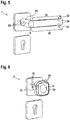
- Fig. 5 shows a possible embodiment of the door operator 7 as a door handle.
- This door handle comprises a handle area 30 which can be operated with one hand by a user and can be pressed down.
- the grip area 30 is connected to the handle follower 10 via a connection area 35.
- the trigger element 6 is in a position of the door operator 7 at which the trigger element 6 can be pressed by the thumb of the user.
- the release element 6 is located here at the transition from the grip area 30 to the connection area 35.
- FIG. 5 shows the use of lighting means 34 on the upper edge 32 and on the lower edge 33 of the grip area 30.
- a length 31 of the handle area 30 when the door operator 7 is designed as a door handle is selected such that the handle area 30 can only be operated by one hand.
- Fig. 6 shows an alternative embodiment of the door operator 7 as a door knob.
- a corresponding handle area 30 is connected to the door, possibly with the handle follower 10, via the connection area 35.
- Illuminants 34 are arranged around the handle area 30 of the door knob.
- the push-button release element 6 is located in the middle of the doorknob.
Landscapes
- Business, Economics & Management (AREA)
- Emergency Management (AREA)
- Physics & Mathematics (AREA)
- Electromagnetism (AREA)
- Lock And Its Accessories (AREA)
Description
- Die Erfindung betrifft ein Sicherheitssystem zur Fluchtwegsicherung und eine Tür mit dem Sicherheitssystem.
- Sicherheitssysteme mit einem Nottaster zur Fluchtwegsicherung sind bekannt. Bei einer Betätigung des Nottasters wird eine Türverriegelung entriegelt, so dass ein Benutzer im Gefahrenfall fliehen kann. Aus der
EP 2 725 172 A2 ist es bekannt, einen Nottaster und eine Türverriegelung über ein Bussystem miteinander zu verbinden. - Es ist Aufgabe der vorliegenden Erfindung, ein Sicherheitssystem zur Verfügung zu stellen, das bei einfachem Aufbau eine sichere Fluchtwegsicherung an einer Türe ermöglicht.
- Diese Aufgabe wird durch ein Sicherheitssystem gemäß dem unabhängigen Anspruch 1 gelöst. Vorteilhafte Weiterbildungen des Sicherheitssystems sind in den abhängigen Ansprüchen, der Beschreibung und in den Figuren angegeben.
- Somit wird die Aufgabe gelöst durch ein Sicherheitssystem zur Fluchtwegsicherung. Das Sicherheitssystem umfasst einen Türbetätiger. Der Türbetätiger ist beispielsweise ausgebildet als Türdrücker oder Türknauf und dient zum manuellen, mechanischen Öffnen einer drehbar oder verschiebbar anordenbaren Tür. Des Weiteren umfasst das Sicherheitssystem eine elektrische Türverriegelung zum Verriegeln der Tür. Diese Türverriegelung wird im Folgenden noch detaillierter erläutert. Darüber hinaus umfasst das Sicherheitssystem ein Auslöseelement. Das Auslöseelement kann durch einen Benutzer betätigt werden, wodurch sich die Türverriegelung entriegelt und somit der Fluchtweg freigegeben wird. Dieses Auslöseelement ist in dem Türbetätiger integriert. Das Auslöseelement befindet sich somit nicht am Türrahmen oder an der Wand neben dem Türrahmen, sondern im Türbetätiger, also in dem Element, das vom Benutzer ohnehin zum Öffnen der Tür gegriffen wird. Dadurch ist es insbesondere möglich, dass der Benutzer mit nur einer Hand und im Wesentlichen nur einer Bewegung sowohl das manuelle Öffnen der Tür als auch gleichzeitig das Betätigen des Auslöseelements veranlasst. Dadurch ergibt sich eine sehr intuitive Benutzung des Fluchtweges.
- Das Auslöseelement umfasst vorzugsweise ein Betätigungselement. In Folge einer Betätigung des Betätigungselements kann die Türverriegelung zur Entriegelung angesteuert werden. Das Auslöseelement ist bevorzugt als ein Nottaster ausgebildet. In diesem Fall entspricht ein Betätigungselement des Auslöseelements dem Betätigungselement des Nottasters.
- Als Verriegelung wird die Überführung der Türverriegelung in einen verriegelten Zustand verstanden. Als Entriegelung wird die Überführung der Türverrieglung in einen entriegelten Zustand verstanden.
- Die Türverriegelung kann z. B. elektromechanisch oder rein elektromagnetisch ausgebildet sein. Die Türverriegelung umfasst z. B. zumindest eine Spule. Eine Ansteuerung der Türverriegelung zur Verriegelung oder Entriegelung kann insbesondere in einem Ab- oder Anschalten einer elektrischen Stromversorgung realisiert sein. Die elektrische Stromversorgung kann zur Versorgung der Spule mit elektrischem Strom dienen.
- Eine mögliche Türverriegelung (auch: Verriegelungsmechanismus) ist beispielhaft in der
DE 10 050 111 C1 beschrieben. Im entriegelten Zustand wirken z. B. keine magnetischen Kräfte auf die Tür. In dem verriegelten Zustand wirken z. B. magnetische Kräfte auf eine Tür. - Eine elektromechanische Türverriegelung weist im verriegelten Zustand eine mechanische Verbindung zur Tür auf. Im entriegelten Zustand ist die mechanische Verbindung aufhebbar oder aufgehoben.
- So kann die elektromechanische Türverriegelung z. B. ein Riegelelement, d. h. einen Riegel oder eine Türfalle, aufweisen, das sich in dem entriegelten Zustand der Türverriegelung in einer zurückgezogenen Position befindet. In der zurückgezogenen Position befindet sich das Riegelelement außer Eingriff mit der Tür. In dem verriegelten Zustand befindet sich das Riegelelement im Eingriff mit der Tür.
- In einer weiteren Alternative einer elektromechanischen Türverriegelung ist die Türverriegelung nach Art eines Türöffners aufgebaut. D. h. der Verriegelungsmechanismus umfasst ein Fallenelement. Im verriegelten Zustand der Türverriegelung befindet sich eine Türfalle der Tür im Eingriff mit der Türverriegelung. Im entriegelten Zustand gibt das Fallenelement die Türfalle derart frei, dass die Türfalle, insbesondere durch Druck auf die Tür, außer Eingriff mit der Türverriegelung gelangen kann.
- Bevorzugt führt ein Abschalten der elektrischen Stromversorgung zu einem entriegelten Zustand der Türverriegelung. Somit wird die Ansteuerung der Türverriegelung zur Entriegelung der Türverriegelung durch ein Abschalten der elektrischen Stromversorgung realisiert.
- Bevorzugt führt ein Anschalten der elektrischen Stromversorgung zu einem verriegelten Zustand der Türverriegelung. Somit wird die Ansteuerung der Türverriegelung zur Verriegelung durch ein Anschalten der elektrischen Stromversorgung realisiert.
- Der "Benutzer" kann jede Person sein, die das Sicherheitssystem benutzt. Ein Benutzer kann z. B. ein Gast sein, der durch die durch das Sicherheitssystem gesicherte Tür fliehen will.
- Das Sicherheitssystem dient insbesondere zur Fluchtwegsicherung. Das Sicherheitssystem dient somit zur Freigabe des Fluchtwegs. D. h. die Betätigung des Auslöseelements führt ohne eine Authentifizierung des Benutzers zu einer Entriegelung. Die Entriegelung kann unmittelbar oder zeitverzögert erfolgen.
- Das Auslöseelement kann eine Ansteuerung der Türverriegelung zur Entriegelung veranlassen. Unter dem Veranlassen einer Ansteuerung wird insbesondere das Senden einer Nachricht über ein Bussystem verstanden, die eine Information und/oder einen Befehl enthält, die den unmittelbaren oder mittelbaren Empfänger der Nachricht veranlasst, die Ansteuerung vorzunehmen. Der Sender der Nachricht initiiert die Ansteuerung. Somit wird unter Veranlassen einer Ansteuerung eine indirekte Ansteuerung verstanden. So kann z. B. das Auslöseelement eine Nachricht über ein Bussystem an eine Türverriegelungssteuerung senden, woraufhin die Türverriegelungssteuerung die Türverriegelung zur Entriegelung ansteuert. Das Auslöseelement kann insbesondere zeitverzögert die Entriegelung der Türverriegelung veranlassen.
- Vorzugsweise ist vorgesehen, dass der Türbetätiger ausschließlich zur einhändigen Bedienung ausgebildet ist.
- Solch ein Türbetätiger zur ausschließlich einhändigen Bedienung ist insbesondere ein Türdrücker oder Türknauf, jedoch keine Panikstange.
- Bei der Ausbildung des Türbetätigers als Türdrücker (auch: Türklinke) ist vorzugsweise vorgesehen, dass der Türdrücker einen Griffbereich umfasst. Dieser Griffbereich ist von einer Hand des Benutzers greifbar. Das Auslöseelement ist dabei so angeordnet, dass es durch den Daumen der greifenden Hand gedrückt werden kann. Besonders bevorzugt umfasst der Türdrücker neben dem Griffbereich auch einen Verbindungsbereich, der den Griffbereich mit dem Türblatt bzw. dem Schloss verbindet.
- Des Weiteren ist bevorzugt vorgesehen, dass der Griffbereich max. 20 cm, insbesondere max. 15 cm, lang ist und somit lediglich mit einer Hand betätigt werden kann.
- Als Alternative zum Türdrücker kann der Türbetätiger z.B. als Türknauf ausgebildet sein. Der Türknauf kann drehbar sein, wobei durch das Drehen die Falle zurückgezogen wird. Alternativ kann der Türknauf auch fest sein und lediglich vom Benutzer zum Aufdrücken der Türe genutzt werden.
- Des Weiteren ist kann der Türbetätiger nicht nur zur einhändigen Bedienung ausgebildet sein und ist dabei beispielsweise als eine Panikstange ausgebildet.
- Der Türbetätiger umfasst vorzugsweise ein in den Türbetätiger integriertes Leuchtmittel, beispielsweise ein oder mehrere LEDs. Mit dem Leuchtmittel kann ein Zustand der Türverriegelung angezeigt werden. Das Leuchtmittel kann vollständig oder teilweise in das Auslöseelement integriert sein. Allerdings ist es auch möglich, das Leuchtmittel unabhängig vom Auslöseelement in den Türbetätiger zu integrieren.
- Bei einer Ausgestaltung des Türbetätigers als Türdrücker ist insbesondere vorgesehen, dass das Leuchtmittel entlang des Griffbereichs, vorzugsweise an einer Oberkante und/oder Unterkante des Griffbereichs, angeordnet ist.
- Des Weiteren ist bevorzugt vorgesehen, dass im Türbetätiger eine von Blinden ertastbare Nachricht angeordnet ist. Diese Nachricht ist insbesondere in Brailleschrift geschrieben. Die Nachricht gibt einen Hinweis auf die Anordnung des Auslöseelements im Türbetätiger.
- Das Sicherheitssystem umfasst erfindungsgemäß ein Schloss mit Schlosskasten. Das Schloss ist insbesondere in das Türblatt integriert. Der oben beschriebene Türbetätiger dient vorzugsweise zum Betätigen einer Falle des Schlosses.
- Das Schloss ist vorzugsweise als ein selbstverriegelndes Panikschloss ausgebildet.
- Das Schloss kann einen Riegel und/oder eine Falle umfassen.
- Die Türverriegelung kann in das Schloss integriert sein. Bevorzugt ist die Türverriegelung jedoch als separate Baugruppe unabhängig vom Schloss angeordnet.
- Erfindungsgemäß ist vorgesehen, dass ein strom- und/oder datenführender Anschluss des Auslöseelements über das Schloss, insbesondere über den Schlosskasten, erfolgt.
- Das Schloss umfasst vorzugsweise eine Schlosselektrik im Schlosskasten. Die Schlosselektrik kann einen Prozessor/Controller umfassen. Die Schlosselektrik kann insbesondere einer Schlosselektronik entsprechen.
- Die Schlosselektrik kann zumindest einen Sensor umfassen. Der Sensor kann insbesondere als Schalt- oder Reedkontakt ausgebildet sein. Der Sensor kann zur Detektion zumindest einer Stellung eines mechanischen Elements des Schlosses dienen. Das mechanische Element kann als der Riegel, die Falle, eine Steuerfalle und/oder als ein Schieber ausgebildet sein.
- Die Schlosselektrik kann zusätzlich oder alternativ einen elektromechanischen Aktuator umfassen. Diese Schlosselektrik ist insbesondere ansteuerbar, wobei insbesondere der Riegel und/oder die Falle des Schlosses durch die ansteuerbare Schlosselektrik betätigbar sind. Der elektromechanische Aktuator ist insbesondere ein Elektromotor oder Elektromagnet ausgebildet. Der Sensor kann ausgebildet sein, um die Stellung eines Schlossgetriebe, das sich an den Aktuator anschließt, zu detektieren.
- Vorzugsweise ist vorgesehen, dass am Schlosskasten ein gemeinsamer Steckverbinder ausgebildet ist. An den Steckverbinder kann ein Kabelstrang angeschlossen werden. Über diesen Steckverbinder wird somit gleichzeitig die Schlosselektrik und das Auslöseelement angeschlossen.
- Insbesondere ist vorgesehen, dass ein gemeinsamer Kabelstrang mit mehreren Kabeln durch die Tür geführt wird. Die Führung des Kabelstrangs erfolgt insbesondere im Inneren des Türblatts. Die Schlosselektrik und das Auslöseelement werden an Kabeln dieses gemeinsamen Kabelstrangs angeschlossen. Insbesondere erfolgt dies über den oben beschriebenen gemeinsamen Steckverbinder.
- Der Kabelstrang führt vorzugsweise vom Türblatt über den Rahmen nach außen, beispielsweise zu einem Steuergerät und/oder einer Wacheinrichtung, von der aus aus der Ferne das Schloss, die Türverriegelung und/oder das Auslöseelement überwachbar sind. Die Wacheinrichtung kann Teil des Sicherheitssystems sein.
- Wird auf den oben beschriebenen Steckverbinder am Schlosskasten verzichtet, so führt der Kabelstrang vorzugsweise in das Innere des Schlosskastens und ist im Inneren des Schlosskastens direkt an die Schlosselektrik und an die Auslöseelementleitungen angeschlossen.
- Des Weiteren ist vorzugsweise vorgesehen, dass die Schlosselektrik und das Auslöseelement zur Datenübertragung an unterschiedliche Kabel des gemeinsamen Kabelstrangs angeschlossen sind. Dadurch ist eine unabhängige analoge oder digitale Ansteuerung von Schlosselektrik und Auslöseelement möglich.
- Alternativ hierzu ist es möglich, dass die Schlosselektrik und das Auslöseelement zur Datenübertragung an denselben Bus und somit insbesondere an dieselben Kabel angeschlossen sind. Dadurch ist eine individuelle digitale Ansteuerung von Schlosselektrik und Auslöseelement möglich.
- Des Weiteren ist bevorzugt vorgesehen, dass durch den Schlosskasten zumindest eine Auslöseelementleitung geführt ist. Die Auslöseelementleitung dient zur Daten- und/oder Stromübertragung mit dem Auslöseelement. Die Auslöseelementleitung ist insbesondere mit dem beschriebenen Steckverbinder verbunden bzw. an den Steckverbinder angeschlossen. Insbesondere sind mehrere Auslöseelementleitungen vorgesehen, die durch den Schlosskasten hindurch geführt sind.
- Die jeweilige Auslöseelementleitung geht insbesondere vom Auslöseelement bis in den Schlosskasten.
- Die Erfindung umfasst des Weiteren eine Tür mit dem beschriebenen Sicherheitssystem.
- Die Erfindung wird nachfolgend anhand eines Ausführungsbeispiels näher erläutert. Technische Merkmale mit gleicher Funktion sind in den Figuren mit identischen Bezugszeichen versehen. Es zeigen:
- Fig. 1 und 2
- zwei schematische Ansichten des erfindungsgemäßen Sicherheitssystems gemäß dem Ausführungsbeispiel,
- Fig. 3
- ein Schloss des erfindungsgemäßen Sicherheitssystems gemäß dem Ausführungsbeispiel mit einer ersten Anschlussvariante,
- Fig. 4
- ein Schloss des erfindungsgemäßen Sicherheitssystems gemäß dem Ausführungsbeispiel mit einer zweiten Anschlussvariante,
- Fig. 5
- einen Türbetätiger des erfindungsgemäßen Sicherheitssystems gemäß dem Ausführungsbeispiel, ausgebildet als Türdrücker, und
- Fig. 6
- einen Türbetätiger des erfindungsgemäßen Sicherheitssystems gemäß dem Ausführungsbeispiel, ausgebildet als Türknauf.
-
Fig. 1 und2 zeigen eine Übersicht des Sicherheitssystems 1. Das Sicherheitssystem 1 kommt an einer Tür 2 zur Anwendung. Die Tür 2 ist in einem Rahmen 3 drehbar angeordnet. - Wie die schematische Darstellung in
Fig. 2 zeigt, befindet sich im Inneren der Tür 2 ein Schloss 8 des Sicherheitssystems 1. An eine Drückernuss 10 des Schlosses 8 ist ein Türbetätiger 7 angeschlossen. Diesen Türbetätiger 7 zeigt dieFigur 1 . - Des Weiteren umfasst das Sicherheitssystem 1 eine Türverriegelung 5, die die Tür 2 im verriegelten Zustand elektromechanisch oder elektromagnetisch mit dem Rahmen 3 verbindet.
- Im gezeigten Ausführungsbeispiel ist das Schloss 8 über einen Kabelstrang 17 mit einem Steuergerät 4 verbunden. Des Weiteren ist auch die Türverriegelung 5 mit dem Steuergerät 4 verbunden. Im Türbetätiger 7 befindet sich ein Auslöseelement 6. Dieses Auslöseelement 6 ist datenübertragend über das Schloss 8 und den Kabelstrang 17 mit dem Steuergerät 4 verbunden. Dadurch ist es möglich, durch Betätigen des Auslöseelements 6 die Türverriegelung 5 anzusteuern, insbesondere zu entriegeln.
-
Fig. 3 zeigt das Schloss 8. Das Schloss 8 umfasst einen Schlosskasten 9. Aus diesem Schlosskasten 9 ragen Fallen 11 und ein Riegel 12. Die Fallen 11 und/oder der Riegel 12 sind über einen Schlossmotor 13 betätigbar. Dadurch bilden die Fallen 11, der Riegel 12 und der Schlossmotor 13 zusammen die Schlosselektrik. - Am Schlosskasten 9 befindet sich ein Steckverbinder 14. An diesen Steckverbinder 14 kann der Kabelstrang 17 angesteckt werden. Im gezeigten Beispiel umfasst der Kabelstrang 17 zwei Kabel 18 zur Datenübertragung. Zusätzlich kann der Kabelstrang 17 weitere Kabel zur Datenübertragung und/oder stromführende Kabel umfassen.
- Die Darstellung mit den beiden Kabeln 18 zur Datenübertragung soll den Anschluss der Schlosselektrik 11, 12, 13 und des Auslöseelements 6 an ein und denselben Bus verdeutlichen. Wie die schematische Darstellung in
Fig. 3 zeigt, führen die beiden Kabel 18 im Inneren des Schlosskastens 9 zu einer Busschnittstelle 19. An diese Busschnittstelle 19 ist die Schlosselektrik 11, 12, 13 über Schlossleitungen 16 angeschlossen. Des Weiteren führen zu der Busschnittstelle 19 Auslöseelementleitungen 15. - Diese Auslöseelementleitungen 15 dienen zur strom- und/oder datenführenden Anbindung des Auslöseelements 6 im Türbetätiger 7. Im gezeigten Beispiel, werden die Auslöseelementleitungen 15 vom Schlosskasten 9 durch die Drückernuss 10 hindurch nach außen geführt. Allerdings ist auch eine andere Kabelführung denkbar.
-
Fig. 4 zeigt ebenfalls das Schloss 8 in schematischer Darstellung.Fig. 4 verdeutlicht, dass es auch möglich ist, ohne einem gemeinsamen Bussystem über das Schloss 8 sowohl die Schlosselektrik 11, 12, 13 als auch das Auslöseelement 6 daten- und/oder stromführend anzuschließen. So verdeutlichtFig. 4 , dass der Kabelstrang 17 zumindest vier Kabel 18 umfasst. Diese Kabel 18 sind, vorzugsweise über den Steckverbinder 14, im Inneren des Schlosskastens 9 mit den Auslöseelementleitungen 15 und mit den Schlossleitungen 16 verbunden. -
Fig. 5 zeigt eine mögliche Ausgestaltung des Türbetätigers 7 als Türdrücker. Dieser Türdrücker umfasst einen Griffbereich 30, der einhändig von einem Benutzer bedient und nach unten gedrückt werden kann. Der Griffbereich 30 ist über einen Verbindungsbereich 35 mit der Drückernuss 10 verbunden. - Wie die Darstellung in
Fig. 5 zeigt, befindet sich das Auslöseelement 6 an einer Position des Türbetätigers 7, an der das Auslöseelement 6 vom Daumen des Benutzers gedrückt werden kann. Insbesondere befindet sich hier das Auslöseelement 6 am Übergang des Griffbereichs 30 in den Verbindungsbereich 35. - Ferner zeigt
Fig. 5 die Verwendung von Leuchtmitteln 34 an der Oberkante 32 und an der Unterkante 33 des Griffbereichs 30. - Eine Länge 31 des Griffbereichs 30 bei der Ausbildung des Türbetätigers 7 als Türdrücker ist dabei so gewählt, dass der Griffbereich 30 lediglich von einer Hand zu bedienen ist.
-
Fig. 6 zeigt eine alternative Ausgestaltung des Türbetätigers 7 als Türknauf. Auch hier ist ein entsprechender Griffbereich 30 über den Verbindungsbereich 35 mit der Tür, gegebenenfalls mit der Drückernuss 10, verbunden. - Rund um den Griffbereich 30 des Türknaufs sind Leuchtmittel 34 angeordnet. In der Mitte des Türknaufs befindet sich das drückbare Auslöseelement 6.
-
- 1
- Sicherheitssystem
- 2
- Tür
- 3
- Rahmen
- 4
- Steuergerät
- 5
- Türverriegelung
- 6
- Auslöseelement
- 7
- Türbetätiger
- 8
- Schloss
- 9
- Schlosskasten
- 10
- Drückernuss
- 11
- Fallen
- 12
- Riegel
- 13
- Schlossmotor
- 14
- Steckverbinder
- 15
- Auslöseelementleitungen
- 16
- Schlossleitungen
- 17
- Kabelstrang
- 18
- Kabel
- 19
- Busschnittstelle
- 30
- Griffbereich
- 31
- Länge des Griffbereichs
- 32
- Oberkante
- 33
- Unterkante
- 34
- Leuchtmittel
- 35
- Verbindungsbereich
Claims (15)
- Sicherheitssystem (1) zur Fluchtwegsicherung, umfassend:• einen Türbetätiger (7) zum manuellen, mechanischen Öffnen einer drehbar oder verschiebbar anordenbaren Tür (2),• eine elektrische Türverriegelung (5) zum Verriegeln der Tür (2), und• ein Auslöseelement (6), insbesondere einen Nottaster (6), zum Entriegeln der Türverriegelung (5),• wobei das Auslöseelement (6) in dem Türbetätiger (7) integriert ist,• wobei das Sicherheitssystem ein Schloss (8) mit Schlosskasten (9) umfasst dadurch gekennzeichnet, dass ein strom- und/oder datenführender Anschluss des Auslöseelements (6) über das Schloss (8) erfolgt.
- Sicherheitssystem nach Anspruch 1, wobei der Türbetätiger (7) als Türdrücker ausgebildet ist.
- Sicherheitssystem nach Anspruch 1 oder 2, wobei der Türbetätiger (7) als Türdrücker ausgebildet ist, wobei der Türdrücker einen durch eine Hand greifbaren Griffbereich (30) umfasst, und wobei das Auslöseelement (6) zum Drücken durch einen Daumen einer den Griffbereich (30) greifenden Hand angeordnet ist.
- Sicherheitssystem nach Anspruch 1, wobei der Türbetätiger (7) als Türknauf ausgebildet ist.
- Sicherheitssystem nach einem der Ansprüche 1 bis 4, wobei der Türbetätiger (7) zumindest ein integriertes Leuchtmittel (34) zur Anzeige einer Verriegelung und/oder Entriegelung der Tür (2) aufweist.
- Sicherheitssystem nach Anspruch 5, wobei sich das Leuchtmittel (34) entlang des Griffbereichs (30) des als Türdrücker ausgebildeten Türbetätigers (7), vorzugsweise an einer Oberkante (32) und/oder Unterkante (33) des Griffbereichs (30), erstreckt.
- Sicherheitssystem nach einem der Ansprüche 1 bis 6, wobei im Türbetätiger (7) eine von Blinden ertastbare Nachricht angeordnet ist, wobei die Nachricht einen Hinweis auf die Anordnung des Auslöseelements (6) im Türbetätiger (7) gibt.
- Sicherheitssystem nach einem der vorhergehenden Ansprüche, wobei das Schloss (8) als ein selbstverriegelndes Panikschloss ausgebildet ist und/oder wobei der strom- und/oder datenführender Anschluss des Auslöseelements (6) über den Schlosskasten (9) erfolgt.
- Sicherheitssystem nach Anspruch 8, wobei das Schloss (8) eine Schlosselektrik (11, 12, 13) im Schlosskasten (9) umfasst.
- Sicherheitssystem nach Anspruch 9, wobei am Schlosskasten (9) ein gemeinsamer Steckverbinder (14) des Schlosses (8) zum gleichzeitigen Anschließen der Schlosselektrik (11, 12, 13) und des Auslöseelements (6) angeordnet ist.
- Sicherheitssystem nach einem der Ansprüche 9 oder 10, wobei ein gemeinsamer Kabelstrang (17) mit mehreren Kabeln (18) zum Führen durch die Tür (2), vorzugsweise durch das Inneren der Tür (2), vorgesehen ist, wobei die Schlosselektrik (11, 12, 13) und das Auslöseelement (6) an Kabeln (18) des gemeinsamen Kabelstrangs (17) angeschlossen sind.
- Sicherheitssystem nach Anspruch 11, wobei die Schlosselektrik (11, 12, 13) und das Auslöseelement (6) zur Datenübertragung an unterschiedliche Kabel (18) des gemeinsamen Kabelstrangs (17) angeschlossen sind.
- Sicherheitssystem nach einem der Ansprüche 9 bis 12, wobei die Schlosselektrik (11, 12, 13) und das Auslöseelement (6) zur Datenübertragung an denselben Bus angeschlossen sind.
- Sicherheitssystem nach einem der Ansprüche 8 bis 13, wobei zumindest eine Auslöseelementleitung (15) zur Daten- und/oder Stromübertragung mit dem Auslöseelement (6) durch den Schlosskasten (9) geführt ist, wobei die Auslöseelementleitung (15) insbesondere an dem Steckverbinder (14) angeschlossen ist.
- Tür (2) mit einem Sicherheitssystem (1) nach einem der vorhergehenden Ansprüche.
Applications Claiming Priority (1)
| Application Number | Priority Date | Filing Date | Title |
|---|---|---|---|
| DE102018104295.7A DE102018104295A1 (de) | 2018-02-26 | 2018-02-26 | Sicherheitssystem zur Fluchtwegsicherung |
Publications (2)
| Publication Number | Publication Date |
|---|---|
| EP3530848A1 EP3530848A1 (de) | 2019-08-28 |
| EP3530848B1 true EP3530848B1 (de) | 2021-06-23 |
Family
ID=65365770
Family Applications (1)
| Application Number | Title | Priority Date | Filing Date |
|---|---|---|---|
| EP19151295.3A Active EP3530848B1 (de) | 2018-02-26 | 2019-01-10 | Sicherheitssystem zur fluchtwegsicherung |
Country Status (2)
| Country | Link |
|---|---|
| EP (1) | EP3530848B1 (de) |
| DE (1) | DE102018104295A1 (de) |
Families Citing this family (2)
| Publication number | Priority date | Publication date | Assignee | Title |
|---|---|---|---|---|
| CN116917592A (zh) | 2021-02-12 | 2023-10-20 | 麦森尼特公司 | 具有布线在门和外门框内以与电气设备连接的线束的门系统 |
| DE102024107684A1 (de) * | 2024-03-18 | 2025-09-18 | Assa Abloy Sicherheitstechnik Gmbh | Schloss für eine Tür mit schaltbarer Schnittstelle |
Citations (15)
| Publication number | Priority date | Publication date | Assignee | Title |
|---|---|---|---|---|
| DE1608624U (de) | 1950-03-30 | 1950-06-22 | Detmar Dr Med Schaefer | Signalanlage, insbesondere fuer ladentueren. |
| DE19531323A1 (de) | 1994-10-15 | 1996-04-18 | Geze Gmbh & Co | Ein Diagnose- und/oder Überwachungsverfahren und eine Sicherheitseinrichtung zur Durchführung des Verfahrens für mindestens eine Tür, vorzugsweise in Flucht- und Rettungswegen |
| DE19625237A1 (de) | 1996-06-24 | 1998-01-02 | Geze Gmbh & Co | Vernetztes RWS |
| DE19909953A1 (de) | 1999-03-06 | 2000-09-07 | Geze Glas Design Gmbh | Sicherungs- und Überwachungseinrichtung |
| DE10118120C1 (de) | 2001-04-11 | 2002-12-12 | Insta Elektro Gmbh | Beleuchtungssystem für Handhaben |
| DE20220013U1 (de) | 2001-12-31 | 2003-04-03 | Bonnet, Gregor, 64287 Darmstadt | Türgriff/Schalter |
| DE102004057114B3 (de) | 2004-11-26 | 2006-08-03 | Beckmann, Dieter, Dipl.-Ing. | Drückergarnitur für Feuerschutztüren |
| DE102005000008A1 (de) | 2005-02-04 | 2006-08-10 | Aug. Winkhaus Gmbh & Co. Kg | Antriebseinrichtung für einen Treibstangenbeschlag |
| DE102007007015B3 (de) | 2007-02-08 | 2008-03-27 | Karcher Gmbh | Türgriff |
| DE202008004789U1 (de) | 2008-04-04 | 2008-07-17 | Moser-Metius, Jörg | Betätigungsvorrichtung für eine Tür |
| JP2008184739A (ja) | 2007-01-26 | 2008-08-14 | Miwa Lock Co Ltd | 電気錠用取手及び該取手を用いた電気錠システム |
| EP2284338A2 (de) | 2009-08-10 | 2011-02-16 | BKS GmbH | Elektrisches Verriegelungssystem für Tür-Panikverschluss und Panikverschluss-Druckstange |
| EP2725172A2 (de) | 2012-10-25 | 2014-04-30 | ASSA ABLOY Sicherheitstechnik GmbH | Verfahren zum Betreiben einer Rettungswegvorrichtung sowie Rettungsweganordnung |
| EP2998490A1 (de) | 2014-09-22 | 2016-03-23 | ASSA ABLOY Sicherheitstechnik GmbH | Panikdruckstange mit nottaste und verschiebbarem display |
| DE102015108026A1 (de) | 2015-05-21 | 2016-11-24 | Carl Fuhr Gmbh & Co. Kg | Schließanlage und Verfahren zum Betrieb einer Schließanlage für eine Gebäudetür |
Family Cites Families (1)
| Publication number | Priority date | Publication date | Assignee | Title |
|---|---|---|---|---|
| DE10050111C1 (de) | 2000-10-09 | 2002-08-08 | Dorma Gmbh & Co Kg | Verriegelungsvorrichtung |
-
2018
- 2018-02-26 DE DE102018104295.7A patent/DE102018104295A1/de active Pending
-
2019
- 2019-01-10 EP EP19151295.3A patent/EP3530848B1/de active Active
Patent Citations (15)
| Publication number | Priority date | Publication date | Assignee | Title |
|---|---|---|---|---|
| DE1608624U (de) | 1950-03-30 | 1950-06-22 | Detmar Dr Med Schaefer | Signalanlage, insbesondere fuer ladentueren. |
| DE19531323A1 (de) | 1994-10-15 | 1996-04-18 | Geze Gmbh & Co | Ein Diagnose- und/oder Überwachungsverfahren und eine Sicherheitseinrichtung zur Durchführung des Verfahrens für mindestens eine Tür, vorzugsweise in Flucht- und Rettungswegen |
| DE19625237A1 (de) | 1996-06-24 | 1998-01-02 | Geze Gmbh & Co | Vernetztes RWS |
| DE19909953A1 (de) | 1999-03-06 | 2000-09-07 | Geze Glas Design Gmbh | Sicherungs- und Überwachungseinrichtung |
| DE10118120C1 (de) | 2001-04-11 | 2002-12-12 | Insta Elektro Gmbh | Beleuchtungssystem für Handhaben |
| DE20220013U1 (de) | 2001-12-31 | 2003-04-03 | Bonnet, Gregor, 64287 Darmstadt | Türgriff/Schalter |
| DE102004057114B3 (de) | 2004-11-26 | 2006-08-03 | Beckmann, Dieter, Dipl.-Ing. | Drückergarnitur für Feuerschutztüren |
| DE102005000008A1 (de) | 2005-02-04 | 2006-08-10 | Aug. Winkhaus Gmbh & Co. Kg | Antriebseinrichtung für einen Treibstangenbeschlag |
| JP2008184739A (ja) | 2007-01-26 | 2008-08-14 | Miwa Lock Co Ltd | 電気錠用取手及び該取手を用いた電気錠システム |
| DE102007007015B3 (de) | 2007-02-08 | 2008-03-27 | Karcher Gmbh | Türgriff |
| DE202008004789U1 (de) | 2008-04-04 | 2008-07-17 | Moser-Metius, Jörg | Betätigungsvorrichtung für eine Tür |
| EP2284338A2 (de) | 2009-08-10 | 2011-02-16 | BKS GmbH | Elektrisches Verriegelungssystem für Tür-Panikverschluss und Panikverschluss-Druckstange |
| EP2725172A2 (de) | 2012-10-25 | 2014-04-30 | ASSA ABLOY Sicherheitstechnik GmbH | Verfahren zum Betreiben einer Rettungswegvorrichtung sowie Rettungsweganordnung |
| EP2998490A1 (de) | 2014-09-22 | 2016-03-23 | ASSA ABLOY Sicherheitstechnik GmbH | Panikdruckstange mit nottaste und verschiebbarem display |
| DE102015108026A1 (de) | 2015-05-21 | 2016-11-24 | Carl Fuhr Gmbh & Co. Kg | Schließanlage und Verfahren zum Betrieb einer Schließanlage für eine Gebäudetür |
Also Published As
| Publication number | Publication date |
|---|---|
| EP3530848A1 (de) | 2019-08-28 |
| DE102018104295A1 (de) | 2019-08-29 |
Similar Documents
| Publication | Publication Date | Title |
|---|---|---|
| EP1512814B2 (de) | Kraftfahrzeug-Türschliesssystem und Türgriff | |
| EP2354391B1 (de) | Kraftfahrzeugschließsystem | |
| EP2909404B1 (de) | Kraftfahrzeugtürschloss | |
| EP3303741B1 (de) | Kraftfahrzeugtürverschluss | |
| DE2847589A1 (de) | Sicherungseinrichtung fuer tueren o.dgl. an fahrzeugen, insbesondere kraftfahrzeugen | |
| EP1304433A1 (de) | Kraftfahrzeug-Türschloss mit voneinander getrennter Schliesseinheit und Steuereinheit | |
| DE102016103926A1 (de) | Vorrichtung zum Öffnen einer Tür oder Klappe an einem Kraftfahrzeug | |
| DE10360422A1 (de) | Kraftfahrzeug | |
| DE102015011468A1 (de) | Schließvorrichtung für eine Fahrzeugtür und ein Fahrzeug | |
| DE102015108739A1 (de) | Verfahren zur Steuerung eines Kraftfahrzeugtürverschlusses | |
| EP3530848B1 (de) | Sicherheitssystem zur fluchtwegsicherung | |
| EP1936075A2 (de) | Selbstverriegelndes, elektromechanisches Panikschloss | |
| EP2765261A2 (de) | Schließvorrichtung eines Gebäudes | |
| EP3728769A1 (de) | Kraftfahrzeugtürgriffanordnung mit notbetätigungshebel | |
| DE102008021979A1 (de) | Betätigungseinrichtung zur Entriegelung von Fahrzeugtüren | |
| EP1160398B1 (de) | Elektrisch betätigbares Schloss | |
| DE202010007509U1 (de) | Schloss und Tür, Fenster o.dgl. mit einem Schloss | |
| DE102004025097B4 (de) | Türaußengriff für ein Kraftfahrzeug | |
| DE102007042574A1 (de) | Panikschloss mit elektromotorisch angetriebener Falle | |
| DE10011563A1 (de) | Kraftfahrzeugschloß | |
| DE19832646C2 (de) | Vorrichtung zum Öffnen und Schließen eines Türschlosses | |
| DE943569C (de) | Fernbetaetigte Tuerverriegelungsanlage fuer Automobilc und andere Fahrzeuge | |
| EP0849423B1 (de) | Schliesseinrichtung | |
| DE60222216T2 (de) | Verriegelungsvorrichtung | |
| DE69712427T2 (de) | Kraftfahrzeug-Türschloss |
Legal Events
| Date | Code | Title | Description |
|---|---|---|---|
| PUAI | Public reference made under article 153(3) epc to a published international application that has entered the european phase |
Free format text: ORIGINAL CODE: 0009012 |
|
| STAA | Information on the status of an ep patent application or granted ep patent |
Free format text: STATUS: THE APPLICATION HAS BEEN PUBLISHED |
|
| AK | Designated contracting states |
Kind code of ref document: A1 Designated state(s): AL AT BE BG CH CY CZ DE DK EE ES FI FR GB GR HR HU IE IS IT LI LT LU LV MC MK MT NL NO PL PT RO RS SE SI SK SM TR |
|
| AX | Request for extension of the european patent |
Extension state: BA ME |
|
| STAA | Information on the status of an ep patent application or granted ep patent |
Free format text: STATUS: REQUEST FOR EXAMINATION WAS MADE |
|
| 17P | Request for examination filed |
Effective date: 20200227 |
|
| RBV | Designated contracting states (corrected) |
Designated state(s): AL AT BE BG CH CY CZ DE DK EE ES FI FR GB GR HR HU IE IS IT LI LT LU LV MC MK MT NL NO PL PT RO RS SE SI SK SM TR |
|
| GRAP | Despatch of communication of intention to grant a patent |
Free format text: ORIGINAL CODE: EPIDOSNIGR1 |
|
| STAA | Information on the status of an ep patent application or granted ep patent |
Free format text: STATUS: GRANT OF PATENT IS INTENDED |
|
| RIC1 | Information provided on ipc code assigned before grant |
Ipc: E05B 17/00 20060101ALN20210113BHEP Ipc: E05B 17/10 20060101ALN20210113BHEP Ipc: E05B 1/00 20060101ALN20210113BHEP Ipc: E05B 47/02 20060101AFI20210113BHEP Ipc: E05B 63/00 20060101ALN20210113BHEP Ipc: E05B 47/00 20060101ALN20210113BHEP Ipc: E05B 65/10 20060101ALI20210113BHEP Ipc: E05C 19/16 20060101ALN20210113BHEP |
|
| INTG | Intention to grant announced |
Effective date: 20210203 |
|
| GRAS | Grant fee paid |
Free format text: ORIGINAL CODE: EPIDOSNIGR3 |
|
| GRAA | (expected) grant |
Free format text: ORIGINAL CODE: 0009210 |
|
| STAA | Information on the status of an ep patent application or granted ep patent |
Free format text: STATUS: THE PATENT HAS BEEN GRANTED |
|
| AK | Designated contracting states |
Kind code of ref document: B1 Designated state(s): AL AT BE BG CH CY CZ DE DK EE ES FI FR GB GR HR HU IE IS IT LI LT LU LV MC MK MT NL NO PL PT RO RS SE SI SK SM TR |
|
| REG | Reference to a national code |
Ref country code: GB Ref legal event code: FG4D Free format text: NOT ENGLISH |
|
| REG | Reference to a national code |
Ref country code: CH Ref legal event code: EP |
|
| REG | Reference to a national code |
Ref country code: DE Ref legal event code: R096 Ref document number: 502019001642 Country of ref document: DE Ref country code: AT Ref legal event code: REF Ref document number: 1404457 Country of ref document: AT Kind code of ref document: T Effective date: 20210715 |
|
| REG | Reference to a national code |
Ref country code: IE Ref legal event code: FG4D Free format text: LANGUAGE OF EP DOCUMENT: GERMAN |
|
| REG | Reference to a national code |
Ref country code: LT Ref legal event code: MG9D |
|
| PG25 | Lapsed in a contracting state [announced via postgrant information from national office to epo] |
Ref country code: BG Free format text: LAPSE BECAUSE OF FAILURE TO SUBMIT A TRANSLATION OF THE DESCRIPTION OR TO PAY THE FEE WITHIN THE PRESCRIBED TIME-LIMIT Effective date: 20210923 Ref country code: FI Free format text: LAPSE BECAUSE OF FAILURE TO SUBMIT A TRANSLATION OF THE DESCRIPTION OR TO PAY THE FEE WITHIN THE PRESCRIBED TIME-LIMIT Effective date: 20210623 Ref country code: HR Free format text: LAPSE BECAUSE OF FAILURE TO SUBMIT A TRANSLATION OF THE DESCRIPTION OR TO PAY THE FEE WITHIN THE PRESCRIBED TIME-LIMIT Effective date: 20210623 Ref country code: LT Free format text: LAPSE BECAUSE OF FAILURE TO SUBMIT A TRANSLATION OF THE DESCRIPTION OR TO PAY THE FEE WITHIN THE PRESCRIBED TIME-LIMIT Effective date: 20210623 |
|
| PG25 | Lapsed in a contracting state [announced via postgrant information from national office to epo] |
Ref country code: GR Free format text: LAPSE BECAUSE OF FAILURE TO SUBMIT A TRANSLATION OF THE DESCRIPTION OR TO PAY THE FEE WITHIN THE PRESCRIBED TIME-LIMIT Effective date: 20210924 Ref country code: LV Free format text: LAPSE BECAUSE OF FAILURE TO SUBMIT A TRANSLATION OF THE DESCRIPTION OR TO PAY THE FEE WITHIN THE PRESCRIBED TIME-LIMIT Effective date: 20210623 Ref country code: NO Free format text: LAPSE BECAUSE OF FAILURE TO SUBMIT A TRANSLATION OF THE DESCRIPTION OR TO PAY THE FEE WITHIN THE PRESCRIBED TIME-LIMIT Effective date: 20210923 Ref country code: RS Free format text: LAPSE BECAUSE OF FAILURE TO SUBMIT A TRANSLATION OF THE DESCRIPTION OR TO PAY THE FEE WITHIN THE PRESCRIBED TIME-LIMIT Effective date: 20210623 Ref country code: SE Free format text: LAPSE BECAUSE OF FAILURE TO SUBMIT A TRANSLATION OF THE DESCRIPTION OR TO PAY THE FEE WITHIN THE PRESCRIBED TIME-LIMIT Effective date: 20210623 |
|
| REG | Reference to a national code |
Ref country code: NL Ref legal event code: MP Effective date: 20210623 |
|
| PG25 | Lapsed in a contracting state [announced via postgrant information from national office to epo] |
Ref country code: SK Free format text: LAPSE BECAUSE OF FAILURE TO SUBMIT A TRANSLATION OF THE DESCRIPTION OR TO PAY THE FEE WITHIN THE PRESCRIBED TIME-LIMIT Effective date: 20210623 Ref country code: ES Free format text: LAPSE BECAUSE OF FAILURE TO SUBMIT A TRANSLATION OF THE DESCRIPTION OR TO PAY THE FEE WITHIN THE PRESCRIBED TIME-LIMIT Effective date: 20210623 Ref country code: EE Free format text: LAPSE BECAUSE OF FAILURE TO SUBMIT A TRANSLATION OF THE DESCRIPTION OR TO PAY THE FEE WITHIN THE PRESCRIBED TIME-LIMIT Effective date: 20210623 Ref country code: NL Free format text: LAPSE BECAUSE OF FAILURE TO SUBMIT A TRANSLATION OF THE DESCRIPTION OR TO PAY THE FEE WITHIN THE PRESCRIBED TIME-LIMIT Effective date: 20210623 Ref country code: PT Free format text: LAPSE BECAUSE OF FAILURE TO SUBMIT A TRANSLATION OF THE DESCRIPTION OR TO PAY THE FEE WITHIN THE PRESCRIBED TIME-LIMIT Effective date: 20211025 Ref country code: RO Free format text: LAPSE BECAUSE OF FAILURE TO SUBMIT A TRANSLATION OF THE DESCRIPTION OR TO PAY THE FEE WITHIN THE PRESCRIBED TIME-LIMIT Effective date: 20210623 Ref country code: SM Free format text: LAPSE BECAUSE OF FAILURE TO SUBMIT A TRANSLATION OF THE DESCRIPTION OR TO PAY THE FEE WITHIN THE PRESCRIBED TIME-LIMIT Effective date: 20210623 Ref country code: CZ Free format text: LAPSE BECAUSE OF FAILURE TO SUBMIT A TRANSLATION OF THE DESCRIPTION OR TO PAY THE FEE WITHIN THE PRESCRIBED TIME-LIMIT Effective date: 20210623 |
|
| REG | Reference to a national code |
Ref country code: DE Ref legal event code: R026 Ref document number: 502019001642 Country of ref document: DE |
|
| PG25 | Lapsed in a contracting state [announced via postgrant information from national office to epo] |
Ref country code: PL Free format text: LAPSE BECAUSE OF FAILURE TO SUBMIT A TRANSLATION OF THE DESCRIPTION OR TO PAY THE FEE WITHIN THE PRESCRIBED TIME-LIMIT Effective date: 20210623 |
|
| PLBI | Opposition filed |
Free format text: ORIGINAL CODE: 0009260 |
|
| PLAX | Notice of opposition and request to file observation + time limit sent |
Free format text: ORIGINAL CODE: EPIDOSNOBS2 |
|
| 26 | Opposition filed |
Opponent name: ASSA ABLOY SICHERHEITSTECHNIK GMBH Effective date: 20220223 |
|
| PG25 | Lapsed in a contracting state [announced via postgrant information from national office to epo] |
Ref country code: DK Free format text: LAPSE BECAUSE OF FAILURE TO SUBMIT A TRANSLATION OF THE DESCRIPTION OR TO PAY THE FEE WITHIN THE PRESCRIBED TIME-LIMIT Effective date: 20210623 |
|
| PG25 | Lapsed in a contracting state [announced via postgrant information from national office to epo] |
Ref country code: AL Free format text: LAPSE BECAUSE OF FAILURE TO SUBMIT A TRANSLATION OF THE DESCRIPTION OR TO PAY THE FEE WITHIN THE PRESCRIBED TIME-LIMIT Effective date: 20210623 |
|
| PG25 | Lapsed in a contracting state [announced via postgrant information from national office to epo] |
Ref country code: IT Free format text: LAPSE BECAUSE OF FAILURE TO SUBMIT A TRANSLATION OF THE DESCRIPTION OR TO PAY THE FEE WITHIN THE PRESCRIBED TIME-LIMIT Effective date: 20210623 |
|
| PLBB | Reply of patent proprietor to notice(s) of opposition received |
Free format text: ORIGINAL CODE: EPIDOSNOBS3 |
|
| PG25 | Lapsed in a contracting state [announced via postgrant information from national office to epo] |
Ref country code: MC Free format text: LAPSE BECAUSE OF FAILURE TO SUBMIT A TRANSLATION OF THE DESCRIPTION OR TO PAY THE FEE WITHIN THE PRESCRIBED TIME-LIMIT Effective date: 20210623 |
|
| REG | Reference to a national code |
Ref country code: BE Ref legal event code: MM Effective date: 20220131 |
|
| PG25 | Lapsed in a contracting state [announced via postgrant information from national office to epo] |
Ref country code: LU Free format text: LAPSE BECAUSE OF NON-PAYMENT OF DUE FEES Effective date: 20220110 |
|
| PG25 | Lapsed in a contracting state [announced via postgrant information from national office to epo] |
Ref country code: FR Free format text: LAPSE BECAUSE OF NON-PAYMENT OF DUE FEES Effective date: 20220131 Ref country code: BE Free format text: LAPSE BECAUSE OF NON-PAYMENT OF DUE FEES Effective date: 20220131 |
|
| PG25 | Lapsed in a contracting state [announced via postgrant information from national office to epo] |
Ref country code: IE Free format text: LAPSE BECAUSE OF NON-PAYMENT OF DUE FEES Effective date: 20220110 |
|
| GBPC | Gb: european patent ceased through non-payment of renewal fee |
Effective date: 20230110 |
|
| PG25 | Lapsed in a contracting state [announced via postgrant information from national office to epo] |
Ref country code: GB Free format text: LAPSE BECAUSE OF NON-PAYMENT OF DUE FEES Effective date: 20230110 |
|
| APBM | Appeal reference recorded |
Free format text: ORIGINAL CODE: EPIDOSNREFNO |
|
| APBP | Date of receipt of notice of appeal recorded |
Free format text: ORIGINAL CODE: EPIDOSNNOA2O |
|
| APAH | Appeal reference modified |
Free format text: ORIGINAL CODE: EPIDOSCREFNO |
|
| APAL | Date of receipt of statement of grounds of an appeal modified |
Free format text: ORIGINAL CODE: EPIDOSCNOA3O |
|
| APBQ | Date of receipt of statement of grounds of appeal recorded |
Free format text: ORIGINAL CODE: EPIDOSNNOA3O |
|
| PG25 | Lapsed in a contracting state [announced via postgrant information from national office to epo] |
Ref country code: MK Free format text: LAPSE BECAUSE OF FAILURE TO SUBMIT A TRANSLATION OF THE DESCRIPTION OR TO PAY THE FEE WITHIN THE PRESCRIBED TIME-LIMIT Effective date: 20210623 Ref country code: CY Free format text: LAPSE BECAUSE OF FAILURE TO SUBMIT A TRANSLATION OF THE DESCRIPTION OR TO PAY THE FEE WITHIN THE PRESCRIBED TIME-LIMIT Effective date: 20210623 |
|
| PG25 | Lapsed in a contracting state [announced via postgrant information from national office to epo] |
Ref country code: HU Free format text: LAPSE BECAUSE OF FAILURE TO SUBMIT A TRANSLATION OF THE DESCRIPTION OR TO PAY THE FEE WITHIN THE PRESCRIBED TIME-LIMIT; INVALID AB INITIO Effective date: 20190110 |
|
| PG25 | Lapsed in a contracting state [announced via postgrant information from national office to epo] |
Ref country code: TR Free format text: LAPSE BECAUSE OF FAILURE TO SUBMIT A TRANSLATION OF THE DESCRIPTION OR TO PAY THE FEE WITHIN THE PRESCRIBED TIME-LIMIT Effective date: 20210623 |
|
| PG25 | Lapsed in a contracting state [announced via postgrant information from national office to epo] |
Ref country code: MT Free format text: LAPSE BECAUSE OF FAILURE TO SUBMIT A TRANSLATION OF THE DESCRIPTION OR TO PAY THE FEE WITHIN THE PRESCRIBED TIME-LIMIT Effective date: 20210623 |
|
| APBU | Appeal procedure closed |
Free format text: ORIGINAL CODE: EPIDOSNNOA9O |
|
| REG | Reference to a national code |
Ref country code: CH Ref legal event code: U11 Free format text: ST27 STATUS EVENT CODE: U-0-0-U10-U11 (AS PROVIDED BY THE NATIONAL OFFICE) Effective date: 20260201 |
|
| PGFP | Annual fee paid to national office [announced via postgrant information from national office to epo] |
Ref country code: DE Payment date: 20260121 Year of fee payment: 8 |
|
| PGFP | Annual fee paid to national office [announced via postgrant information from national office to epo] |
Ref country code: AT Payment date: 20260122 Year of fee payment: 8 |
|
| PGFP | Annual fee paid to national office [announced via postgrant information from national office to epo] |
Ref country code: CH Payment date: 20260201 Year of fee payment: 8 |