EP3530873B1 - Dispositif adapté pour être exécuté sur une colonne de tubage dans un puits de forage - Google Patents
Dispositif adapté pour être exécuté sur une colonne de tubage dans un puits de forage Download PDFInfo
- Publication number
- EP3530873B1 EP3530873B1 EP18157788.3A EP18157788A EP3530873B1 EP 3530873 B1 EP3530873 B1 EP 3530873B1 EP 18157788 A EP18157788 A EP 18157788A EP 3530873 B1 EP3530873 B1 EP 3530873B1
- Authority
- EP
- European Patent Office
- Prior art keywords
- tubing string
- inlet
- fluid
- wellbore
- string
- Prior art date
- Legal status (The legal status is an assumption and is not a legal conclusion. Google has not performed a legal analysis and makes no representation as to the accuracy of the status listed.)
- Active
Links
Images

Classifications
-
- E—FIXED CONSTRUCTIONS
- E21—EARTH OR ROCK DRILLING; MINING
- E21B—EARTH OR ROCK DRILLING; OBTAINING OIL, GAS, WATER, SOLUBLE OR MELTABLE MATERIALS OR A SLURRY OF MINERALS FROM WELLS
- E21B34/00—Valve arrangements for boreholes or wells
- E21B34/06—Valve arrangements for boreholes or wells in wells
- E21B34/14—Valve arrangements for boreholes or wells in wells operated by movement of tools, e.g. sleeve valves operated by pistons or wire line tools
- E21B34/142—Valve arrangements for boreholes or wells in wells operated by movement of tools, e.g. sleeve valves operated by pistons or wire line tools unsupported or free-falling elements, e.g. balls, plugs, darts or pistons
-
- E—FIXED CONSTRUCTIONS
- E21—EARTH OR ROCK DRILLING; MINING
- E21B—EARTH OR ROCK DRILLING; OBTAINING OIL, GAS, WATER, SOLUBLE OR MELTABLE MATERIALS OR A SLURRY OF MINERALS FROM WELLS
- E21B33/00—Sealing or packing boreholes or wells
- E21B33/10—Sealing or packing boreholes or wells in the borehole
- E21B33/12—Packers; Plugs
- E21B33/128—Packers; Plugs with a member expanded radially by axial pressure
-
- E—FIXED CONSTRUCTIONS
- E21—EARTH OR ROCK DRILLING; MINING
- E21B—EARTH OR ROCK DRILLING; OBTAINING OIL, GAS, WATER, SOLUBLE OR MELTABLE MATERIALS OR A SLURRY OF MINERALS FROM WELLS
- E21B34/00—Valve arrangements for boreholes or wells
- E21B34/06—Valve arrangements for boreholes or wells in wells
- E21B34/063—Valve or closure with destructible element, e.g. frangible disc
-
- E—FIXED CONSTRUCTIONS
- E21—EARTH OR ROCK DRILLING; MINING
- E21B—EARTH OR ROCK DRILLING; OBTAINING OIL, GAS, WATER, SOLUBLE OR MELTABLE MATERIALS OR A SLURRY OF MINERALS FROM WELLS
- E21B2200/00—Special features related to earth drilling for obtaining oil, gas or water
- E21B2200/06—Sleeve valves
-
- E—FIXED CONSTRUCTIONS
- E21—EARTH OR ROCK DRILLING; MINING
- E21B—EARTH OR ROCK DRILLING; OBTAINING OIL, GAS, WATER, SOLUBLE OR MELTABLE MATERIALS OR A SLURRY OF MINERALS FROM WELLS
- E21B2200/00—Special features related to earth drilling for obtaining oil, gas or water
- E21B2200/08—Down-hole devices using materials which decompose under well-bore conditions
Definitions
- the present invention relates to a system comprising an actuating body and a device adapted to be run on a tubing string into a wellbore.
- the present invention also relates to a tubing string comprising said system.
- the present invention relates to a method of running a tubing string to an intended depth in a wellbore having wellbore fluid inside.
- a known approach involves running the tubing string into the wellbore at a speed low enough that the surging fluid does not cause harm to the components on the tubing string.
- a production packer may include a packer element formed by such a material.
- the material shows rubber-like characteristics, and at temperatures below the glass transition temperature it presents rigid characteristics.
- the material can exhibit a rigid form in zones of the wellbore, typically upper regions, in which the temperature is below the glass transition temperature, and the tubing string may thus be moved more quickly to its destination. And in zones of the wellbore in which the temperature is above the glass transition temperature, the material is more flexible and thus allows a sealing operation to occur.
- Another known approach involves running only open tubing strings. It is expected that the fluid inside the wellbore can flow to the interior of the tubing string during the trip, such as through a free end of the tubing string.
- this approach requires carrying out additional tasks in order to remove the well fluids from the inside of the tubing string. For example, when installing a production packer it is often necessary to increase the pressure inside the tubing string so that the production packer expands and forms a seal against a surrounding surface.
- the following tasks can be carried out: pump the well fluids out of the tubing string into the wellbore and upwards through the annular space surrounding the tubing string; close the tubing string using a cement plug, which involves waiting for the cement to solidify; increase the pressure inside the tubing string until the production packer is set in place; and remove the cement plug.
- a lengthy procedure is required for this approach in order to compensate for the string having been run open into the wellbore.
- Document GB 2 125 470 A discloses a tool for use downhole in a borehole for carrying out a backsurging method.
- Backsurging has the purpose of more thoroughly cleaning out some of the perforations and unplug some perforations which may be clogged with debris. This solution is focused on backsurging a well with the control valve being located as close as possible to the perforations.
- downhole and uphole are used herein to refer to the sense of placement or movement along a wellbore trajectory with respect to an entrance of the wellbore, "downhole” signifying away from and “uphole” signifying toward the entrance to the wellbore.
- the term “downhole” can refer to a part of a string which due to the wellbore trajectory may travel upward or at the same elevation, or which due to the wellbore trajectory has the same elevation or a higher elevation than another part of the string.
- uphole can refer to a part of the string which due to the wellbore trajectory may travel downward or at the same elevation, or which due to the wellbore trajectory has the same elevation or a lower elevation than another part of the string.
- apparatus 1 includes an expandable device in the form of a production packer 10, mounted on a production string 5.
- the production string 5 is being run into a wellbore 2 to install the production packer 10 in a desired location in the wellbore 2.
- the string 5 is being immerged or moved downwards as indicated by arrow A in a vertical section of a wellbore 2 so that it may be installed at a location further downhole.
- the production packer 10 is moved progressively further into the wellbore 2 as the string 5 is extended from topsides, e.g. from a rig or platform, for instance by adding sections to the string 5 using topsides equipment on a rig or platform.
- the production packer 10 is provided on a tubular body 11 which is incorporated into the string 5.
- the packer 10 has annular sealing elements 12 mounted on the tubular body 11, the sealing elements 12 extend circumferentially around the body 11.
- the sealing elements 12 are arranged so that they are expandable from a collapsed condition to an expanded condition in which the sealing elements 12 are urged radially into contact with a surrounding wall 3 of the wellbore 2 and form a fluid-tight, annular seal in the annulus 6 between the wall 3 and the tubing string 5.
- the packer 10 is in the collapsed condition, to facilitate run-in, and a small gap 8 is present between an outer surface of the packer 10 and the wall 3 of the wellbore 2.
- the packer 10 can then be expanded by appropriate activation, achieved for example by hydraulic pressure applied from the surface.
- the string 5 On a downhole side of the packer 10, the string 5 has an inlet 22 providing fluid communication into an interior 51 of the string 5.
- wellbore fluid downhole of the leading end 9 of the string 5 is displaced.
- the wellbore fluid will then typically travel along the wellbore 2 toward the surface, since the wellbore fluid will seek to escape on a pathway of least resistance toward a region of low pressure.
- Wellbore fluid downhole of the packer 10 is received in the interior 51 the string 5 through the inlet 22 and has a fluid communication path, indicated by arrows C, from an outside of the string 5, through the inlet 51, and along the inside of the string 5 toward the surface or other topsides receiver.
- a further fluid communication path, indicated by arrows B is provided for wellbore fluid along the string 5 through the annulus 6 and the gap 8, toward the surface (or other topsides receiver).
- the provision of the inlet 22 provides a path for wellbore fluid to flow along the inside of the string 5 by entering through the inlet 22, as well as on the outside, where the fluid can flow along the outside of the string 5 and pass around the outside of packer 10 through the gap 8.
- the need to allow displaced fluid to escape during the immersion is shared between the internal and external paths.
- this may facilitate reducing the impact of displacement fluids on the packer 10 during immersion and/or allow the packer 10 to be immerged at higher speeds than in typical prior art solutions.
- the velocity of the fluid allowed to pass on the outside of the packer may be reduced, which may in turn also decrease the drag forces on the packer.
- the reduction of the drag forces may have an advantage that the packer may be moved at higher speeds in the wellbore without swabbing the surrounding surface of the wellbore wall.
- the string 5 includes a flow sub 20 connected on the downhole side of the packer 10.
- the flow sub 20 also has a tubular body 23.
- the inlet 22 is provided on the flow sub 20 and comprises an aperture penetrating through the wall 21 of the tubular body 23.
- the flow sub 20 includes a close mechanism 40 for closing the inlet 22.
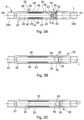
- An example of the close mechanism is described further below with reference to Figures 3A to 3C .
- the inlet When the inlet is open, fluid communication through the aperture is obtained, and the internal pathway (arrows B) is obtained.
- a sleeve 42 When the inlet 22 is closed, a sleeve 42 is arranged to cover the aperture to prevent fluid communication therethrough.
- the flow sub 20 is run-in/immerged as seen in Figure 2 with the inlet open to provide the desired fluid communication through an internal pathway.
- the flow sub 20 also has a destructible barrier 60, e.g. rupture body such as a glass burst disc, in a main bore of the tubular body 23.
- the destructible barrier 60 is mounted to the tubular body 23 toward a downhole end.
- the destructible barrier 60 can be destroyed by applying pressure in the fluid contained inside the tubing string 5 such that the disc yields and breaks. Destroying the barrier 60 opens up the main bore 23 for allowing production to take place and reservoir hydrocarbon fluid to travel through the inside of the string 5, through the bore of the tubular body 23 and tubular body 11 and toward the surface.
- Figure 2 shows a vertical section of a wellbore where relative positions along the string can be described by terms “above” and “below", it will be appreciated that a wellbore can in general have sections which may be horizontal, vertical, or inclined, and even show a curvature.
- the inlet 22 provides fluid communication with the interior of the tubing string so that the fluid in the wellbore in front of the packer 10 can enter the interior of the tubing string 5 when the packer 10 is moving towards a bottom of the wellbore.
- the inlet 22 is capable of letting fluid into the tubing string 5 that would otherwise flow through the gap 8 in the annular space surrounding the packer 10 and thus increase the drag forces created thereupon.
- the string 5 is run in with the inlet 22 in open configuration as shown in Figure 2 until the desired location for installation is reached. Once in location, the inlet 22 is closed, for allowing the packer 10 then to be expanded.
- the flow sub 20 is in an open configuration where the inlet 22 is open and provides fluid communication through the aperture 24 in the wall of the tubular body 23, during run-in as described above in relation to Figure 2 .
- the flow sub 20 has first and second end portions 25a, 25b connected at either end to the tubular body 23.
- the first and second end portions 25a, 25c are adapted to allow connection to adjacent sections in the string 5.
- the sleeve 42 is housed on an inside of the tubular body 23, and can be activated to slide relative to the tubular body 23, along the longitudinal axis L toward a downhole end 31.
- the sleeve 42 has a seat 35 for receiving a ball dropped into the tubing string 5 from topsides for activating the sleeve 42.
- a spring 46 is arranged on an inside of the tubular body in an annular slot 47 formed between an inner wall 48 of the tubular body 23 and spring retainer 49.
- the spring 46 acts between abutment surfaces 26, 27 on the end portion 25a and the sleeve 42 respectively, so as to be arranged to exert an axial force on the sleeve 42 in the longitudinal direction.
- the spring 46 is in compression in Figure 3A so as to exert a push force against the sleeve 42 toward the downhole end 31.
- the spring 46 is provided so that the sleeve closes spontaneously.
- the sleeve 42 is held in fixed position relative to the body 23, against the force of the spring 46, by way of shear pins 61.
- the shear pins 61 are provided to fasten the sleeve 42 in the open position, as shown in Figure 3A .
- Each shear pin 61 protrudes radially inward from the wall of the tubular body 23 and has an end which is received in a formation in an outer surface of the sleeve 42, so that the pin 61 locks the sleeve 42 with respect to the tubular body 23.
- the shear pins 61 can therefore prevent the sleeve 42 from closing the inlet 22 during run in.
- this arrangement Since the spring 46 is in a compressed state, this arrangement stores potential energy in the spring 46 that may be released for the purpose of closing the sleeve when the shear pins are broken off.
- the sleeve 42 is activated by dropping a ball 55 from a top end of the tubing string 5 such that it passes downhole through an inside of the tubing string 5.
- the ball 55 may be driven by applied fluid pressure behind the ball 55 to urge it along the tubing string 5 toward the location of the seat 35. Fluid in the tubing string 5 ahead of the ball 55 may exit through the aperture 24 to prevent "hydraulic lock".
- the ball 55 passes down the internal bore 52 and lands on the seat 35 where it comes to rest and forms a fluid tight seal against the seat 35.
- the activation of the sleeve is initiated when the object lands on the seat in the tubing string.
- Figures 3B and 3C show the progressive movement of the sleeve 42 into the fully closed configuration as shown in Figure 3C , after the shear pins 61 are broken.
- the inlet 22 is totally obstructed by the sleeve 42, and no fluid communication is possible between the inside and the outside of the tubing string 5.
- the spring 46 increases in extension from Figure 3A to 3C .
- the ball 55 is made of material that is fluid-dissolvable.
- the ball 55 is used initially to close the inlet 22 as described above, but after a time it dissolves in the presence of the fluid inside the tubing string 5 such that it is removed. Removal of the ball is useful because the bore 57 can then be opened up for allowing hydrocarbon production or other operations to be performed.
- the spring 46 alone urges the sleeve 42 to remain in position and keeps the inlet 22 closed, e.g. while production takes place.
- other objects e.g. other drop objects such as darts or the like, may be delivered through the inside of the tubing string and utilised to activate the sleeve 42.
- Such objects may or may not be dissolvable.
- the sleeve may be closed in many ways, and using a spring and shear pins as described above is only way of doing it.
- electronic means may be provided to activate the sleeve in reaction to the landing of the object on the seat; the compressed spring may be replaced by any other solution that would push the sleeve to the closed position, such as a compressed fluid; instead of the spring, the space in the tubing string that is closed by the object on the seat may be used as a pressure chamber to push the sleeve to the closed position; or the shear pins may be replaced by a locking mechanism activated electronically.
- An advantage of the approach described with reference to Figures 3A to 3C using a spring and shear pins, is that it can be simple to implement.
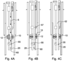
- Figure 4A firstly illustrates the inlet 22 in closed configuration as a result of closing the sleeve as explained in relation to Figures 3A-3C .
- the ball 55 is deployed in the tubing string 5, which in turn activates the sleeve 42 and closes the inlet 22.
- the tubing string 5 is now extended so that the packer 10 is at the position in the wellbore at which it will be expanded to form a seal against the surrounding surface of the wellbore wall.
- Figure 4B illustrates the production packer being expanded and tested.
- the pressure of fluid contained inside the tubing string in the region 57 is increased to hydraulically operate packer so that the sealing elements 12 expand and are brought into contact with the wall of the wellbore.
- the ball 55 remains on the seat 35 while the pressure in the region 57 is increased as required.
- the ball 55 may be removed before activating the packer 10, e.g. by letting it dissolve, and the region 57 may be pressured up to activate the packer directly against a rupture body 60
- test is carried out by filling the tubing string with a dense fluid, such as heavy mud, and checking if the seal of the packer 10 holds the tubing string 5 in place against the wellbore wall.
- Another test may be carried out by filling or pressurising the annulus 6 above the packer 10 and checking if there any leakage across the seal.
- the region 57 of the interior of the tubing string 5 (uphole of the ball 55 or rupture body 60 and up to the top end of the string), provides in effect a chamber for containing fluid that can be pressurised from topsides equipment, e.g. by pumping a fluid into the tubing at the top of the wellbore.
- the chamber can facilitate both expanding the packer 10 by increasing the pressure inside the tubing string 5, and carrying out at least one test for making sure that the seal of the packer 10 is well formed, for example in accordance with a standard for the certification of well barriers.
- the ball 55 is composed of dissolvable material, at some point in time the object will disintegrate. Such disintegration may take place before the expandable device is expanded, after the expansion, or after the tests. In the end, the tubing string needs to be made ready for production.
- the rupture body 60 needs to be removed using a suitable method, such as by pressurising the fluid in the region 57 beyond the pre-designed rupture limits.
- Figure 4C illustrates a final state, in which the ball 55 is not present because it has been dissolved, and the rupture body 60 is not present because it has been removed.
Landscapes
- Life Sciences & Earth Sciences (AREA)
- Engineering & Computer Science (AREA)
- Geology (AREA)
- Mining & Mineral Resources (AREA)
- Physics & Mathematics (AREA)
- Environmental & Geological Engineering (AREA)
- Fluid Mechanics (AREA)
- General Life Sciences & Earth Sciences (AREA)
- Geochemistry & Mineralogy (AREA)
- Pipe Accessories (AREA)
Claims (10)
- Un système (1) comprenant :- un dispositif (20) adapté pour être exécuté sur une colonne de tubage (5) dans un puits de forage (2) ; et- un corps de réglage (55),dans lequel le dispositif (20) comprend :- un corps tubulaire (11, 23) adapté pour former une portion de la colonne de tubage ,- au moins une entrée (22) pour permettre l'entrée d'un fluide dans la colonne de tubage (5), dans lequel la au moins une entrée est au moins une ouverture (24) dans une paroi du corps tubulaire (11, 23) ;- un mécanisme de fermeture (40) pour fermer la au moins une entrée (22), dans lequel le mécanisme de fermeture (40) comprend un membre mobile (42) qui peut être mu d'une première position, où un fluide peut être reçu à partir de l'extérieur de la colonne de tubage (5) vers l'intérieur de la colonne de tubage (5) à travers la au moins une entrée (22), vers une seconde position pour fermer la au moins une entrée (22) ; et- un élément attrapeur (35) accouplé au membre mobile (42),dans lequel, dans une configuration pour l'immersion de la colonne de tubage (5) dans un fluide à l'intérieur du puits de forage (2), le membre mobile (42) est en première position et la au moins une entrée (22) est ouverte pour laisser le fluide entrer dans la colonne de tubage (5),dans lequel le mécanisme de fermeture (40) peut être exécuté pour fermer à travers le corps de réglage (55),dans lequel le membre mobile (42) peut être mu de la première position vers la seconde position par une force exercée par le corps de réglage (55), le corps de réglage (55) étant reçu dans l'élément attrapeur (35),dans lequel l'élément attrapeur (35) reçoit le corps de réglage (55) dans un alésage interne du dispositif (20) etdans lequel le corps de réglage est un objet (55) inséré dans une extrémité supérieure de la colonne de tubage (5),dans lequel l'objet (55) peut être dissous dans un fluide, tel que, lorsque le dispositif a été exécuté sur une colonne de tubage dans un puits de forage dans la configuration pour l'immersion de la colonne de tubage (5), et lorsque l'objet a été reçu dans l'élément attrapeur et le membre mobile (42) a été mu de la première position vers la seconde position, l'objet se dissolve après un certain temps en présence du fluide qui est entré dans la colonne de tubage (5) à travers la au moins une entrée (22),caractérisé en ce que le dispositif comprend une barrière destructible positionnée au fond du puits par rapport à la au moins une entrée,dans lequel la barrière destructible isole l'intérieur de la colonne de tubage pour permettre au fluide dans l'intérieur isolé de la colonne de tubage d'être mis sous pression lorsque la au moins une entrée est fermée.
- Un système selon la revendication 1, dans lequel la barrière destructible est arrangée pour être détruite en faisant pression dans l'intérieur isolé de la colonne de tubage, tel qu'un alésage s'ouvre à l'intérieur de la colonne de tubage.
- Un système selon l'une quelconque des revendications 1 à 2, dans lequel le membre mobile est un manchon coulissant.
- Un système selon l'une quelconque des revendications 1 à 3, dans lequel l'objet est une boule, et l'élément attrapeur est un siège pour recevoir la boule.
- Un système selon l'une quelconque des revendications 1 à 4, dans lequel le dispositif comprend au moins un dispositif de retenue pour maintenir le membre mobile en position ouverte dans la configuration d'immersion.
- Un système selon la revendication 5, dans lequel le mécanisme de fermeture comprend au moins un moyen de polarisation pour fermer le membre mobile spontanément lorsque le au moins un dispositif de retenue est cisaillé de manière à libérer le membre mobile.
- Une colonne de tubage comprenant un système tel que décrit dans l'une quelconque des revendications précédentes.
- Une colonne de tubage selon la revendication 7, comprenant au moins un dispositif expansible, dans lequel le dispositif du système est monté au fond du puits par rapport au au moins un dispositif expansible.
- Un procédé d'exécution d'une colonne de tubage (5) à une profondeur souhaitée dans un puits de forage (2) ayant du fluide de puits de forage à l'intérieur, caractérisé en ce que la colonne de tubage (5) est conforme à l'une quelconque des revendications 7 ou 8, et dans lequel le procédé comprend les étapes suivantes :- fournir le dispositif (20) sur la colonne de tubage (5), le dispositif (20) étant dans la configuration d'immersion ;- étendre la colonne de tubage (5) jusqu'à ce qu'elle atteigne la profondeur souhaitée ; et- déployer l'objet (55) dans l'intérieur de la colonne de tubage (5), en insérant l'objet (55) dans l'extrémité supérieure de la colonne de tubage (5), tel que le mécanisme de fermeture (40) du dispositif (20) soit exécuté pour fermer la au moins une entrée (22) du dispositif (20).
- Un procédé selon la revendication 9, le procédé comprenant mettre le fluide à l'intérieur de la colonne sous pression pour exécuter les étapes suivantes :lorsque la colonne de tubage (5) est conforme à la revendication 8 :- étendre un dispositif expansible fourni sur la colonne de tubage de manière à former un joint contre une surface environnante ; et- exécuter au moins un test pour tester le joint formé par le dispositif expansible, et/oulorsque la colonne de tubage (5) de la revendication 7 ou 8 comprend un système tel que décrit dans la revendication 2 :- détruire le membre de la barrière destructible tel que l'alésage s'ouvre à l'intérieur de la colonne.
Priority Applications (2)
| Application Number | Priority Date | Filing Date | Title |
|---|---|---|---|
| EP18157788.3A EP3530873B1 (fr) | 2018-02-21 | 2018-02-21 | Dispositif adapté pour être exécuté sur une colonne de tubage dans un puits de forage |
| PCT/NO2019/050039 WO2019164406A1 (fr) | 2018-02-21 | 2019-02-20 | Dispositif conçu pour être posé sur une colonne de production dans un puits de forage |
Applications Claiming Priority (1)
| Application Number | Priority Date | Filing Date | Title |
|---|---|---|---|
| EP18157788.3A EP3530873B1 (fr) | 2018-02-21 | 2018-02-21 | Dispositif adapté pour être exécuté sur une colonne de tubage dans un puits de forage |
Publications (2)
| Publication Number | Publication Date |
|---|---|
| EP3530873A1 EP3530873A1 (fr) | 2019-08-28 |
| EP3530873B1 true EP3530873B1 (fr) | 2023-10-11 |
Family
ID=61256641
Family Applications (1)
| Application Number | Title | Priority Date | Filing Date |
|---|---|---|---|
| EP18157788.3A Active EP3530873B1 (fr) | 2018-02-21 | 2018-02-21 | Dispositif adapté pour être exécuté sur une colonne de tubage dans un puits de forage |
Country Status (2)
| Country | Link |
|---|---|
| EP (1) | EP3530873B1 (fr) |
| WO (1) | WO2019164406A1 (fr) |
Citations (1)
| Publication number | Priority date | Publication date | Assignee | Title |
|---|---|---|---|---|
| WO2015073001A1 (fr) * | 2013-11-14 | 2015-05-21 | Schlumberger Canada Limited | Système et méthodologie pour une utilisation d'un objet dégradable dans un tubage |
Family Cites Families (7)
| Publication number | Priority date | Publication date | Assignee | Title |
|---|---|---|---|---|
| US2695066A (en) * | 1949-10-18 | 1954-11-23 | Baker Oil Tools Inc | Hydraulically actuated well tool |
| US4529038A (en) * | 1982-08-19 | 1985-07-16 | Geo Vann, Inc. | Differential vent and bar actuated circulating valve and method |
| US5181569A (en) * | 1992-03-23 | 1993-01-26 | Otis Engineering Corporation | Pressure operated valve |
| US5810084A (en) * | 1996-02-22 | 1998-09-22 | Halliburton Energy Services, Inc. | Gravel pack apparatus |
| US5775428A (en) * | 1996-11-20 | 1998-07-07 | Baker Hughes Incorporated | Whipstock-setting apparatus |
| US6769490B2 (en) * | 2002-07-01 | 2004-08-03 | Allamon Interests | Downhole surge reduction method and apparatus |
| US20100032167A1 (en) * | 2008-08-08 | 2010-02-11 | Adam Mark K | Method for Making Wellbore that Maintains a Minimum Drift |
-
2018
- 2018-02-21 EP EP18157788.3A patent/EP3530873B1/fr active Active
-
2019
- 2019-02-20 WO PCT/NO2019/050039 patent/WO2019164406A1/fr not_active Ceased
Patent Citations (1)
| Publication number | Priority date | Publication date | Assignee | Title |
|---|---|---|---|---|
| WO2015073001A1 (fr) * | 2013-11-14 | 2015-05-21 | Schlumberger Canada Limited | Système et méthodologie pour une utilisation d'un objet dégradable dans un tubage |
Also Published As
| Publication number | Publication date |
|---|---|
| WO2019164406A1 (fr) | 2019-08-29 |
| EP3530873A1 (fr) | 2019-08-28 |
Similar Documents
| Publication | Publication Date | Title |
|---|---|---|
| US9683424B2 (en) | Apparatus for injecting a fluid into a geological formation | |
| US11060376B2 (en) | System for stimulating a well | |
| US11047202B2 (en) | Top plug with transitionable seal | |
| CA2980066C (fr) | Appareil et methode de descente d'un tubage de puits dans un trou de forage | |
| CA2599802C (fr) | Vanne d'isolement de fond de trou et methode d'utilisation | |
| CA3039476C (fr) | Systeme de suspension de tubage avec bouchons de verrouillage | |
| US10107072B2 (en) | Toe valve | |
| US8104538B2 (en) | Fracturing with telescoping members and sealing the annular space | |
| US8327937B2 (en) | Equipment for remote launching of cementing plugs | |
| US20140318780A1 (en) | Degradable component system and methodology | |
| US10267118B2 (en) | Apparatus for injecting a fluid into a geological formation | |
| US11639641B2 (en) | Degradable in-line buoyant system for running casing in a wellbore | |
| US8826985B2 (en) | Open hole frac system | |
| RU2726710C2 (ru) | Система заканчивания скважины, обеспечивающая герметичность относительно покрывающего слоя | |
| US8316931B2 (en) | Equipment for remote launching of cementing plugs | |
| US20220136367A1 (en) | Downhole inflow production restriction device | |
| EP3353373B1 (fr) | Procédés de placement d'un matériau formant barrière dans un puits de forage afin de laisser le tubage de façon permanente dans le coffrage pour cessation permanente d'exploitation de puits de forage | |
| WO2017150981A1 (fr) | Appareil pour injecter un fluide dans une formation géologique | |
| EP3530873B1 (fr) | Dispositif adapté pour être exécuté sur une colonne de tubage dans un puits de forage | |
| EP3746629B1 (fr) | Système et procédé de complétion | |
| US10871054B2 (en) | Closeable sleeve assembly and method of use | |
| EP2317065A1 (fr) | Équipement pour le lancement à distance de bouchons de cimentation | |
| EP2761122A1 (fr) | Procédé et système de fracturation hydraulique |
Legal Events
| Date | Code | Title | Description |
|---|---|---|---|
| PUAI | Public reference made under article 153(3) epc to a published international application that has entered the european phase |
Free format text: ORIGINAL CODE: 0009012 |
|
| STAA | Information on the status of an ep patent application or granted ep patent |
Free format text: STATUS: THE APPLICATION HAS BEEN PUBLISHED |
|
| AK | Designated contracting states |
Kind code of ref document: A1 Designated state(s): AL AT BE BG CH CY CZ DE DK EE ES FI FR GB GR HR HU IE IS IT LI LT LU LV MC MK MT NL NO PL PT RO RS SE SI SK SM TR |
|
| AX | Request for extension of the european patent |
Extension state: BA ME |
|
| STAA | Information on the status of an ep patent application or granted ep patent |
Free format text: STATUS: REQUEST FOR EXAMINATION WAS MADE |
|
| 17P | Request for examination filed |
Effective date: 20200219 |
|
| RBV | Designated contracting states (corrected) |
Designated state(s): AL AT BE BG CH CY CZ DE DK EE ES FI FR GB GR HR HU IE IS IT LI LT LU LV MC MK MT NL NO PL PT RO RS SE SI SK SM TR |
|
| STAA | Information on the status of an ep patent application or granted ep patent |
Free format text: STATUS: EXAMINATION IS IN PROGRESS |
|
| 17Q | First examination report despatched |
Effective date: 20200422 |
|
| RAP1 | Party data changed (applicant data changed or rights of an application transferred) |
Owner name: NOV INTERNATIONAL HOLDINGS C.V. |
|
| RAP1 | Party data changed (applicant data changed or rights of an application transferred) |
Owner name: GRANT PRIDECO, INC. |
|
| GRAP | Despatch of communication of intention to grant a patent |
Free format text: ORIGINAL CODE: EPIDOSNIGR1 |
|
| STAA | Information on the status of an ep patent application or granted ep patent |
Free format text: STATUS: GRANT OF PATENT IS INTENDED |
|
| INTG | Intention to grant announced |
Effective date: 20230612 |
|
| P01 | Opt-out of the competence of the unified patent court (upc) registered |
Effective date: 20230530 |
|
| GRAS | Grant fee paid |
Free format text: ORIGINAL CODE: EPIDOSNIGR3 |
|
| GRAA | (expected) grant |
Free format text: ORIGINAL CODE: 0009210 |
|
| STAA | Information on the status of an ep patent application or granted ep patent |
Free format text: STATUS: THE PATENT HAS BEEN GRANTED |
|
| AK | Designated contracting states |
Kind code of ref document: B1 Designated state(s): AL AT BE BG CH CY CZ DE DK EE ES FI FR GB GR HR HU IE IS IT LI LT LU LV MC MK MT NL NO PL PT RO RS SE SI SK SM TR |
|
| REG | Reference to a national code |
Ref country code: GB Ref legal event code: FG4D |
|
| REG | Reference to a national code |
Ref country code: CH Ref legal event code: EP |
|
| REG | Reference to a national code |
Ref country code: DE Ref legal event code: R096 Ref document number: 602018059044 Country of ref document: DE |
|
| REG | Reference to a national code |
Ref country code: IE Ref legal event code: FG4D |
|
| REG | Reference to a national code |
Ref country code: NO Ref legal event code: T2 Effective date: 20231011 |
|
| REG | Reference to a national code |
Ref country code: LT Ref legal event code: MG9D |
|
| REG | Reference to a national code |
Ref country code: NL Ref legal event code: MP Effective date: 20231011 |
|
| REG | Reference to a national code |
Ref country code: AT Ref legal event code: MK05 Ref document number: 1620399 Country of ref document: AT Kind code of ref document: T Effective date: 20231011 |
|
| PG25 | Lapsed in a contracting state [announced via postgrant information from national office to epo] |
Ref country code: NL Free format text: LAPSE BECAUSE OF FAILURE TO SUBMIT A TRANSLATION OF THE DESCRIPTION OR TO PAY THE FEE WITHIN THE PRESCRIBED TIME-LIMIT Effective date: 20231011 |
|
| PG25 | Lapsed in a contracting state [announced via postgrant information from national office to epo] |
Ref country code: GR Free format text: LAPSE BECAUSE OF FAILURE TO SUBMIT A TRANSLATION OF THE DESCRIPTION OR TO PAY THE FEE WITHIN THE PRESCRIBED TIME-LIMIT Effective date: 20240112 |
|
| PG25 | Lapsed in a contracting state [announced via postgrant information from national office to epo] |
Ref country code: IS Free format text: LAPSE BECAUSE OF FAILURE TO SUBMIT A TRANSLATION OF THE DESCRIPTION OR TO PAY THE FEE WITHIN THE PRESCRIBED TIME-LIMIT Effective date: 20240211 |
|
| PG25 | Lapsed in a contracting state [announced via postgrant information from national office to epo] |
Ref country code: LT Free format text: LAPSE BECAUSE OF FAILURE TO SUBMIT A TRANSLATION OF THE DESCRIPTION OR TO PAY THE FEE WITHIN THE PRESCRIBED TIME-LIMIT Effective date: 20231011 |
|
| PG25 | Lapsed in a contracting state [announced via postgrant information from national office to epo] |
Ref country code: AT Free format text: LAPSE BECAUSE OF FAILURE TO SUBMIT A TRANSLATION OF THE DESCRIPTION OR TO PAY THE FEE WITHIN THE PRESCRIBED TIME-LIMIT Effective date: 20231011 |
|
| PG25 | Lapsed in a contracting state [announced via postgrant information from national office to epo] |
Ref country code: ES Free format text: LAPSE BECAUSE OF FAILURE TO SUBMIT A TRANSLATION OF THE DESCRIPTION OR TO PAY THE FEE WITHIN THE PRESCRIBED TIME-LIMIT Effective date: 20231011 |
|
| PG25 | Lapsed in a contracting state [announced via postgrant information from national office to epo] |
Ref country code: LT Free format text: LAPSE BECAUSE OF FAILURE TO SUBMIT A TRANSLATION OF THE DESCRIPTION OR TO PAY THE FEE WITHIN THE PRESCRIBED TIME-LIMIT Effective date: 20231011 Ref country code: IS Free format text: LAPSE BECAUSE OF FAILURE TO SUBMIT A TRANSLATION OF THE DESCRIPTION OR TO PAY THE FEE WITHIN THE PRESCRIBED TIME-LIMIT Effective date: 20240211 Ref country code: GR Free format text: LAPSE BECAUSE OF FAILURE TO SUBMIT A TRANSLATION OF THE DESCRIPTION OR TO PAY THE FEE WITHIN THE PRESCRIBED TIME-LIMIT Effective date: 20240112 Ref country code: ES Free format text: LAPSE BECAUSE OF FAILURE TO SUBMIT A TRANSLATION OF THE DESCRIPTION OR TO PAY THE FEE WITHIN THE PRESCRIBED TIME-LIMIT Effective date: 20231011 Ref country code: BG Free format text: LAPSE BECAUSE OF FAILURE TO SUBMIT A TRANSLATION OF THE DESCRIPTION OR TO PAY THE FEE WITHIN THE PRESCRIBED TIME-LIMIT Effective date: 20240111 Ref country code: AT Free format text: LAPSE BECAUSE OF FAILURE TO SUBMIT A TRANSLATION OF THE DESCRIPTION OR TO PAY THE FEE WITHIN THE PRESCRIBED TIME-LIMIT Effective date: 20231011 Ref country code: PT Free format text: LAPSE BECAUSE OF FAILURE TO SUBMIT A TRANSLATION OF THE DESCRIPTION OR TO PAY THE FEE WITHIN THE PRESCRIBED TIME-LIMIT Effective date: 20240212 |
|
| PG25 | Lapsed in a contracting state [announced via postgrant information from national office to epo] |
Ref country code: SE Free format text: LAPSE BECAUSE OF FAILURE TO SUBMIT A TRANSLATION OF THE DESCRIPTION OR TO PAY THE FEE WITHIN THE PRESCRIBED TIME-LIMIT Effective date: 20231011 Ref country code: RS Free format text: LAPSE BECAUSE OF FAILURE TO SUBMIT A TRANSLATION OF THE DESCRIPTION OR TO PAY THE FEE WITHIN THE PRESCRIBED TIME-LIMIT Effective date: 20231011 Ref country code: PL Free format text: LAPSE BECAUSE OF FAILURE TO SUBMIT A TRANSLATION OF THE DESCRIPTION OR TO PAY THE FEE WITHIN THE PRESCRIBED TIME-LIMIT Effective date: 20231011 Ref country code: LV Free format text: LAPSE BECAUSE OF FAILURE TO SUBMIT A TRANSLATION OF THE DESCRIPTION OR TO PAY THE FEE WITHIN THE PRESCRIBED TIME-LIMIT Effective date: 20231011 Ref country code: HR Free format text: LAPSE BECAUSE OF FAILURE TO SUBMIT A TRANSLATION OF THE DESCRIPTION OR TO PAY THE FEE WITHIN THE PRESCRIBED TIME-LIMIT Effective date: 20231011 |
|
| PG25 | Lapsed in a contracting state [announced via postgrant information from national office to epo] |
Ref country code: DK Free format text: LAPSE BECAUSE OF FAILURE TO SUBMIT A TRANSLATION OF THE DESCRIPTION OR TO PAY THE FEE WITHIN THE PRESCRIBED TIME-LIMIT Effective date: 20231011 |
|
| REG | Reference to a national code |
Ref country code: DE Ref legal event code: R097 Ref document number: 602018059044 Country of ref document: DE |
|
| PG25 | Lapsed in a contracting state [announced via postgrant information from national office to epo] |
Ref country code: CZ Free format text: LAPSE BECAUSE OF FAILURE TO SUBMIT A TRANSLATION OF THE DESCRIPTION OR TO PAY THE FEE WITHIN THE PRESCRIBED TIME-LIMIT Effective date: 20231011 |
|
| PG25 | Lapsed in a contracting state [announced via postgrant information from national office to epo] |
Ref country code: SK Free format text: LAPSE BECAUSE OF FAILURE TO SUBMIT A TRANSLATION OF THE DESCRIPTION OR TO PAY THE FEE WITHIN THE PRESCRIBED TIME-LIMIT Effective date: 20231011 |
|
| PG25 | Lapsed in a contracting state [announced via postgrant information from national office to epo] |
Ref country code: SM Free format text: LAPSE BECAUSE OF FAILURE TO SUBMIT A TRANSLATION OF THE DESCRIPTION OR TO PAY THE FEE WITHIN THE PRESCRIBED TIME-LIMIT Effective date: 20231011 Ref country code: SK Free format text: LAPSE BECAUSE OF FAILURE TO SUBMIT A TRANSLATION OF THE DESCRIPTION OR TO PAY THE FEE WITHIN THE PRESCRIBED TIME-LIMIT Effective date: 20231011 Ref country code: RO Free format text: LAPSE BECAUSE OF FAILURE TO SUBMIT A TRANSLATION OF THE DESCRIPTION OR TO PAY THE FEE WITHIN THE PRESCRIBED TIME-LIMIT Effective date: 20231011 Ref country code: IT Free format text: LAPSE BECAUSE OF FAILURE TO SUBMIT A TRANSLATION OF THE DESCRIPTION OR TO PAY THE FEE WITHIN THE PRESCRIBED TIME-LIMIT Effective date: 20231011 Ref country code: EE Free format text: LAPSE BECAUSE OF FAILURE TO SUBMIT A TRANSLATION OF THE DESCRIPTION OR TO PAY THE FEE WITHIN THE PRESCRIBED TIME-LIMIT Effective date: 20231011 Ref country code: DK Free format text: LAPSE BECAUSE OF FAILURE TO SUBMIT A TRANSLATION OF THE DESCRIPTION OR TO PAY THE FEE WITHIN THE PRESCRIBED TIME-LIMIT Effective date: 20231011 Ref country code: CZ Free format text: LAPSE BECAUSE OF FAILURE TO SUBMIT A TRANSLATION OF THE DESCRIPTION OR TO PAY THE FEE WITHIN THE PRESCRIBED TIME-LIMIT Effective date: 20231011 |
|
| PLBE | No opposition filed within time limit |
Free format text: ORIGINAL CODE: 0009261 |
|
| STAA | Information on the status of an ep patent application or granted ep patent |
Free format text: STATUS: NO OPPOSITION FILED WITHIN TIME LIMIT |
|
| REG | Reference to a national code |
Ref country code: DE Ref legal event code: R119 Ref document number: 602018059044 Country of ref document: DE |
|
| 26N | No opposition filed |
Effective date: 20240712 |
|
| PG25 | Lapsed in a contracting state [announced via postgrant information from national office to epo] |
Ref country code: MC Free format text: LAPSE BECAUSE OF FAILURE TO SUBMIT A TRANSLATION OF THE DESCRIPTION OR TO PAY THE FEE WITHIN THE PRESCRIBED TIME-LIMIT Effective date: 20231011 |
|
| REG | Reference to a national code |
Ref country code: CH Ref legal event code: PL |
|
| PG25 | Lapsed in a contracting state [announced via postgrant information from national office to epo] |
Ref country code: LU Free format text: LAPSE BECAUSE OF NON-PAYMENT OF DUE FEES Effective date: 20240221 |
|
| PG25 | Lapsed in a contracting state [announced via postgrant information from national office to epo] |
Ref country code: CH Free format text: LAPSE BECAUSE OF NON-PAYMENT OF DUE FEES Effective date: 20240229 |
|
| PG25 | Lapsed in a contracting state [announced via postgrant information from national office to epo] |
Ref country code: SI Free format text: LAPSE BECAUSE OF FAILURE TO SUBMIT A TRANSLATION OF THE DESCRIPTION OR TO PAY THE FEE WITHIN THE PRESCRIBED TIME-LIMIT Effective date: 20231011 |
|
| PG25 | Lapsed in a contracting state [announced via postgrant information from national office to epo] |
Ref country code: SI Free format text: LAPSE BECAUSE OF FAILURE TO SUBMIT A TRANSLATION OF THE DESCRIPTION OR TO PAY THE FEE WITHIN THE PRESCRIBED TIME-LIMIT Effective date: 20231011 Ref country code: LU Free format text: LAPSE BECAUSE OF NON-PAYMENT OF DUE FEES Effective date: 20240221 Ref country code: CH Free format text: LAPSE BECAUSE OF NON-PAYMENT OF DUE FEES Effective date: 20240229 |
|
| REG | Reference to a national code |
Ref country code: BE Ref legal event code: MM Effective date: 20240229 |
|
| PG25 | Lapsed in a contracting state [announced via postgrant information from national office to epo] |
Ref country code: DE Free format text: LAPSE BECAUSE OF NON-PAYMENT OF DUE FEES Effective date: 20240903 |
|
| PG25 | Lapsed in a contracting state [announced via postgrant information from national office to epo] |
Ref country code: BE Free format text: LAPSE BECAUSE OF NON-PAYMENT OF DUE FEES Effective date: 20240229 |
|
| PG25 | Lapsed in a contracting state [announced via postgrant information from national office to epo] |
Ref country code: FR Free format text: LAPSE BECAUSE OF NON-PAYMENT OF DUE FEES Effective date: 20240229 |
|
| PG25 | Lapsed in a contracting state [announced via postgrant information from national office to epo] |
Ref country code: IE Free format text: LAPSE BECAUSE OF NON-PAYMENT OF DUE FEES Effective date: 20240221 |
|
| PG25 | Lapsed in a contracting state [announced via postgrant information from national office to epo] |
Ref country code: IE Free format text: LAPSE BECAUSE OF NON-PAYMENT OF DUE FEES Effective date: 20240221 Ref country code: FR Free format text: LAPSE BECAUSE OF NON-PAYMENT OF DUE FEES Effective date: 20240229 Ref country code: DE Free format text: LAPSE BECAUSE OF NON-PAYMENT OF DUE FEES Effective date: 20240903 Ref country code: BE Free format text: LAPSE BECAUSE OF NON-PAYMENT OF DUE FEES Effective date: 20240229 |
|
| PG25 | Lapsed in a contracting state [announced via postgrant information from national office to epo] |
Ref country code: CY Free format text: LAPSE BECAUSE OF FAILURE TO SUBMIT A TRANSLATION OF THE DESCRIPTION OR TO PAY THE FEE WITHIN THE PRESCRIBED TIME-LIMIT; INVALID AB INITIO Effective date: 20180221 |
|
| PG25 | Lapsed in a contracting state [announced via postgrant information from national office to epo] |
Ref country code: HU Free format text: LAPSE BECAUSE OF FAILURE TO SUBMIT A TRANSLATION OF THE DESCRIPTION OR TO PAY THE FEE WITHIN THE PRESCRIBED TIME-LIMIT; INVALID AB INITIO Effective date: 20180221 |
|
| PG25 | Lapsed in a contracting state [announced via postgrant information from national office to epo] |
Ref country code: FI Free format text: LAPSE BECAUSE OF FAILURE TO SUBMIT A TRANSLATION OF THE DESCRIPTION OR TO PAY THE FEE WITHIN THE PRESCRIBED TIME-LIMIT Effective date: 20231011 |
|
| PG25 | Lapsed in a contracting state [announced via postgrant information from national office to epo] |
Ref country code: TR Free format text: LAPSE BECAUSE OF FAILURE TO SUBMIT A TRANSLATION OF THE DESCRIPTION OR TO PAY THE FEE WITHIN THE PRESCRIBED TIME-LIMIT Effective date: 20231011 |
|
| PGFP | Annual fee paid to national office [announced via postgrant information from national office to epo] |
Ref country code: GB Payment date: 20260106 Year of fee payment: 9 |
|
| PGFP | Annual fee paid to national office [announced via postgrant information from national office to epo] |
Ref country code: NO Payment date: 20260211 Year of fee payment: 9 |