EP3530886B1 - Mécanismes de transmission de bague de synchronisation d'aube variable - Google Patents
Mécanismes de transmission de bague de synchronisation d'aube variable Download PDFInfo
- Publication number
- EP3530886B1 EP3530886B1 EP19168258.2A EP19168258A EP3530886B1 EP 3530886 B1 EP3530886 B1 EP 3530886B1 EP 19168258 A EP19168258 A EP 19168258A EP 3530886 B1 EP3530886 B1 EP 3530886B1
- Authority
- EP
- European Patent Office
- Prior art keywords
- ring
- sun gear
- gear teeth
- gear
- recited
- Prior art date
- Legal status (The legal status is an assumption and is not a legal conclusion. Google has not performed a legal analysis and makes no representation as to the accuracy of the status listed.)
- Active
Links
Images


Classifications
-
- F—MECHANICAL ENGINEERING; LIGHTING; HEATING; WEAPONS; BLASTING
- F01—MACHINES OR ENGINES IN GENERAL; ENGINE PLANTS IN GENERAL; STEAM ENGINES
- F01D—NON-POSITIVE DISPLACEMENT MACHINES OR ENGINES, e.g. STEAM TURBINES
- F01D17/00—Regulating or controlling by varying flow
- F01D17/10—Final actuators
- F01D17/12—Final actuators arranged in stator parts
-
- F—MECHANICAL ENGINEERING; LIGHTING; HEATING; WEAPONS; BLASTING
- F01—MACHINES OR ENGINES IN GENERAL; ENGINE PLANTS IN GENERAL; STEAM ENGINES
- F01D—NON-POSITIVE DISPLACEMENT MACHINES OR ENGINES, e.g. STEAM TURBINES
- F01D17/00—Regulating or controlling by varying flow
- F01D17/10—Final actuators
- F01D17/12—Final actuators arranged in stator parts
- F01D17/14—Final actuators arranged in stator parts varying effective cross-sectional area of nozzles or guide conduits
- F01D17/16—Final actuators arranged in stator parts varying effective cross-sectional area of nozzles or guide conduits by means of nozzle vanes
- F01D17/162—Final actuators arranged in stator parts varying effective cross-sectional area of nozzles or guide conduits by means of nozzle vanes for axial flow, i.e. the vanes turning around axes which are essentially perpendicular to the rotor centre line
-
- F—MECHANICAL ENGINEERING; LIGHTING; HEATING; WEAPONS; BLASTING
- F01—MACHINES OR ENGINES IN GENERAL; ENGINE PLANTS IN GENERAL; STEAM ENGINES
- F01D—NON-POSITIVE DISPLACEMENT MACHINES OR ENGINES, e.g. STEAM TURBINES
- F01D9/00—Stators
- F01D9/02—Nozzles; Nozzle boxes; Stator blades; Guide conduits, e.g. individual nozzles
- F01D9/04—Nozzles; Nozzle boxes; Stator blades; Guide conduits, e.g. individual nozzles forming ring or sector
- F01D9/041—Nozzles; Nozzle boxes; Stator blades; Guide conduits, e.g. individual nozzles forming ring or sector using blades
-
- F—MECHANICAL ENGINEERING; LIGHTING; HEATING; WEAPONS; BLASTING
- F16—ENGINEERING ELEMENTS AND UNITS; GENERAL MEASURES FOR PRODUCING AND MAINTAINING EFFECTIVE FUNCTIONING OF MACHINES OR INSTALLATIONS; THERMAL INSULATION IN GENERAL
- F16H—GEARING
- F16H1/00—Toothed gearings for conveying rotary motion
- F16H1/28—Toothed gearings for conveying rotary motion with gears having orbital motion
- F16H1/36—Toothed gearings for conveying rotary motion with gears having orbital motion with two central gears coupled by intermeshing orbital gears
-
- F—MECHANICAL ENGINEERING; LIGHTING; HEATING; WEAPONS; BLASTING
- F16—ENGINEERING ELEMENTS AND UNITS; GENERAL MEASURES FOR PRODUCING AND MAINTAINING EFFECTIVE FUNCTIONING OF MACHINES OR INSTALLATIONS; THERMAL INSULATION IN GENERAL
- F16H—GEARING
- F16H19/00—Gearings comprising essentially only toothed gears or friction members and not capable of conveying indefinitely-continuing rotary motion
- F16H19/001—Gearings comprising essentially only toothed gears or friction members and not capable of conveying indefinitely-continuing rotary motion for conveying reciprocating or limited rotary motion
-
- F—MECHANICAL ENGINEERING; LIGHTING; HEATING; WEAPONS; BLASTING
- F05—INDEXING SCHEMES RELATING TO ENGINES OR PUMPS IN VARIOUS SUBCLASSES OF CLASSES F01-F04
- F05D—INDEXING SCHEME FOR ASPECTS RELATING TO NON-POSITIVE-DISPLACEMENT MACHINES OR ENGINES, GAS-TURBINES OR JET-PROPULSION PLANTS
- F05D2220/00—Application
- F05D2220/30—Application in turbines
- F05D2220/32—Application in turbines in gas turbines
-
- F—MECHANICAL ENGINEERING; LIGHTING; HEATING; WEAPONS; BLASTING
- F16—ENGINEERING ELEMENTS AND UNITS; GENERAL MEASURES FOR PRODUCING AND MAINTAINING EFFECTIVE FUNCTIONING OF MACHINES OR INSTALLATIONS; THERMAL INSULATION IN GENERAL
- F16H—GEARING
- F16H1/00—Toothed gearings for conveying rotary motion
- F16H1/28—Toothed gearings for conveying rotary motion with gears having orbital motion
- F16H1/2809—Toothed gearings for conveying rotary motion with gears having orbital motion with means for equalising the distribution of load on the planet gears
- F16H1/2836—Toothed gearings for conveying rotary motion with gears having orbital motion with means for equalising the distribution of load on the planet gears by allowing limited movement of the planet gears relative to the planet carrier or by using free floating planet gears
-
- Y—GENERAL TAGGING OF NEW TECHNOLOGICAL DEVELOPMENTS; GENERAL TAGGING OF CROSS-SECTIONAL TECHNOLOGIES SPANNING OVER SEVERAL SECTIONS OF THE IPC; TECHNICAL SUBJECTS COVERED BY FORMER USPC CROSS-REFERENCE ART COLLECTIONS [XRACs] AND DIGESTS
- Y02—TECHNOLOGIES OR APPLICATIONS FOR MITIGATION OR ADAPTATION AGAINST CLIMATE CHANGE
- Y02T—CLIMATE CHANGE MITIGATION TECHNOLOGIES RELATED TO TRANSPORTATION
- Y02T50/00—Aeronautics or air transport
- Y02T50/60—Efficient propulsion technologies, e.g. for aircraft
-
- Y—GENERAL TAGGING OF NEW TECHNOLOGICAL DEVELOPMENTS; GENERAL TAGGING OF CROSS-SECTIONAL TECHNOLOGIES SPANNING OVER SEVERAL SECTIONS OF THE IPC; TECHNICAL SUBJECTS COVERED BY FORMER USPC CROSS-REFERENCE ART COLLECTIONS [XRACs] AND DIGESTS
- Y10—TECHNICAL SUBJECTS COVERED BY FORMER USPC
- Y10T—TECHNICAL SUBJECTS COVERED BY FORMER US CLASSIFICATION
- Y10T74/00—Machine element or mechanism
- Y10T74/18—Mechanical movements
- Y10T74/18856—Oscillating to oscillating
- Y10T74/1888—Geared connections
Definitions
- the present disclosure relates to transmission mechanisms, and more particularly to transmission mechanisms, such as in synchronization rings for variable vanes in gas turbine engines.
- turbo fan engines for aircraft can include multiple stages of variable vanes to condition and guide airflow through the compressor and/or turbine sections.
- Variable vanes are configured to be pivoted about their respective vane axis to alter the angle of attack in order to optimize airflow characteristics for various operating conditions.
- Variable vanes can be connected to a synchronization ring (sync ring), each by a respective vane arm connected to the stem of the respective vane.
- the sync ring can drive each variable vane counter-clockwise and/or clockwise around its respective longitudinal axis in order to adjust vane stage angle for a particular operating condition.
- Bell-crank style mechanisms are commonly used to convert the linear or rotational force and displacement of an actuator output shaft into an equivalent force and displacement suitable for driving the sync ring over the desired range of angular rotation.
- the limitation on input angle for bell-crank style mechanisms can limit the mechanical advantage that can be achieved through the bell-crank mechanism. This can ultimately limit the accuracy of angle of attack for traditional variable vane systems.
- WO 2013/177785 A1 discloses a planetary gear transmission for an electric vehicle.
- EP 2626521 A1 discloses an actuation mechanism for variable vanes in a gas turbine engine using a unison ring assembly, where the term “unison ring” may be considered to be interchangeable with the term “synchronisation ring”.
- the present invention provides a transmission mechanism comprising: a planet gear configured to be mounted to a synchronization ring for rotation relative to the synchronization ring about a planet gear axis; a set of sun gear teeth meshed with teeth of the planet gear, wherein the set of sun gear teeth is configured to rotate and drive motion of the planet gear in a circumferential direction about an axis of the set of sun gear teeth; a set of ring gear teeth meshed with the teeth of the planet gear, wherein the set of sun gear teeth and the set of ring gear teeth are spaced apart from one another; and an input shaft configured to extend in a radially outward direction with respect to the synchronization ring, the input shaft having a first end and a second end, defining an actuator axis therebetween, wherein the set of sun gear teeth is defined proximate to the first end of the input shaft operatively connecting the input shaft to the planet gear; wherein the set of sun gear teeth is concentric with the input shaft.
- a center of the planet gear can be configured to move along an arcuate path.
- a circle defined by the arcuate path can be concentric with the set of sun gear teeth.
- the transmission mechanism can include an input shaft configured to extend in a radially outward direction with respect to a sync ring.
- the input shaft can have a first end and a second end and can define an actuator axis therebetween.
- the set of sun gear teeth can be defined proximate to the first end of the input shaft and can operatively connect the input shaft to the planet gear.
- the input shaft can be configured to rotate the set of sun gear teeth about the actuator axis.
- the set of sun gear teeth can be concentric with the input shaft.
- the input shaft can be configured to be normal to a rotation axis of a sync ring and to be mounted to the sun gear.
- the transmission mechanism can include a housing that can be operatively connected to the set of ring gear teeth.
- the housing can surround at least a portion of the set of sun gear teeth and/or the planet gear.
- the housing can be configured to be disposed radially outward of a sync ring mounted to the planet gear and can be configured to be stationary with respect to the set of ring gear teeth and an axis of the set of sun gear teeth.
- the planet gear can be configured to connect to a sync ring through a spherical joint.
- An end surface of the housing can define a gear plane.
- the spherical joint can be configured to allow the planet gear to remain parallel with respect to the gear plane throughout an arc of motion.
- the spherical joint can be configured to allow a sync ring to rotate about and move axially with respect to a centerline axis to follow the arc of motion of the planet gear.
- the set of ring gear teeth can be disposed on a partial ring gear defining a segment of a full ring gear.
- the set of sun gear teeth can be circumferentially disposed on a periphery of a partial sun gear defining a segment of a full sun gear.
- the present invention provides a variable vane system including a sync ring defining a centerline axis, a plurality of variable vanes, and the transmission mechanism of the first aspect.
- the transmission mechanism is configured to drive motion of sync ring in an axial and rotational direction with respect to the centerline axis.
- the plurality of variable vanes are operatively connected to the sync ring such that the axial and rotational motion of the sync ring drives the rotation of the variable vanes to adjust the angle of attack of the variable vanes.
- the variable vane system can include a plurality of vane arms operatively connecting an end of each variable vane to the sync ring.
- the housing can surround at least a portion of the transmission mechanism.
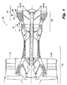
- FIG. 1 a cross-sectional view of an exemplary embodiment of the gas turbine engine constructed in accordance with the disclosure is shown in Fig. 1 and is designated generally by reference character 100.
- variable vane system 102 includes a case 104 and a plurality of variable vanes 106.
- Variable vane system 102 is disposed in a turbine section 103 of gas turbine engine 100.
- Variable vanes 106 are stator vanes and project radially inward from case 104.
- Variable vane system 102 is shown in a high pressure turbine section 105 but could also be applied in a low pressure turbine section 107.
- variable vane system 102 can also be disposed in a compressor section 101 of gas turbine engine 100, or can be used in any other suitable application.
- variable vane system 102 includes a synchronization ring 108 (sync ring) disposed radially inward of case 104 defining a centerline axis A and a transmission mechanism 110. While sync ring 108 is shown and described herein as being disposed radially inward of case 104, those skilled in the art will readily appreciate that, depending on the application, sync ring 108 can be disposed radially outward of case 104. Variable vanes 106 project radially inward from case 104.
- the sync ring 108 is operatively connected to the variable vanes 106 such that the axial and rotational motion of sync ring 108 drives the rotation of variable vanes 106 about a vane axis B to adjust their angle of attack.
- the rotation of sync ring 108 about centerline axis A is indicated schematically by a double-headed arrow.
- the rotation of variable vanes 106 about vane axis B is also indicated schematically by a separate double-headed arrow.
- Variable vane system 102 includes a plurality of vane arms 114 operatively connecting a vane stem of each variable vane 106 to sync ring 108.
- transmission mechanism 110 includes a planet gear 116, a set of sun gear teeth 118 and a set of ring gear teeth 120.
- Planet gear 116 is mounted to sync ring 108 for rotation relative to sync ring 108 about a planet gear axis C.
- Transmission mechanism 110 includes a ring gear segment 122.
- the set of ring gear teeth 120 is disposed on a partial ring gear 121 defining ring gear segment 122.
- Transmission mechanism 110 converts the rotational motion of an input shaft 124, described below, into curvilinear motion for driving sync ring 108.
- transmission mechanism 110 includes a full sun gear 117.
- the set of sun gear teeth 118 is circumferentially disposed on a periphery of a partial sun gear 119 defining a segment of full sun gear 117.
- the sun gear teeth 118 mesh with teeth 112 of planet gear 116.
- the sun gear teeth 118 are configured to rotate and drive the motion of planet gear 116 in a circumferential direction, about an axis D of the set of sun gear teeth 118.
- the ring gear teeth 120 are meshed with teeth 112 of planet gear 116.
- the sun gear teeth 118 and the ring gear teeth 120 are spaced apart from one another, so as not to interfere with one another.
- the sun gear teeth 118 are configured to rotate and drive motion of sync ring 108 in an axial and rotational direction with respect to the centerline axis A, indicated by the double-headed arrow in Fig. 2 .
- a center 115 of planet gear 116 is configured to move along an arcuate path indicated schematically by the arrows in Fig. 3 .
- a circle defined by the arcuate path is concentric with sun gear 117 and the set of sun gear teeth 118.
- sync ring 108 due to the connection of sync ring 108 and vane arms 114, a single point on the surface of sync ring 108 moves in a curvilinear path as sync ring 108 is moved through its incremental range of positive and negative angular rotation about centerline axis A.
- this displacement path is viewed from any plane whose normal intersects centerline axis A, the path of sync ring 108 displacement appears as a simple arc, similar to the arcuate path traveled by center 115 of planet gear 116.
- the radius of this simple arc of travel of planet gear 116 is equal to one half of the sum of the pitch diameters of sun gear 117 and planet gear 116.
- transmission mechanism 110 includes an input shaft 124 extending in a radially outward direction with respect to case 104.
- Input shaft 124 has a first end 125 and a second end 127 and defines an actuator axis therebetween.
- the actuator axis is the same as axis D of the set of sun gear teeth 118 because sun gear 117 is concentric with input shaft 124.
- Sun gear 117 is positioned proximate to first end 125 of input shaft 124 and operatively connects input shaft 124 to planet gear 116.
- Input shaft 124 is configured to rotate sun gear 117 about actuator axis D.
- Input shaft 124 is mounted normal relative to the centerline axis A of sync ring 108.
- transmission mechanism 110 includes a housing 126 that is connected to ring gear segment 122.
- Housing 126 surrounds at least a portion of sun gear 117 and/or a portion of planet gear 116.
- housing 126 is mounted radially outward of sync ring 108 and case 104 and is configured to be stationary with respect to ring gear segment 122 and an axis of sun gear 117 and to case 104.
- Axis D of sun gear 117 is coincident with actuator axis D.
- the diameter of sun gear 117 (and consequently, the diameter of planet gear 116) can be varied such the gear ratio of sun gear 117 to planet gear 116 can be set to any suitable value for a given application.
- the distance between the center of sun gear 117 and center 115 of planet gear 116 for any given application depends on the radius at which planet gear 116 is attached to sync ring 108.
- the diametral pitch of the gear set can be chosen such that there are an integral number of teeth on planet gear 116.
- sun gear 117 will make less than a full turn when the system is operated over the total required range of operation, then a full sun gear, e.g. sun gear 117, is not required and only sun gear teeth 118, e.g. a portion of full sun gear 117, is required to have an integral number of teeth, as will be described below.
- planet gear 116 is connected to sync ring 108 through a spherical joint 128.
- An end surface 129 of housing 126 defines a gear plane E, which extends in and out of the page, as shown in Fig. 4 .
- gear plane E which extends in and out of the page, as shown in Fig. 4 .
- radial line F shown in Fig. 4
- Radial line F is normal to gear plane E while radial line G is not normal to gear plane E due to the rotation of sync ring 108 about centerline axis A.
- spherical joint 128 is configured to allow planet gear 116 remain substantially parallel to gear plane E while allowing sync ring 108 to rotate about and move axially with respect to centerline axis A.
- spherical joint 128 to absorb the misalignment brought about by rotating sync ring 108 about centerline axis A, there can be a displacement of planet gear 116 relative to the gear plane E, i.e. planet gear 116 will move vertically with respect to gear plane E, as oriented in Fig. 4 .
- the thickness of planet gear 116, sun gear 117, and ring gear segment 122 can be configured to allow for this vertical motion.
- a transmission mechanism 210 is similar to transmission mechanism 110, described above.
- a partial sun gear 219 makes less than a full turn when the system is operated over the total required range of operation, therefore a full sun gear, e.g. sun gear 117, is not required.
- a set of sun gear teeth 218 are circumferentially disposed on a periphery of partial sun gear 219, while a portion 230 of partial sun gear 219 remains without sun gear teeth 218.
- transmission mechanisms e.g. transmission mechanisms 110 and 210
- transmission mechanisms 110 and 210 tend to provide an increased mechanical advantage compared to that of a traditional bell-crank mechanism.
- the limitation on input angle means that a maximum mechanical advantage of 3:1 can be achieved.
- This 90 degree limitation on the input angle of a bell-crank mechanism is generally imposed to maintain an approximately linear correlation between the input angle and the output displacement of the bell-crank mechanism. Any other suitable mechanical advantage can be used for a given application without departing from the scope of this disclosure.
- variable vane position is generally measured implicitly by measuring the angular position of an actuator output shaft.
- transmission mechanisms e.g. transmission mechanisms 110 and 210
- the vane position measurement tends to be more accurate than transmission systems having lower mechanical advantage and correspondingly smaller actuator output shaft displacement ranges.
- a bell-crank mechanism in order for a bell-crank mechanism to achieve a similar displacement to that of transmission mechanisms, e.g. transmission mechanisms 110 and 210, a bell-crank mechanism tends to require input from a larger actuator, capable of generating larger actuation forces, than is required for transmission mechanisms.
- larger actuation forces such as those used in traditional bell-crank mechanisms tend to require larger linkage components between the actuator and the bell-crank mechanism than those required for transmission mechanisms, tending to make the actuator system using the bell-crank mechanism heavier than one using transmission mechanisms.
Landscapes
- Engineering & Computer Science (AREA)
- General Engineering & Computer Science (AREA)
- Mechanical Engineering (AREA)
- Retarders (AREA)
Claims (15)
- Mécanisme de transmission (110 ; 210) comprenant :un train planétaire (116 ; 216) étant configuré pour être monté sur une bague de synchronisation (108) pour tourner par rapport à la bague de synchronisation autour d'un axe (C) de train planétaire ;un ensemble de dents de roue solaire (118 ; 218) en prise avec des dents (112) du train planétaire, dans lequel l'ensemble de dents de roue solaire est configuré pour tourner et entraîner le mouvement du train planétaire dans une direction circonférentielle autour d'un axe (D) de l'ensemble de dents de roue solaire ;un ensemble de dents de couronne dentée (120) en prise avec les dents du train planétaire, dans lequel l'ensemble de dents de roue solaire et l'ensemble de dents de couronne dentée sont espacés l'un de l'autre ; etun arbre d'entrée (124) étant configuré pour s'étendre dans une direction radialement vers l'extérieur par rapport à la bague de synchronisation, l'arbre d'entrée ayant une première extrémité (125) et une seconde extrémité (127), définissant entre elles un axe d'actionneur (D), dans lequel l'ensemble de dents de roue solaire est défini à proximité de la première extrémité de l'arbre d'entrée reliant fonctionnellement l'arbre d'entrée au train planétaire ;dans lequel l'ensemble de dents de roue solaire est concentrique avec l'arbre d'entrée.
- Mécanisme de transmission selon la revendication 1, dans lequel un centre (115) du train planétaire est configuré pour se déplacer le long d'un chemin arqué, dans lequel un cercle défini par le chemin arqué est concentrique avec l'ensemble de dents de roue solaire.
- Mécanisme de transmission selon la revendication 1 ou 2, dans lequel l'arbre d'entrée est configuré pour faire tourner l'ensemble de dents de roue solaire autour de l'axe d'actionneur.
- Mécanisme de transmission selon l'une quelconque des revendications 1, 2 ou 3, dans lequel l'arbre d'entrée est configuré pour être monté sur la roue solaire et pour être perpendiculaire à un axe central (A) de la bague de synchronisation.
- Mécanisme de transmission selon une quelconque revendication précédente, comprenant en outre un boîtier (126) relié fonctionnellement à l'ensemble de dents de couronne dentée et entourant au moins une partie d'au moins l'un de l'ensemble de dents de roue solaire et du train planétaire, dans lequel le boîtier est configuré pour être disposé radialement à l'extérieur de la bague de synchronisation et configuré pour être fixe par rapport à l'ensemble de dents de couronne dentée et à un axe (D) de l'ensemble de dents de roue solaire.
- Mécanisme de transmission selon une quelconque de revendication précédente, dans lequel le train planétaire est configuré pour être relié à la bague de synchronisation à travers un joint sphérique (128 ; 228), dans lequel une surface d'extrémité (129) d'un boitier (126) définit un plan de roue dentée (E), dans lequel le joint sphérique est configuré pour permettre au train planétaire de rester parallèle par rapport au plan de roue dentée tout au long d'un arc de mouvement, et dans lequel le joint sphérique est configuré pour permettre à la bague de synchronisation de tourner et de se déplacer axialement par rapport à un axe central (A) pour suivre un arc de mouvement du train planétaire.
- Mécanisme de transmission selon une quelconque de revendication précédente, dans lequel l'ensemble de dents de couronne dentée est disposé sur une couronne dentée partielle (121) définissant un segment (122 ; 222) d'une couronne dentée complète.
- Mécanisme de transmission selon une quelconque revendication précédente, dans lequel l'ensemble de dents de roue solaire est disposé circonférentiellement sur une périphérie d'une roue solaire partielle (119 ; 219) définissant un segment d'une roue solaire complète (117).
- Système à aube variable, comprenant :
le mécanisme de transmission selon la revendication 1, dans lequel :la bague de synchronisation définit un axe central (A) ;le train planétaire est monté radialement à l'extérieur de la bague de synchronisation ; etl'ensemble de dents de roue solaire actionne la bague de synchronisation pour un mouvement axial et rotatif par rapport à l'axe central ;une pluralité d'aubes variables (106) reliées fonctionnellement à la bague de synchronisation de sorte que le mouvement axial et rotatif de la bague de synchronisation entraîne la rotation des aubes variables pour ajuster l'angle d'attaque des aubes variables ; etledit arbre d'entrée (124) s'étend dans une direction radialement vers l'extérieur par rapport à la bague de synchronisation. - Système à aube variable selon la revendication 9, dans lequel un centre (115) du train planétaire est configuré pour se déplacer le long d'un chemin arqué, dans lequel un cercle défini par le chemin arqué est concentrique avec l'ensemble de dents de roue solaire.
- Système à aube variable selon les revendications 9 ou 10, comprenant en outre une pluralité de bras d'aube (114) reliant fonctionnellement une extrémité de chaque aube variable à la bague de synchronisation.
- Système à aube variable selon l'une quelconque des revendications 9 à 11, dans lequel l'arbre d'entrée est configuré pour faire tourner l'ensemble de dents de roue solaire autour de l'axe d'actionneur.
- Système à aube variable selon l'une quelconque des revendications 9 à 12, dans lequel l'arbre d'entrée est perpendiculaire à l'axe central de la bague de synchronisation.
- Système à aube variable selon l'une quelconque des revendications 9 à 13, comprenant en outre un boîtier (126) disposé radialement à l'extérieur de la bague de synchronisation, relié fonctionnellement à l'ensemble de dents de couronne dentée et entourant au moins une partie du mécanisme de transmission, dans lequel le boîtier est configuré pour être fixe par rapport à l'ensemble de dents de couronne dentée et à un axe (D) de l'ensemble de dents de roue solaire.
- Système à aube variable selon l'une quelconque des revendications 9 à 14, dans lequel le train planétaire est relié à la bague de synchronisation par l'intermédiaire d'un joint sphérique (128 ; 228), dans lequel une surface d'extrémité (129) d'un boîtier (126) définit un plan de roue dentée (E), dans lequel le joint sphérique est configuré pour permettre au train planétaire de rester parallèle par rapport au plan de roue dentée tout au long d'un arc de mouvement, et dans lequel le joint sphérique est configuré pour permettre à la bague de synchronisation de tourner et de se déplacer axialement par rapport à l'axe central pour suivre un arc de mouvement du train planétaire ; et/ou
dans lequel l'ensemble de dents de couronne dentée est disposé sur une couronne dentée partielle (121) définissant un segment (122 ; 222) d'une couronne dentée complète ; et/ou
dans lequel l'ensemble de dents de roue solaire est disposé circonférentiellement sur une périphérie d'une roue solaire partielle (119 ; 219) définissant un segment d'une roue solaire complète (117).
Applications Claiming Priority (3)
| Application Number | Priority Date | Filing Date | Title |
|---|---|---|---|
| US201461942770P | 2014-02-21 | 2014-02-21 | |
| EP17185912.7A EP3266988B1 (fr) | 2014-02-21 | 2015-02-23 | Mécanismes de transmission de bague de synchronisation d'aube variable |
| EP15156166.9A EP2910740B1 (fr) | 2014-02-21 | 2015-02-23 | Mécanismes de transmission d'anneau de synchronisation pour aubes variables |
Related Parent Applications (2)
| Application Number | Title | Priority Date | Filing Date |
|---|---|---|---|
| EP15156166.9A Division EP2910740B1 (fr) | 2014-02-21 | 2015-02-23 | Mécanismes de transmission d'anneau de synchronisation pour aubes variables |
| EP17185912.7A Division EP3266988B1 (fr) | 2014-02-21 | 2015-02-23 | Mécanismes de transmission de bague de synchronisation d'aube variable |
Publications (2)
| Publication Number | Publication Date |
|---|---|
| EP3530886A1 EP3530886A1 (fr) | 2019-08-28 |
| EP3530886B1 true EP3530886B1 (fr) | 2020-07-22 |
Family
ID=52577684
Family Applications (3)
| Application Number | Title | Priority Date | Filing Date |
|---|---|---|---|
| EP15156166.9A Active EP2910740B1 (fr) | 2014-02-21 | 2015-02-23 | Mécanismes de transmission d'anneau de synchronisation pour aubes variables |
| EP17185912.7A Active EP3266988B1 (fr) | 2014-02-21 | 2015-02-23 | Mécanismes de transmission de bague de synchronisation d'aube variable |
| EP19168258.2A Active EP3530886B1 (fr) | 2014-02-21 | 2015-02-23 | Mécanismes de transmission de bague de synchronisation d'aube variable |
Family Applications Before (2)
| Application Number | Title | Priority Date | Filing Date |
|---|---|---|---|
| EP15156166.9A Active EP2910740B1 (fr) | 2014-02-21 | 2015-02-23 | Mécanismes de transmission d'anneau de synchronisation pour aubes variables |
| EP17185912.7A Active EP3266988B1 (fr) | 2014-02-21 | 2015-02-23 | Mécanismes de transmission de bague de synchronisation d'aube variable |
Country Status (2)
| Country | Link |
|---|---|
| US (1) | US10012102B2 (fr) |
| EP (3) | EP2910740B1 (fr) |
Families Citing this family (8)
| Publication number | Priority date | Publication date | Assignee | Title |
|---|---|---|---|---|
| US10358934B2 (en) * | 2016-04-11 | 2019-07-23 | United Technologies Corporation | Method and apparatus for adjusting variable vanes |
| GB201613029D0 (en) * | 2016-07-28 | 2016-09-14 | Rolls Royce Plc | A sun gear drive arrangement |
| US10557371B2 (en) | 2017-07-14 | 2020-02-11 | United Technologies Corporation | Gas turbine engine variable vane end wall insert |
| CN108179969B (zh) * | 2017-12-18 | 2019-12-13 | 绍兴卓亚装饰材料有限公司 | 一种窗帘导轨 |
| US11480111B2 (en) * | 2019-05-15 | 2022-10-25 | Honeywell International Inc. | Variable area turbine nozzle and method |
| GB2589098A (en) * | 2019-11-19 | 2021-05-26 | Rolls Royce Plc | Variable vane mechanism |
| CN113202621B (zh) * | 2021-06-14 | 2022-04-01 | 中国航发沈阳发动机研究所 | 一种静子叶片转动角度调节机构 |
| US12006734B2 (en) * | 2021-06-18 | 2024-06-11 | Schlage Lock Company Llc | Rotation converter |
Family Cites Families (10)
| Publication number | Priority date | Publication date | Assignee | Title |
|---|---|---|---|---|
| US5205712A (en) * | 1991-05-13 | 1993-04-27 | Allied-Signal Inc. | Variable pitch fan gas turbine engine |
| JP3646966B2 (ja) | 1998-02-03 | 2005-05-11 | 富士重工業株式会社 | ハイブリッド車 |
| JP2001043940A (ja) | 1999-07-30 | 2001-02-16 | Fci Japan Kk | 電気コネクタ |
| CN2661479Y (zh) | 2003-04-24 | 2004-12-08 | 北京理工大学 | 电动汽车用单行星排两档变速箱 |
| CN2875938Y (zh) | 2005-11-25 | 2007-03-07 | 天津清源电动车辆有限责任公司 | 一种电动车辆用全自动二轴有级变速装置 |
| GB2465997A (en) | 2008-12-05 | 2010-06-09 | Gm Global Tech Operations Inc | A dual clutch transmission with Ravigneaux type planetary gearsets |
| CN101544181B (zh) | 2009-05-15 | 2011-04-20 | 新奥科技发展有限公司 | 动力总成系统 |
| CN102182801A (zh) | 2011-05-19 | 2011-09-14 | 苏州安远新能源动力有限公司 | 一种行星轮式电动汽车的两挡自动变速器 |
| GB201202383D0 (en) | 2012-02-13 | 2012-03-28 | Rolls Royce Plc | A unison ring gear assembly |
| CN104364148B (zh) | 2012-05-31 | 2017-05-03 | 罗伯特·博世有限公司 | 行星齿轮传动装置和电动车辆 |
-
2015
- 2015-02-16 US US14/623,296 patent/US10012102B2/en active Active
- 2015-02-23 EP EP15156166.9A patent/EP2910740B1/fr active Active
- 2015-02-23 EP EP17185912.7A patent/EP3266988B1/fr active Active
- 2015-02-23 EP EP19168258.2A patent/EP3530886B1/fr active Active
Non-Patent Citations (1)
| Title |
|---|
| None * |
Also Published As
| Publication number | Publication date |
|---|---|
| EP3266988B1 (fr) | 2019-04-10 |
| EP2910740B1 (fr) | 2017-08-23 |
| US10012102B2 (en) | 2018-07-03 |
| US20150354400A1 (en) | 2015-12-10 |
| EP2910740A1 (fr) | 2015-08-26 |
| EP3530886A1 (fr) | 2019-08-28 |
| EP3266988A1 (fr) | 2018-01-10 |
Similar Documents
| Publication | Publication Date | Title |
|---|---|---|
| EP3530886B1 (fr) | Mécanismes de transmission de bague de synchronisation d'aube variable | |
| US9797265B2 (en) | Stator vane adjusting device of a gas turbine | |
| US8435000B2 (en) | Variable vane actuation system | |
| US9617922B2 (en) | Jet engine actuation system | |
| US10577078B2 (en) | Systems and methods for electronic measurement of propeller blade angle | |
| US8905887B2 (en) | Unison ring gear assembly | |
| US20160032740A1 (en) | Variable-pitch rotor with remote counterweights | |
| US10837307B2 (en) | System of variable stator vanes for a turbine engine | |
| US10279889B2 (en) | Device for supplying hydraulic fluid to a ram and mechanism for controlling the pitch of the blades of a turbine engine propeller comprising the ram | |
| US10774672B2 (en) | Rotary actuator for variable vane adjustment system | |
| US20180017080A1 (en) | Variable stator vane mechanism | |
| US10766603B2 (en) | Pitch-change system equipped with means for adjusting blade pitch and corresponding turbine engine | |
| JP2017100701A (ja) | プロペラピッチ制御システム及び方法 | |
| JP6078103B2 (ja) | 遠隔のカウンタウェイトを有する可変ピッチロータ | |
| US10648359B2 (en) | System for controlling variable-setting blades for a turbine engine | |
| US10590957B2 (en) | Turbine engine compressor, in particular for an aircraft turboprop engine or turbojet engine | |
| JP6621807B2 (ja) | ブレードの向きを調節するための部材を駆動するための機構 | |
| US10330021B2 (en) | System for controlling variable-pitch vanes for a turbine engine | |
| US11359511B2 (en) | Pivot for a sliding bearing | |
| US9695703B2 (en) | Fan having a variable setting by means of differential rotation of the fan disks | |
| CN109844371B (zh) | 驱动叶片定向调节体的机构及包括该机构的飞行器涡轮机 | |
| US20240426225A1 (en) | Electrical actuation of variable stator vanes |
Legal Events
| Date | Code | Title | Description |
|---|---|---|---|
| PUAI | Public reference made under article 153(3) epc to a published international application that has entered the european phase |
Free format text: ORIGINAL CODE: 0009012 |
|
| STAA | Information on the status of an ep patent application or granted ep patent |
Free format text: STATUS: THE APPLICATION HAS BEEN PUBLISHED |
|
| AC | Divisional application: reference to earlier application |
Ref document number: 2910740 Country of ref document: EP Kind code of ref document: P Ref document number: 3266988 Country of ref document: EP Kind code of ref document: P |
|
| AK | Designated contracting states |
Kind code of ref document: A1 Designated state(s): AL AT BE BG CH CY CZ DE DK EE ES FI FR GB GR HR HU IE IS IT LI LT LU LV MC MK MT NL NO PL PT RO RS SE SI SK SM TR |
|
| STAA | Information on the status of an ep patent application or granted ep patent |
Free format text: STATUS: REQUEST FOR EXAMINATION WAS MADE |
|
| 17P | Request for examination filed |
Effective date: 20191206 |
|
| RBV | Designated contracting states (corrected) |
Designated state(s): AL AT BE BG CH CY CZ DE DK EE ES FI FR GB GR HR HU IE IS IT LI LT LU LV MC MK MT NL NO PL PT RO RS SE SI SK SM TR |
|
| RIC1 | Information provided on ipc code assigned before grant |
Ipc: F01D 17/16 20060101AFI20200108BHEP Ipc: F16H 19/00 20060101ALI20200108BHEP |
|
| GRAP | Despatch of communication of intention to grant a patent |
Free format text: ORIGINAL CODE: EPIDOSNIGR1 |
|
| STAA | Information on the status of an ep patent application or granted ep patent |
Free format text: STATUS: GRANT OF PATENT IS INTENDED |
|
| INTG | Intention to grant announced |
Effective date: 20200214 |
|
| GRAS | Grant fee paid |
Free format text: ORIGINAL CODE: EPIDOSNIGR3 |
|
| GRAA | (expected) grant |
Free format text: ORIGINAL CODE: 0009210 |
|
| STAA | Information on the status of an ep patent application or granted ep patent |
Free format text: STATUS: THE PATENT HAS BEEN GRANTED |
|
| AC | Divisional application: reference to earlier application |
Ref document number: 2910740 Country of ref document: EP Kind code of ref document: P Ref document number: 3266988 Country of ref document: EP Kind code of ref document: P |
|
| AK | Designated contracting states |
Kind code of ref document: B1 Designated state(s): AL AT BE BG CH CY CZ DE DK EE ES FI FR GB GR HR HU IE IS IT LI LT LU LV MC MK MT NL NO PL PT RO RS SE SI SK SM TR |
|
| REG | Reference to a national code |
Ref country code: GB Ref legal event code: FG4D |
|
| REG | Reference to a national code |
Ref country code: CH Ref legal event code: EP |
|
| REG | Reference to a national code |
Ref country code: DE Ref legal event code: R096 Ref document number: 602015056381 Country of ref document: DE |
|
| REG | Reference to a national code |
Ref country code: AT Ref legal event code: REF Ref document number: 1293573 Country of ref document: AT Kind code of ref document: T Effective date: 20200815 |
|
| REG | Reference to a national code |
Ref country code: IE Ref legal event code: FG4D |
|
| REG | Reference to a national code |
Ref country code: LT Ref legal event code: MG4D |
|
| REG | Reference to a national code |
Ref country code: AT Ref legal event code: MK05 Ref document number: 1293573 Country of ref document: AT Kind code of ref document: T Effective date: 20200722 |
|
| PG25 | Lapsed in a contracting state [announced via postgrant information from national office to epo] |
Ref country code: ES Free format text: LAPSE BECAUSE OF FAILURE TO SUBMIT A TRANSLATION OF THE DESCRIPTION OR TO PAY THE FEE WITHIN THE PRESCRIBED TIME-LIMIT Effective date: 20200722 Ref country code: BG Free format text: LAPSE BECAUSE OF FAILURE TO SUBMIT A TRANSLATION OF THE DESCRIPTION OR TO PAY THE FEE WITHIN THE PRESCRIBED TIME-LIMIT Effective date: 20201022 Ref country code: PT Free format text: LAPSE BECAUSE OF FAILURE TO SUBMIT A TRANSLATION OF THE DESCRIPTION OR TO PAY THE FEE WITHIN THE PRESCRIBED TIME-LIMIT Effective date: 20201123 Ref country code: SE Free format text: LAPSE BECAUSE OF FAILURE TO SUBMIT A TRANSLATION OF THE DESCRIPTION OR TO PAY THE FEE WITHIN THE PRESCRIBED TIME-LIMIT Effective date: 20200722 Ref country code: LT Free format text: LAPSE BECAUSE OF FAILURE TO SUBMIT A TRANSLATION OF THE DESCRIPTION OR TO PAY THE FEE WITHIN THE PRESCRIBED TIME-LIMIT Effective date: 20200722 Ref country code: HR Free format text: LAPSE BECAUSE OF FAILURE TO SUBMIT A TRANSLATION OF THE DESCRIPTION OR TO PAY THE FEE WITHIN THE PRESCRIBED TIME-LIMIT Effective date: 20200722 Ref country code: NO Free format text: LAPSE BECAUSE OF FAILURE TO SUBMIT A TRANSLATION OF THE DESCRIPTION OR TO PAY THE FEE WITHIN THE PRESCRIBED TIME-LIMIT Effective date: 20201022 Ref country code: AT Free format text: LAPSE BECAUSE OF FAILURE TO SUBMIT A TRANSLATION OF THE DESCRIPTION OR TO PAY THE FEE WITHIN THE PRESCRIBED TIME-LIMIT Effective date: 20200722 Ref country code: FI Free format text: LAPSE BECAUSE OF FAILURE TO SUBMIT A TRANSLATION OF THE DESCRIPTION OR TO PAY THE FEE WITHIN THE PRESCRIBED TIME-LIMIT Effective date: 20200722 Ref country code: GR Free format text: LAPSE BECAUSE OF FAILURE TO SUBMIT A TRANSLATION OF THE DESCRIPTION OR TO PAY THE FEE WITHIN THE PRESCRIBED TIME-LIMIT Effective date: 20201023 |
|
| PG25 | Lapsed in a contracting state [announced via postgrant information from national office to epo] |
Ref country code: IS Free format text: LAPSE BECAUSE OF FAILURE TO SUBMIT A TRANSLATION OF THE DESCRIPTION OR TO PAY THE FEE WITHIN THE PRESCRIBED TIME-LIMIT Effective date: 20201122 Ref country code: RS Free format text: LAPSE BECAUSE OF FAILURE TO SUBMIT A TRANSLATION OF THE DESCRIPTION OR TO PAY THE FEE WITHIN THE PRESCRIBED TIME-LIMIT Effective date: 20200722 Ref country code: LV Free format text: LAPSE BECAUSE OF FAILURE TO SUBMIT A TRANSLATION OF THE DESCRIPTION OR TO PAY THE FEE WITHIN THE PRESCRIBED TIME-LIMIT Effective date: 20200722 Ref country code: PL Free format text: LAPSE BECAUSE OF FAILURE TO SUBMIT A TRANSLATION OF THE DESCRIPTION OR TO PAY THE FEE WITHIN THE PRESCRIBED TIME-LIMIT Effective date: 20200722 |
|
| RAP2 | Party data changed (patent owner data changed or rights of a patent transferred) |
Owner name: RAYTHEON TECHNOLOGIES CORPORATION |
|
| PG25 | Lapsed in a contracting state [announced via postgrant information from national office to epo] |
Ref country code: NL Free format text: LAPSE BECAUSE OF FAILURE TO SUBMIT A TRANSLATION OF THE DESCRIPTION OR TO PAY THE FEE WITHIN THE PRESCRIBED TIME-LIMIT Effective date: 20200722 |
|
| REG | Reference to a national code |
Ref country code: DE Ref legal event code: R097 Ref document number: 602015056381 Country of ref document: DE |
|
| PG25 | Lapsed in a contracting state [announced via postgrant information from national office to epo] |
Ref country code: RO Free format text: LAPSE BECAUSE OF FAILURE TO SUBMIT A TRANSLATION OF THE DESCRIPTION OR TO PAY THE FEE WITHIN THE PRESCRIBED TIME-LIMIT Effective date: 20200722 Ref country code: DK Free format text: LAPSE BECAUSE OF FAILURE TO SUBMIT A TRANSLATION OF THE DESCRIPTION OR TO PAY THE FEE WITHIN THE PRESCRIBED TIME-LIMIT Effective date: 20200722 Ref country code: CZ Free format text: LAPSE BECAUSE OF FAILURE TO SUBMIT A TRANSLATION OF THE DESCRIPTION OR TO PAY THE FEE WITHIN THE PRESCRIBED TIME-LIMIT Effective date: 20200722 Ref country code: EE Free format text: LAPSE BECAUSE OF FAILURE TO SUBMIT A TRANSLATION OF THE DESCRIPTION OR TO PAY THE FEE WITHIN THE PRESCRIBED TIME-LIMIT Effective date: 20200722 Ref country code: IT Free format text: LAPSE BECAUSE OF FAILURE TO SUBMIT A TRANSLATION OF THE DESCRIPTION OR TO PAY THE FEE WITHIN THE PRESCRIBED TIME-LIMIT Effective date: 20200722 Ref country code: SM Free format text: LAPSE BECAUSE OF FAILURE TO SUBMIT A TRANSLATION OF THE DESCRIPTION OR TO PAY THE FEE WITHIN THE PRESCRIBED TIME-LIMIT Effective date: 20200722 |
|
| PLBE | No opposition filed within time limit |
Free format text: ORIGINAL CODE: 0009261 |
|
| STAA | Information on the status of an ep patent application or granted ep patent |
Free format text: STATUS: NO OPPOSITION FILED WITHIN TIME LIMIT |
|
| PG25 | Lapsed in a contracting state [announced via postgrant information from national office to epo] |
Ref country code: AL Free format text: LAPSE BECAUSE OF FAILURE TO SUBMIT A TRANSLATION OF THE DESCRIPTION OR TO PAY THE FEE WITHIN THE PRESCRIBED TIME-LIMIT Effective date: 20200722 |
|
| 26N | No opposition filed |
Effective date: 20210423 |
|
| PG25 | Lapsed in a contracting state [announced via postgrant information from national office to epo] |
Ref country code: SK Free format text: LAPSE BECAUSE OF FAILURE TO SUBMIT A TRANSLATION OF THE DESCRIPTION OR TO PAY THE FEE WITHIN THE PRESCRIBED TIME-LIMIT Effective date: 20200722 |
|
| PG25 | Lapsed in a contracting state [announced via postgrant information from national office to epo] |
Ref country code: SI Free format text: LAPSE BECAUSE OF FAILURE TO SUBMIT A TRANSLATION OF THE DESCRIPTION OR TO PAY THE FEE WITHIN THE PRESCRIBED TIME-LIMIT Effective date: 20200722 |
|
| PG25 | Lapsed in a contracting state [announced via postgrant information from national office to epo] |
Ref country code: MC Free format text: LAPSE BECAUSE OF FAILURE TO SUBMIT A TRANSLATION OF THE DESCRIPTION OR TO PAY THE FEE WITHIN THE PRESCRIBED TIME-LIMIT Effective date: 20200722 |
|
| REG | Reference to a national code |
Ref country code: NL Ref legal event code: MP Effective date: 20200722 |
|
| REG | Reference to a national code |
Ref country code: BE Ref legal event code: MM Effective date: 20210228 |
|
| PG25 | Lapsed in a contracting state [announced via postgrant information from national office to epo] |
Ref country code: CH Free format text: LAPSE BECAUSE OF NON-PAYMENT OF DUE FEES Effective date: 20210228 Ref country code: LI Free format text: LAPSE BECAUSE OF NON-PAYMENT OF DUE FEES Effective date: 20210228 Ref country code: LU Free format text: LAPSE BECAUSE OF NON-PAYMENT OF DUE FEES Effective date: 20210223 |
|
| PG25 | Lapsed in a contracting state [announced via postgrant information from national office to epo] |
Ref country code: IE Free format text: LAPSE BECAUSE OF NON-PAYMENT OF DUE FEES Effective date: 20210223 |
|
| PG25 | Lapsed in a contracting state [announced via postgrant information from national office to epo] |
Ref country code: BE Free format text: LAPSE BECAUSE OF NON-PAYMENT OF DUE FEES Effective date: 20210228 |
|
| P01 | Opt-out of the competence of the unified patent court (upc) registered |
Effective date: 20230521 |
|
| PG25 | Lapsed in a contracting state [announced via postgrant information from national office to epo] |
Ref country code: CY Free format text: LAPSE BECAUSE OF FAILURE TO SUBMIT A TRANSLATION OF THE DESCRIPTION OR TO PAY THE FEE WITHIN THE PRESCRIBED TIME-LIMIT Effective date: 20200722 |
|
| PG25 | Lapsed in a contracting state [announced via postgrant information from national office to epo] |
Ref country code: HU Free format text: LAPSE BECAUSE OF FAILURE TO SUBMIT A TRANSLATION OF THE DESCRIPTION OR TO PAY THE FEE WITHIN THE PRESCRIBED TIME-LIMIT; INVALID AB INITIO Effective date: 20150223 |
|
| PG25 | Lapsed in a contracting state [announced via postgrant information from national office to epo] |
Ref country code: MK Free format text: LAPSE BECAUSE OF FAILURE TO SUBMIT A TRANSLATION OF THE DESCRIPTION OR TO PAY THE FEE WITHIN THE PRESCRIBED TIME-LIMIT Effective date: 20200722 |
|
| PG25 | Lapsed in a contracting state [announced via postgrant information from national office to epo] |
Ref country code: TR Free format text: LAPSE BECAUSE OF FAILURE TO SUBMIT A TRANSLATION OF THE DESCRIPTION OR TO PAY THE FEE WITHIN THE PRESCRIBED TIME-LIMIT Effective date: 20200722 |
|
| PG25 | Lapsed in a contracting state [announced via postgrant information from national office to epo] |
Ref country code: MT Free format text: LAPSE BECAUSE OF FAILURE TO SUBMIT A TRANSLATION OF THE DESCRIPTION OR TO PAY THE FEE WITHIN THE PRESCRIBED TIME-LIMIT Effective date: 20200722 |
|
| REG | Reference to a national code |
Ref country code: DE Ref legal event code: R081 Ref document number: 602015056381 Country of ref document: DE Owner name: RTX CORPORATION (N.D.GES.D. STAATES DELAWARE),, US Free format text: FORMER OWNER: UNITED TECHNOLOGIES CORPORATION, FARMINGTON, CONN., US |
|
| PGFP | Annual fee paid to national office [announced via postgrant information from national office to epo] |
Ref country code: GB Payment date: 20260121 Year of fee payment: 12 |
|
| PGFP | Annual fee paid to national office [announced via postgrant information from national office to epo] |
Ref country code: DE Payment date: 20260121 Year of fee payment: 12 |
|
| PGFP | Annual fee paid to national office [announced via postgrant information from national office to epo] |
Ref country code: FR Payment date: 20260121 Year of fee payment: 12 |