EP3530890A1 - Entraînement pourvu d'un orc intégré - Google Patents
Entraînement pourvu d'un orc intégré Download PDFInfo
- Publication number
- EP3530890A1 EP3530890A1 EP18158794.0A EP18158794A EP3530890A1 EP 3530890 A1 EP3530890 A1 EP 3530890A1 EP 18158794 A EP18158794 A EP 18158794A EP 3530890 A1 EP3530890 A1 EP 3530890A1
- Authority
- EP
- European Patent Office
- Prior art keywords
- heat
- heat exchanger
- transfer medium
- heat transfer
- flow
- Prior art date
- Legal status (The legal status is an assumption and is not a legal conclusion. Google has not performed a legal analysis and makes no representation as to the accuracy of the status listed.)
- Granted
Links
Images




Classifications
-
- F—MECHANICAL ENGINEERING; LIGHTING; HEATING; WEAPONS; BLASTING
- F01—MACHINES OR ENGINES IN GENERAL; ENGINE PLANTS IN GENERAL; STEAM ENGINES
- F01K—STEAM ENGINE PLANTS; STEAM ACCUMULATORS; ENGINE PLANTS NOT OTHERWISE PROVIDED FOR; ENGINES USING SPECIAL WORKING FLUIDS OR CYCLES
- F01K23/00—Plants characterised by more than one engine delivering power external to the plant, the engines being driven by different fluids
- F01K23/02—Plants characterised by more than one engine delivering power external to the plant, the engines being driven by different fluids the engine cycles being thermally coupled
- F01K23/06—Plants characterised by more than one engine delivering power external to the plant, the engines being driven by different fluids the engine cycles being thermally coupled combustion heat from one cycle heating the fluid in another cycle
- F01K23/065—Plants characterised by more than one engine delivering power external to the plant, the engines being driven by different fluids the engine cycles being thermally coupled combustion heat from one cycle heating the fluid in another cycle the combustion taking place in an internal combustion piston engine, e.g. a diesel engine
-
- F—MECHANICAL ENGINEERING; LIGHTING; HEATING; WEAPONS; BLASTING
- F01—MACHINES OR ENGINES IN GENERAL; ENGINE PLANTS IN GENERAL; STEAM ENGINES
- F01D—NON-POSITIVE DISPLACEMENT MACHINES OR ENGINES, e.g. STEAM TURBINES
- F01D15/00—Adaptations of machines or engines for special use; Combinations of engines with devices driven thereby
- F01D15/10—Adaptations for driving, or combinations with, electric generators
-
- F—MECHANICAL ENGINEERING; LIGHTING; HEATING; WEAPONS; BLASTING
- F01—MACHINES OR ENGINES IN GENERAL; ENGINE PLANTS IN GENERAL; STEAM ENGINES
- F01D—NON-POSITIVE DISPLACEMENT MACHINES OR ENGINES, e.g. STEAM TURBINES
- F01D17/00—Regulating or controlling by varying flow
- F01D17/10—Final actuators
- F01D17/12—Final actuators arranged in stator parts
- F01D17/14—Final actuators arranged in stator parts varying effective cross-sectional area of nozzles or guide conduits
- F01D17/141—Final actuators arranged in stator parts varying effective cross-sectional area of nozzles or guide conduits by means of shiftable members or valves obturating part of the flow path
- F01D17/145—Final actuators arranged in stator parts varying effective cross-sectional area of nozzles or guide conduits by means of shiftable members or valves obturating part of the flow path by means of valves, e.g. for steam turbines
-
- F—MECHANICAL ENGINEERING; LIGHTING; HEATING; WEAPONS; BLASTING
- F01—MACHINES OR ENGINES IN GENERAL; ENGINE PLANTS IN GENERAL; STEAM ENGINES
- F01K—STEAM ENGINE PLANTS; STEAM ACCUMULATORS; ENGINE PLANTS NOT OTHERWISE PROVIDED FOR; ENGINES USING SPECIAL WORKING FLUIDS OR CYCLES
- F01K13/00—General layout or general methods of operation of complete plants
- F01K13/02—Controlling, e.g. stopping or starting
-
- F—MECHANICAL ENGINEERING; LIGHTING; HEATING; WEAPONS; BLASTING
- F01—MACHINES OR ENGINES IN GENERAL; ENGINE PLANTS IN GENERAL; STEAM ENGINES
- F01K—STEAM ENGINE PLANTS; STEAM ACCUMULATORS; ENGINE PLANTS NOT OTHERWISE PROVIDED FOR; ENGINES USING SPECIAL WORKING FLUIDS OR CYCLES
- F01K9/00—Plants characterised by condensers arranged or modified to co-operate with the engines
- F01K9/003—Plants characterised by condensers arranged or modified to co-operate with the engines condenser cooling circuits
-
- F—MECHANICAL ENGINEERING; LIGHTING; HEATING; WEAPONS; BLASTING
- F02—COMBUSTION ENGINES; HOT-GAS OR COMBUSTION-PRODUCT ENGINE PLANTS
- F02G—HOT GAS OR COMBUSTION-PRODUCT POSITIVE-DISPLACEMENT ENGINE PLANTS; USE OF WASTE HEAT OF COMBUSTION ENGINES; NOT OTHERWISE PROVIDED FOR
- F02G5/00—Profiting from waste heat of combustion engines, not otherwise provided for
- F02G5/02—Profiting from waste heat of exhaust gases
-
- F—MECHANICAL ENGINEERING; LIGHTING; HEATING; WEAPONS; BLASTING
- F01—MACHINES OR ENGINES IN GENERAL; ENGINE PLANTS IN GENERAL; STEAM ENGINES
- F01K—STEAM ENGINE PLANTS; STEAM ACCUMULATORS; ENGINE PLANTS NOT OTHERWISE PROVIDED FOR; ENGINES USING SPECIAL WORKING FLUIDS OR CYCLES
- F01K23/00—Plants characterised by more than one engine delivering power external to the plant, the engines being driven by different fluids
- F01K23/02—Plants characterised by more than one engine delivering power external to the plant, the engines being driven by different fluids the engine cycles being thermally coupled
- F01K23/06—Plants characterised by more than one engine delivering power external to the plant, the engines being driven by different fluids the engine cycles being thermally coupled combustion heat from one cycle heating the fluid in another cycle
- F01K23/10—Plants characterised by more than one engine delivering power external to the plant, the engines being driven by different fluids the engine cycles being thermally coupled combustion heat from one cycle heating the fluid in another cycle with exhaust fluid of one cycle heating the fluid in another cycle
-
- F—MECHANICAL ENGINEERING; LIGHTING; HEATING; WEAPONS; BLASTING
- F01—MACHINES OR ENGINES IN GENERAL; ENGINE PLANTS IN GENERAL; STEAM ENGINES
- F01N—GAS-FLOW SILENCERS OR EXHAUST APPARATUS FOR MACHINES OR ENGINES IN GENERAL; GAS-FLOW SILENCERS OR EXHAUST APPARATUS FOR INTERNAL-COMBUSTION ENGINES
- F01N2240/00—Combination or association of two or more different exhaust treating devices, or of at least one such device with an auxiliary device, not covered by indexing codes F01N2230/00 or F01N2250/00, one of the devices being
- F01N2240/02—Combination or association of two or more different exhaust treating devices, or of at least one such device with an auxiliary device, not covered by indexing codes F01N2230/00 or F01N2250/00, one of the devices being a heat exchanger
-
- F—MECHANICAL ENGINEERING; LIGHTING; HEATING; WEAPONS; BLASTING
- F02—COMBUSTION ENGINES; HOT-GAS OR COMBUSTION-PRODUCT ENGINE PLANTS
- F02G—HOT GAS OR COMBUSTION-PRODUCT POSITIVE-DISPLACEMENT ENGINE PLANTS; USE OF WASTE HEAT OF COMBUSTION ENGINES; NOT OTHERWISE PROVIDED FOR
- F02G2260/00—Recuperating heat from exhaust gases of combustion engines and heat from cooling circuits
-
- F—MECHANICAL ENGINEERING; LIGHTING; HEATING; WEAPONS; BLASTING
- F02—COMBUSTION ENGINES; HOT-GAS OR COMBUSTION-PRODUCT ENGINE PLANTS
- F02M—SUPPLYING COMBUSTION ENGINES IN GENERAL WITH COMBUSTIBLE MIXTURES OR CONSTITUENTS THEREOF
- F02M26/00—Engine-pertinent apparatus for adding exhaust gases to combustion-air, main fuel or fuel-air mixture, e.g. by exhaust gas recirculation [EGR] systems
- F02M26/13—Arrangement or layout of EGR passages, e.g. in relation to specific engine parts or for incorporation of accessories
- F02M26/22—Arrangement or layout of EGR passages, e.g. in relation to specific engine parts or for incorporation of accessories with coolers in the recirculation passage
- F02M26/23—Layout, e.g. schematics
- F02M26/28—Layout, e.g. schematics with liquid-cooled heat exchangers
-
- Y—GENERAL TAGGING OF NEW TECHNOLOGICAL DEVELOPMENTS; GENERAL TAGGING OF CROSS-SECTIONAL TECHNOLOGIES SPANNING OVER SEVERAL SECTIONS OF THE IPC; TECHNICAL SUBJECTS COVERED BY FORMER USPC CROSS-REFERENCE ART COLLECTIONS [XRACs] AND DIGESTS
- Y02—TECHNOLOGIES OR APPLICATIONS FOR MITIGATION OR ADAPTATION AGAINST CLIMATE CHANGE
- Y02T—CLIMATE CHANGE MITIGATION TECHNOLOGIES RELATED TO TRANSPORTATION
- Y02T10/00—Road transport of goods or passengers
- Y02T10/10—Internal combustion engine [ICE] based vehicles
- Y02T10/12—Improving ICE efficiencies
Definitions
- the invention relates to a device for utilizing the waste heat of a thermal processing device, in particular an internal combustion engine, the device comprising: a first heat exchanger for transferring heat from a heat flow of a thermal processing device, in particular an internal combustion engine, to a heat transfer medium; a second heat exchanger for transferring heat from the heat flow to the heat transfer medium, wherein the second heat transfer is arranged with respect to the heat flow downstream of the first heat exchanger; a thermodynamic cycle apparatus, in particular an Organic Rankine Cycle apparatus (ORC apparatus), with a third heat exchanger for transferring heat from the heat transfer medium to a working medium of the thermodynamic cycle apparatus and with a fourth heat exchanger for transferring heat from the heat transfer medium to the working medium, wherein the fourth heat exchanger is located upstream of the third heat exchanger with respect to the flow of the working medium; wherein in the third heat exchanger cooled heat transfer medium is at least partially supplied to the first heat exchanger for heating and wherein in the fourth heat exchanger cooled heat transfer medium is at least partially fed
- a thermal process in a thermal processing device there may be temperature requirements in a particular area of the thermal processing device, for example to ensure good performance or to avoid wear of certain elements of the thermal processing device.
- Waste heat from the thermal processing device via a heat exchanger is used to operate a thermal cycle device (for example, ORC device) and generate electrical or mechanical energy, it could be a requirement on the one hand that a certain area should always have a predetermined minimum temperature. On the other hand, as much waste heat as possible should be used via the heat exchanger. In the following example of a Abgastageübertragers this is further performed.
- the system is designed not to fall below the minimum temperature, it will not be cooled down to the permitted limit during nominal operation, so that the entire exhaust gas potential will not be utilized for the majority of the operating time, which will lead to decreasing system efficiency.
- This is particularly important when the AGWÜ is coupled to a non-stationary process, such as the internal combustion engine of a ship.
- the present invention is not limited to this application, but can be used meaningfully as internal combustion engines in stationary processes and in other heat sources.
- the AGWÜ Due to the fixed, structurally defined area of the AGWÜ, the AGWÜ usually has to be designed for the specific application. For different engines different AGWÜ must be used. This counteracts high standardization and the use of identical parts, which are, however, aimed at.
- the object of the invention is to overcome the disadvantages mentioned at least partially.
- the inventive device for utilizing the waste heat of a thermal processing apparatus comprises a first heat exchanger for transferring heat from a heat flow of the thermal processing apparatus, in particular the internal combustion engine to a heat transfer medium; a second heat exchanger for transferring heat from the heat flow to the heat transfer medium, wherein the second heat transfer is arranged with respect to the heat flow downstream of the first heat exchanger; a thermodynamic cycle apparatus, in particular an organic Rankine cycle apparatus, with a third heat exchanger for transferring heat from the heat transfer medium to a working medium of the thermodynamic cycle apparatus and with a fourth heat exchanger for transferring heat from the heat transfer medium to the working medium, wherein the fourth heat exchanger in With respect to the flow of the working medium upstream of the third heat exchanger is arranged; wherein in the third heat exchanger cooled heat transfer medium is at least partially supplied to the first heat exchanger for heating and wherein in the fourth heat exchanger cooled heat transfer medium is at least partially fed to the second heat exchanger for heating.
- the device according to the invention has the advantage that with the aid of the means for controlling the mass flow of the heat transfer medium flowing through the second or fourth heat exchanger, a variable adaptation to the changing operating conditions of the thermal processing device (for example of the internal combustion engine) can take place.
- the heat present in the heat flow exhaust gas flow
- the first heat exchanger removes heat from the exhaust gas at a comparatively higher temperature level than the second heat exchanger.
- the third heat exchanger transfers heat to the working medium of the thermodynamic cycle apparatus at a comparatively higher temerature level than the fourth heat exchanger.
- the inventive device can be further developed such that the first and the third heat exchanger can be arranged in a first heat transfer medium circuit with a first pump and the second and the fourth heat exchanger can be arranged in a second heat transfer medium circuit with a second pump, wherein by the second Heat exchanger in the second heat transfer medium circuit flowing mass flow of the heat transfer medium can be controlled, in particular by means of a bypass line for at least partially bridging the second heat exchanger and a valve for adjusting the bridging portion of the mass flow.
- a bypass line for at least partially bridging the second heat exchanger and a valve for adjusting the bridging portion of the mass flow.
- the heat transfer medium in the two circuits may be the same or different.
- the heat transfer medium may comprise water in both circuits.
- the first, second, third and fourth heat exchanger can be arranged in a heat transfer medium circuit with a first pump, wherein the flowing through the fourth heat exchanger mass flow of the heat transfer medium can be controlled, in particular by means of a bypass line for at least partially bridging the fourth heat exchanger and a valve for adjusting the bridging portion of the mass flow.
- the heat transfer medium may comprise water in the heat transfer medium circulation.
- a connection between an output of the second heat exchanger can be provided with an input of the first heat exchanger, whereby from the output of the second heat exchanger exiting heat transfer medium can be fully fed to the input of the first heat exchanger. In this way, a coupling of the first and second heat exchanger results.
- first and the second heat exchanger can be arranged in a common housing, the connection of the output of the second heat exchanger with the input of the first heat exchanger can be formed within the housing, and the housing has a first input for supplying Heat transfer medium to the first heat exchanger, a second input for supplying heat transfer medium to the second heat exchanger and an output for discharging heat transfer medium from the first heat exchanger may have.
- the housing has a first input for supplying Heat transfer medium to the first heat exchanger, a second input for supplying heat transfer medium to the second heat exchanger and an output for discharging heat transfer medium from the first heat exchanger may have.
- the first pump between an outlet for heat transfer medium of the third heat exchanger and an input for heat transfer medium of the first heat exchanger can be arranged, and downstream of the first pump may be provided a branch for heat transfer medium to the fourth heat exchanger.
- the circulation of the heat transfer medium can be maintained. Heat transfer medium is also pumped to the fourth heat exchanger via the branch.
- a diaphragm for generating a flow resistance to the input of the first heat exchanger can be provided, or between the junction and an input of the fourth heat exchanger, a further pump can be provided. In this way, an improved promotion of the heat transfer medium to the fourth heat exchanger and then to the second heat exchanger is ensured.
- thermodynamic cycle device further comprises an expansion machine for generating mechanical energy from in the third and fourth heat exchanger to the working medium transferred heat energy, in particular with a coupled with the expansion machine generator for generating electrical Energy, a capacitor for condensing expanded in the expansion machine working fluid and a feed pump for pumping the working fluid may include.
- thermodynamic cycle apparatus may further comprise a cooling circuit with heat transfer medium for the condenser, a condenser for removing heat from the heat transfer medium and a second pump for pumping the heat transfer medium, wherein the thermodynamic cycle device may be bridged to heat to be removed from the heat transfer medium circuit via the radiator.
- thermodynamic cycle device for bridging the thermodynamic cycle device in the heat transfer medium circuit a branch with a second valve for discharging to be cooled heat transfer medium to the radiator and a supply for supplying cooled in the heat transfer medium to the heat transfer medium circuit may be provided, and wherein in the cooling circuit, a third Valve may be provided for blocking the cooling circuit.
- the cooling circuit for the thermodynamic cycle device can be interrupted and there can be a circulation of heat transfer medium from the heat transfer medium circuit via the radiator.
- the third valve can be arranged in the cooling circuit between a feed point and a discharge point for the heat transfer medium from the heat transfer medium circuit, preferably still a check valve between the feed point and the discharge point may be provided to flow when the third valve is open from the feed point to the discharge point, bypassing the radiator.
- a fifth heat exchanger for transferring heat from a cooling liquid of the thermal processing device, in particular of the internal combustion engine, and / or heat of another low-temperature heat source to the working fluid of the thermodynamic cycle device may be, wherein the fifth heat exchanger with respect to the flow of the working medium upstream or downstream of the fourth heat exchanger may be arranged.
- the object according to the invention is furthermore achieved by a method according to claim 13.
- the inventive method for utilizing the waste heat of a thermal processing apparatus comprises the following steps: transfer of heat from a heat flow of the thermal processing apparatus, in particular an exhaust gas stream of the internal combustion engine, to heat transfer medium with a first heat exchanger; Transferring heat from the heat flow to the heat transfer medium with a second heat exchanger, wherein the second heat exchanger is arranged with respect to the heat flow downstream of the first heat exchanger; Transfer of heat from the heat transfer medium to a working medium of a thermodynamic cycle device, in particular an Organic Rankine cycle device, with a third heat exchanger, and transferring heat from the heat transfer medium to the working medium with a fourth heat exchanger of the thermodynamic cycle apparatus, wherein the fourth heat exchanger in relation is disposed on the flow of the working medium upstream of the third heat exchanger; wherein in the third heat exchanger cooled heat transfer medium is at least partially supplied to the first heat exchanger for heating and wherein in the fourth heat exchanger cooled heat transfer medium is at least partially supplied to the second heat exchanger
- the first and the third heat exchanger can be arranged in a first heat transfer medium circuit with a first pump and the second and the fourth heat exchanger can be arranged in a second heat transfer medium circuit with a second pump, wherein the second heat exchanger in the second heat transfer medium circuit flowing mass flow of the heat transfer medium can be controlled, in particular by at least partially bridging the second heat exchanger by means of a bypass line and by adjusting the bridging portion of the mass flow with a valve.
- first, second, third and fourth heat exchangers can be arranged in a heat transfer medium circuit with a first pump, wherein the mass flow of the heat transfer medium flowing through the fourth heat exchanger can be controlled, in particular by at least partially bridging the fourth heat exchanger by means a bypass line and by adjusting the bridging portion of the mass flow with a valve.
- An essential feature of the invention is to ensure optimum use of the heat of a mass flow (for example, waste heat of an exhaust stream) even in operation off the design (rated operation). At the same time the falling below a minimum temperature (for example, exhaust gas temperature) is avoided in order to protect the mass flow from excessive cooling.
- the interconnection according to the invention additionally enables the heat dissipation of an engine or other heat source (e.g., a refrigeration cycle) to be redundant and to assure failure or non-use / partial load of the ORC.
- the interconnections provide further advantages, which are mentioned below and explained in detail in connection with the embodiments.
- the advantages include the fact that the heat potential (eg exhaust heat potential) is fully utilized and the system efficiency increases that exhaust gas condensation and corrosion in the exhaust gas heat exchanger - AGWÜ (first heat exchanger) is avoided, that even if one of the two pumps fails, the heat from the Exhaust and engine cooling water can be dissipated, which is why the pumps do not need to be redundant, that a variable flow through the economizer (Eco, second heat exchanger) allows adaptation to changing operating conditions, such as that a AGWÜ fits different engines, and that also a reduced Heat transfer is compensated by increasing pollution.
- the heat potential eg exhaust heat potential
- AGWÜ first heat exchanger
- Fig. 1 shows a first embodiment of the device according to the invention.
- the first embodiment 100 includes a first heat exchanger 11 (AGWÜ) for transferring heat from an exhaust gas stream of an internal combustion engine to a Heat transfer medium; a second heat exchanger 12 (economizer, Eco) for transferring heat from the exhaust stream to a heat transfer medium, the second heat exchanger 12 being disposed downstream of the first heat exchanger 11 with respect to the exhaust stream; an Organic Rankine Cycle device (ORC) 60, with a third heat exchanger 13 (evaporator) for transferring heat from the heat transfer medium to a working medium of the thermodynamic cycle apparatus and with a fourth heat exchanger 14 (preheater) for transferring heat from the heat transfer medium to the Working medium, wherein the fourth heat exchanger 14 is disposed upstream of the third heat exchanger 13 with respect to the flow of the working medium; wherein in the third heat exchanger 13 cooled heat transfer medium is at least partially supplied to the first heat exchanger 11 for heating and wherein in the fourth heat exchanger 14 cooled heat transfer medium is at least partially fed to the second heat exchanger 12 for heating.
- the first and third heat exchangers 11, 13 are arranged in a first heat transfer medium circuit with a first pump 21 and the second and fourth heat exchangers 12, 14 are arranged in a second heat transfer medium circuit with a second pump 22, wherein the mass flow of the heat transfer medium flowing through the second heat exchanger 12 in the second heat transfer medium circuit by means of a bypass line 31 for at least partially bridging the second heat exchanger 12 and a valve 41 for adjusting the bridging portion of the mass flow is controllable.
- the ORC device 60 further includes an expansion engine 61, a condenser 62, and a feed pump 63.
- the condenser 62 is also part of a refrigeration cycle with a radiator 71 (eg, an air cooler) and a coolant pump 72. Alternatively, the condenser 62 may also heat directly deliver in air (not shown).
- Fig. 2 shows a second embodiment of the device according to the invention.
- the second embodiment 200 further includes a fifth heat exchanger 15 for transferring heat from a cooling liquid of the internal combustion engine 50 to the working fluid of the thermodynamic cycle apparatus, the fifth heat exchanger 15 being disposed upstream of the fourth heat exchanger 14 with respect to the flow of the working medium.
- a fifth heat exchanger 15 for transferring heat from a cooling liquid of the internal combustion engine 50 to the working fluid of the thermodynamic cycle apparatus, the fifth heat exchanger 15 being disposed upstream of the fourth heat exchanger 14 with respect to the flow of the working medium.
- coupled to the engine 50 cooling circuit is shown with the engine radiator 51, from which the cooling liquid via the third heat exchanger 15 and a pump 23 is branched off.
- the other components correspond to those of the first embodiment 100 according to FIG Fig. 1 ,
- the presented interconnections according to the first and second embodiments 100, 200 have the peculiarity of a variably permeable exhaust gas economizer (Eco) 12.
- the majority of the waste heat is the ORC process via the exhaust gas heat exchanger (AGWÜ) 11 in the high-temperature circuit (HT) available ,
- the heat transferred to the heat transfer medium heat is used in the evaporator 13 for evaporation of the working medium.
- the heat transfer medium flows through the Eco 12 and cools the exhaust gas to the desired temperature, wherein the heat to the preheater (VW) 14 is supplied.
- the 3-way valve 41 is opened.
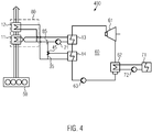
- Fig. 4 shows a third embodiment of the device according to the invention.
- the first, second, third and fourth heat exchangers 11, 12, 13, 14 are arranged in a heat transfer medium circuit with a first pump 21, wherein the through the fourth heat exchanger 14 flowing mass flow of the heat transfer medium by means of a bypass line 35 for at least partially bridging the fourth heat exchanger 14 and a valve 45 for adjusting the bridging portion of the mass flow is controllable.
- the mass flow through the fourth heat exchanger 14 for example by passing at least a portion of the mass flow of the heat transfer medium in the bypass line 35 by means of valve 45, the heat supplied to the working medium by the fourth heat exchanger 14 and / or the heat removed from the exhaust gas can be controlled.
- the two hot water circuits are connected to each other. This results in the advantage that only one hot water circulating pump 21 is needed.
- the position of the 3-way valve 45 can be changed, so that instead of the Eco 12, the preheater (VW) 14 can be bypassed.
- the variation of the position of the 3-way valve 45 is in this case according to both Verschaltungstinen Fig. 1 and 2 such as Fig. 4 possible.
- the exhaustion of the full exhaust gas potential is independent of the engine operating point. If the minimum temperature of the exhaust gas is not yet reached by the cooling through the AGWÜ alone, the valve is opened (in whole or in part), whereby the VW 14 is flowed through.
- the orifice 85 creates a flow resistance in the direct line to the AGWÜ 11 for the water to flow to the 3-way valve 45.
- a further, controllable pump can be provided to direct the mass flow direction VW 14.
- the water from the DC link is further cooled by the VW 14 and then reheated in Eco 12. See the fourth embodiment according to Fig. 5 ,
- the eco-inlet temperature is adjusted such that the flue gas is cooled to the desired temperature.
- the valve 45 is opened, as a result of which the VW 14 is increasingly bypassed. Less heat is coupled into the ORC 60, while the water entering the Eco 12 has a higher temperature, preferably close to the dew point of the exhaust gas located. As a result, a condensation of the exhaust gas is prevented.
- the advantage of this position of the 3-way valve 45 is that the AGWÜ 11 is always flowed through. This can not form local hot spots that would cause evaporation of the water.
- the interconnection has other advantages.
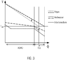
- the temperature and mass flow variable flow through the Ecos can be used to control the cooling of the exhaust gas in the Eco.
- the process can be adapted to the respective exhaust gas parameters (temperatures, mass flows) of the respective heat source. If the amount of heat in the exhaust gas is no longer sufficient for eco-operation, the exhaust gas cooling can be limited by increasing the water inlet temperature while at the same time absorbing less heat from ORC. This achieves a higher standardization since a smaller range of different AGWUs can cover the same or a wider range of heat sources (e.g., diesel and gas engines). It is also possible to set a fixed flow of AGWÜ when a heat source is to be operated in a stationary point.
- the hot water temperature in the economizer which corresponds to the mass flow of water through the economizer, can continue to increase the distance, so the temperature difference between the exhaust gas temperature and the water temperature. This reduces the area required for heat transfer in the AGWÜ. In return, the area for heat transfer from the water to the working medium increases in turn.
- the area for the evaporator and preheater is specifically cheaper than for the AGWÜ, so that there is still an economic advantage here.
- the heat exchanger surfaces for Eco and AGWÜ can be integrated in a single exhaust gas heat exchanger (see dashed line in FIG Fig. 4 ).
- the hot water circuit can be connected within the housing 80 so that only three hot water connections to the AGWÜ are necessary.
- the AGWÜ can be constructed much more compactly and the cost of pipework can be reduced.
- Fig. 5 shows a fourth embodiment of the device according to the invention.
- FIG. 5 A modification of the third embodiment according to Fig. 4 is in Fig. 5 shown as a fourth embodiment 500.
- a further controllable pump 24 is provided to direct the mass flow in the direction of the heat transfer 14 (preheater VW 14) and metering.
- the water from the DC link is further cooled by the VW 14 and then reheated in Eco 12.
- the interconnection can be further improved in order to be able to better guarantee their functionality in the use of internal combustion engines for drive purposes or continuous power generation.
- this may not lead to the maneuverability of a powered by the internal combustion engine vessel, such as overheating of the water circuit or the engine cooling water.
- the circulation pumps of the water intermediate circuit or the ORC cooling circuit must be redundantly designed as double pumps, which means additional costs but also an additional installation and maintenance.
- the interconnection according to the fifth embodiment 600 according to Fig. 6 offers this required runflat capability.
- standard components ie non-redundant pumps
- the hot water circuit and the cooling circuit as shown in the drawing, connected to each other.
- the boiling temperature of a fluid depends on the pressure level, therefore have hot water lines and their components according to the prior art, a higher pressure rating than cold water pipes, which is associated with increased costs and requirements for the material.
- the present interconnection makes it necessary because of the connecting line in a non-obvious way that both water circuits are designed for the same, higher operating pressure.
- the heat can be conducted past the ORC 60 and cooled by the cooling system, for which the valve 75 is opened.
- the pump 21 in the hot water circuit the pump 72 would take over this task in the cooling water circuit.
- the lockable valve 76 and the open 3-way valve 75 ensure that the water is not recirculated, but through the heat exchanger (AGWÜ 11 and Eco 12) is passed and dissipates the heat reliable.
- a check valve 77 is provided as shown here.
Landscapes
- Engineering & Computer Science (AREA)
- Chemical & Material Sciences (AREA)
- Combustion & Propulsion (AREA)
- Mechanical Engineering (AREA)
- General Engineering & Computer Science (AREA)
- Engine Equipment That Uses Special Cycles (AREA)
Priority Applications (8)
| Application Number | Priority Date | Filing Date | Title |
|---|---|---|---|
| DK18158794.0T DK3530890T3 (da) | 2018-02-27 | 2018-02-27 | Drev med integreret ORC |
| EP18158794.0A EP3530890B1 (fr) | 2018-02-27 | 2018-02-27 | Entraînement pourvu d'un orc intégré |
| PCT/EP2019/050211 WO2019166137A1 (fr) | 2018-02-27 | 2019-01-07 | Entraînement intégrant un cycle orc |
| JP2020568023A JP7229276B2 (ja) | 2018-02-27 | 2019-01-07 | Orcを統合した駆動装置 |
| CN201980015612.9A CN111902613A (zh) | 2018-02-27 | 2019-01-07 | 具有集成orc的驱动装置 |
| KR1020207026900A KR102615752B1 (ko) | 2018-02-27 | 2019-01-07 | 통합 orc를 구비한 구동 장치 |
| US16/976,445 US11352911B2 (en) | 2018-02-27 | 2019-01-07 | Drive having an integrated ORC |
| BR112020016793-2A BR112020016793B1 (pt) | 2018-02-27 | 2019-01-07 | Dispositivo para utilização do calor residual de um dispositivo de processo térmico e método para utilização do calor residual de um dispositivo de processo térmico |
Applications Claiming Priority (1)
| Application Number | Priority Date | Filing Date | Title |
|---|---|---|---|
| EP18158794.0A EP3530890B1 (fr) | 2018-02-27 | 2018-02-27 | Entraînement pourvu d'un orc intégré |
Publications (2)
| Publication Number | Publication Date |
|---|---|
| EP3530890A1 true EP3530890A1 (fr) | 2019-08-28 |
| EP3530890B1 EP3530890B1 (fr) | 2022-10-12 |
Family
ID=61386772
Family Applications (1)
| Application Number | Title | Priority Date | Filing Date |
|---|---|---|---|
| EP18158794.0A Active EP3530890B1 (fr) | 2018-02-27 | 2018-02-27 | Entraînement pourvu d'un orc intégré |
Country Status (7)
| Country | Link |
|---|---|
| US (1) | US11352911B2 (fr) |
| EP (1) | EP3530890B1 (fr) |
| JP (1) | JP7229276B2 (fr) |
| KR (1) | KR102615752B1 (fr) |
| CN (1) | CN111902613A (fr) |
| DK (1) | DK3530890T3 (fr) |
| WO (1) | WO2019166137A1 (fr) |
Cited By (2)
| Publication number | Priority date | Publication date | Assignee | Title |
|---|---|---|---|---|
| WO2025067602A1 (fr) * | 2023-09-28 | 2025-04-03 | Dürr Systems Ag, Stuttgart | Procédé et système pour convertir de l'énergie issue d'un processus industriel |
| EP4603683A1 (fr) * | 2024-02-14 | 2025-08-20 | Orcan Energy AG | Utilisation de différentes sources de chaleur dans des systèmes orc |
Families Citing this family (4)
| Publication number | Priority date | Publication date | Assignee | Title |
|---|---|---|---|---|
| CN111794820B (zh) * | 2020-06-09 | 2021-09-03 | 同济大学 | 一种有机朗肯循环系统 |
| CN112196634B (zh) * | 2020-10-16 | 2022-12-30 | 南昌智能新能源汽车研究院 | 基于汽车内燃机冷却循环回路的发电系统及其cfd仿真优化方法 |
| JP7725386B2 (ja) * | 2022-02-09 | 2025-08-19 | 三菱重工業株式会社 | 冷熱回収設備及び船舶 |
| WO2024219915A1 (fr) * | 2023-04-18 | 2024-10-24 | 주식회사 엘지화학 | Procédé de préparation de vapeur ou d'eau chaude à l'aide de chaleur perdue d'eau de refroidissement |
Citations (3)
| Publication number | Priority date | Publication date | Assignee | Title |
|---|---|---|---|---|
| US20150377180A1 (en) * | 2013-02-20 | 2015-12-31 | Renault S.A.S. | System for recuperating heat from the exhaust gases in an internal combustion engine, with two heat exchangers on a gas recirculation circuit |
| US20160061059A1 (en) * | 2010-12-23 | 2016-03-03 | Cummins Intellectual Property, Inc. | System and method for regulating egr cooling using a rankine cycle |
| DE102016100912A1 (de) * | 2015-01-23 | 2016-07-28 | Ford Global Technologies, Llc | Thermodynamisches System in einem Fahrzeug |
Family Cites Families (17)
| Publication number | Priority date | Publication date | Assignee | Title |
|---|---|---|---|---|
| JPS6133902U (ja) * | 1984-08-02 | 1986-03-01 | 三菱重工業株式会社 | 蓄熱発電装置 |
| JPS61152916A (ja) * | 1984-12-27 | 1986-07-11 | Toshiba Corp | バイナリ−サイクル発電プラント |
| US6571548B1 (en) * | 1998-12-31 | 2003-06-03 | Ormat Industries Ltd. | Waste heat recovery in an organic energy converter using an intermediate liquid cycle |
| JP4908383B2 (ja) * | 2006-11-24 | 2012-04-04 | ベール ゲーエムベーハー ウント コー カーゲー | 少なくとも1つの膨張装置を駆動するための有機ランキンサイクル循環を備えたシステム及び膨張装置を駆動するための熱交換器並びに少なくとも1つの膨張装置を運転するための方法 |
| JP2008255923A (ja) * | 2007-04-06 | 2008-10-23 | Sanden Corp | 内燃機関の廃熱利用装置 |
| DE102007041944B3 (de) * | 2007-09-04 | 2009-02-19 | Gesellschaft für Motoren und Kraftanlagen mbH | Vorrichtung zur Energieumwandlung, Kraft-Wärme-Kopplungsanlage mit einer derartigen Vorrichtung und Verfahren zum Betreiben einer ORC-Anlage |
| GB2457266B (en) * | 2008-02-07 | 2012-12-26 | Univ City | Generating power from medium temperature heat sources |
| EP2320058B1 (fr) * | 2008-08-26 | 2015-11-25 | Sanden Corporation | Dispositif d utilisation de chaleur résiduelle pour moteur à combustion interne |
| DE102009014185B4 (de) * | 2009-03-20 | 2010-12-16 | GMK-Gesellschaft für Motoren und Kraftanlagen mbH | Vorrichtung zur Energieumwandlung nach dem ORC-Prinzip, ORC-Anlage mit einer derartigen Vorrichtung und Verfahren zur Inbetriebnahme und/oder zum Betreiben einer derartigen Vorrichtung |
| DE102010011737B4 (de) * | 2010-03-17 | 2012-06-06 | Henry Schwarz | Verfahren und Vorrichtung zur Energieumwandlung |
| DE102011009280A1 (de) * | 2011-01-25 | 2012-07-26 | Frank Eckert | Verfahren zur Einkopplung von Wärme aus unterschiedlichen Quellen in ORC-Anlagen |
| JP6070224B2 (ja) * | 2013-01-31 | 2017-02-01 | アイシン精機株式会社 | 発電装置 |
| EP3159506B1 (fr) * | 2015-10-21 | 2020-08-19 | Orcan Energy AG | Synergies fonctionnelles lors de l'integration de systeme orc dans des moteurs a combustion interne |
| DE102016217731A1 (de) * | 2016-09-16 | 2018-03-22 | Robert Bosch Gmbh | Abwärmerückgewinnungssystem |
| JP6781673B2 (ja) * | 2017-06-22 | 2020-11-04 | 株式会社神戸製鋼所 | 熱エネルギー回収装置 |
| US11401837B2 (en) * | 2017-11-03 | 2022-08-02 | Victor Juchymenko | System, apparatus and method for managing heat transfer in power generation systems |
| CN108561241A (zh) * | 2018-01-10 | 2018-09-21 | 西安交通大学 | 一种基于内燃机余热利用的发电系统 |
-
2018
- 2018-02-27 DK DK18158794.0T patent/DK3530890T3/da active
- 2018-02-27 EP EP18158794.0A patent/EP3530890B1/fr active Active
-
2019
- 2019-01-07 WO PCT/EP2019/050211 patent/WO2019166137A1/fr not_active Ceased
- 2019-01-07 US US16/976,445 patent/US11352911B2/en active Active
- 2019-01-07 JP JP2020568023A patent/JP7229276B2/ja active Active
- 2019-01-07 CN CN201980015612.9A patent/CN111902613A/zh active Pending
- 2019-01-07 KR KR1020207026900A patent/KR102615752B1/ko active Active
Patent Citations (3)
| Publication number | Priority date | Publication date | Assignee | Title |
|---|---|---|---|---|
| US20160061059A1 (en) * | 2010-12-23 | 2016-03-03 | Cummins Intellectual Property, Inc. | System and method for regulating egr cooling using a rankine cycle |
| US20150377180A1 (en) * | 2013-02-20 | 2015-12-31 | Renault S.A.S. | System for recuperating heat from the exhaust gases in an internal combustion engine, with two heat exchangers on a gas recirculation circuit |
| DE102016100912A1 (de) * | 2015-01-23 | 2016-07-28 | Ford Global Technologies, Llc | Thermodynamisches System in einem Fahrzeug |
Cited By (3)
| Publication number | Priority date | Publication date | Assignee | Title |
|---|---|---|---|---|
| WO2025067602A1 (fr) * | 2023-09-28 | 2025-04-03 | Dürr Systems Ag, Stuttgart | Procédé et système pour convertir de l'énergie issue d'un processus industriel |
| EP4603683A1 (fr) * | 2024-02-14 | 2025-08-20 | Orcan Energy AG | Utilisation de différentes sources de chaleur dans des systèmes orc |
| WO2025171905A1 (fr) * | 2024-02-14 | 2025-08-21 | Orcan Energy Ag | Utilisation de différentes sources de chaleur dans des systèmes orc |
Also Published As
| Publication number | Publication date |
|---|---|
| CN111902613A (zh) | 2020-11-06 |
| BR112020016793A2 (pt) | 2020-12-15 |
| EP3530890B1 (fr) | 2022-10-12 |
| KR102615752B1 (ko) | 2023-12-19 |
| US11352911B2 (en) | 2022-06-07 |
| WO2019166137A1 (fr) | 2019-09-06 |
| KR20200122361A (ko) | 2020-10-27 |
| JP2021515138A (ja) | 2021-06-17 |
| JP7229276B2 (ja) | 2023-02-27 |
| US20210003039A1 (en) | 2021-01-07 |
| DK3530890T3 (da) | 2023-01-16 |
Similar Documents
| Publication | Publication Date | Title |
|---|---|---|
| EP3530890B1 (fr) | Entraînement pourvu d'un orc intégré | |
| EP3159506B1 (fr) | Synergies fonctionnelles lors de l'integration de systeme orc dans des moteurs a combustion interne | |
| DE60315823T2 (de) | Verfahren und einrichtung zur stromerzeugung aus der im kern mindestens eines hochtemperatur-kernreaktors erzeugten wärme | |
| DE102014019684A1 (de) | Anordnung zur Umwandlung thermischer Energie aus Verlustwärme einer Verbrennungskraftmaschine | |
| EP2992194A1 (fr) | Circuit de refroidissement | |
| WO2015197456A1 (fr) | Système de refroidissement et de récupération d'énergie | |
| EP3006682A1 (fr) | Dispositif et procédé de fonctionnement d'une station de transmission thermique | |
| DE102016115513B4 (de) | Verbrennungsmotorvorwärmvorrichtung und Vorwärmverfahren für Verbrennungsmotor | |
| EP3447256B1 (fr) | Système de refroidissement pour un fluide provenant d'une installation produisant de la chaleur | |
| WO2008031716A2 (fr) | Procédé à circuit de vapeur à utilisation d'énergie améliorée | |
| DE69711608T2 (de) | Methode und einrichtung zur rückgewinnung von wärme aus der ladeluft eines motors | |
| DE10155508C5 (de) | Verfahren und Vorrichtung zur Erzeugung von elektrischer Energie | |
| WO2015067434A1 (fr) | Procédé permettant de faire fonctionner un système de récupération d'énergie à partir d'un flux de chaleur perdue d'un moteur à combustion interne | |
| DE102008020637B4 (de) | Warmwasserversorgungsanlage mit einem Warmwasserspeicher | |
| EP2108813A1 (fr) | Dispositif de refroidissement ou de chauffage d'un moteur à combustion interne | |
| DE102016222687B4 (de) | Wärmebereitstellungseinrichtung | |
| DE102018205130A1 (de) | Verfahren zum Erwärmen eines Antriebs eines Hybridfahrzeugs sowie Vorwärmeinrichtung | |
| WO2016162118A1 (fr) | Dispositif de récupération de chaleur résiduelle et procédé servant faire fonctionner ledit dispositif | |
| DE102020002880A1 (de) | Wärmemanagementsystem, Verfahren zum Kühlen eines Kondensators eines Abwärmerückgewinnungssystems und zugehörige Einrichtungen | |
| EP3943819B1 (fr) | Système de ventilation à air chaud à récupération de chaleur | |
| DE102017200887A1 (de) | Anordnung mit einem System zur Durchführung eines thermodynamischen Kreisprozesses und einer Brennkraftmaschine, sowie Verfahren zum Betreiben einer solchen Anordnung | |
| WO2025171905A1 (fr) | Utilisation de différentes sources de chaleur dans des systèmes orc | |
| DE102018213086B4 (de) | Geteiltes Kühlsystem für Brennkraftmaschine | |
| DE102024209406A1 (de) | Thermomanagementsystem für ein Kraftfahrzeug, Wärmepumpe, Kraftfahrzeug sowie Verfahren zur Regelung eines Thermomanagementsystems | |
| DE102017209827A1 (de) | Brennkraftmaschine und Kraftfahrzeug |
Legal Events
| Date | Code | Title | Description |
|---|---|---|---|
| PUAI | Public reference made under article 153(3) epc to a published international application that has entered the european phase |
Free format text: ORIGINAL CODE: 0009012 |
|
| STAA | Information on the status of an ep patent application or granted ep patent |
Free format text: STATUS: THE APPLICATION HAS BEEN PUBLISHED |
|
| AK | Designated contracting states |
Kind code of ref document: A1 Designated state(s): AL AT BE BG CH CY CZ DE DK EE ES FI FR GB GR HR HU IE IS IT LI LT LU LV MC MK MT NL NO PL PT RO RS SE SI SK SM TR |
|
| AX | Request for extension of the european patent |
Extension state: BA ME |
|
| STAA | Information on the status of an ep patent application or granted ep patent |
Free format text: STATUS: REQUEST FOR EXAMINATION WAS MADE |
|
| 17P | Request for examination filed |
Effective date: 20200212 |
|
| RBV | Designated contracting states (corrected) |
Designated state(s): AL AT BE BG CH CY CZ DE DK EE ES FI FR GB GR HR HU IE IS IT LI LT LU LV MC MK MT NL NO PL PT RO RS SE SI SK SM TR |
|
| GRAP | Despatch of communication of intention to grant a patent |
Free format text: ORIGINAL CODE: EPIDOSNIGR1 |
|
| STAA | Information on the status of an ep patent application or granted ep patent |
Free format text: STATUS: GRANT OF PATENT IS INTENDED |
|
| INTG | Intention to grant announced |
Effective date: 20220422 |
|
| RIN1 | Information on inventor provided before grant (corrected) |
Inventor name: AUMANN, RICHARD Inventor name: WALTER, DANIELA Inventor name: SPRINGER, JENS-PATRICK Inventor name: LANGER, ROY Inventor name: SCHUSTER, ANDREAS |
|
| GRAS | Grant fee paid |
Free format text: ORIGINAL CODE: EPIDOSNIGR3 |
|
| GRAA | (expected) grant |
Free format text: ORIGINAL CODE: 0009210 |
|
| STAA | Information on the status of an ep patent application or granted ep patent |
Free format text: STATUS: THE PATENT HAS BEEN GRANTED |
|
| AK | Designated contracting states |
Kind code of ref document: B1 Designated state(s): AL AT BE BG CH CY CZ DE DK EE ES FI FR GB GR HR HU IE IS IT LI LT LU LV MC MK MT NL NO PL PT RO RS SE SI SK SM TR |
|
| REG | Reference to a national code |
Ref country code: GB Ref legal event code: FG4D Free format text: NOT ENGLISH |
|
| REG | Reference to a national code |
Ref country code: CH Ref legal event code: EP |
|
| REG | Reference to a national code |
Ref country code: DE Ref legal event code: R096 Ref document number: 502018010804 Country of ref document: DE |
|
| REG | Reference to a national code |
Ref country code: IE Ref legal event code: FG4D Free format text: LANGUAGE OF EP DOCUMENT: GERMAN |
|
| REG | Reference to a national code |
Ref country code: AT Ref legal event code: REF Ref document number: 1524302 Country of ref document: AT Kind code of ref document: T Effective date: 20221115 |
|
| REG | Reference to a national code |
Ref country code: NL Ref legal event code: FP |
|
| REG | Reference to a national code |
Ref country code: DK Ref legal event code: T3 Effective date: 20230111 |
|
| REG | Reference to a national code |
Ref country code: SE Ref legal event code: TRGR |
|
| REG | Reference to a national code |
Ref country code: LT Ref legal event code: MG9D |
|
| PG25 | Lapsed in a contracting state [announced via postgrant information from national office to epo] |
Ref country code: PT Free format text: LAPSE BECAUSE OF FAILURE TO SUBMIT A TRANSLATION OF THE DESCRIPTION OR TO PAY THE FEE WITHIN THE PRESCRIBED TIME-LIMIT Effective date: 20230213 Ref country code: NO Free format text: LAPSE BECAUSE OF FAILURE TO SUBMIT A TRANSLATION OF THE DESCRIPTION OR TO PAY THE FEE WITHIN THE PRESCRIBED TIME-LIMIT Effective date: 20230112 Ref country code: LT Free format text: LAPSE BECAUSE OF FAILURE TO SUBMIT A TRANSLATION OF THE DESCRIPTION OR TO PAY THE FEE WITHIN THE PRESCRIBED TIME-LIMIT Effective date: 20221012 Ref country code: FI Free format text: LAPSE BECAUSE OF FAILURE TO SUBMIT A TRANSLATION OF THE DESCRIPTION OR TO PAY THE FEE WITHIN THE PRESCRIBED TIME-LIMIT Effective date: 20221012 Ref country code: ES Free format text: LAPSE BECAUSE OF FAILURE TO SUBMIT A TRANSLATION OF THE DESCRIPTION OR TO PAY THE FEE WITHIN THE PRESCRIBED TIME-LIMIT Effective date: 20221012 |
|
| PG25 | Lapsed in a contracting state [announced via postgrant information from national office to epo] |
Ref country code: RS Free format text: LAPSE BECAUSE OF FAILURE TO SUBMIT A TRANSLATION OF THE DESCRIPTION OR TO PAY THE FEE WITHIN THE PRESCRIBED TIME-LIMIT Effective date: 20221012 Ref country code: PL Free format text: LAPSE BECAUSE OF FAILURE TO SUBMIT A TRANSLATION OF THE DESCRIPTION OR TO PAY THE FEE WITHIN THE PRESCRIBED TIME-LIMIT Effective date: 20221012 Ref country code: LV Free format text: LAPSE BECAUSE OF FAILURE TO SUBMIT A TRANSLATION OF THE DESCRIPTION OR TO PAY THE FEE WITHIN THE PRESCRIBED TIME-LIMIT Effective date: 20221012 Ref country code: IS Free format text: LAPSE BECAUSE OF FAILURE TO SUBMIT A TRANSLATION OF THE DESCRIPTION OR TO PAY THE FEE WITHIN THE PRESCRIBED TIME-LIMIT Effective date: 20230212 Ref country code: HR Free format text: LAPSE BECAUSE OF FAILURE TO SUBMIT A TRANSLATION OF THE DESCRIPTION OR TO PAY THE FEE WITHIN THE PRESCRIBED TIME-LIMIT Effective date: 20221012 Ref country code: GR Free format text: LAPSE BECAUSE OF FAILURE TO SUBMIT A TRANSLATION OF THE DESCRIPTION OR TO PAY THE FEE WITHIN THE PRESCRIBED TIME-LIMIT Effective date: 20230113 |
|
| REG | Reference to a national code |
Ref country code: DE Ref legal event code: R097 Ref document number: 502018010804 Country of ref document: DE |
|
| PG25 | Lapsed in a contracting state [announced via postgrant information from national office to epo] |
Ref country code: SM Free format text: LAPSE BECAUSE OF FAILURE TO SUBMIT A TRANSLATION OF THE DESCRIPTION OR TO PAY THE FEE WITHIN THE PRESCRIBED TIME-LIMIT Effective date: 20221012 Ref country code: RO Free format text: LAPSE BECAUSE OF FAILURE TO SUBMIT A TRANSLATION OF THE DESCRIPTION OR TO PAY THE FEE WITHIN THE PRESCRIBED TIME-LIMIT Effective date: 20221012 Ref country code: EE Free format text: LAPSE BECAUSE OF FAILURE TO SUBMIT A TRANSLATION OF THE DESCRIPTION OR TO PAY THE FEE WITHIN THE PRESCRIBED TIME-LIMIT Effective date: 20221012 Ref country code: CZ Free format text: LAPSE BECAUSE OF FAILURE TO SUBMIT A TRANSLATION OF THE DESCRIPTION OR TO PAY THE FEE WITHIN THE PRESCRIBED TIME-LIMIT Effective date: 20221012 |
|
| PLBE | No opposition filed within time limit |
Free format text: ORIGINAL CODE: 0009261 |
|
| STAA | Information on the status of an ep patent application or granted ep patent |
Free format text: STATUS: NO OPPOSITION FILED WITHIN TIME LIMIT |
|
| PG25 | Lapsed in a contracting state [announced via postgrant information from national office to epo] |
Ref country code: SK Free format text: LAPSE BECAUSE OF FAILURE TO SUBMIT A TRANSLATION OF THE DESCRIPTION OR TO PAY THE FEE WITHIN THE PRESCRIBED TIME-LIMIT Effective date: 20221012 Ref country code: AL Free format text: LAPSE BECAUSE OF FAILURE TO SUBMIT A TRANSLATION OF THE DESCRIPTION OR TO PAY THE FEE WITHIN THE PRESCRIBED TIME-LIMIT Effective date: 20221012 |
|
| 26N | No opposition filed |
Effective date: 20230713 |
|
| PG25 | Lapsed in a contracting state [announced via postgrant information from national office to epo] |
Ref country code: MC Free format text: LAPSE BECAUSE OF FAILURE TO SUBMIT A TRANSLATION OF THE DESCRIPTION OR TO PAY THE FEE WITHIN THE PRESCRIBED TIME-LIMIT Effective date: 20221012 |
|
| REG | Reference to a national code |
Ref country code: CH Ref legal event code: PL |
|
| REG | Reference to a national code |
Ref country code: BE Ref legal event code: MM Effective date: 20230228 |
|
| PG25 | Lapsed in a contracting state [announced via postgrant information from national office to epo] |
Ref country code: LU Free format text: LAPSE BECAUSE OF NON-PAYMENT OF DUE FEES Effective date: 20230227 Ref country code: LI Free format text: LAPSE BECAUSE OF NON-PAYMENT OF DUE FEES Effective date: 20230228 Ref country code: CH Free format text: LAPSE BECAUSE OF NON-PAYMENT OF DUE FEES Effective date: 20230228 |
|
| PG25 | Lapsed in a contracting state [announced via postgrant information from national office to epo] |
Ref country code: SI Free format text: LAPSE BECAUSE OF FAILURE TO SUBMIT A TRANSLATION OF THE DESCRIPTION OR TO PAY THE FEE WITHIN THE PRESCRIBED TIME-LIMIT Effective date: 20221012 |
|
| REG | Reference to a national code |
Ref country code: IE Ref legal event code: MM4A |
|
| PG25 | Lapsed in a contracting state [announced via postgrant information from national office to epo] |
Ref country code: IE Free format text: LAPSE BECAUSE OF NON-PAYMENT OF DUE FEES Effective date: 20230227 |
|
| PG25 | Lapsed in a contracting state [announced via postgrant information from national office to epo] |
Ref country code: BE Free format text: LAPSE BECAUSE OF NON-PAYMENT OF DUE FEES Effective date: 20230228 |
|
| REG | Reference to a national code |
Ref country code: AT Ref legal event code: MM01 Ref document number: 1524302 Country of ref document: AT Kind code of ref document: T Effective date: 20230227 |
|
| PG25 | Lapsed in a contracting state [announced via postgrant information from national office to epo] |
Ref country code: AT Free format text: LAPSE BECAUSE OF NON-PAYMENT OF DUE FEES Effective date: 20230227 |
|
| PG25 | Lapsed in a contracting state [announced via postgrant information from national office to epo] |
Ref country code: AT Free format text: LAPSE BECAUSE OF NON-PAYMENT OF DUE FEES Effective date: 20230227 |
|
| PG25 | Lapsed in a contracting state [announced via postgrant information from national office to epo] |
Ref country code: BG Free format text: LAPSE BECAUSE OF FAILURE TO SUBMIT A TRANSLATION OF THE DESCRIPTION OR TO PAY THE FEE WITHIN THE PRESCRIBED TIME-LIMIT Effective date: 20221012 |
|
| PG25 | Lapsed in a contracting state [announced via postgrant information from national office to epo] |
Ref country code: BG Free format text: LAPSE BECAUSE OF FAILURE TO SUBMIT A TRANSLATION OF THE DESCRIPTION OR TO PAY THE FEE WITHIN THE PRESCRIBED TIME-LIMIT Effective date: 20221012 |
|
| PG25 | Lapsed in a contracting state [announced via postgrant information from national office to epo] |
Ref country code: CY Free format text: LAPSE BECAUSE OF FAILURE TO SUBMIT A TRANSLATION OF THE DESCRIPTION OR TO PAY THE FEE WITHIN THE PRESCRIBED TIME-LIMIT; INVALID AB INITIO Effective date: 20180227 |
|
| PG25 | Lapsed in a contracting state [announced via postgrant information from national office to epo] |
Ref country code: HU Free format text: LAPSE BECAUSE OF FAILURE TO SUBMIT A TRANSLATION OF THE DESCRIPTION OR TO PAY THE FEE WITHIN THE PRESCRIBED TIME-LIMIT; INVALID AB INITIO Effective date: 20180227 |
|
| PG25 | Lapsed in a contracting state [announced via postgrant information from national office to epo] |
Ref country code: TR Free format text: LAPSE BECAUSE OF FAILURE TO SUBMIT A TRANSLATION OF THE DESCRIPTION OR TO PAY THE FEE WITHIN THE PRESCRIBED TIME-LIMIT Effective date: 20221012 |
|
| PGFP | Annual fee paid to national office [announced via postgrant information from national office to epo] |
Ref country code: NL Payment date: 20260228 Year of fee payment: 9 |
|
| PGFP | Annual fee paid to national office [announced via postgrant information from national office to epo] |
Ref country code: SE Payment date: 20260228 Year of fee payment: 9 |
|
| PGFP | Annual fee paid to national office [announced via postgrant information from national office to epo] |
Ref country code: GB Payment date: 20260226 Year of fee payment: 9 |
|
| PGFP | Annual fee paid to national office [announced via postgrant information from national office to epo] |
Ref country code: DK Payment date: 20260225 Year of fee payment: 9 Ref country code: DE Payment date: 20260218 Year of fee payment: 9 |
|
| PGFP | Annual fee paid to national office [announced via postgrant information from national office to epo] |
Ref country code: IT Payment date: 20260227 Year of fee payment: 9 |
|
| PGFP | Annual fee paid to national office [announced via postgrant information from national office to epo] |
Ref country code: FR Payment date: 20260225 Year of fee payment: 9 |