EP3530929A1 - Système de gestion de compresseur de moteur de turbine à gaz - Google Patents
Système de gestion de compresseur de moteur de turbine à gaz Download PDFInfo
- Publication number
- EP3530929A1 EP3530929A1 EP19154176.2A EP19154176A EP3530929A1 EP 3530929 A1 EP3530929 A1 EP 3530929A1 EP 19154176 A EP19154176 A EP 19154176A EP 3530929 A1 EP3530929 A1 EP 3530929A1
- Authority
- EP
- European Patent Office
- Prior art keywords
- compressor
- pressure compressor
- high pressure
- low pressure
- low
- Prior art date
- Legal status (The legal status is an assumption and is not a legal conclusion. Google has not performed a legal analysis and makes no representation as to the accuracy of the status listed.)
- Granted
Links
Images


Classifications
-
- F—MECHANICAL ENGINEERING; LIGHTING; HEATING; WEAPONS; BLASTING
- F04—POSITIVE - DISPLACEMENT MACHINES FOR LIQUIDS; PUMPS FOR LIQUIDS OR ELASTIC FLUIDS
- F04D—NON-POSITIVE-DISPLACEMENT PUMPS
- F04D27/00—Control, e.g. regulation, of pumps, pumping installations or pumping systems specially adapted for elastic fluids
- F04D27/02—Surge control
-
- F—MECHANICAL ENGINEERING; LIGHTING; HEATING; WEAPONS; BLASTING
- F02—COMBUSTION ENGINES; HOT-GAS OR COMBUSTION-PRODUCT ENGINE PLANTS
- F02C—GAS-TURBINE PLANTS; AIR INTAKES FOR JET-PROPULSION PLANTS; CONTROLLING FUEL SUPPLY IN AIR-BREATHING JET-PROPULSION PLANTS
- F02C3/00—Gas-turbine plants characterised by the use of combustion products as the working fluid
- F02C3/04—Gas-turbine plants characterised by the use of combustion products as the working fluid having a turbine driving a compressor
-
- F—MECHANICAL ENGINEERING; LIGHTING; HEATING; WEAPONS; BLASTING
- F02—COMBUSTION ENGINES; HOT-GAS OR COMBUSTION-PRODUCT ENGINE PLANTS
- F02C—GAS-TURBINE PLANTS; AIR INTAKES FOR JET-PROPULSION PLANTS; CONTROLLING FUEL SUPPLY IN AIR-BREATHING JET-PROPULSION PLANTS
- F02C9/00—Controlling gas-turbine plants; Controlling fuel supply in air- breathing jet-propulsion plants
- F02C9/16—Control of working fluid flow
- F02C9/18—Control of working fluid flow by bleeding, bypassing or acting on variable working fluid interconnections between turbines or compressors or their stages
-
- F—MECHANICAL ENGINEERING; LIGHTING; HEATING; WEAPONS; BLASTING
- F02—COMBUSTION ENGINES; HOT-GAS OR COMBUSTION-PRODUCT ENGINE PLANTS
- F02C—GAS-TURBINE PLANTS; AIR INTAKES FOR JET-PROPULSION PLANTS; CONTROLLING FUEL SUPPLY IN AIR-BREATHING JET-PROPULSION PLANTS
- F02C9/00—Controlling gas-turbine plants; Controlling fuel supply in air- breathing jet-propulsion plants
- F02C9/16—Control of working fluid flow
- F02C9/20—Control of working fluid flow by throttling; by adjusting vanes
- F02C9/22—Control of working fluid flow by throttling; by adjusting vanes by adjusting turbine vanes
-
- F—MECHANICAL ENGINEERING; LIGHTING; HEATING; WEAPONS; BLASTING
- F02—COMBUSTION ENGINES; HOT-GAS OR COMBUSTION-PRODUCT ENGINE PLANTS
- F02K—JET-PROPULSION PLANTS
- F02K3/00—Plants including a gas turbine driving a compressor or a ducted fan
- F02K3/02—Plants including a gas turbine driving a compressor or a ducted fan in which part of the working fluid by-passes the turbine and combustion chamber
- F02K3/04—Plants including a gas turbine driving a compressor or a ducted fan in which part of the working fluid by-passes the turbine and combustion chamber the plant including ducted fans, i.e. fans with high volume, low pressure outputs, for augmenting the jet thrust, e.g. of double-flow type
- F02K3/06—Plants including a gas turbine driving a compressor or a ducted fan in which part of the working fluid by-passes the turbine and combustion chamber the plant including ducted fans, i.e. fans with high volume, low pressure outputs, for augmenting the jet thrust, e.g. of double-flow type with front fan
-
- F—MECHANICAL ENGINEERING; LIGHTING; HEATING; WEAPONS; BLASTING
- F04—POSITIVE - DISPLACEMENT MACHINES FOR LIQUIDS; PUMPS FOR LIQUIDS OR ELASTIC FLUIDS
- F04D—NON-POSITIVE-DISPLACEMENT PUMPS
- F04D27/00—Control, e.g. regulation, of pumps, pumping installations or pumping systems specially adapted for elastic fluids
- F04D27/009—Control, e.g. regulation, of pumps, pumping installations or pumping systems specially adapted for elastic fluids by bleeding, by passing or recycling fluid
-
- F—MECHANICAL ENGINEERING; LIGHTING; HEATING; WEAPONS; BLASTING
- F04—POSITIVE - DISPLACEMENT MACHINES FOR LIQUIDS; PUMPS FOR LIQUIDS OR ELASTIC FLUIDS
- F04D—NON-POSITIVE-DISPLACEMENT PUMPS
- F04D29/00—Details, component parts, or accessories
- F04D29/40—Casings; Connections of working fluid
- F04D29/403—Casings; Connections of working fluid especially adapted for elastic fluid pumps
-
- F—MECHANICAL ENGINEERING; LIGHTING; HEATING; WEAPONS; BLASTING
- F02—COMBUSTION ENGINES; HOT-GAS OR COMBUSTION-PRODUCT ENGINE PLANTS
- F02C—GAS-TURBINE PLANTS; AIR INTAKES FOR JET-PROPULSION PLANTS; CONTROLLING FUEL SUPPLY IN AIR-BREATHING JET-PROPULSION PLANTS
- F02C9/00—Controlling gas-turbine plants; Controlling fuel supply in air- breathing jet-propulsion plants
- F02C9/16—Control of working fluid flow
-
- F—MECHANICAL ENGINEERING; LIGHTING; HEATING; WEAPONS; BLASTING
- F05—INDEXING SCHEMES RELATING TO ENGINES OR PUMPS IN VARIOUS SUBCLASSES OF CLASSES F01-F04
- F05D—INDEXING SCHEME FOR ASPECTS RELATING TO NON-POSITIVE-DISPLACEMENT MACHINES OR ENGINES, GAS-TURBINES OR JET-PROPULSION PLANTS
- F05D2220/00—Application
- F05D2220/30—Application in turbines
- F05D2220/32—Application in turbines in gas turbines
-
- F—MECHANICAL ENGINEERING; LIGHTING; HEATING; WEAPONS; BLASTING
- F05—INDEXING SCHEMES RELATING TO ENGINES OR PUMPS IN VARIOUS SUBCLASSES OF CLASSES F01-F04
- F05D—INDEXING SCHEME FOR ASPECTS RELATING TO NON-POSITIVE-DISPLACEMENT MACHINES OR ENGINES, GAS-TURBINES OR JET-PROPULSION PLANTS
- F05D2260/00—Function
- F05D2260/40—Transmission of power
- F05D2260/403—Transmission of power through the shape of the drive components
- F05D2260/4031—Transmission of power through the shape of the drive components as in toothed gearing
- F05D2260/40311—Transmission of power through the shape of the drive components as in toothed gearing of the epicyclical, planetary or differential type
-
- F—MECHANICAL ENGINEERING; LIGHTING; HEATING; WEAPONS; BLASTING
- F05—INDEXING SCHEMES RELATING TO ENGINES OR PUMPS IN VARIOUS SUBCLASSES OF CLASSES F01-F04
- F05D—INDEXING SCHEME FOR ASPECTS RELATING TO NON-POSITIVE-DISPLACEMENT MACHINES OR ENGINES, GAS-TURBINES OR JET-PROPULSION PLANTS
- F05D2270/00—Control
- F05D2270/01—Purpose of the control system
- F05D2270/10—Purpose of the control system to cope with, or avoid, compressor flow instabilities
- F05D2270/101—Compressor surge or stall
-
- F—MECHANICAL ENGINEERING; LIGHTING; HEATING; WEAPONS; BLASTING
- F05—INDEXING SCHEMES RELATING TO ENGINES OR PUMPS IN VARIOUS SUBCLASSES OF CLASSES F01-F04
- F05D—INDEXING SCHEME FOR ASPECTS RELATING TO NON-POSITIVE-DISPLACEMENT MACHINES OR ENGINES, GAS-TURBINES OR JET-PROPULSION PLANTS
- F05D2270/00—Control
- F05D2270/30—Control parameters, e.g. input parameters
- F05D2270/301—Pressure
Definitions
- the present disclosure concerns a system for management of a gas turbine engine compressor.
- Gas turbines typically comprise compressors of either an axial or a centrifugal type. In either case (though particularly for axial compressors), compressor variable geometry is desirable in order to allow the compressor to operate at a wide range of compressor rotational speeds, air mass flow rates and compressor loads.
- compressor variable geometry comprises one or both of compressor bleeds and variable guide vanes (VGVs).
- Compressor bleeds allow a portion of air downstream of one or more compressor stages to be dumped overboard through a bleed valve, rather than passed to a downstream component, thereby reducing compressor pressure ratio.
- variable guide vanes adjust the angle of oncoming air to a downstream rotor stage, to similarly reduce the compressor pressure ratio for a given rotational speed.
- Compressor variable geometry is conventionally controlled on the basis of one or more compressor parameters such as pressure ratio, working gas flow temperature and / or compressor rotational speed.
- a "schedule" is used that relates a given sensed or calculated compressor parameter, and a corresponding desired variable geometry setting for that compressor. In many cases, different schedules are provided for different operating conditions, such as steady state and transient conditions.
- a gas turbine engine compressor operating system comprising: a low pressure compressor and a high pressure compressor, the low and high pressure compressors being driven by low and high pressure shafts respectively, the high pressure compressor being provided downstream in core mass flow of the low pressure compressor;
- the compressor operating system comprising: a controller configured to control a variable geometry actuator of the low pressure compressor, the controller being configured to control the variable geometry actuator on the basis of low pressure compressor rotational speed and a high pressure compressor operating parameter.
- the low pressure compressor is controlled on the basis of both low pressure compressor speed and one or more high pressure compressor parameters.
- the low pressure compressor rotational speed may comprise a corrected low pressure compressor rotational speed.
- the high pressure compressor operating parameter may comprise one or more of high pressure compressor mass flow rate, high pressure compressor pressure ratio, high pressure compressor rotational speed, high pressure compressor corrected rotational speed and high pressure compressor variable inlet guide vane angle.
- the high pressure compressor operating parameter may comprise a parameter indicative of the high pressure compressor mass flow rate or pressure ratio.
- the gas turbine engine may comprise a geared turbofan comprising a fan coupled to an output of a reduction gearbox.
- An input of the reduction gearbox may be coupled to the low pressure shaft, and a low pressure turbine may be coupled to the low pressure shaft.
- variable geometry actuator may comprise one or both of a variable inlet guide vane and a bleed valve.
- the controller may be configured to operate the low pressure compressor on the basis of one of a first schedule and a second schedule in accordance with the high pressure compressor operating parameter.
- the low pressure compressor may be operated in accordance with the first schedule where the high pressure compressor is at a relatively low pressure ratio, and may be operated in accordance with the second schedule where the high pressure compressor is at a relatively high pressure ratio.
- the second schedule may comprise a more open inlet guide vane position for a given low pressure compressor rotational speed than the first schedule.
- the second schedule may comprise a more closed bleed valve position for a given low pressure compressor rotational speed than the first schedule.
- the controller may be configured to determine a correction factor to the low pressure compressor control schedule based on the high pressure compressor parameter.
- the correction factor may be proportional to one or more of the high pressure compressor mass flow, the high pressure compressor pressure ratio, or a parameter indicative of the high pressure compressor pressure ratio.
- a gas turbine engine compressor of a gas turbine engine comprising: a low pressure compressor and a high pressure compressor, the low and high pressure compressors being driven by low and high pressure shafts respectively, the high pressure compressor being provided downstream in core mass flow of the low pressure compressor; the method comprising:
- a gas turbine engine comprising a compressor operating system according to the first aspect.
- a feature described in relation to any one of the above aspects may be applied mutatis mutandis to any other aspect.
- any feature described herein may be applied to any aspect and/or combined with any other feature described herein.
- a gas turbine engine is generally indicated at 10, having a principal and rotational axis 11.
- the engine 10 comprises, in axial flow series, an air intake 12, a propulsive fan 23, a gearbox 30, a low pressure compressor (LPC) 14, a high-pressure compressor (HPC) 15, combustion equipment 16, a high-pressure turbine 17, a low-pressure turbine 19 and an exhaust nozzle 20.
- a nacelle 21 generally surrounds the engine 10 and defines the intake 12.
- the gas turbine engine 10 works in the conventional manner so that air entering the intake 12 is accelerated and compressed by the fan 23 to produce two air flows: a first air flow A into the engine core and a second air flow B which passes through a bypass duct 22 to provide propulsive thrust.
- the first and second airflows A, B split at a generally annular splitter 40, for example at the leading edge of the generally annular splitter 40 at a generally circular stagnation line.
- the engine core includes the LPC 14 which compresses the air flow directed into it before delivering that air to the HPC 15 where further compression takes place.
- the compressed air exhausted from the HPC 15 is directed into the combustion equipment 16 where it is mixed with fuel and the mixture combusted.
- the resultant hot combustion products then expand through, and thereby drive the high pressure turbine 17 and the low pressure turbine 19 before being exhausted through the nozzle 20 to provide additional propulsive thrust.
- the LPC 14 is driven by the low pressure turbine 19 by a low pressure shaft 26.
- the HPC 15 is driven by the high pressure turbine 17 by a high pressure shaft 27.
- the low pressure shaft 26 also drives the fan 23 via the gearbox 30.
- the gearbox 30 is a reduction gearbox in that it gears down the rate of rotation of the fan 23 by comparison with the low pressure compressor 14 and low pressure turbine 19.
- the gearbox 30 may be any suitable type of gearbox, such as an epicyclic planetary gearbox (having a static ring gear, rotating and orbiting planet gears supported by a planet carrier and a rotating sun gear) or a star gearbox. Additionally or alternatively the gearbox 30 may drive additional and/or alternative components (e.g. a further compressor).
- an epicyclic planetary gearbox having a static ring gear, rotating and orbiting planet gears supported by a planet carrier and a rotating sun gear
- a star gearbox may drive additional and/or alternative components (e.g. a further compressor).
- the low and high pressure compressors 14, 15, high and low pressure turbines 17, 19, low and high pressure shafts 26, 27, and the combustor 16 may all be said to be part of the engine core.
- the geared turbofan of figure 1 has different characteristics compared to "direct drive” turbofans, in which the low pressure turbine is directly coupled to the fan.
- the low pressure turbine 19 and low pressure compressor 15 spin at a higher rate for a given fan 23 rotational speed.
- This higher rotational speed in addition to the additional rotational mass of the rotating elements of the gearbox 30, may result in the low pressure spool (comprising the low pressure turbine 19, shaft 26, compressor 14, gearbox 30 and fan 23) to have a relatively high rotational inertia compared to direct drive engines of a similar size.
- high pressure spool (comprising the HPC 15, shaft 27 and turbine 17) is unaffected by this change. This has an effect on operability of the low and high pressure compressors 14, 15.
- the HPC 15 accelerates relatively rapidly, whereas the LPC 14 accelerates relatively slowly. This results in a relatively low pressure ratio across the LPC 14 during accelerations due to two related effects. Firstly, the LPC 14 rotates relatively slowly, resulting in a low pressure ratio being developed. Secondly, the HPC 15 reaches high speeds more quickly, resulting in a relatively high pressure ratio. This high pressure ratio across the HPC 15 "sucks" air from the LPC exit, resulting in a lower pressure rise across the LPC 14, and so a low load on the LPC.
- Each compressor 14, 15 comprises variable geometry actuators in the form of variable inlet guide vanes (IGVs) 32, 36, and bleed valves 34, 38.
- the IGVs 32, 36 are of conventional construction, and are configured to pivot about a generally radially extending axis, to adjust the angle of attack ( ⁇ ) of air impinging on downstream compressor rotor stages.
- the IGVs 32, 36 are located toward the front of a respective compressor 14, 15, prior to the first rotor stage, and optionally for one or more subsequent stages.
- the IGVs 32, 36 are moveable between an "open” position, in which a leading edge of the respective IGV 32, 36 is substantially parallel to the engine axis 9, and the angle of attack of the downstream rotor blades is relatively high, and a "closed” position, in which the leading edge is turned further toward a circumferential direction, away from the engine axis 9, and the angle of attack of the downstream rotor blades is relatively low.
- the bleed valves 34, 38 are valves, which can open to allow core air to escape from a respective compressor 14, 15, or close to keep core air within the compressor 14, 15, for further compression or combustion in downstream components.
- the bleed valves 34, 38 are typically located toward the rear of the compressors 14, 15. Opening of a bleed valve 34, 38, consequently typically reduces the pressure ratio of that compressor 14, 15, while closing the valve 34, 38 raises the pressure.
- the IGVs 32, 36 and bleed valves 34, 38 are controlled in accordance with a compressor control schedule.
- the schedule takes into account current conditions of the compressor being controlled (e.g. low pressure compressor 14 rotational speed N1 for the LPC control schedule), as well as environmental conditions such as inlet temperature T24.
- the vanes 32, 36 and valves 34, 38 are then controlled on the basis of the current rotational speed N1, corrected for LPC 14 inlet temperature T24.
- the IGVs are closed at low compressor speed N1, and open at higher speeds. By closing the IGVs 32, 34 at low speeds, blade angle of attack ⁇ and mass flow W is reduced, to ensure that the compressor blades do not stall.
- the difference between the current pressure ratio P26/P24 of the compressor 14 and the pressure ratio P26/P24 at which the compressor will stall or surge is known as the "surge margin".
- the schedule attempts to maintain the compressor ratio below the surge margin at all times, but reasonably close, so as to maintain high efficiency.
- the valves 34, 38 are opened at low corrected rotational speeds N1/ ⁇ T24, so that pressure ratio is similarly reduced, and closed at higher rotational speeds so that pressure ratio is increased.
- the bleeds have only two settings - open and closed, though variable flow bleed valves with multiple continuously variable positions between fully open and fully closed are known.
- the present disclosure provides a compressor control method and system which seeks to address one or more of the above problems.
- FIG. 2 shows a low pressure compressor 14 control scheme in accordance with the present disclosure, which is implemented by a controller 42.
- the LPC 14 operational parameters comprise LPC 14 rotational speed N1 as determined by a speed sensor (not shown), and low temperature compressor 24 inlet temperature T24.
- the LPC 14 rotational speed N1 and low temperature compressor 24 inlet temperature T24 are used to determine a LPC 14 corrected speed N1/ ⁇ T24 by dividing the rotational speed (in terms of rotations per minute or an equivalent unit) by the square root of the absolute compressor 14 inlet temperature (in terms of Kelvin or an equivalent unit).
- one or more high pressure compressor 15 operational parameters are determined. It has been found that a useful HPC 15 parameter for controlling the LPC 14 is core air mass flow rate ⁇ . However, it may be difficult to direct determine ⁇ in practice, and so a surrogate parameter may be measured instead, which provides an accurate indication of ⁇ in lieu of a direct measurement.
- the HPC 15 operational parameters used in lieu of ⁇ comprise high pressure compressor 15 inlet pressure P26 and high pressure compressor outlet pressure P30.
- the inlet and outlet pressures are in terms of static pressure, though dynamic or total pressures could be used. These pressures may be determined directly using pressure sensors (such as pitot tubes or equivalent sensors) located in the inlet and outlet of the high pressure compressor 15 respectively.
- An HPC 15 pressure ratio P30:P26 is calculated dividing the outlet pressure P30 by the inlet pressure P26.
- ⁇ include high pressure compressor 15 rotational speed N2, high pressure compressor 15 correct rotational speed N2/ ⁇ T26 (i.e. the rotational speed divided by the square root of the absolute compressor 15 inlet temperature), and HP compressor VGV 36 angle.
- N2 and N2/ ⁇ T26 have the advantage of being relatively easy to measure, are typically already measured in existing gas turbine engines, and are generally proportional to mass flow.
- VGV 36 angle (either as output from a HPC VGV 36 schedule or measured from a position sensor) again provides a convenient measurement, but is potentially less accurate.
- the HPC pressure ratio P30:P26 is compared to a predetermined threshold, and a first or a second LPC 14 compressor VGV schedule is selected on the basis of the comparison. If the high pressure compressor 15 pressure ratio P30:P26 is below the threshold, the first schedule is selected, while if the pressure ratio is above the threshold, the second schedule is selected.
- the threshold for rising HPC pressure ratio P30:P26 may be higher than the threshold for falling HPC pressure ratio P30:P26, to prevent rapid switching back and forth between schedules where the HPC pressure ratio P30:P26 is close to a switching threshold.
- the LPC 14 is controlled in accordance with the selected schedule.
- the control scheme incorporates one or more of the IGVs 32 and bleed valves 34.
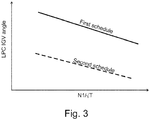
- Figure 3 shows a graph illustrating the first and second control schedules for the IGVs 32 in solid lines and dotted lines respectively.
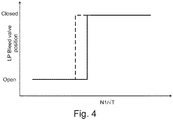
- a similar bleed valve 34 schedule is utilised.
- the bleed valves 34 are scheduled such that the bleed valves are open at low LPC 14 corrected speeds N1/ ⁇ T24, and closed at higher speeds, as shown.
- the threshold LPC 14 corrected speed N1/ ⁇ T24 at which the bleed valve is closed varies.
- the bleed valves 34 are operated in accordance with a first schedule (as shown by the solid line in figure 4 ), which has a threshold value such that the bleed valves 34 are opened at relatively high corrected speeds N1/ ⁇ T24.
- the bleed valves 32 are operated in accordance with a second schedule (as shown by the dotted line in figure 4 ), which has a threshold value such that the bleed valves 34 are opened at relatively low corrected speeds N1/ ⁇ T24.
- a second schedule as shown by the dotted line in figure 4
- IGV 32 vane angle decreases (i.e. the IGV opens) from a relatively closed position as low pressure compressor corrected speed N1/ ⁇ T24 increases. This ensures that the compressor is operated relatively efficiently, while ensuring that sufficient stall margin is maintained.
- the engine will be operated in accordance with the first schedule, as the LPC 14 and HPC 15 begin to accelerate. Consequently, at least initially, the LPC 14 is operated according to a relatively conservative compressor schedule.
- the IGV 32 vane angle again decreases (i.e. the IGV opens) as low pressure compressor corrected speed N1 ⁇ T24 increases.
- the second schedule has a lower IGV angle (i.e. a more open position) for a given LPC N1/ ⁇ T24 value.
- the slope i.e. the rate at which the IGVs open at increasing N1/ ⁇ T24
- the slope is the same or similar, with the graph shifted downwards between the first and second schedules.
- a constant IGV angle is subtracted from the first schedule to produce the second schedule.
- the slope may also vary between the first and second schedules. It will be understood that the schedules may not comprise a constant slope, but may comprise a complex curve.
- the LPC 14 is controlled in operation as follows. Starting from flight idle, both the LPC 14 and HPC 14 have relatively low rotational speeds N1, N2. As the engine accelerates, both compressors 14, 15 accelerate toward higher speeds. As the mass flow rate ⁇ through the HPC 15 is initially low, as indicated by the low pressure ratio P30:P26 across the HPC, the LPC 14 is operated in accordance with the first schedule. However, the HPC rapidly accelerates, thereby increasing the mass flow rate ⁇ and pressure ratio P30:P26 across the HPC. Consequently, the controller switches control of the IGVs to the second schedule, thereby reducing IGV vane angle, and increasing pressure ratio across the LPC 14, which in turn increases load on the LPC 14. Consequently, the engine is able to accelerate more quickly. Additionally, the increasing load on the LPC 14 in view of the reduced vane angle prevents excessive HPC 15 rotational speed increase, and so prevents HPC 15 runaway during acceleration.
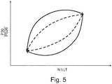
- the effect of the new method of operation on the high pressure compressor can be shown.
- the solid lines represent acceleration and deceleration of the engine from idle to maximum take-off thrust.
- the HPC compressor 15 ratio "overshoots", i.e. exceeds a desired maximum during acceleration, before reducing once more. This may cause surges or damage to the engine.
- the pressure ratio falls below a desired minimum during declaration, which may result in unstable combustion in the combustor and / or "flameout", i.e. shutdown of the engine.
- the control method of the current disclose shown in dotted lines results in a smooth acceleration of high pressure compressor pressure ratio as the engine accelerations, and also a smooth deceleration, with no overshoots.
- low and high pressure compressor 14 15 operational parameters (N1/ ⁇ T and P30:P26 respectively in this example) are again determined, in a similar manner to the first and second steps of the first embodiment. Again, alternative operational parameters as disclosed for the first embodiment could be utilised.
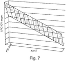
- an LPC 14 VGV 36 position is calculated according to a schedule that takes into account both LPC 14 rotational speed N1/ ⁇ T and HPC 15 compressor ratio P30:P26.
- IGV angle decreases on the basis of increased N1/ ⁇ T, similarly to the first and second schedules of the first embodiment.
- IGV angle also decreases as HPC 15 compressor ratio P30:P26 increases.
- a "correction factor" is applied to the schedule based on N1/ ⁇ T, with the IGV 36 vane angle reducing proportionate to P30:P26 increase. Consequently, finer control on the basis of HPC 15 mass flow ⁇ is achieved.
- bleed valve 34 opening threshold N1/ ⁇ T being determined on the basis of HPC 15 pressure ratio P30:P26, with higher pressure ratios generally leading to a lower bleed valve opening threshold N1/ ⁇ T.
- the bleed valve 34 is variable (i.e. has more than two positions)
- the extent of opening may be varied in relation to the HPC 15 pressure ratio, with higher ratios leading to a more closed position for a given N1/ ⁇ T.
- Such a method is particularly, though not exclusively, suitable for geared turbofans, where the LPC, low pressure turbine, reduction gearbox and fan are located on the same shaft.
Landscapes
- Engineering & Computer Science (AREA)
- Mechanical Engineering (AREA)
- General Engineering & Computer Science (AREA)
- Chemical & Material Sciences (AREA)
- Combustion & Propulsion (AREA)
- Physics & Mathematics (AREA)
- Fluid Mechanics (AREA)
- Life Sciences & Earth Sciences (AREA)
- Sustainable Development (AREA)
- Control Of Positive-Displacement Air Blowers (AREA)
- Structures Of Non-Positive Displacement Pumps (AREA)
Applications Claiming Priority (1)
| Application Number | Priority Date | Filing Date | Title |
|---|---|---|---|
| GBGB1803137.7A GB201803137D0 (en) | 2018-02-27 | 2018-02-27 | Gas turbine engine compressor management system |
Publications (2)
| Publication Number | Publication Date |
|---|---|
| EP3530929A1 true EP3530929A1 (fr) | 2019-08-28 |
| EP3530929B1 EP3530929B1 (fr) | 2021-12-08 |
Family
ID=61903224
Family Applications (1)
| Application Number | Title | Priority Date | Filing Date |
|---|---|---|---|
| EP19154176.2A Active EP3530929B1 (fr) | 2018-02-27 | 2019-01-29 | Système de gestion de compresseur de moteur de turbine à gaz |
Country Status (4)
| Country | Link |
|---|---|
| US (1) | US20190264701A1 (fr) |
| EP (1) | EP3530929B1 (fr) |
| CN (1) | CN110195659A (fr) |
| GB (1) | GB201803137D0 (fr) |
Families Citing this family (10)
| Publication number | Priority date | Publication date | Assignee | Title |
|---|---|---|---|---|
| US20190002117A1 (en) * | 2017-06-30 | 2019-01-03 | General Electric Company | Propulsion system for an aircraft |
| CN110735669B (zh) * | 2019-10-08 | 2021-12-28 | 中国航发沈阳发动机研究所 | 一种航空燃气涡轮发动机旋转失速判断方法及装置 |
| GB202000875D0 (en) * | 2019-11-29 | 2020-03-04 | Rolls Royce Plc | Flow machine performance modelling |
| BE1028232B1 (fr) * | 2020-04-23 | 2021-11-29 | Safran Aero Boosters | Méthode et système de contrôle d'un calage variable d'aubes d'un redresseur d'un compresseur basse pression d'une turbomachine d'aéronef |
| US11585279B2 (en) * | 2020-08-12 | 2023-02-21 | Pratt & Whitney Canada Corp. | Systems and methods for controlling a bleed-off valve of a gas turbine engine |
| US12196129B2 (en) | 2021-06-08 | 2025-01-14 | General Electric Company | Compressor with counter-rotating blade rows |
| US11739699B2 (en) | 2021-11-08 | 2023-08-29 | Pratt & Whitney Canada Corp. | Method of controlling the geometrical configuration of a variable geometry element in a gas turbine engine compressor stage |
| US12215590B2 (en) * | 2022-05-31 | 2025-02-04 | Pratt & Whitney Canada Corp. | Method for checking bleed-off valve closing point |
| GB202302422D0 (en) * | 2023-02-21 | 2023-04-05 | Rolls Royce Plc | Thrust control method for an airbreathing jet engine |
| US12129804B1 (en) * | 2023-09-01 | 2024-10-29 | Pratt & Whitney Canada Corp. | Shifted bleed valve modulation detection |
Citations (4)
| Publication number | Priority date | Publication date | Assignee | Title |
|---|---|---|---|---|
| EP2148044A2 (fr) * | 2008-07-23 | 2010-01-27 | Rolls-Royce plc | Agencement d'aube à stator variable de compresseur de moteur à turbine à gaz |
| EP2937522A1 (fr) * | 2014-04-25 | 2015-10-28 | Rolls-Royce plc | Commande de moteur de turbine à gaz |
| EP3141725A1 (fr) * | 2015-09-11 | 2017-03-15 | United Technologies Corporation | Système de commande et procédé de commande d'un moteur à turbine à gaz à section variable |
| GB2548584A (en) * | 2016-03-22 | 2017-09-27 | Robert Bodle Charles | Controlling gas turbine engines |
Family Cites Families (6)
| Publication number | Priority date | Publication date | Assignee | Title |
|---|---|---|---|---|
| US4928482A (en) * | 1988-09-20 | 1990-05-29 | United Technologies Corporation | Control of high compressor vanes and fuel for a gas turbine engine |
| JPH03504408A (ja) * | 1989-02-27 | 1991-09-26 | ユナイテッド・テクノロジーズ・コーポレイション | ガスタービンエンジンの制御装置 |
| US6735955B2 (en) * | 2001-10-10 | 2004-05-18 | Goodrich Pump & Engine Control Systems, Inc. | Control system for positioning compressor inlet guide vanes |
| US9097133B2 (en) * | 2012-06-04 | 2015-08-04 | United Technologies Corporation | Compressor tip clearance management for a gas turbine engine |
| WO2014185997A2 (fr) * | 2013-02-04 | 2014-11-20 | United Technologies Corporation | Vanne rotative pour voie d'écoulement de purge |
| US9777642B2 (en) * | 2014-11-21 | 2017-10-03 | General Electric Company | Gas turbine engine and method of assembling the same |
-
2018
- 2018-02-27 GB GBGB1803137.7A patent/GB201803137D0/en not_active Ceased
-
2019
- 2019-01-29 EP EP19154176.2A patent/EP3530929B1/fr active Active
- 2019-02-11 US US16/272,156 patent/US20190264701A1/en not_active Abandoned
- 2019-02-27 CN CN201910145942.1A patent/CN110195659A/zh active Pending
Patent Citations (4)
| Publication number | Priority date | Publication date | Assignee | Title |
|---|---|---|---|---|
| EP2148044A2 (fr) * | 2008-07-23 | 2010-01-27 | Rolls-Royce plc | Agencement d'aube à stator variable de compresseur de moteur à turbine à gaz |
| EP2937522A1 (fr) * | 2014-04-25 | 2015-10-28 | Rolls-Royce plc | Commande de moteur de turbine à gaz |
| EP3141725A1 (fr) * | 2015-09-11 | 2017-03-15 | United Technologies Corporation | Système de commande et procédé de commande d'un moteur à turbine à gaz à section variable |
| GB2548584A (en) * | 2016-03-22 | 2017-09-27 | Robert Bodle Charles | Controlling gas turbine engines |
Also Published As
| Publication number | Publication date |
|---|---|
| GB201803137D0 (en) | 2018-04-11 |
| CN110195659A (zh) | 2019-09-03 |
| EP3530929B1 (fr) | 2021-12-08 |
| US20190264701A1 (en) | 2019-08-29 |
Similar Documents
| Publication | Publication Date | Title |
|---|---|---|
| EP3530929B1 (fr) | Système de gestion de compresseur de moteur de turbine à gaz | |
| US3971208A (en) | Gas turbine fuel control | |
| US9003768B2 (en) | Variable fan inlet guide vane assembly, turbine engine with such an assembly and corresponding controlling method | |
| US5301500A (en) | Gas turbine engine for controlling stall margin | |
| US7762084B2 (en) | System and method for controlling the working line position in a gas turbine engine compressor | |
| JP5514354B2 (ja) | 流量調節ファンを備えたタービンエンジンとその動作方法 | |
| US9957832B2 (en) | Variable area turbine | |
| US11530650B2 (en) | Gas turbine engine with active variable turbine cooling | |
| US20180209350A1 (en) | Advanced Geared Gas Turbine Engine | |
| EP2798186A1 (fr) | Aube de guide d'entrée de ventilateur variable pour moteur à turbine | |
| US10859003B2 (en) | Control system for a gas turbine engine | |
| EP1788223A2 (fr) | Agencements de moteur à turbine et contrôle | |
| EP2809924B1 (fr) | Moteur à turbine à gaz avec tuyère de soufflante à section variable positionnée pour le démarrage | |
| US20230417190A1 (en) | Dual fuel pump system for an aircraft | |
| US11572805B2 (en) | System for supplying lubricant to a component | |
| EP4459117A2 (fr) | Procédé et système de régulation d'un moteur à faible puissance | |
| EP4144971B1 (fr) | Air de refroidissement refroidi avec décharge de pression sélective | |
| EP4151847A1 (fr) | Système et procédé de commande non basé sur un modèle utilisant un substitut de numéro de mach de sortie de turbine | |
| EP3835564A1 (fr) | Systèmes et procédés de fonctionnement d'un moteur ayant des mécanismes à géométrie variable | |
| CA3073692C (fr) | Systemes et methodes de controle d`un mecanisme a geometrie variable de moteur | |
| US20140137538A1 (en) | Fast Response Bypass Engine | |
| GB2589374A (en) | Electronic engine controller |
Legal Events
| Date | Code | Title | Description |
|---|---|---|---|
| PUAI | Public reference made under article 153(3) epc to a published international application that has entered the european phase |
Free format text: ORIGINAL CODE: 0009012 |
|
| STAA | Information on the status of an ep patent application or granted ep patent |
Free format text: STATUS: THE APPLICATION HAS BEEN PUBLISHED |
|
| AK | Designated contracting states |
Kind code of ref document: A1 Designated state(s): AL AT BE BG CH CY CZ DE DK EE ES FI FR GB GR HR HU IE IS IT LI LT LU LV MC MK MT NL NO PL PT RO RS SE SI SK SM TR |
|
| AX | Request for extension of the european patent |
Extension state: BA ME |
|
| STAA | Information on the status of an ep patent application or granted ep patent |
Free format text: STATUS: REQUEST FOR EXAMINATION WAS MADE |
|
| 17P | Request for examination filed |
Effective date: 20200120 |
|
| RAP1 | Party data changed (applicant data changed or rights of an application transferred) |
Owner name: ROLLS-ROYCE PLC |
|
| RBV | Designated contracting states (corrected) |
Designated state(s): AL AT BE BG CH CY CZ DE DK EE ES FI FR GB GR HR HU IE IS IT LI LT LU LV MC MK MT NL NO PL PT RO RS SE SI SK SM TR |
|
| STAA | Information on the status of an ep patent application or granted ep patent |
Free format text: STATUS: EXAMINATION IS IN PROGRESS |
|
| 17Q | First examination report despatched |
Effective date: 20201125 |
|
| GRAP | Despatch of communication of intention to grant a patent |
Free format text: ORIGINAL CODE: EPIDOSNIGR1 |
|
| STAA | Information on the status of an ep patent application or granted ep patent |
Free format text: STATUS: GRANT OF PATENT IS INTENDED |
|
| GRAS | Grant fee paid |
Free format text: ORIGINAL CODE: EPIDOSNIGR3 |
|
| INTG | Intention to grant announced |
Effective date: 20211008 |
|
| GRAA | (expected) grant |
Free format text: ORIGINAL CODE: 0009210 |
|
| STAA | Information on the status of an ep patent application or granted ep patent |
Free format text: STATUS: THE PATENT HAS BEEN GRANTED |
|
| AK | Designated contracting states |
Kind code of ref document: B1 Designated state(s): AL AT BE BG CH CY CZ DE DK EE ES FI FR GB GR HR HU IE IS IT LI LT LU LV MC MK MT NL NO PL PT RO RS SE SI SK SM TR |
|
| REG | Reference to a national code |
Ref country code: GB Ref legal event code: FG4D |
|
| REG | Reference to a national code |
Ref country code: AT Ref legal event code: REF Ref document number: 1453960 Country of ref document: AT Kind code of ref document: T Effective date: 20211215 Ref country code: CH Ref legal event code: EP |
|
| REG | Reference to a national code |
Ref country code: DE Ref legal event code: R096 Ref document number: 602019009796 Country of ref document: DE |
|
| REG | Reference to a national code |
Ref country code: IE Ref legal event code: FG4D |
|
| REG | Reference to a national code |
Ref country code: LT Ref legal event code: MG9D |
|
| REG | Reference to a national code |
Ref country code: NL Ref legal event code: MP Effective date: 20211208 |
|
| PG25 | Lapsed in a contracting state [announced via postgrant information from national office to epo] |
Ref country code: RS Free format text: LAPSE BECAUSE OF FAILURE TO SUBMIT A TRANSLATION OF THE DESCRIPTION OR TO PAY THE FEE WITHIN THE PRESCRIBED TIME-LIMIT Effective date: 20211208 Ref country code: LT Free format text: LAPSE BECAUSE OF FAILURE TO SUBMIT A TRANSLATION OF THE DESCRIPTION OR TO PAY THE FEE WITHIN THE PRESCRIBED TIME-LIMIT Effective date: 20211208 Ref country code: FI Free format text: LAPSE BECAUSE OF FAILURE TO SUBMIT A TRANSLATION OF THE DESCRIPTION OR TO PAY THE FEE WITHIN THE PRESCRIBED TIME-LIMIT Effective date: 20211208 Ref country code: BG Free format text: LAPSE BECAUSE OF FAILURE TO SUBMIT A TRANSLATION OF THE DESCRIPTION OR TO PAY THE FEE WITHIN THE PRESCRIBED TIME-LIMIT Effective date: 20220308 |
|
| REG | Reference to a national code |
Ref country code: AT Ref legal event code: MK05 Ref document number: 1453960 Country of ref document: AT Kind code of ref document: T Effective date: 20211208 |
|
| PG25 | Lapsed in a contracting state [announced via postgrant information from national office to epo] |
Ref country code: SE Free format text: LAPSE BECAUSE OF FAILURE TO SUBMIT A TRANSLATION OF THE DESCRIPTION OR TO PAY THE FEE WITHIN THE PRESCRIBED TIME-LIMIT Effective date: 20211208 Ref country code: NO Free format text: LAPSE BECAUSE OF FAILURE TO SUBMIT A TRANSLATION OF THE DESCRIPTION OR TO PAY THE FEE WITHIN THE PRESCRIBED TIME-LIMIT Effective date: 20220308 Ref country code: LV Free format text: LAPSE BECAUSE OF FAILURE TO SUBMIT A TRANSLATION OF THE DESCRIPTION OR TO PAY THE FEE WITHIN THE PRESCRIBED TIME-LIMIT Effective date: 20211208 Ref country code: HR Free format text: LAPSE BECAUSE OF FAILURE TO SUBMIT A TRANSLATION OF THE DESCRIPTION OR TO PAY THE FEE WITHIN THE PRESCRIBED TIME-LIMIT Effective date: 20211208 Ref country code: GR Free format text: LAPSE BECAUSE OF FAILURE TO SUBMIT A TRANSLATION OF THE DESCRIPTION OR TO PAY THE FEE WITHIN THE PRESCRIBED TIME-LIMIT Effective date: 20220309 Ref country code: ES Free format text: LAPSE BECAUSE OF FAILURE TO SUBMIT A TRANSLATION OF THE DESCRIPTION OR TO PAY THE FEE WITHIN THE PRESCRIBED TIME-LIMIT Effective date: 20211208 |
|
| PG25 | Lapsed in a contracting state [announced via postgrant information from national office to epo] |
Ref country code: NL Free format text: LAPSE BECAUSE OF FAILURE TO SUBMIT A TRANSLATION OF THE DESCRIPTION OR TO PAY THE FEE WITHIN THE PRESCRIBED TIME-LIMIT Effective date: 20211208 |
|
| PG25 | Lapsed in a contracting state [announced via postgrant information from national office to epo] |
Ref country code: SM Free format text: LAPSE BECAUSE OF FAILURE TO SUBMIT A TRANSLATION OF THE DESCRIPTION OR TO PAY THE FEE WITHIN THE PRESCRIBED TIME-LIMIT Effective date: 20211208 Ref country code: SK Free format text: LAPSE BECAUSE OF FAILURE TO SUBMIT A TRANSLATION OF THE DESCRIPTION OR TO PAY THE FEE WITHIN THE PRESCRIBED TIME-LIMIT Effective date: 20211208 Ref country code: RO Free format text: LAPSE BECAUSE OF FAILURE TO SUBMIT A TRANSLATION OF THE DESCRIPTION OR TO PAY THE FEE WITHIN THE PRESCRIBED TIME-LIMIT Effective date: 20211208 Ref country code: PT Free format text: LAPSE BECAUSE OF FAILURE TO SUBMIT A TRANSLATION OF THE DESCRIPTION OR TO PAY THE FEE WITHIN THE PRESCRIBED TIME-LIMIT Effective date: 20220408 Ref country code: EE Free format text: LAPSE BECAUSE OF FAILURE TO SUBMIT A TRANSLATION OF THE DESCRIPTION OR TO PAY THE FEE WITHIN THE PRESCRIBED TIME-LIMIT Effective date: 20211208 Ref country code: CZ Free format text: LAPSE BECAUSE OF FAILURE TO SUBMIT A TRANSLATION OF THE DESCRIPTION OR TO PAY THE FEE WITHIN THE PRESCRIBED TIME-LIMIT Effective date: 20211208 |
|
| PG25 | Lapsed in a contracting state [announced via postgrant information from national office to epo] |
Ref country code: PL Free format text: LAPSE BECAUSE OF FAILURE TO SUBMIT A TRANSLATION OF THE DESCRIPTION OR TO PAY THE FEE WITHIN THE PRESCRIBED TIME-LIMIT Effective date: 20211208 Ref country code: AT Free format text: LAPSE BECAUSE OF FAILURE TO SUBMIT A TRANSLATION OF THE DESCRIPTION OR TO PAY THE FEE WITHIN THE PRESCRIBED TIME-LIMIT Effective date: 20211208 |
|
| REG | Reference to a national code |
Ref country code: CH Ref legal event code: PL |
|
| REG | Reference to a national code |
Ref country code: DE Ref legal event code: R097 Ref document number: 602019009796 Country of ref document: DE |
|
| PG25 | Lapsed in a contracting state [announced via postgrant information from national office to epo] |
Ref country code: MC Free format text: LAPSE BECAUSE OF FAILURE TO SUBMIT A TRANSLATION OF THE DESCRIPTION OR TO PAY THE FEE WITHIN THE PRESCRIBED TIME-LIMIT Effective date: 20211208 Ref country code: IS Free format text: LAPSE BECAUSE OF FAILURE TO SUBMIT A TRANSLATION OF THE DESCRIPTION OR TO PAY THE FEE WITHIN THE PRESCRIBED TIME-LIMIT Effective date: 20220408 |
|
| REG | Reference to a national code |
Ref country code: BE Ref legal event code: MM Effective date: 20220131 |
|
| PLBE | No opposition filed within time limit |
Free format text: ORIGINAL CODE: 0009261 |
|
| STAA | Information on the status of an ep patent application or granted ep patent |
Free format text: STATUS: NO OPPOSITION FILED WITHIN TIME LIMIT |
|
| PG25 | Lapsed in a contracting state [announced via postgrant information from national office to epo] |
Ref country code: LU Free format text: LAPSE BECAUSE OF NON-PAYMENT OF DUE FEES Effective date: 20220129 Ref country code: DK Free format text: LAPSE BECAUSE OF FAILURE TO SUBMIT A TRANSLATION OF THE DESCRIPTION OR TO PAY THE FEE WITHIN THE PRESCRIBED TIME-LIMIT Effective date: 20211208 Ref country code: AL Free format text: LAPSE BECAUSE OF FAILURE TO SUBMIT A TRANSLATION OF THE DESCRIPTION OR TO PAY THE FEE WITHIN THE PRESCRIBED TIME-LIMIT Effective date: 20211208 |
|
| 26N | No opposition filed |
Effective date: 20220909 |
|
| PG25 | Lapsed in a contracting state [announced via postgrant information from national office to epo] |
Ref country code: SI Free format text: LAPSE BECAUSE OF FAILURE TO SUBMIT A TRANSLATION OF THE DESCRIPTION OR TO PAY THE FEE WITHIN THE PRESCRIBED TIME-LIMIT Effective date: 20211208 Ref country code: BE Free format text: LAPSE BECAUSE OF NON-PAYMENT OF DUE FEES Effective date: 20220131 |
|
| PG25 | Lapsed in a contracting state [announced via postgrant information from national office to epo] |
Ref country code: LI Free format text: LAPSE BECAUSE OF NON-PAYMENT OF DUE FEES Effective date: 20220131 Ref country code: CH Free format text: LAPSE BECAUSE OF NON-PAYMENT OF DUE FEES Effective date: 20220131 |
|
| PG25 | Lapsed in a contracting state [announced via postgrant information from national office to epo] |
Ref country code: IE Free format text: LAPSE BECAUSE OF NON-PAYMENT OF DUE FEES Effective date: 20220129 |
|
| PG25 | Lapsed in a contracting state [announced via postgrant information from national office to epo] |
Ref country code: IT Free format text: LAPSE BECAUSE OF FAILURE TO SUBMIT A TRANSLATION OF THE DESCRIPTION OR TO PAY THE FEE WITHIN THE PRESCRIBED TIME-LIMIT Effective date: 20211208 |
|
| P01 | Opt-out of the competence of the unified patent court (upc) registered |
Effective date: 20230528 |
|
| PG25 | Lapsed in a contracting state [announced via postgrant information from national office to epo] |
Ref country code: MK Free format text: LAPSE BECAUSE OF FAILURE TO SUBMIT A TRANSLATION OF THE DESCRIPTION OR TO PAY THE FEE WITHIN THE PRESCRIBED TIME-LIMIT Effective date: 20211208 Ref country code: CY Free format text: LAPSE BECAUSE OF FAILURE TO SUBMIT A TRANSLATION OF THE DESCRIPTION OR TO PAY THE FEE WITHIN THE PRESCRIBED TIME-LIMIT Effective date: 20211208 |
|
| PG25 | Lapsed in a contracting state [announced via postgrant information from national office to epo] |
Ref country code: HU Free format text: LAPSE BECAUSE OF FAILURE TO SUBMIT A TRANSLATION OF THE DESCRIPTION OR TO PAY THE FEE WITHIN THE PRESCRIBED TIME-LIMIT; INVALID AB INITIO Effective date: 20190129 |
|
| PG25 | Lapsed in a contracting state [announced via postgrant information from national office to epo] |
Ref country code: TR Free format text: LAPSE BECAUSE OF FAILURE TO SUBMIT A TRANSLATION OF THE DESCRIPTION OR TO PAY THE FEE WITHIN THE PRESCRIBED TIME-LIMIT Effective date: 20211208 |
|
| PG25 | Lapsed in a contracting state [announced via postgrant information from national office to epo] |
Ref country code: MT Free format text: LAPSE BECAUSE OF FAILURE TO SUBMIT A TRANSLATION OF THE DESCRIPTION OR TO PAY THE FEE WITHIN THE PRESCRIBED TIME-LIMIT Effective date: 20211208 |
|
| PGFP | Annual fee paid to national office [announced via postgrant information from national office to epo] |
Ref country code: GB Payment date: 20260126 Year of fee payment: 8 |
|
| PGFP | Annual fee paid to national office [announced via postgrant information from national office to epo] |
Ref country code: DE Payment date: 20260127 Year of fee payment: 8 |
|
| PGFP | Annual fee paid to national office [announced via postgrant information from national office to epo] |
Ref country code: FR Payment date: 20260126 Year of fee payment: 8 |