EP3530963B1 - Dispositif de connexion pour sommiers a lattes - Google Patents
Dispositif de connexion pour sommiers a lattes Download PDFInfo
- Publication number
- EP3530963B1 EP3530963B1 EP19158430.9A EP19158430A EP3530963B1 EP 3530963 B1 EP3530963 B1 EP 3530963B1 EP 19158430 A EP19158430 A EP 19158430A EP 3530963 B1 EP3530963 B1 EP 3530963B1
- Authority
- EP
- European Patent Office
- Prior art keywords
- longitudinal
- slatted frame
- parts
- locking element
- longitudinal spar
- Prior art date
- Legal status (The legal status is an assumption and is not a legal conclusion. Google has not performed a legal analysis and makes no representation as to the accuracy of the status listed.)
- Active
Links
Images

Classifications
-
- F—MECHANICAL ENGINEERING; LIGHTING; HEATING; WEAPONS; BLASTING
- F16—ENGINEERING ELEMENTS AND UNITS; GENERAL MEASURES FOR PRODUCING AND MAINTAINING EFFECTIVE FUNCTIONING OF MACHINES OR INSTALLATIONS; THERMAL INSULATION IN GENERAL
- F16B—DEVICES FOR FASTENING OR SECURING CONSTRUCTIONAL ELEMENTS OR MACHINE PARTS TOGETHER, e.g. NAILS, BOLTS, CIRCLIPS, CLAMPS, CLIPS OR WEDGES; JOINTS OR JOINTING
- F16B5/00—Joining sheets or plates, e.g. panels, to one another or to strips or bars parallel to them
- F16B5/12—Fastening strips or bars to sheets or plates, e.g. rubber strips, decorative strips for motor vehicles, by means of clips
- F16B5/121—Fastening strips or bars to sheets or plates, e.g. rubber strips, decorative strips for motor vehicles, by means of clips fastened over the edge(s) of the sheet(s) or plate(s)
-
- A—HUMAN NECESSITIES
- A47—FURNITURE; DOMESTIC ARTICLES OR APPLIANCES; COFFEE MILLS; SPICE MILLS; SUCTION CLEANERS IN GENERAL
- A47C—CHAIRS; SOFAS; BEDS
- A47C19/00—Bedsteads
- A47C19/04—Extensible bedsteads, e.g. with adjustment of length, width, height
-
- F—MECHANICAL ENGINEERING; LIGHTING; HEATING; WEAPONS; BLASTING
- F16—ENGINEERING ELEMENTS AND UNITS; GENERAL MEASURES FOR PRODUCING AND MAINTAINING EFFECTIVE FUNCTIONING OF MACHINES OR INSTALLATIONS; THERMAL INSULATION IN GENERAL
- F16B—DEVICES FOR FASTENING OR SECURING CONSTRUCTIONAL ELEMENTS OR MACHINE PARTS TOGETHER, e.g. NAILS, BOLTS, CIRCLIPS, CLAMPS, CLIPS OR WEDGES; JOINTS OR JOINTING
- F16B2/00—Friction-grip releasable fastenings
- F16B2/20—Clips, i.e. with gripping action effected solely by the inherent resistance to deformation of the material of the fastening
- F16B2/22—Clips, i.e. with gripping action effected solely by the inherent resistance to deformation of the material of the fastening of resilient material, e.g. rubbery material
-
- F—MECHANICAL ENGINEERING; LIGHTING; HEATING; WEAPONS; BLASTING
- F16—ENGINEERING ELEMENTS AND UNITS; GENERAL MEASURES FOR PRODUCING AND MAINTAINING EFFECTIVE FUNCTIONING OF MACHINES OR INSTALLATIONS; THERMAL INSULATION IN GENERAL
- F16B—DEVICES FOR FASTENING OR SECURING CONSTRUCTIONAL ELEMENTS OR MACHINE PARTS TOGETHER, e.g. NAILS, BOLTS, CIRCLIPS, CLAMPS, CLIPS OR WEDGES; JOINTS OR JOINTING
- F16B5/00—Joining sheets or plates, e.g. panels, to one another or to strips or bars parallel to them
- F16B5/12—Fastening strips or bars to sheets or plates, e.g. rubber strips, decorative strips for motor vehicles, by means of clips
- F16B5/123—Auxiliary fasteners specially designed for this purpose
Definitions
- the invention relates to a slatted frame connecting device for connecting a first and a second longitudinal beam part of a slatted frame longitudinal beam at a connection point.
- the invention further relates to the use of a slatted frame connecting device on a slatted frame with at least two longitudinal beam parts.
- the longitudinal bars of a slatted frame such as that used in particular for beds, divisible.
- the longitudinal bars of the slatted frame are divided into at least two longitudinal bar parts, which then have to be connected at a connection point to assemble the finished slatted frame.
- the longitudinal slatted frame beam Only when the longitudinal beam parts are joined together does the longitudinal slatted frame beam, which usually extends over the entire length of the slatted frame, come into being.
- parts or sections of the slatted frame are created that are easier to move and also easier to transport.
- Such slatted frame parts can be loaded onto standard pallets and shipped and stored using them.
- a connector for hollow profiles which comprises two half-shells, each with an end region of two towards each other connecting hollow profiles are to be introduced.
- Each half-shell has at least two cams on its surface facing the hollow profile, each of which is designed to snap into an associated recess on the inner surface of the hollow profile.
- a compression spring is arranged between the two half-shells at one of their axial end regions, which presses the two half-shells apart there.
- a wedge lock ring is provided, into which a fastening wedge is to be inserted.
- the two hollow profiles are pushed over the half-shells at their hollow profile ends.
- the fastening wedge is then driven, with the outer surfaces of the two half-shells leaning against the inner surfaces of the two hollow profile ends.
- a butt connector for scaffolding tubes or poles which comprises two mutually identical connecting parts with seats adapted to the surrounding surface of the abutting tubes or poles and projections attached to them, which engage in matching recesses in the tubes or poles. Both connecting parts must be pressed firmly onto the pipes or rods using a few screw bolts and nuts.
- a corner connection structure of an aluminum extrusion cabinet with a corner connector is known.
- the corner connector is used to connect hollow rods arranged at right angles to each other.
- a through hole is provided on the corner connector through which a screw can be inserted.
- a slatted frame connecting device for connecting a first and a second longitudinal spar part of a slatted frame longitudinal spar at a connection point according to claim 1, in which a longitudinal element bridging the connection point is provided, on which at least one in the first longitudinal spar -The first cross piece to be engaged and at least one second cross piece to be engaged in the second longitudinal spar part protrude, and a locking element is provided with which the cross pieces can be prevented from emerging from the associated longitudinal spar part.
- the invention is directed to the use of such a slatted frame connecting device according to the invention on a slatted frame with at least two longitudinal beam parts.
- a simple, very functional and at the same time very stable connection of longitudinal spar parts of a slatted frame is created.
- the assembly or assembly as well as the disassembly or disassembly of the slatted frame according to the invention is possible completely without tools.
- This is achieved in that the two functions of stably connecting the longitudinal spar parts and securing this connection are designed or implemented separately in separate elements.
- An element here is understood to mean a component, in particular a separate component, which specifically develops a functional effect.
- the first component is a longitudinal element, which, due to its longitudinal stretch, creates a bridge-like connection between the two the longitudinal spar parts involved.
- a locking element is provided as a second component, which forms a security or lock for the longitudinal element.
- the locking element therefore holds the longitudinal element in its active position and thus ensures that this longitudinal element remains stationary in this position and acts as the actual connector of the longitudinal spar parts over the service life of the slatted frame.
- the cross pieces formed on the longitudinal element establish the coupling to one of the longitudinal spar parts. These cross pieces extend transversely to the longitudinal extent of the longitudinal element and thereby act as a bolt or mandrel that protrudes into the associated longitudinal spar part.
- the cross pieces create a positive and therefore particularly resilient connection to the longitudinal beam part. At the same time, such a coupling is particularly easy to produce by simply pushing the cross pieces laterally into the associated longitudinal spar part. The entire connection can then also be secured permanently in a very simple manner by clipping on the locking element as explained.
- two first cross pieces and two second cross pieces are provided on the longitudinal element.
- a statically clearly defined coupling is created on the associated longitudinal spar part, which as such can also be produced and released individually.
- the longitudinal spar parts can also be individually attached to and detached from the connecting device according to the invention.
- the connecting device can thus be particularly advantageously initially arranged on only one longitudinal spar part and only then can the second longitudinal spar part be assembled into this grouping. Only then does the locking element according to the invention need to be attached in order to do so To permanently secure the entire arrangement. The entire arrangement can be dismantled in an equally simple manner in the reverse order.
- a further cross piece to be engaged at the connection point is also preferably provided on the longitudinal element.
- This cross piece which engages at the connection point itself, a defined distance between the longitudinal beam parts can be set.
- a coupling to both longitudinal spar parts involved can be created with just one cross piece.
- a connection to two longitudinal spar parts can be created with just three cross pieces. This is particularly advantageous because corresponding openings, in particular bores, have to be formed on the longitudinal spar parts in order to introduce the cross pieces. This molding requires separate work steps that should be saved as much as possible.
- the longitudinal element is preferably made of metal, in particular steel.
- the longitudinal spar parts themselves are usually made of wood. But they can also be made of metal, especially aluminum, or plastic.
- a simple, cost-effective and at the same time statically high-quality coupling is always possible using the cross pieces mentioned.
- the cross pieces preferably also have a circular cross-sectional area and are therefore preferably designed as round bolts. Alternatively, the cross pieces preferably have a square or rectangular cross-sectional area.
- the locking element is preferably designed with a bolt piece to engage in at least one of the longitudinal spar parts.
- This bolt piece couples the locking element to one or both longitudinal spar parts and thus positions it.
- the locking element becomes stationary with the bolt piece held so that the longitudinal element can be secure in terms of its position.
- the locking element is further designed with a clamp piece with a locking lug which extends over the longitudinal element.
- the clamp piece acts as a clip that can simply be placed manually on the longitudinal element when installing the locking element. The clip thus engages over the longitudinal element transversely to the direction of the cross pieces and thereby prevents one of the cross pieces from migrating out of the associated longitudinal spar part in its axial direction.
- the locking element is also advantageously designed with a spacer located at the connection point between the longitudinal spar parts.
- the spacer serves as an intermediate layer or intermediate layer between the end faces of the two longitudinal spar parts involved, by means of which noise and abrasion between these end faces of the longitudinal spar parts can be avoided.
- the spacer is advantageously also formed by the said bolt piece.
- the locking element is made of plastic in a particularly cost-effective and functionally advantageous manner.
- the plastic used preferably has a material composition such that a certain elasticity and breaking strength is guaranteed.
- connection point between the two longitudinal spar parts can be advantageously designed in various ways with regard to their shape.
- a shape is preferred in which the end faces of the longitudinal spar parts interlock with one another in the form of a tongue-and-groove connection with or without an undercut.
- a shape is preferred in which the end faces of the longitudinal spar parts have a rounded or S-shaped shape. With such shapes is a Pre-positioning of the longitudinal spar parts relative to each other before assembly is possible.
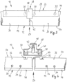
- a slatted frame connecting device 10 is shown, which is intended for producing a continuous slatted frame longitudinal beam 12.
- the slatted frame longitudinal spar 12 is designed from a first longitudinal spar part 14 and a second longitudinal spar part 16, each of which extends in a longitudinal direction 18 as strips or spars with a rectangular cross-sectional area.
- the first longitudinal spar part 14 ends at a first end face 20 and the second longitudinal spar part 16 ends at an end face 20 opposite this end face End face 22.
- a connection point 24 is formed between the end faces 20 and 22, at which the two longitudinal spar parts 14 and 16 lie opposite one another at a slight distance.
- the slatted frame connecting device 10 is designed with a longitudinal element 26, which is made of metal, in this case steel, and includes a plate piece 28 and four cross pieces 30.
- the plate piece 28 is designed as a strip or flat iron with a rectangular cross-sectional area and extends in the longitudinal direction 18 from the first longitudinal spar part 14 over the connection point 24 to over the second longitudinal spar part 16.
- the cross pieces 30 each protrude from the plate piece 28 in a transverse direction 32, which extends transversely to the longitudinal direction 18. Two of the four cross pieces 30 are located on that side of the longitudinal element 26 that covers the first longitudinal spar part 14. The other two of the four cross pieces 30 are located on the other side of the longitudinal element 26, i.e. where it covers the second longitudinal spar part 16.
- the cross pieces 30 each have a certain distance in the longitudinal direction 18 and grip when assembled (see Fig. 2 ) in transverse openings 34, which are formed on the longitudinal spar parts 14 and 16, respectively.
- the transverse openings 34 also extend in the transverse direction 32 in such a way that the longitudinal element 26 stationarily couples the longitudinal spar parts 14 and 16, which are opposite on their end faces 20 and 22, to one another in the longitudinal direction 18.
- transverse openings 34 are designed as blind holes at appropriate distances in side surfaces 36 of the longitudinal spar parts 14 and 16 and are designed to be just as large in terms of their cross-sectional area as the cross pieces 30.
- a locking element 38 made of plastic is provided in the slatted frame connecting device 10, which includes a plate-shaped head piece 40 with a circular cylindrical bolt piece 42 projecting at right angles therefrom.
- the bolt piece 42 is to be inserted into a bolt opening 44, which is formed in the area of the connection point 24 in the form of two cylindrical shells on the two end faces 20 and 22.
- the bolt opening 44 protrudes in the embodiment according to Fig. 1 to 3 from an underside 46 of the two longitudinal spar parts 14 and 16 into this.
- the bolt opening 44 also extends transversely to the longitudinal direction 18, but offset at an angle of 90 ° to the transverse direction 32 of the cross pieces 30.
- the locking element 38 also has a clamp piece 48 which projects laterally from the head piece 40 and which, when the bolt piece 42 is inserted, engages over the plate piece 28 of the longitudinal element 26 (see Fig. 3 ).
- clamp piece 48 When assembled, the clamp piece 48 prevents the longitudinal element 26 and its cross pieces 30 from migrating out of the transverse openings 34.
- the associated locking element 38 is also equipped with a bolt piece 42.
- the ring openings 52 are located on an upper side 54 of the longitudinal spar parts 14 and 16 and there establish a pressure-loaded connection between the longitudinal spar parts 14 and 16.
- the bolt piece 42 of the locking element 38 securely maintains a distance between the end faces 20 and 22. In particular, frictional noises between the end faces 20 and 22 can be avoided.
- a tensile-bending connection between the longitudinal spar parts 14 and 16 is also possible, as in the embodiment Fig. 1 to 3 , created by means of the longitudinal element 26 and its cross pieces 30 in the transverse openings 34. These cross pieces 30, together with the elongated plate piece 28, are again located near the underside 46 of the longitudinal spar parts 14 and 16.
Landscapes
- Engineering & Computer Science (AREA)
- General Engineering & Computer Science (AREA)
- Mechanical Engineering (AREA)
- Mutual Connection Of Rods And Tubes (AREA)
Claims (8)
- Dispositif de connexion pour sommier à lattes (10) servant à connecter une première et une deuxième partie de longeron (14, 16) d'un longeron de sommier à lattes (12) au niveau d'un point de jonction (24) ;dans lequel un élément longitudinal (26) servant au pontage du point de jonction (24) est prévu, au niveau duquel ressortent au moins une première pièce transversale (30) à imbriquer dans la première partie de longeron (14) et au moins une deuxième pièce transversale (30), à imbriquer dans la deuxième partie de longeron (16) et un élément de blocage (38) étant prévu à l'aide duquel une sortie des pièces transversales (30) peut être empêchée hors de la partie de longeron (14, 16) associée ;dans lequel l'élément de blocage (38) avec une pièce en pince pouvant imbriquer l'élément longitudinal (26) (48) est réalisé avec un bec d'arrêt, dans lequel la pièce en pince agit comme un clips pouvant être mis en place sur l'élément longitudinal (26) lors du montage de l'élément de blocage (38) et englobant ainsi l'élément longitudinal (26) avec le clips, transversalement à la direction des pièces transversales.
- Dispositif de connexion pour sommier à lattes selon la revendication 1, caractérisé en ce que deux premières pièces transversales (30) et deux deuxièmes pièces transversales (30) sont prévues au niveau de l'élément longitudinal (26).
- Dispositif de connexion pour sommier à lattes selon la revendication 1 ou 2, caractérisé en ce qu'une pièce transversale supplémentaire s'imbriquant au niveau du point de jonction (24) est prévue au niveau de l'élément longitudinal (26).
- Dispositif de connexion pour sommier à lattes selon l'une quelconque des revendications 1 à 3, caractérisé en ce que l'élément longitudinal (26) est fabriqué en métal, notamment en acier.
- Dispositif de connexion pour sommier à lattes selon l'une quelconque des revendications 1 à 4, caractérisé en ce que l'élément de blocage (38) est réalisé avec une pièce de boulon (42) s'imbriquant dans au moins une des parties de longeron (14, 16).
- Dispositif de connexion pour sommier à lattes selon l'une quelconque des revendications 1 à 5, caractérisé en ce que l'élément de blocage (38) est réalisé avec une pièce d'écartement reposant entre les parties de longeron (14, 16), au niveau du point de jonction (24).
- Dispositif de connexion pour sommier à lattes selon l'une quelconque des revendications 1 à 6, caractérisé en ce que l'élément de blocage (38) est fabriqué en matière plastique.
- Utilisation d'un dispositif de connexion pour sommier à lattes (10) selon l'une quelconque des revendications 1 à 7 au niveau d'un sommier à lattes doté d'au moins deux parties de longeron (14, 16).
Applications Claiming Priority (1)
| Application Number | Priority Date | Filing Date | Title |
|---|---|---|---|
| DE102018103948.4A DE102018103948A1 (de) | 2018-02-21 | 2018-02-21 | Lattenrost-verbindungseinrichtung |
Publications (3)
| Publication Number | Publication Date |
|---|---|
| EP3530963A1 EP3530963A1 (fr) | 2019-08-28 |
| EP3530963B1 true EP3530963B1 (fr) | 2023-10-04 |
| EP3530963C0 EP3530963C0 (fr) | 2023-10-04 |
Family
ID=65520088
Family Applications (1)
| Application Number | Title | Priority Date | Filing Date |
|---|---|---|---|
| EP19158430.9A Active EP3530963B1 (fr) | 2018-02-21 | 2019-02-21 | Dispositif de connexion pour sommiers a lattes |
Country Status (2)
| Country | Link |
|---|---|
| EP (1) | EP3530963B1 (fr) |
| DE (1) | DE102018103948A1 (fr) |
Citations (1)
| Publication number | Priority date | Publication date | Assignee | Title |
|---|---|---|---|---|
| US6415465B1 (en) * | 2000-02-02 | 2002-07-09 | Lawrence M. Harrow | Bed frame with unique connector and method |
Family Cites Families (9)
| Publication number | Priority date | Publication date | Assignee | Title |
|---|---|---|---|---|
| DE7523178U (de) * | 1975-12-18 | Franke & Co Kg | Bettbeschlag | |
| DE815096C (de) * | 1950-03-31 | 1951-09-27 | Dalmine Spa | Stossverbinder fuer Geruestrohre oder -stangen |
| DE2103504C3 (de) * | 1971-01-15 | 1974-06-20 | Mannesmann Leichtbau Gmbh, 8000 Muenchen | Verbinder für Profilrohre |
| US3871039A (en) * | 1974-05-09 | 1975-03-18 | Lear Siegler Inc | Bed frame |
| US4135266A (en) * | 1977-04-06 | 1979-01-23 | Lear Siegler, Inc. | Adjustable bed frame |
| DE29615173U1 (de) * | 1996-08-31 | 1996-11-07 | S. Döscher Handels KG Gerätebau, 27572 Bremerhaven | Bett, insbesondere Pflegebett für die Haus- und/oder Heimpflege |
| DE202004014352U1 (de) * | 2004-09-13 | 2004-11-11 | C & M Beteiligung Gmbh | Bettgestell |
| CN2798729Y (zh) * | 2005-06-21 | 2006-07-26 | 长城国际床业有限公司 | 改进的床架的固定结构 |
| US20110241502A1 (en) * | 2010-04-02 | 2011-10-06 | Pao-Yi Kao | Corner joint coupling structure of aluminum extrusion cabinet |
-
2018
- 2018-02-21 DE DE102018103948.4A patent/DE102018103948A1/de not_active Withdrawn
-
2019
- 2019-02-21 EP EP19158430.9A patent/EP3530963B1/fr active Active
Patent Citations (1)
| Publication number | Priority date | Publication date | Assignee | Title |
|---|---|---|---|---|
| US6415465B1 (en) * | 2000-02-02 | 2002-07-09 | Lawrence M. Harrow | Bed frame with unique connector and method |
Also Published As
| Publication number | Publication date |
|---|---|
| DE102018103948A1 (de) | 2019-08-22 |
| EP3530963C0 (fr) | 2023-10-04 |
| EP3530963A1 (fr) | 2019-08-28 |
Similar Documents
| Publication | Publication Date | Title |
|---|---|---|
| DE3320684C2 (de) | Zusammenbaugestell | |
| DE202013105584U1 (de) | Lager für eine Unterkonstruktion, beispielsweise einer Terrasse | |
| EP3124734B1 (fr) | Systeme de liaison destine a relier un jambage a un profil de cadre d'une fenetre ou d'une porte en matiere plastique | |
| EP2636830B1 (fr) | Fixation de penture, ensemble avec fixation de penture et penture ainsi qu'agencement de porte | |
| AT408773B (de) | Sieb und verfahren zur herstellung eines derartigen siebes | |
| EP4047220B1 (fr) | Unité de montage pourvue d'au moins un rail de montage et d'au moins une pince de retenue | |
| EP2128366B1 (fr) | Armature pour porte coulissante | |
| EP1213490A1 (fr) | Moyen de connection pour barres profilées | |
| EP3530963B1 (fr) | Dispositif de connexion pour sommiers a lattes | |
| WO2012123116A1 (fr) | Module à assembler ainsi que dispositif de suspension pour rails de support et leurs procédés de fabrication. | |
| EP2754803B1 (fr) | Crémone de fenêtre ou de porte et tringle pour une telle crémone | |
| DE202013103254U1 (de) | Verbindung zwischen Profilelementen einer Rahmenkonstruktion | |
| EP4223180B1 (fr) | Système de rayonnage | |
| EP3574163B1 (fr) | Set et structure de cadre pour une estrade, une scène et/ou une tribune | |
| EP0576429A1 (fr) | Metre pliant en bois. | |
| DE2300532C2 (de) | Wärmeisolierendes Verbundprofil für Fensterrahmen, Türrahmen od.dgl | |
| DE20107168U1 (de) | T-Verbindung zweier Profilstäbe | |
| EP2354432B1 (fr) | Vantail d'une porte coulissante | |
| DE202017003846U1 (de) | Verschiedene Materialien aufweisende, rastende Profilschiene | |
| EP3870864B1 (fr) | Ensemble de raccordement | |
| EP3992474B1 (fr) | Ensemble d'au moins deux profilés tubulaires ronds reliés de manière angulaire | |
| WO2000006862A1 (fr) | Garniture de bielles motrices avec renvoi d'angle | |
| EP2017483A2 (fr) | Structure de profilé | |
| EP3296486A1 (fr) | Ferrure d'assemblage pour l'assemblage d'éléments allongés de recouvrement | |
| EP1950361A1 (fr) | Plinthe pour un échafaudage et son procédé de fabrication |
Legal Events
| Date | Code | Title | Description |
|---|---|---|---|
| PUAI | Public reference made under article 153(3) epc to a published international application that has entered the european phase |
Free format text: ORIGINAL CODE: 0009012 |
|
| STAA | Information on the status of an ep patent application or granted ep patent |
Free format text: STATUS: THE APPLICATION HAS BEEN PUBLISHED |
|
| AK | Designated contracting states |
Kind code of ref document: A1 Designated state(s): AL AT BE BG CH CY CZ DE DK EE ES FI FR GB GR HR HU IE IS IT LI LT LU LV MC MK MT NL NO PL PT RO RS SE SI SK SM TR |
|
| AX | Request for extension of the european patent |
Extension state: BA ME |
|
| STAA | Information on the status of an ep patent application or granted ep patent |
Free format text: STATUS: REQUEST FOR EXAMINATION WAS MADE |
|
| 17P | Request for examination filed |
Effective date: 20200227 |
|
| RBV | Designated contracting states (corrected) |
Designated state(s): AL AT BE BG CH CY CZ DE DK EE ES FI FR GB GR HR HU IE IS IT LI LT LU LV MC MK MT NL NO PL PT RO RS SE SI SK SM TR |
|
| STAA | Information on the status of an ep patent application or granted ep patent |
Free format text: STATUS: EXAMINATION IS IN PROGRESS |
|
| 17Q | First examination report despatched |
Effective date: 20200506 |
|
| GRAP | Despatch of communication of intention to grant a patent |
Free format text: ORIGINAL CODE: EPIDOSNIGR1 |
|
| STAA | Information on the status of an ep patent application or granted ep patent |
Free format text: STATUS: GRANT OF PATENT IS INTENDED |
|
| INTG | Intention to grant announced |
Effective date: 20230531 |
|
| GRAS | Grant fee paid |
Free format text: ORIGINAL CODE: EPIDOSNIGR3 |
|
| GRAA | (expected) grant |
Free format text: ORIGINAL CODE: 0009210 |
|
| STAA | Information on the status of an ep patent application or granted ep patent |
Free format text: STATUS: THE PATENT HAS BEEN GRANTED |
|
| AK | Designated contracting states |
Kind code of ref document: B1 Designated state(s): AL AT BE BG CH CY CZ DE DK EE ES FI FR GB GR HR HU IE IS IT LI LT LU LV MC MK MT NL NO PL PT RO RS SE SI SK SM TR |
|
| REG | Reference to a national code |
Ref country code: GB Ref legal event code: FG4D Free format text: NOT ENGLISH |
|
| REG | Reference to a national code |
Ref country code: CH Ref legal event code: EP |
|
| REG | Reference to a national code |
Ref country code: DE Ref legal event code: R096 Ref document number: 502019009528 Country of ref document: DE |
|
| REG | Reference to a national code |
Ref country code: IE Ref legal event code: FG4D Free format text: LANGUAGE OF EP DOCUMENT: GERMAN |
|
| U01 | Request for unitary effect filed |
Effective date: 20231103 |
|
| U07 | Unitary effect registered |
Designated state(s): AT BE BG DE DK EE FI FR IT LT LU LV MT NL PT SE SI Effective date: 20231121 |
|
| U20 | Renewal fee for the european patent with unitary effect paid |
Year of fee payment: 6 Effective date: 20240215 |
|
| PG25 | Lapsed in a contracting state [announced via postgrant information from national office to epo] |
Ref country code: GR Free format text: LAPSE BECAUSE OF FAILURE TO SUBMIT A TRANSLATION OF THE DESCRIPTION OR TO PAY THE FEE WITHIN THE PRESCRIBED TIME-LIMIT Effective date: 20240105 |
|
| PG25 | Lapsed in a contracting state [announced via postgrant information from national office to epo] |
Ref country code: IS Free format text: LAPSE BECAUSE OF FAILURE TO SUBMIT A TRANSLATION OF THE DESCRIPTION OR TO PAY THE FEE WITHIN THE PRESCRIBED TIME-LIMIT Effective date: 20240204 |
|
| PG25 | Lapsed in a contracting state [announced via postgrant information from national office to epo] |
Ref country code: ES Free format text: LAPSE BECAUSE OF FAILURE TO SUBMIT A TRANSLATION OF THE DESCRIPTION OR TO PAY THE FEE WITHIN THE PRESCRIBED TIME-LIMIT Effective date: 20231004 |
|
| PG25 | Lapsed in a contracting state [announced via postgrant information from national office to epo] |
Ref country code: IS Free format text: LAPSE BECAUSE OF FAILURE TO SUBMIT A TRANSLATION OF THE DESCRIPTION OR TO PAY THE FEE WITHIN THE PRESCRIBED TIME-LIMIT Effective date: 20240204 Ref country code: GR Free format text: LAPSE BECAUSE OF FAILURE TO SUBMIT A TRANSLATION OF THE DESCRIPTION OR TO PAY THE FEE WITHIN THE PRESCRIBED TIME-LIMIT Effective date: 20240105 Ref country code: ES Free format text: LAPSE BECAUSE OF FAILURE TO SUBMIT A TRANSLATION OF THE DESCRIPTION OR TO PAY THE FEE WITHIN THE PRESCRIBED TIME-LIMIT Effective date: 20231004 |
|
| PG25 | Lapsed in a contracting state [announced via postgrant information from national office to epo] |
Ref country code: RS Free format text: LAPSE BECAUSE OF FAILURE TO SUBMIT A TRANSLATION OF THE DESCRIPTION OR TO PAY THE FEE WITHIN THE PRESCRIBED TIME-LIMIT Effective date: 20231004 Ref country code: PL Free format text: LAPSE BECAUSE OF FAILURE TO SUBMIT A TRANSLATION OF THE DESCRIPTION OR TO PAY THE FEE WITHIN THE PRESCRIBED TIME-LIMIT Effective date: 20231004 Ref country code: NO Free format text: LAPSE BECAUSE OF FAILURE TO SUBMIT A TRANSLATION OF THE DESCRIPTION OR TO PAY THE FEE WITHIN THE PRESCRIBED TIME-LIMIT Effective date: 20240104 Ref country code: HR Free format text: LAPSE BECAUSE OF FAILURE TO SUBMIT A TRANSLATION OF THE DESCRIPTION OR TO PAY THE FEE WITHIN THE PRESCRIBED TIME-LIMIT Effective date: 20231004 |
|
| REG | Reference to a national code |
Ref country code: DE Ref legal event code: R097 Ref document number: 502019009528 Country of ref document: DE |
|
| PG25 | Lapsed in a contracting state [announced via postgrant information from national office to epo] |
Ref country code: CZ Free format text: LAPSE BECAUSE OF FAILURE TO SUBMIT A TRANSLATION OF THE DESCRIPTION OR TO PAY THE FEE WITHIN THE PRESCRIBED TIME-LIMIT Effective date: 20231004 |
|
| PG25 | Lapsed in a contracting state [announced via postgrant information from national office to epo] |
Ref country code: SK Free format text: LAPSE BECAUSE OF FAILURE TO SUBMIT A TRANSLATION OF THE DESCRIPTION OR TO PAY THE FEE WITHIN THE PRESCRIBED TIME-LIMIT Effective date: 20231004 |
|
| PG25 | Lapsed in a contracting state [announced via postgrant information from national office to epo] |
Ref country code: SM Free format text: LAPSE BECAUSE OF FAILURE TO SUBMIT A TRANSLATION OF THE DESCRIPTION OR TO PAY THE FEE WITHIN THE PRESCRIBED TIME-LIMIT Effective date: 20231004 Ref country code: SK Free format text: LAPSE BECAUSE OF FAILURE TO SUBMIT A TRANSLATION OF THE DESCRIPTION OR TO PAY THE FEE WITHIN THE PRESCRIBED TIME-LIMIT Effective date: 20231004 Ref country code: RO Free format text: LAPSE BECAUSE OF FAILURE TO SUBMIT A TRANSLATION OF THE DESCRIPTION OR TO PAY THE FEE WITHIN THE PRESCRIBED TIME-LIMIT Effective date: 20231004 Ref country code: CZ Free format text: LAPSE BECAUSE OF FAILURE TO SUBMIT A TRANSLATION OF THE DESCRIPTION OR TO PAY THE FEE WITHIN THE PRESCRIBED TIME-LIMIT Effective date: 20231004 |
|
| PLBE | No opposition filed within time limit |
Free format text: ORIGINAL CODE: 0009261 |
|
| STAA | Information on the status of an ep patent application or granted ep patent |
Free format text: STATUS: NO OPPOSITION FILED WITHIN TIME LIMIT |
|
| 26N | No opposition filed |
Effective date: 20240705 |
|
| PG25 | Lapsed in a contracting state [announced via postgrant information from national office to epo] |
Ref country code: MC Free format text: LAPSE BECAUSE OF FAILURE TO SUBMIT A TRANSLATION OF THE DESCRIPTION OR TO PAY THE FEE WITHIN THE PRESCRIBED TIME-LIMIT Effective date: 20231004 |
|
| REG | Reference to a national code |
Ref country code: CH Ref legal event code: PL |
|
| PG25 | Lapsed in a contracting state [announced via postgrant information from national office to epo] |
Ref country code: CH Free format text: LAPSE BECAUSE OF NON-PAYMENT OF DUE FEES Effective date: 20240229 |
|
| GBPC | Gb: european patent ceased through non-payment of renewal fee |
Effective date: 20240221 |
|
| PG25 | Lapsed in a contracting state [announced via postgrant information from national office to epo] |
Ref country code: CH Free format text: LAPSE BECAUSE OF NON-PAYMENT OF DUE FEES Effective date: 20240229 |
|
| PG25 | Lapsed in a contracting state [announced via postgrant information from national office to epo] |
Ref country code: GB Free format text: LAPSE BECAUSE OF NON-PAYMENT OF DUE FEES Effective date: 20240221 |
|
| PG25 | Lapsed in a contracting state [announced via postgrant information from national office to epo] |
Ref country code: IE Free format text: LAPSE BECAUSE OF NON-PAYMENT OF DUE FEES Effective date: 20240221 |
|
| PG25 | Lapsed in a contracting state [announced via postgrant information from national office to epo] |
Ref country code: IE Free format text: LAPSE BECAUSE OF NON-PAYMENT OF DUE FEES Effective date: 20240221 Ref country code: GB Free format text: LAPSE BECAUSE OF NON-PAYMENT OF DUE FEES Effective date: 20240221 |
|
| U20 | Renewal fee for the european patent with unitary effect paid |
Year of fee payment: 7 Effective date: 20250224 |
|
| PG25 | Lapsed in a contracting state [announced via postgrant information from national office to epo] |
Ref country code: CY Free format text: LAPSE BECAUSE OF FAILURE TO SUBMIT A TRANSLATION OF THE DESCRIPTION OR TO PAY THE FEE WITHIN THE PRESCRIBED TIME-LIMIT; INVALID AB INITIO Effective date: 20190221 |
|
| PG25 | Lapsed in a contracting state [announced via postgrant information from national office to epo] |
Ref country code: HU Free format text: LAPSE BECAUSE OF FAILURE TO SUBMIT A TRANSLATION OF THE DESCRIPTION OR TO PAY THE FEE WITHIN THE PRESCRIBED TIME-LIMIT; INVALID AB INITIO Effective date: 20190221 |
|
| PG25 | Lapsed in a contracting state [announced via postgrant information from national office to epo] |
Ref country code: TR Free format text: LAPSE BECAUSE OF FAILURE TO SUBMIT A TRANSLATION OF THE DESCRIPTION OR TO PAY THE FEE WITHIN THE PRESCRIBED TIME-LIMIT Effective date: 20231004 |
|
| U20 | Renewal fee for the european patent with unitary effect paid |
Year of fee payment: 8 Effective date: 20260227 |