EP3530964B1 - Bündig montierte halteanordnung - Google Patents
Bündig montierte halteanordnung Download PDFInfo
- Publication number
- EP3530964B1 EP3530964B1 EP19158418.4A EP19158418A EP3530964B1 EP 3530964 B1 EP3530964 B1 EP 3530964B1 EP 19158418 A EP19158418 A EP 19158418A EP 3530964 B1 EP3530964 B1 EP 3530964B1
- Authority
- EP
- European Patent Office
- Prior art keywords
- retainer assembly
- flush mount
- support member
- mount retainer
- side retention
- Prior art date
- Legal status (The legal status is an assumption and is not a legal conclusion. Google has not performed a legal analysis and makes no representation as to the accuracy of the status listed.)
- Active
Links
Images


Classifications
-
- F—MECHANICAL ENGINEERING; LIGHTING; HEATING; WEAPONS; BLASTING
- F16—ENGINEERING ELEMENTS AND UNITS; GENERAL MEASURES FOR PRODUCING AND MAINTAINING EFFECTIVE FUNCTIONING OF MACHINES OR INSTALLATIONS; THERMAL INSULATION IN GENERAL
- F16B—DEVICES FOR FASTENING OR SECURING CONSTRUCTIONAL ELEMENTS OR MACHINE PARTS TOGETHER, e.g. NAILS, BOLTS, CIRCLIPS, CLAMPS, CLIPS OR WEDGES; JOINTS OR JOINTING
- F16B13/00—Dowels or other devices fastened in walls or the like by inserting them in holes made therein for that purpose
- F16B13/04—Dowels or other devices fastened in walls or the like by inserting them in holes made therein for that purpose with parts gripping in the hole or behind the reverse side of the wall after inserting from the front
- F16B13/08—Dowels or other devices fastened in walls or the like by inserting them in holes made therein for that purpose with parts gripping in the hole or behind the reverse side of the wall after inserting from the front with separate or non-separate gripping parts moved into their final position in relation to the body of the device without further manual operation
-
- F—MECHANICAL ENGINEERING; LIGHTING; HEATING; WEAPONS; BLASTING
- F16—ENGINEERING ELEMENTS AND UNITS; GENERAL MEASURES FOR PRODUCING AND MAINTAINING EFFECTIVE FUNCTIONING OF MACHINES OR INSTALLATIONS; THERMAL INSULATION IN GENERAL
- F16B—DEVICES FOR FASTENING OR SECURING CONSTRUCTIONAL ELEMENTS OR MACHINE PARTS TOGETHER, e.g. NAILS, BOLTS, CIRCLIPS, CLAMPS, CLIPS OR WEDGES; JOINTS OR JOINTING
- F16B37/00—Nuts or like thread-engaging members
- F16B37/04—Devices for fastening nuts to surfaces, e.g. sheets, plates
- F16B37/041—Releasable devices
-
- F—MECHANICAL ENGINEERING; LIGHTING; HEATING; WEAPONS; BLASTING
- F16—ENGINEERING ELEMENTS AND UNITS; GENERAL MEASURES FOR PRODUCING AND MAINTAINING EFFECTIVE FUNCTIONING OF MACHINES OR INSTALLATIONS; THERMAL INSULATION IN GENERAL
- F16B—DEVICES FOR FASTENING OR SECURING CONSTRUCTIONAL ELEMENTS OR MACHINE PARTS TOGETHER, e.g. NAILS, BOLTS, CIRCLIPS, CLAMPS, CLIPS OR WEDGES; JOINTS OR JOINTING
- F16B13/00—Dowels or other devices fastened in walls or the like by inserting them in holes made therein for that purpose
- F16B13/04—Dowels or other devices fastened in walls or the like by inserting them in holes made therein for that purpose with parts gripping in the hole or behind the reverse side of the wall after inserting from the front
- F16B13/08—Dowels or other devices fastened in walls or the like by inserting them in holes made therein for that purpose with parts gripping in the hole or behind the reverse side of the wall after inserting from the front with separate or non-separate gripping parts moved into their final position in relation to the body of the device without further manual operation
- F16B13/0825—Dowels or other devices fastened in walls or the like by inserting them in holes made therein for that purpose with parts gripping in the hole or behind the reverse side of the wall after inserting from the front with separate or non-separate gripping parts moved into their final position in relation to the body of the device without further manual operation with a locking element, e.g. sleeve, ring or key co-operating with a cammed or eccentrical surface of the dowel body
-
- F—MECHANICAL ENGINEERING; LIGHTING; HEATING; WEAPONS; BLASTING
- F16—ENGINEERING ELEMENTS AND UNITS; GENERAL MEASURES FOR PRODUCING AND MAINTAINING EFFECTIVE FUNCTIONING OF MACHINES OR INSTALLATIONS; THERMAL INSULATION IN GENERAL
- F16B—DEVICES FOR FASTENING OR SECURING CONSTRUCTIONAL ELEMENTS OR MACHINE PARTS TOGETHER, e.g. NAILS, BOLTS, CIRCLIPS, CLAMPS, CLIPS OR WEDGES; JOINTS OR JOINTING
- F16B13/00—Dowels or other devices fastened in walls or the like by inserting them in holes made therein for that purpose
- F16B13/12—Separate metal or non-separate or non-metal dowel sleeves fastened by inserting the screw, nail or the like
- F16B13/124—Separate metal or non-separate or non-metal dowel sleeves fastened by inserting the screw, nail or the like fastened by inserting a threaded element, e.g. screw or bolt
-
- F—MECHANICAL ENGINEERING; LIGHTING; HEATING; WEAPONS; BLASTING
- F16—ENGINEERING ELEMENTS AND UNITS; GENERAL MEASURES FOR PRODUCING AND MAINTAINING EFFECTIVE FUNCTIONING OF MACHINES OR INSTALLATIONS; THERMAL INSULATION IN GENERAL
- F16B—DEVICES FOR FASTENING OR SECURING CONSTRUCTIONAL ELEMENTS OR MACHINE PARTS TOGETHER, e.g. NAILS, BOLTS, CIRCLIPS, CLAMPS, CLIPS OR WEDGES; JOINTS OR JOINTING
- F16B37/00—Nuts or like thread-engaging members
- F16B37/02—Nuts or like thread-engaging members made of thin sheet material
-
- F—MECHANICAL ENGINEERING; LIGHTING; HEATING; WEAPONS; BLASTING
- F16—ENGINEERING ELEMENTS AND UNITS; GENERAL MEASURES FOR PRODUCING AND MAINTAINING EFFECTIVE FUNCTIONING OF MACHINES OR INSTALLATIONS; THERMAL INSULATION IN GENERAL
- F16B—DEVICES FOR FASTENING OR SECURING CONSTRUCTIONAL ELEMENTS OR MACHINE PARTS TOGETHER, e.g. NAILS, BOLTS, CIRCLIPS, CLAMPS, CLIPS OR WEDGES; JOINTS OR JOINTING
- F16B13/00—Dowels or other devices fastened in walls or the like by inserting them in holes made therein for that purpose
- F16B13/04—Dowels or other devices fastened in walls or the like by inserting them in holes made therein for that purpose with parts gripping in the hole or behind the reverse side of the wall after inserting from the front
- F16B13/10—Dowels or other devices fastened in walls or the like by inserting them in holes made therein for that purpose with parts gripping in the hole or behind the reverse side of the wall after inserting from the front with separate gripping parts moved into their final position in relation to the body of the device by a separate operation
-
- F—MECHANICAL ENGINEERING; LIGHTING; HEATING; WEAPONS; BLASTING
- F16—ENGINEERING ELEMENTS AND UNITS; GENERAL MEASURES FOR PRODUCING AND MAINTAINING EFFECTIVE FUNCTIONING OF MACHINES OR INSTALLATIONS; THERMAL INSULATION IN GENERAL
- F16B—DEVICES FOR FASTENING OR SECURING CONSTRUCTIONAL ELEMENTS OR MACHINE PARTS TOGETHER, e.g. NAILS, BOLTS, CIRCLIPS, CLAMPS, CLIPS OR WEDGES; JOINTS OR JOINTING
- F16B21/00—Means for preventing relative axial movement of a pin, spigot, shaft or the like and a member surrounding it; Stud-and-socket releasable fastenings
- F16B21/06—Releasable fastening devices with snap-action
- F16B21/08—Releasable fastening devices with snap-action in which the stud, pin, or spigot has a resilient part
- F16B21/086—Releasable fastening devices with snap-action in which the stud, pin, or spigot has a resilient part the shank of the stud, pin or spigot having elevations, ribs, fins or prongs intended for deformation or tilting predominantly in a direction perpendicular to the direction of insertion
-
- F—MECHANICAL ENGINEERING; LIGHTING; HEATING; WEAPONS; BLASTING
- F16—ENGINEERING ELEMENTS AND UNITS; GENERAL MEASURES FOR PRODUCING AND MAINTAINING EFFECTIVE FUNCTIONING OF MACHINES OR INSTALLATIONS; THERMAL INSULATION IN GENERAL
- F16B—DEVICES FOR FASTENING OR SECURING CONSTRUCTIONAL ELEMENTS OR MACHINE PARTS TOGETHER, e.g. NAILS, BOLTS, CIRCLIPS, CLAMPS, CLIPS OR WEDGES; JOINTS OR JOINTING
- F16B37/00—Nuts or like thread-engaging members
- F16B37/04—Devices for fastening nuts to surfaces, e.g. sheets, plates
- F16B37/041—Releasable devices
- F16B37/043—Releasable devices with snap action
-
- F—MECHANICAL ENGINEERING; LIGHTING; HEATING; WEAPONS; BLASTING
- F16—ENGINEERING ELEMENTS AND UNITS; GENERAL MEASURES FOR PRODUCING AND MAINTAINING EFFECTIVE FUNCTIONING OF MACHINES OR INSTALLATIONS; THERMAL INSULATION IN GENERAL
- F16B—DEVICES FOR FASTENING OR SECURING CONSTRUCTIONAL ELEMENTS OR MACHINE PARTS TOGETHER, e.g. NAILS, BOLTS, CIRCLIPS, CLAMPS, CLIPS OR WEDGES; JOINTS OR JOINTING
- F16B5/00—Joining sheets or plates, e.g. panels, to one another or to strips or bars parallel to them
- F16B5/06—Joining sheets or plates, e.g. panels, to one another or to strips or bars parallel to them by means of clamps or clips
- F16B5/0607—Joining sheets or plates, e.g. panels, to one another or to strips or bars parallel to them by means of clamps or clips joining sheets or plates to each other
- F16B5/0621—Joining sheets or plates, e.g. panels, to one another or to strips or bars parallel to them by means of clamps or clips joining sheets or plates to each other in parallel relationship
- F16B5/065—Joining sheets or plates, e.g. panels, to one another or to strips or bars parallel to them by means of clamps or clips joining sheets or plates to each other in parallel relationship the plates being one on top of the other and distanced from each other, e.g. by using protrusions to keep contact and distance
Definitions
- the present disclosure generally relates to a flush mount retainer assembly and, more specifically, to a flush mount retainer assembly for securing a component to a panel defining one or more panel openings.
- Retainer assemblies also termed bracket retainer nuts, are used in various industries to secure one or more components to a panel.
- a retainer assembly may be used to secure a door trip panel to a metal sheet panel for a vehicle door.
- Retainer assemblies typically include a base, a nut extending from the base, and one or more support members extending from the base.
- a retainer assembly is inserted by hand into a panel opening defined by a panel, and a bolt or other fastener is inserted into the nut.
- the support members expand or flex outwardly behind the panel opening in response to engagement of the bolt with the nut, thereby securing the retainer assembly to the panel opening.
- the support members include front and back support members each having a vertical portion that is connected to the base and a horizontal portion that extends from the vertical portion and partially overlies the nut.
- a front retention member slopes outwardly from the front support member and a back retention member slopes outwardly from the back support member.
- the front and back retention members are oversized with respect to the panel opening to prevent the retainer assembly from backing out of the panel opening.
- this conventional retainer assembly is susceptible to movement, e.g. slop or sag, after insertion into the panel opening but prior to engagement of the nut by the bolt. This is particularly problematic when this conventional retainer assembly is used with relatively thin panels, and when the retainer assembly is subjected to external forces such as gravity causing the assembly to hang from a panel, vibrations, or the pressing of objects against the retainer assembly. In practice, this limits the applications for which this conventional retainer assembly may be utilized. From US 2016/0144801 A1 , a retention clip with wings having distal ends which are spaced apart from one another at a distance greater than a width of a receiving slot is known. The wings are securing the retention clip into the slot. Further retention clips are known from JP 2001 234 908 A and WO 2016/114999 A1 .
- the present disclosure provides a flush mount retainer assembly.
- the flush mount retainer assembly generally includes a base, a cylinder extending from the base and defining a threaded bore, and a support member extending from the base.
- the support member includes a horizontal portion overlying the threaded bore, and the support member further includes a front retention member disposed at a front side thereof and a back retention member disposed at a back side thereof.
- the front retention member and the back retention member are spaced apart from the base by a first distance.
- the assembly further includes a first-side retention member and a second- side retention member disposed at opposing lateral sides of the flush mount retainer assembly. The first-side retention member and the second-side retention member are adapted to stabilize the flush mount retainer assembly within a panel opening having a depth less than the first distance.
- the flush mount retainer assembly includes a base, a cylinder defining a threaded bore, a front support member having a front retention member, a back support member having a back retention member, a first-side retention member, and a second-side retention member.
- the front retention member extends from the front support member and the back retention member extends from the back support member.
- the front and back retention members are configured to at least partially limit movement of the flush mount retainer assembly relative to the panel prior to the threaded bore being engaged by a fastener.
- the first-side retention member is disposed between a vertical portion of the front support member and a vertical portion of the back support member to establish an interference fit with a first side edge of the panel opening
- a second-side retention member is disposed between the vertical portion of the front support member and the vertical portion of the back support member to establish an interference fit with a second side edge of the panel opening.
- Each of the first and second-side retention members generally include an angled portion that flares outwardly toward the base to engage a side edge of the panel opening.
- the side retention members extend generally downward from a horizontal portion of the front support member.
- the side retention members extend generally downward from a horizontal portion of the back support member.
- portions of the side retention members extend generally upward from opposing sides of the base.
- the side retention members extend in a generally downward angled manner from a vertical portion of the front support and/or back support members.
- the side retention members establish an interference fit with the panel opening, such that the base of the flush mount retainer assembly remains flush with the panel.
- the side retention members protrude over the panel to obstruct withdrawal of the flush mount retainer assembly from the panel opening.
- a flush mount retainer assembly is illustrated and generally designated 20. Certain features of the flush mount retainer assembly 20 are functional, but can be implemented in different aesthetic configurations.
- the flush mount retainer assembly 20 is received within a panel opening 24 defined by a panel 22 for securing a component 74 to the panel 22.
- the flush mount retainer assembly 20 generally includes a base 26, a threaded bore 28 for receiving a fastener 30, and a support member (32, 34).
- the support member includes front and back support members 32, 34 that extend from the base 26 and that include front and back retention members 40, 40'.
- the flush mount retainer assembly 20 additionally includes first and second-side retention members 42A, 42A' for stabilizing the flush mount retainer assembly 20 in panel openings 24 of minimal depth (e.g. those defined by a panel 22 having a minimal thickness). Accordingly, the flush mount retainer assembly 20 may be utilized with panels 22 of various thicknesses and that define panel openings 22 of various depths.
- the front and back support members 32, 34 include vertical portions 36, 36' connected to the base 26, and horizontal portion 38, 38' extending from the vertical portions 36, 36' and at least partially overlying the threaded bore 28.
- the front and back support members 32, 34 are resiliently flexible so as to flex outwardly in response to the threaded bore 28 being engaged by the fastener 30, as best shown in Figure 7 .
- the support members 32, 34 are typically manufactured of a suitably resilient material, for example a plastic or metal, e.g. steel.
- only a portion of the front and back support members 32, 34 is made of a resiliently flexible material, e.g. only at the interface between the base 26 and the vertical portions 36, 36'.
- the outward flexing of the front and back support members 32, 34 is effected by the alignment of at least a portion of the horizontal portions 38, 38' over the threaded bore 28.
- This alignment over the threaded bore 28 implies a portion of the horizontal portion 38 of the front support member 32 underlaps (that is, is more proximal to the base 26 than an overlapping region of) at least a portion of the horizontal portion 38' of the back support member 34.
- the front and back support members 32, 34 flex away from one another and into and/or over the panel 22, thereby fixing the flush mount retainer assembly 20 within the panel opening 24.
- the flush mount retainer assembly 20 includes front and back retention members 40, 40'.
- the front retention member 40 extends from the front support member 32 and the back retention member 40' extends from the back support member 34.
- the front and back retention members 40, 40' are also resiliently flexible and include a terminal end 58, 58' that slopes outwardly and that is spaced apart from the base 26 by a first distance.
- the front and back retention members 40, 40' limit movement of the flush mount retainer assembly 20 relative to the panel 22 upon insertion of the flush mount retainer assembly 20 into the panel opening 24 and prior to the fastener 30 being engaged with (e.g. driven through) the threaded bore 28, as shown in Figure 5 .
- the flush mount retainer assembly 20 can include multiple front and back retention members (e.g. in addition to front and back retention members 40, 40'), which may independently extend from horizontal and/or vertical portions of the front and back support members 32, 34.
- the flush mount retainer assembly 20 further includes the first and second-side retention members 42A, 42A' (collectively, “the side retention members”).
- the first-side retention member 42A is disposed between the vertical portion 36 of the front support member 32 and the vertical portion 36' of the back support member 34 to establish an interference fit with a first edge 44 of the panel opening 24, as shown most clearly in Figure 6 .
- the second-side retention member 42A' is disposed between the vertical portion 36 of the front support member 32 and the vertical portion 36' of the back support member 34 to establish an interference fit with a second edge 46 of the panel opening 24.
- the side retention members 42A, 42A' are resiliently flexible and include terminal ends 60, 60' that slope outwardly and are spaced apart from the base 26 by a second distance. As shown in Figure 5 , the second distance separating the base 26 from the terminal ends 60, 60' of the side retention members 42A, 42A' is less than the first distance separating the base 26 from the terminal end 58, 58' of the front and back retention members 40, 40'. Said differently, the first distance is typically greater than the second distance, as each are defined above. For panels 22 having a thickness less than the second distance, the terminal ends 60, 60' prevent withdrawal of the flush mount retainer assembly 20 from the panel opening 24.
- the side retention members 42A, 42A' each extend from the horizontal portion 38 of the front support member 32.
- the front support member 32 includes a pair of front support legs 62 in spaced relation to each other, with the front retention member 40 disposed therebetween.
- the back support member 34 includes a pair of back support legs 64 in spaced relation to each other, with the back retention member 40' disposed therebetween.
- both horizontal portions 38, 38' at least partially overlap the threaded bore 28.
- the first and second-side retention members 42A, 42A' independently extend at angles ⁇ 2 relative to the base 26.
- the angles ⁇ 2 are larger than angles ⁇ 1 , which are angles at which the front and back retention members 40, 40' extend relative to the base 26.
- angles ⁇ 1 and ⁇ 2 formed with respect to the base 26 the angles are measured with respect to a plane 72 through which the base 26 extends.
- the side retention members 42A, 42A' provide a spring force (in the lateral direction) that is greater than a corresponding spring force (in the lateral direction) provided by the front and back retention members 40, 40' (e.g. when compressed).
- the side retention members 42A, 42A' establish an interference fit within the panel opening 24 prior to the fastener 30 engaging the threaded bore 28, thereby substantially preventing play between the flush mount retainer assembly 20 and the panel 22.
- the flush mount retainer assembly 20 includes the cylinder 68, which extends orthogonally from the base 26 and defines the threaded bore 28. As shown in Figure 6-8 , the threaded bore 28 extends entirely through both the base 26 and the cylinder 68, and includes threads 66.
- the base 26 typically includes one or more barbs 70, which are positioned adjacent edges (e.g. the first and second edges 44, 46) of the panel opening 24 when the flush mount retainer assembly 20 is seated in the panel opening 24 (e.g. once the flush mount retainer assembly 20 is inserted into the panel opening 24).
- the barbs 70 are positioned between outward faces 76 and outward vertical portions 50, 50', 54, between the base 26 and the outward horizontal edges 48, 48', 52, 52'of the front and back support members32, 34.
- the barbs 70 are configured to abut and/or penetrate at least a portion of the panel 22 as the fastener 30 is engaged with (e.g. driven through) the bore 28 and against the overlapping regions of the front and back support members 32, 34, thereby further securing the flush mount retainer assembly 20 to the panel 22.
- the fastener 30 is disposed through the component 74 (e.g. via a through-hole) to be secured to the panel 22, such that a head 78 of the fastener 30 secures the component to the flush mount retainer assembly 20, which in turn is secured to the panel 22.
- the flush mount retainer assembly 20 of Figure 9 is structurally and functionally similar to the flush mount retainer assembly of Figures 1-8 , except that the side retention members 42B, 42B' extend from the horizontal portion 38' of the back support member 34, rather than from the horizontal portion 38 of the front support member 32.
- the side retention members 42B, 42B' are resiliently flexible, such that they deflect inwardly to provide an interference fit within the panel opening 24.
- the side retention members 42B, 42B' provide an interference fit for panel openings 24 having a depth greater than the second distance separating the base 26 from the terminal ends 60, 60' of the side retention members 42B, 42B'.
- the terminal ends 60, 60' of the side retention members 42B, 42B' extend over the panel 22 and prevent withdrawal of a seated flush mount retainer assembly 20 from the panel opening 24.
- the flush mount retainer assembly 20 of Figure 10 is structurally and functionally similar to the flush mount retainer assembly of Figures 1-8 , except that the side retention members 42C, 42C' not shown) extend from the vertical portion 36 (rather than from the horizontal portion 38) of the front support member 32. More specifically, the side retention members 42C, 42C' extend from the vertical portion 36 of the front support member 32 at an angle relative to the base 26, while also projecting laterally outwardly to extend over the panel 22.
- the side retention members 42C, 42C' are resiliently flexible, such that they deflect inwardly to provide an interference fit within panel openings 24 having a depth greater than the second distance separating the base 26 from the terminal ends 60, 60'(not shown) of the side retention members 42C, 42C'.
- the terminal ends 60, 60' of the side retention members 42C, 42C' extend over the panel 22 and prevent withdrawal of a seated flush mount retainer assembly 20 from the panel opening 24.
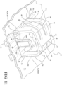
- FIG. 11 a flush mount retainer assembly 20 in accordance with a fourth embodiment of the present disclosure is illustrated.
- the flush mount retainer assembly 20 of Figure 11 is structurally and functionally similar to the flush mount retainer assembly of Figures 1-8 , except that the side retention members 42D (not shown), 42D' extend upwardly from the base 26, rather than downwardly from the front support member 32.
- the side retention members 42D, 42D' include ramped projections 56 (not shown), 56' to facilitate insertion of the flush mount retainer assembly 20 in the panel opening 24.
- the side retention members 42D are resiliently flexible, such that they deflect inwardly to provide an interference fit within panel openings having a depth greater than the second distance separating the base 26 from the lowermost portion 60 (not shown), 60' of the ramped projections 56, 56' of the side retention members 42D, 42D'.
- the side retention members 42D, 42D' are versatile and can function with panels 22 having a variety of different thicknesses, and thus defining panel openings 24 of varying depths.
- panel openings 24 having a depth less than the second distance, the lowermost portion 60, 60' of the ramped projections 56, 56'extend over the panel 22 and prevent withdrawal of a seated flush mount retainer assembly 20 from the panel opening 24, and further function to minimize slop of the flush mount retainer assembly 20 prior to the fastener 30 being engaged with (e.g. driven through) the threaded bore 28.
- flush mount retainer assembly 20 is suitable for use in securing the component 74 to the panel 22 having the panel opening 24.
- the term “flush” may refer to a general or specific orientation and proximity of the base 26 of the flush mount retainer assembly 20 as compared to a surface of the panel 22 (e.g., whether partially or fully adjacent to one another). In this sense, it is to be understood that the term “flush” may be used in either a descriptive or functional manner.
- the flush mount retainer assembly 20 may be disposed (i.e., inserted) only partially into the panel opening 24 of the panel 22 such that a bottom surface of the base 26 is not co-planar with a bottom surface of the panel 22 (such as shown in Figures 1 , 5-7 , and 9-11 ). Additionally, the flush mount retainer assembly 20 may be disposed (i.e., inserted) completely into the panel opening 24 of the panel 22 such that the bottom surface of the base 26 is coplanar with the surface of the panel 22 (e.g., when the panel opening is sized to accept the base 26 of the flush mount retainer assembly 20).
- the various elements of the flush mount retainer assembly 20, as described above, may be manufactured of the same material, different materials, or different alloys or mixes of materials. Moreover, each element may itself comprise a combination of different materials and not necessarily have a homogeneous composition throughout.
- the various elements of the flush mount retainer assembly 20 are manufactured of a material suitable to achieve the physical properties and performance demanded by the intended use and function of each element.
- the entirety of the flush mount retainer assembly 20 can be manufactured of the same plastic or metal material, for example steel.
- myriad materials may be used to manufacture the elements of the flush mount retainer assembly 20, typically a function of at least availability, cost, and performance/end use application, and plastics and metals are not exhaustive of suitable materials that may be used.
- the term “vertical” is used in the general sense and not the absolute sense and, therefore, includes a range of relative geometric configurations between two elements that may reasonably be understood as “vertical” and is not meant to necessarily imply orthogonality.
- the term “horizontal” similarly encompasses a range of relative geometric configurations between elements and does not necessarily imply parallelity or orthogonality in an absolute sense but, rather, encompasses a range of relative geometrical orientations reasonably understood as falling within the general category of horizontality.
Landscapes
- Engineering & Computer Science (AREA)
- General Engineering & Computer Science (AREA)
- Mechanical Engineering (AREA)
- Connection Of Plates (AREA)
Claims (6)
- Bündig montierte Halteanordnung (20), angepasst zur Aufnahme in einer Plattenöffnung (24), wobei die bündig montierte Halteanordnung (20) umfasst:eine eine Bohrung (28) zur Aufnahme eines Befestigungselements (30) definierende Basis (26);ein vorderes Stützelement (32) und ein hinteres Stützelement (34), wobei das vordere Stützelement (32) und das hintere Stützelement (34) jeweils einen mit der Basis (26) verbundenen vertikalen Abschnitt (36, 36') und einen sich vom vertikalen Abschnitt (36, 36') und wenigstens teilweise über der Bohrung (28) liegenden erstreckenden horizontalen Abschnitt (38, 38') umfassen, wobei vorderes und hinteres Stützelement nach außen elastisch flexibel als Reaktion auf den Eingriff des Befestigungselements in die Bohrung sind;ein sich vom vorderen Stützelement (32) erstreckendes vorderes Halteelement (40) und ein sich vom hinteren Stützelement (34) erstreckendes hinteres Halteelement (40'), um die Bewegung der bündig montierten Halteanordnung (20) in Bezug auf die Platte (22) vor dem Eingriff des Befestigungselements (30) in der Bohrung (28) zu begrenzen;ein Halteelement (42A) an der ersten Seite, angeordnet zwischen dem vertikalen Abschnitt (36) des vorderen Stützelements (32) und dem vertikalen Abschnitt (36') des hinteren Stützelements (34) zum Herstellen einer Presspassung mit einem ersten Rand (44) der Plattenöffnung (24); undein Halteelement (42A') an der zweiten Seite, angeordnet zwischen dem vertikalen Abschnitt (36) des vorderen Stützelements (32) und dem vertikalen Abschnitt (36') des hinteren Stützelements (34) zum Herstellen einer Presspassung mit einem zweiten Rand (46) der Plattenöffnung (24) gegenüber dem ersten Rand (44) der Plattenöffnung (24);wobei sich das Halteelement (42A) an der ersten Seite und das Halteelement (42A') an der zweiten Seite jeweils zu einem ersten Anschlussende (60) und einem zweiten Anschlussende (60') erstrecken, die sich nach außen in Bezug auf die Bohrung (28) neigen.
- Bündig montierte Halteanordnung (20) nach Anspruch 1, wobei sich das Halteelement (42A) an der ersten Seite und das Halteelement (42A') an der zweiten Seite jeweils von einem Außenrand (48) des horizontalen Abschnitts (38) des vorderen Stützelements (32) erstrecken oder wobei sich das Haltelement (42A) an der ersten Seite und das Halteelement (42A') an der zweiten Seite jeweils von einem Außenrand (50) des vertikalen Abschnitts (36) des vorderen Stützelements (32) erstrecken.
- Bündig montierte Halteanordnung (20) nach Anspruch 1, wobei sich das Halteelement (42A) an der ersten Seite und das Halteelement (42A') an der zweiten Seite jeweils von einem Außenrand (48') des horizontalen Abschnitts (38') des hinteren Stützelements (34) erstrecken oder wobei sich das Haltelement (42A) an der ersten Seite und das Halteelement (42A') an der zweiten Seite jeweils von einem Außenrand (50') des vertikalen Abschnitts (36') des hinteren Stützelements (34) erstrecken.
- Bündig montierte Halteanordnung (20) nach Anspruch 1, wobei sich das Halteelement (42A) an der ersten Seite und das Halteelement (42A') an der zweiten Seite jeweils von der Basis (26) der bündig montierten Halteanordnung (20) erstrecken.
- Bündig montierte Halteanordnung (20) nach einem der Ansprüche 1 bis 4, wobei das Halteelement (42A) an der ersten Seite und das Halteelement (42A') an der zweiten Seite jeweils eine Presspassung mit der Platte (22) an einem Punkt, der proximaler zur Basis (26) ist als ein Punkt, an dem vorderes und hinteres Haltelement (40, 40') enden, herstellen.
- Bündig montierte Halteanordnung (20) nach einem der Ansprüche 1 bis 5, wobei ein vorderes Stützelement (32) ein Paar von vorderen Stützbeinen (62) in beabstandeter Beziehung zueinander umfasst und das hintere Stützelement (34) ein Paar von hinteren Stützbeinen (64) in beabstandeter Beziehung zueinander umfasst.
Applications Claiming Priority (1)
| Application Number | Priority Date | Filing Date | Title |
|---|---|---|---|
| US15/902,458 US10837481B2 (en) | 2018-02-22 | 2018-02-22 | Flush mount retainer assembly |
Publications (2)
| Publication Number | Publication Date |
|---|---|
| EP3530964A1 EP3530964A1 (de) | 2019-08-28 |
| EP3530964B1 true EP3530964B1 (de) | 2023-11-29 |
Family
ID=65529454
Family Applications (1)
| Application Number | Title | Priority Date | Filing Date |
|---|---|---|---|
| EP19158418.4A Active EP3530964B1 (de) | 2018-02-22 | 2019-02-21 | Bündig montierte halteanordnung |
Country Status (3)
| Country | Link |
|---|---|
| US (1) | US10837481B2 (de) |
| EP (1) | EP3530964B1 (de) |
| CN (1) | CN110185683B (de) |
Families Citing this family (4)
| Publication number | Priority date | Publication date | Assignee | Title |
|---|---|---|---|---|
| CN110388371A (zh) * | 2018-04-18 | 2019-10-29 | 伊利诺斯工具制品有限公司 | 一种螺母紧固夹和螺母紧固夹组件 |
| US11629742B2 (en) * | 2018-06-19 | 2023-04-18 | Illinois Tool Works Inc. | Box nut retainer |
| GB2581539B (en) * | 2019-03-08 | 2021-03-03 | Goodenough Christopher | Wall fixing device |
| US20210062855A1 (en) * | 2019-08-27 | 2021-03-04 | Illinois Tool Works Inc. | Ergonomic Box Nut Retainer |
Family Cites Families (45)
| Publication number | Priority date | Publication date | Assignee | Title |
|---|---|---|---|---|
| US2571394A (en) | 1947-06-13 | 1951-10-16 | United Carr Fastener Corp | Mounting for fastening members and the like |
| US3486158A (en) * | 1967-09-29 | 1969-12-23 | Illinois Tool Works | Grounding clip |
| GB1217382A (en) | 1968-05-07 | 1970-12-31 | Carr Fastener Co Ltd | Sheet metal nut for assembly in an aperture in a support |
| US4300865A (en) * | 1979-07-11 | 1981-11-17 | Trw Inc. | Blind clip fastener |
| US4595325A (en) | 1984-09-28 | 1986-06-17 | Eaton Corporation | Self-locking prevailing torque fastener |
| JPH0310408Y2 (de) | 1987-02-28 | 1991-03-14 | ||
| US4925351A (en) * | 1989-03-21 | 1990-05-15 | Trw, Inc. | Push-in fastener clip |
| US5249900A (en) | 1992-09-18 | 1993-10-05 | California Industrial Products, Inc. | Threaded fastener for mounting within an opening in a panel |
| US5533237A (en) | 1994-09-12 | 1996-07-09 | Emhart, Inc. | Grommet fastener assembly for automobiles |
| US5873690A (en) | 1998-01-22 | 1999-02-23 | Eaton Corporation | Thread nut expansion fastener |
| US6524044B1 (en) | 1999-11-23 | 2003-02-25 | Wtpa, Incorporated | Fastener of high prevailing torque, pulling force, and stripping torque |
| US6164885A (en) | 1999-11-26 | 2000-12-26 | American Engineered Components, Inc. | Insert fastener |
| US6280129B1 (en) | 1999-12-22 | 2001-08-28 | Wtpa, Incorporated | Extensive engagement fastener |
| JP2001234988A (ja) | 2000-02-22 | 2001-08-31 | Harmonic Drive Technologies-Teijin Seiki Boston Inc | ハーモニック駆動ベアリング構造 |
| JP4549476B2 (ja) * | 2000-02-24 | 2010-09-22 | 株式会社東郷製作所 | クリップ |
| US6409443B1 (en) | 2000-09-20 | 2002-06-25 | Wtpa, Incorporated | Spring fastener with Y-shaped cut as funnel |
| US6629809B2 (en) | 2000-11-08 | 2003-10-07 | Termax Corporation | Sheet metal fastener with multiple engagement |
| US6908274B1 (en) | 2000-11-20 | 2005-06-21 | Termax Corporation | Combination fastener |
| JP3699048B2 (ja) | 2001-02-01 | 2005-09-28 | ハン イル エ ワ カンパニーリミテッド | 物品装着用クリップ |
| US7784159B2 (en) | 2002-06-07 | 2010-08-31 | Termax Corporation | Fastener with ergonomic removal to insertion force ratio |
| US6726418B2 (en) | 2001-09-19 | 2004-04-27 | Eustathios Vassiliou Revocable Trust | Spring fastener for connecting automotive components and other articles |
| US10336265B2 (en) * | 2015-10-21 | 2019-07-02 | Termax Llc | Fastener clip over a carrier secured with hooks |
| US20040049894A1 (en) | 2002-06-24 | 2004-03-18 | Nicholas Jackson | Sheet metal fastening clip |
| US20040244156A1 (en) | 2002-06-24 | 2004-12-09 | Nicholas Jackson | Sheet metal fastening clip |
| US7226260B2 (en) | 2002-06-24 | 2007-06-05 | A. Raymond, Inc. | Sheet metal fastening clip |
| US7572089B2 (en) * | 2002-08-01 | 2009-08-11 | Termax Corporation | Spring fastener having stabilizing barbs |
| US6896461B2 (en) | 2002-08-06 | 2005-05-24 | E. Vassiliou Revo Cable Tryst | Spring fastener for substrates of various thicknesses and respective vehicles |
| DE20319556U1 (de) | 2003-12-17 | 2004-03-11 | A. Raymond & Cie | Vorrichtung zum Verbinden eines Trägerteiles mit einem Anbauteil |
| US7086125B2 (en) | 2004-04-23 | 2006-08-08 | Newfrey Llc | Multiple stage assembly assist fastener |
| DE102005060137B4 (de) | 2005-12-16 | 2008-09-11 | A. Raymond Et Cie | Blechmutter |
| DE102006001741A1 (de) | 2006-01-13 | 2007-08-02 | A. Raymond Et Cie | Steckmutter |
| KR100808846B1 (ko) | 2007-05-23 | 2008-03-03 | 엔브이에이치코리아(주) | 자동차 내장용 부품 고정클립 |
| US8016530B2 (en) * | 2008-01-10 | 2011-09-13 | Illinois Tool Works Inc. | Panel fastener |
| ES2356761B1 (es) | 2009-07-31 | 2012-02-29 | Illinois Tools Works Inc. | Clip de techo para la fijación de accesorios a los paneles de los veh�?culos. |
| DE202009011986U1 (de) | 2009-08-28 | 2009-12-10 | Illinois Tool Works Inc., Glenview | Vorrichtung zur Verbindung zweier Bauteile |
| DE102010008458B4 (de) | 2010-02-18 | 2024-10-31 | A. Raymond Et Cie | Befestigungsvorrichtung |
| DE202011101112U1 (de) | 2011-02-02 | 2012-08-28 | A. Raymond Et Cie | Befestigungsvorrichtung |
| ES2440065B1 (es) * | 2012-04-27 | 2015-03-10 | Illinois Tool Works | Dispositivo de fijación rápida en paneles |
| JP6207930B2 (ja) | 2013-08-29 | 2017-10-04 | 大和化成工業株式会社 | 防水クリップ |
| CN103591110A (zh) | 2013-11-15 | 2014-02-19 | 上汽通用五菱汽车股份有限公司 | 一种螺母座 |
| CN203641234U (zh) | 2013-11-15 | 2014-06-11 | 上汽通用五菱汽车股份有限公司 | 一种螺母座 |
| US9631662B2 (en) | 2014-03-19 | 2017-04-25 | Ramco Specialties, Inc. | Spring clip apparatus |
| US9440596B2 (en) | 2014-11-20 | 2016-09-13 | Ford Global Technologies, Llc | Retention clip for interior vehicle components |
| US9562554B2 (en) | 2015-01-16 | 2017-02-07 | A. Raymond Et Cie | Retainer assembly |
| US9850934B2 (en) | 2016-03-07 | 2017-12-26 | A. Raymond Et Cie | Self-reinforcing clip |
-
2018
- 2018-02-22 US US15/902,458 patent/US10837481B2/en active Active
-
2019
- 2019-02-21 EP EP19158418.4A patent/EP3530964B1/de active Active
- 2019-02-22 CN CN201910132977.1A patent/CN110185683B/zh active Active
Also Published As
| Publication number | Publication date |
|---|---|
| CN110185683B (zh) | 2022-06-03 |
| US20190257339A1 (en) | 2019-08-22 |
| CN110185683A (zh) | 2019-08-30 |
| EP3530964A1 (de) | 2019-08-28 |
| BR102019003436A2 (pt) | 2019-09-03 |
| US10837481B2 (en) | 2020-11-17 |
Similar Documents
| Publication | Publication Date | Title |
|---|---|---|
| US7226260B2 (en) | Sheet metal fastening clip | |
| US6796006B2 (en) | Rib clip | |
| EP3530964A1 (de) | Bündig montierte halteanordnung | |
| US9562554B2 (en) | Retainer assembly | |
| US5410854A (en) | Connector brackets | |
| US9801477B2 (en) | Picture hanging bracket and method of installation | |
| JP4738323B2 (ja) | 締結具 | |
| US11577666B2 (en) | Arrowhead fastener clip with barbs | |
| EP2951366B1 (de) | Klammer für umfangsverkleidung | |
| US5667177A (en) | Spring snap clip | |
| US3279729A (en) | Fastener device and mounting assembly | |
| CN112392811B (zh) | 带倒钩的箭头紧固夹 | |
| US7640707B2 (en) | Fastening clip | |
| WO2017158423A1 (en) | U-clip assembly | |
| US20040244156A1 (en) | Sheet metal fastening clip | |
| EP3907410B1 (de) | Federklammer | |
| US6454230B1 (en) | Tool holder for use with a perforated support panel | |
| US3459396A (en) | Fastener device and mounting assembly | |
| EP0904496A1 (de) | Käfigmutter mit federwirkung | |
| US11486423B2 (en) | Linear latching systems and methods | |
| EP0683324A1 (de) | Federnde Schnappklammer | |
| US3033332A (en) | Fastener clip | |
| BR102019003436B1 (pt) | Conjunto de retentor de montagem nivelada | |
| US20070194195A1 (en) | Support bracket and kit of parts for a support assembly | |
| JPH0673419U (ja) | クリップ |
Legal Events
| Date | Code | Title | Description |
|---|---|---|---|
| PUAI | Public reference made under article 153(3) epc to a published international application that has entered the european phase |
Free format text: ORIGINAL CODE: 0009012 |
|
| STAA | Information on the status of an ep patent application or granted ep patent |
Free format text: STATUS: THE APPLICATION HAS BEEN PUBLISHED |
|
| AK | Designated contracting states |
Kind code of ref document: A1 Designated state(s): AL AT BE BG CH CY CZ DE DK EE ES FI FR GB GR HR HU IE IS IT LI LT LU LV MC MK MT NL NO PL PT RO RS SE SI SK SM TR |
|
| AX | Request for extension of the european patent |
Extension state: BA ME |
|
| STAA | Information on the status of an ep patent application or granted ep patent |
Free format text: STATUS: REQUEST FOR EXAMINATION WAS MADE |
|
| 17P | Request for examination filed |
Effective date: 20200226 |
|
| RBV | Designated contracting states (corrected) |
Designated state(s): AL AT BE BG CH CY CZ DE DK EE ES FI FR GB GR HR HU IE IS IT LI LT LU LV MC MK MT NL NO PL PT RO RS SE SI SK SM TR |
|
| STAA | Information on the status of an ep patent application or granted ep patent |
Free format text: STATUS: EXAMINATION IS IN PROGRESS |
|
| 17Q | First examination report despatched |
Effective date: 20211125 |
|
| GRAP | Despatch of communication of intention to grant a patent |
Free format text: ORIGINAL CODE: EPIDOSNIGR1 |
|
| STAA | Information on the status of an ep patent application or granted ep patent |
Free format text: STATUS: GRANT OF PATENT IS INTENDED |
|
| INTG | Intention to grant announced |
Effective date: 20230622 |
|
| GRAS | Grant fee paid |
Free format text: ORIGINAL CODE: EPIDOSNIGR3 |
|
| GRAA | (expected) grant |
Free format text: ORIGINAL CODE: 0009210 |
|
| STAA | Information on the status of an ep patent application or granted ep patent |
Free format text: STATUS: THE PATENT HAS BEEN GRANTED |
|
| P01 | Opt-out of the competence of the unified patent court (upc) registered |
Effective date: 20231011 |
|
| AK | Designated contracting states |
Kind code of ref document: B1 Designated state(s): AL AT BE BG CH CY CZ DE DK EE ES FI FR GB GR HR HU IE IS IT LI LT LU LV MC MK MT NL NO PL PT RO RS SE SI SK SM TR |
|
| REG | Reference to a national code |
Ref country code: GB Ref legal event code: FG4D |
|
| REG | Reference to a national code |
Ref country code: CH Ref legal event code: EP |
|
| REG | Reference to a national code |
Ref country code: DE Ref legal event code: R096 Ref document number: 602019042185 Country of ref document: DE |
|
| REG | Reference to a national code |
Ref country code: IE Ref legal event code: FG4D |
|
| REG | Reference to a national code |
Ref country code: LT Ref legal event code: MG9D |
|
| REG | Reference to a national code |
Ref country code: NL Ref legal event code: MP Effective date: 20231129 |
|
| PG25 | Lapsed in a contracting state [announced via postgrant information from national office to epo] |
Ref country code: GR Free format text: LAPSE BECAUSE OF FAILURE TO SUBMIT A TRANSLATION OF THE DESCRIPTION OR TO PAY THE FEE WITHIN THE PRESCRIBED TIME-LIMIT Effective date: 20240301 |
|
| PG25 | Lapsed in a contracting state [announced via postgrant information from national office to epo] |
Ref country code: IS Free format text: LAPSE BECAUSE OF FAILURE TO SUBMIT A TRANSLATION OF THE DESCRIPTION OR TO PAY THE FEE WITHIN THE PRESCRIBED TIME-LIMIT Effective date: 20240329 |
|
| PG25 | Lapsed in a contracting state [announced via postgrant information from national office to epo] |
Ref country code: LT Free format text: LAPSE BECAUSE OF FAILURE TO SUBMIT A TRANSLATION OF THE DESCRIPTION OR TO PAY THE FEE WITHIN THE PRESCRIBED TIME-LIMIT Effective date: 20231129 |
|
| PG25 | Lapsed in a contracting state [announced via postgrant information from national office to epo] |
Ref country code: ES Free format text: LAPSE BECAUSE OF FAILURE TO SUBMIT A TRANSLATION OF THE DESCRIPTION OR TO PAY THE FEE WITHIN THE PRESCRIBED TIME-LIMIT Effective date: 20231129 |
|
| PG25 | Lapsed in a contracting state [announced via postgrant information from national office to epo] |
Ref country code: LT Free format text: LAPSE BECAUSE OF FAILURE TO SUBMIT A TRANSLATION OF THE DESCRIPTION OR TO PAY THE FEE WITHIN THE PRESCRIBED TIME-LIMIT Effective date: 20231129 Ref country code: IS Free format text: LAPSE BECAUSE OF FAILURE TO SUBMIT A TRANSLATION OF THE DESCRIPTION OR TO PAY THE FEE WITHIN THE PRESCRIBED TIME-LIMIT Effective date: 20240329 Ref country code: GR Free format text: LAPSE BECAUSE OF FAILURE TO SUBMIT A TRANSLATION OF THE DESCRIPTION OR TO PAY THE FEE WITHIN THE PRESCRIBED TIME-LIMIT Effective date: 20240301 Ref country code: ES Free format text: LAPSE BECAUSE OF FAILURE TO SUBMIT A TRANSLATION OF THE DESCRIPTION OR TO PAY THE FEE WITHIN THE PRESCRIBED TIME-LIMIT Effective date: 20231129 Ref country code: BG Free format text: LAPSE BECAUSE OF FAILURE TO SUBMIT A TRANSLATION OF THE DESCRIPTION OR TO PAY THE FEE WITHIN THE PRESCRIBED TIME-LIMIT Effective date: 20240229 |
|
| REG | Reference to a national code |
Ref country code: AT Ref legal event code: MK05 Ref document number: 1636412 Country of ref document: AT Kind code of ref document: T Effective date: 20231129 |
|
| PG25 | Lapsed in a contracting state [announced via postgrant information from national office to epo] |
Ref country code: NL Free format text: LAPSE BECAUSE OF FAILURE TO SUBMIT A TRANSLATION OF THE DESCRIPTION OR TO PAY THE FEE WITHIN THE PRESCRIBED TIME-LIMIT Effective date: 20231129 |
|
| PG25 | Lapsed in a contracting state [announced via postgrant information from national office to epo] |
Ref country code: SE Free format text: LAPSE BECAUSE OF FAILURE TO SUBMIT A TRANSLATION OF THE DESCRIPTION OR TO PAY THE FEE WITHIN THE PRESCRIBED TIME-LIMIT Effective date: 20231129 Ref country code: RS Free format text: LAPSE BECAUSE OF FAILURE TO SUBMIT A TRANSLATION OF THE DESCRIPTION OR TO PAY THE FEE WITHIN THE PRESCRIBED TIME-LIMIT Effective date: 20231129 Ref country code: PL Free format text: LAPSE BECAUSE OF FAILURE TO SUBMIT A TRANSLATION OF THE DESCRIPTION OR TO PAY THE FEE WITHIN THE PRESCRIBED TIME-LIMIT Effective date: 20231129 Ref country code: NO Free format text: LAPSE BECAUSE OF FAILURE TO SUBMIT A TRANSLATION OF THE DESCRIPTION OR TO PAY THE FEE WITHIN THE PRESCRIBED TIME-LIMIT Effective date: 20240229 Ref country code: NL Free format text: LAPSE BECAUSE OF FAILURE TO SUBMIT A TRANSLATION OF THE DESCRIPTION OR TO PAY THE FEE WITHIN THE PRESCRIBED TIME-LIMIT Effective date: 20231129 Ref country code: LV Free format text: LAPSE BECAUSE OF FAILURE TO SUBMIT A TRANSLATION OF THE DESCRIPTION OR TO PAY THE FEE WITHIN THE PRESCRIBED TIME-LIMIT Effective date: 20231129 Ref country code: HR Free format text: LAPSE BECAUSE OF FAILURE TO SUBMIT A TRANSLATION OF THE DESCRIPTION OR TO PAY THE FEE WITHIN THE PRESCRIBED TIME-LIMIT Effective date: 20231129 |
|
| PG25 | Lapsed in a contracting state [announced via postgrant information from national office to epo] |
Ref country code: DK Free format text: LAPSE BECAUSE OF FAILURE TO SUBMIT A TRANSLATION OF THE DESCRIPTION OR TO PAY THE FEE WITHIN THE PRESCRIBED TIME-LIMIT Effective date: 20231129 |
|
| PG25 | Lapsed in a contracting state [announced via postgrant information from national office to epo] |
Ref country code: AT Free format text: LAPSE BECAUSE OF FAILURE TO SUBMIT A TRANSLATION OF THE DESCRIPTION OR TO PAY THE FEE WITHIN THE PRESCRIBED TIME-LIMIT Effective date: 20231129 Ref country code: CZ Free format text: LAPSE BECAUSE OF FAILURE TO SUBMIT A TRANSLATION OF THE DESCRIPTION OR TO PAY THE FEE WITHIN THE PRESCRIBED TIME-LIMIT Effective date: 20231129 |
|
| PG25 | Lapsed in a contracting state [announced via postgrant information from national office to epo] |
Ref country code: SK Free format text: LAPSE BECAUSE OF FAILURE TO SUBMIT A TRANSLATION OF THE DESCRIPTION OR TO PAY THE FEE WITHIN THE PRESCRIBED TIME-LIMIT Effective date: 20231129 |
|
| PG25 | Lapsed in a contracting state [announced via postgrant information from national office to epo] |
Ref country code: SM Free format text: LAPSE BECAUSE OF FAILURE TO SUBMIT A TRANSLATION OF THE DESCRIPTION OR TO PAY THE FEE WITHIN THE PRESCRIBED TIME-LIMIT Effective date: 20231129 Ref country code: SK Free format text: LAPSE BECAUSE OF FAILURE TO SUBMIT A TRANSLATION OF THE DESCRIPTION OR TO PAY THE FEE WITHIN THE PRESCRIBED TIME-LIMIT Effective date: 20231129 Ref country code: RO Free format text: LAPSE BECAUSE OF FAILURE TO SUBMIT A TRANSLATION OF THE DESCRIPTION OR TO PAY THE FEE WITHIN THE PRESCRIBED TIME-LIMIT Effective date: 20231129 Ref country code: IT Free format text: LAPSE BECAUSE OF FAILURE TO SUBMIT A TRANSLATION OF THE DESCRIPTION OR TO PAY THE FEE WITHIN THE PRESCRIBED TIME-LIMIT Effective date: 20231129 Ref country code: EE Free format text: LAPSE BECAUSE OF FAILURE TO SUBMIT A TRANSLATION OF THE DESCRIPTION OR TO PAY THE FEE WITHIN THE PRESCRIBED TIME-LIMIT Effective date: 20231129 Ref country code: DK Free format text: LAPSE BECAUSE OF FAILURE TO SUBMIT A TRANSLATION OF THE DESCRIPTION OR TO PAY THE FEE WITHIN THE PRESCRIBED TIME-LIMIT Effective date: 20231129 Ref country code: CZ Free format text: LAPSE BECAUSE OF FAILURE TO SUBMIT A TRANSLATION OF THE DESCRIPTION OR TO PAY THE FEE WITHIN THE PRESCRIBED TIME-LIMIT Effective date: 20231129 Ref country code: AT Free format text: LAPSE BECAUSE OF FAILURE TO SUBMIT A TRANSLATION OF THE DESCRIPTION OR TO PAY THE FEE WITHIN THE PRESCRIBED TIME-LIMIT Effective date: 20231129 |
|
| PG25 | Lapsed in a contracting state [announced via postgrant information from national office to epo] |
Ref country code: PT Free format text: LAPSE BECAUSE OF FAILURE TO SUBMIT A TRANSLATION OF THE DESCRIPTION OR TO PAY THE FEE WITHIN THE PRESCRIBED TIME-LIMIT Effective date: 20240401 |
|
| PG25 | Lapsed in a contracting state [announced via postgrant information from national office to epo] |
Ref country code: PT Free format text: LAPSE BECAUSE OF FAILURE TO SUBMIT A TRANSLATION OF THE DESCRIPTION OR TO PAY THE FEE WITHIN THE PRESCRIBED TIME-LIMIT Effective date: 20240401 |
|
| REG | Reference to a national code |
Ref country code: DE Ref legal event code: R097 Ref document number: 602019042185 Country of ref document: DE |
|
| PG25 | Lapsed in a contracting state [announced via postgrant information from national office to epo] |
Ref country code: MC Free format text: LAPSE BECAUSE OF FAILURE TO SUBMIT A TRANSLATION OF THE DESCRIPTION OR TO PAY THE FEE WITHIN THE PRESCRIBED TIME-LIMIT Effective date: 20231129 |
|
| REG | Reference to a national code |
Ref country code: CH Ref legal event code: PL |
|
| PLBE | No opposition filed within time limit |
Free format text: ORIGINAL CODE: 0009261 |
|
| STAA | Information on the status of an ep patent application or granted ep patent |
Free format text: STATUS: NO OPPOSITION FILED WITHIN TIME LIMIT |
|
| PG25 | Lapsed in a contracting state [announced via postgrant information from national office to epo] |
Ref country code: LU Free format text: LAPSE BECAUSE OF NON-PAYMENT OF DUE FEES Effective date: 20240221 |
|
| PG25 | Lapsed in a contracting state [announced via postgrant information from national office to epo] |
Ref country code: CH Free format text: LAPSE BECAUSE OF NON-PAYMENT OF DUE FEES Effective date: 20240229 |
|
| GBPC | Gb: european patent ceased through non-payment of renewal fee |
Effective date: 20240229 |
|
| PG25 | Lapsed in a contracting state [announced via postgrant information from national office to epo] |
Ref country code: SI Free format text: LAPSE BECAUSE OF FAILURE TO SUBMIT A TRANSLATION OF THE DESCRIPTION OR TO PAY THE FEE WITHIN THE PRESCRIBED TIME-LIMIT Effective date: 20231129 |
|
| PG25 | Lapsed in a contracting state [announced via postgrant information from national office to epo] |
Ref country code: SI Free format text: LAPSE BECAUSE OF FAILURE TO SUBMIT A TRANSLATION OF THE DESCRIPTION OR TO PAY THE FEE WITHIN THE PRESCRIBED TIME-LIMIT Effective date: 20231129 Ref country code: LU Free format text: LAPSE BECAUSE OF NON-PAYMENT OF DUE FEES Effective date: 20240221 Ref country code: CH Free format text: LAPSE BECAUSE OF NON-PAYMENT OF DUE FEES Effective date: 20240229 |
|
| 26N | No opposition filed |
Effective date: 20240830 |
|
| REG | Reference to a national code |
Ref country code: BE Ref legal event code: MM Effective date: 20240229 |
|
| PG25 | Lapsed in a contracting state [announced via postgrant information from national office to epo] |
Ref country code: BE Free format text: LAPSE BECAUSE OF NON-PAYMENT OF DUE FEES Effective date: 20240229 |
|
| PG25 | Lapsed in a contracting state [announced via postgrant information from national office to epo] |
Ref country code: GB Free format text: LAPSE BECAUSE OF NON-PAYMENT OF DUE FEES Effective date: 20240229 |
|
| PG25 | Lapsed in a contracting state [announced via postgrant information from national office to epo] |
Ref country code: FR Free format text: LAPSE BECAUSE OF NON-PAYMENT OF DUE FEES Effective date: 20240229 |
|
| PG25 | Lapsed in a contracting state [announced via postgrant information from national office to epo] |
Ref country code: IE Free format text: LAPSE BECAUSE OF NON-PAYMENT OF DUE FEES Effective date: 20240221 |
|
| PG25 | Lapsed in a contracting state [announced via postgrant information from national office to epo] |
Ref country code: IE Free format text: LAPSE BECAUSE OF NON-PAYMENT OF DUE FEES Effective date: 20240221 Ref country code: GB Free format text: LAPSE BECAUSE OF NON-PAYMENT OF DUE FEES Effective date: 20240229 Ref country code: FR Free format text: LAPSE BECAUSE OF NON-PAYMENT OF DUE FEES Effective date: 20240229 Ref country code: BE Free format text: LAPSE BECAUSE OF NON-PAYMENT OF DUE FEES Effective date: 20240229 |
|
| PG25 | Lapsed in a contracting state [announced via postgrant information from national office to epo] |
Ref country code: CY Free format text: LAPSE BECAUSE OF FAILURE TO SUBMIT A TRANSLATION OF THE DESCRIPTION OR TO PAY THE FEE WITHIN THE PRESCRIBED TIME-LIMIT; INVALID AB INITIO Effective date: 20190221 |
|
| PG25 | Lapsed in a contracting state [announced via postgrant information from national office to epo] |
Ref country code: HU Free format text: LAPSE BECAUSE OF FAILURE TO SUBMIT A TRANSLATION OF THE DESCRIPTION OR TO PAY THE FEE WITHIN THE PRESCRIBED TIME-LIMIT; INVALID AB INITIO Effective date: 20190221 |
|
| PG25 | Lapsed in a contracting state [announced via postgrant information from national office to epo] |
Ref country code: FI Free format text: LAPSE BECAUSE OF FAILURE TO SUBMIT A TRANSLATION OF THE DESCRIPTION OR TO PAY THE FEE WITHIN THE PRESCRIBED TIME-LIMIT Effective date: 20231129 |
|
| PG25 | Lapsed in a contracting state [announced via postgrant information from national office to epo] |
Ref country code: TR Free format text: LAPSE BECAUSE OF FAILURE TO SUBMIT A TRANSLATION OF THE DESCRIPTION OR TO PAY THE FEE WITHIN THE PRESCRIBED TIME-LIMIT Effective date: 20231129 |
|
| PGFP | Annual fee paid to national office [announced via postgrant information from national office to epo] |
Ref country code: DE Payment date: 20260218 Year of fee payment: 8 |