EP3530980A1 - Schwingungsdämpfendes trägersystem - Google Patents
Schwingungsdämpfendes trägersystem Download PDFInfo
- Publication number
- EP3530980A1 EP3530980A1 EP17862173.6A EP17862173A EP3530980A1 EP 3530980 A1 EP3530980 A1 EP 3530980A1 EP 17862173 A EP17862173 A EP 17862173A EP 3530980 A1 EP3530980 A1 EP 3530980A1
- Authority
- EP
- European Patent Office
- Prior art keywords
- upper base
- fixed mount
- protected
- mount
- floating
- Prior art date
- Legal status (The legal status is an assumption and is not a legal conclusion. Google has not performed a legal analysis and makes no representation as to the accuracy of the status listed.)
- Granted
Links
Images


Classifications
-
- F—MECHANICAL ENGINEERING; LIGHTING; HEATING; WEAPONS; BLASTING
- F16—ENGINEERING ELEMENTS AND UNITS; GENERAL MEASURES FOR PRODUCING AND MAINTAINING EFFECTIVE FUNCTIONING OF MACHINES OR INSTALLATIONS; THERMAL INSULATION IN GENERAL
- F16F—SPRINGS; SHOCK-ABSORBERS; MEANS FOR DAMPING VIBRATION
- F16F15/00—Suppression of vibrations in systems; Means or arrangements for avoiding or reducing out-of-balance forces, e.g. due to motion
- F16F15/02—Suppression of vibrations of non-rotating, e.g. reciprocating systems; Suppression of vibrations of rotating systems by use of members not moving with the rotating systems
- F16F15/022—Suppression of vibrations of non-rotating, e.g. reciprocating systems; Suppression of vibrations of rotating systems by use of members not moving with the rotating systems using dampers and springs in combination
-
- F—MECHANICAL ENGINEERING; LIGHTING; HEATING; WEAPONS; BLASTING
- F16—ENGINEERING ELEMENTS AND UNITS; GENERAL MEASURES FOR PRODUCING AND MAINTAINING EFFECTIVE FUNCTIONING OF MACHINES OR INSTALLATIONS; THERMAL INSULATION IN GENERAL
- F16F—SPRINGS; SHOCK-ABSORBERS; MEANS FOR DAMPING VIBRATION
- F16F15/00—Suppression of vibrations in systems; Means or arrangements for avoiding or reducing out-of-balance forces, e.g. due to motion
- F16F15/02—Suppression of vibrations of non-rotating, e.g. reciprocating systems; Suppression of vibrations of rotating systems by use of members not moving with the rotating systems
- F16F15/04—Suppression of vibrations of non-rotating, e.g. reciprocating systems; Suppression of vibrations of rotating systems by use of members not moving with the rotating systems using elastic means
-
- F—MECHANICAL ENGINEERING; LIGHTING; HEATING; WEAPONS; BLASTING
- F16—ENGINEERING ELEMENTS AND UNITS; GENERAL MEASURES FOR PRODUCING AND MAINTAINING EFFECTIVE FUNCTIONING OF MACHINES OR INSTALLATIONS; THERMAL INSULATION IN GENERAL
- F16F—SPRINGS; SHOCK-ABSORBERS; MEANS FOR DAMPING VIBRATION
- F16F15/00—Suppression of vibrations in systems; Means or arrangements for avoiding or reducing out-of-balance forces, e.g. due to motion
- F16F15/02—Suppression of vibrations of non-rotating, e.g. reciprocating systems; Suppression of vibrations of rotating systems by use of members not moving with the rotating systems
- F16F15/04—Suppression of vibrations of non-rotating, e.g. reciprocating systems; Suppression of vibrations of rotating systems by use of members not moving with the rotating systems using elastic means
- F16F15/06—Suppression of vibrations of non-rotating, e.g. reciprocating systems; Suppression of vibrations of rotating systems by use of members not moving with the rotating systems using elastic means with metal springs
- F16F15/067—Suppression of vibrations of non-rotating, e.g. reciprocating systems; Suppression of vibrations of rotating systems by use of members not moving with the rotating systems using elastic means with metal springs using only wound springs
-
- B—PERFORMING OPERATIONS; TRANSPORTING
- B64—AIRCRAFT; AVIATION; COSMONAUTICS
- B64C—AEROPLANES; HELICOPTERS
- B64C27/00—Rotorcraft; Rotors peculiar thereto
- B64C27/001—Vibration damping devices
-
- F—MECHANICAL ENGINEERING; LIGHTING; HEATING; WEAPONS; BLASTING
- F16—ENGINEERING ELEMENTS AND UNITS; GENERAL MEASURES FOR PRODUCING AND MAINTAINING EFFECTIVE FUNCTIONING OF MACHINES OR INSTALLATIONS; THERMAL INSULATION IN GENERAL
- F16F—SPRINGS; SHOCK-ABSORBERS; MEANS FOR DAMPING VIBRATION
- F16F7/00—Vibration-dampers; Shock-absorbers
-
- F—MECHANICAL ENGINEERING; LIGHTING; HEATING; WEAPONS; BLASTING
- F25—REFRIGERATION OR COOLING; COMBINED HEATING AND REFRIGERATION SYSTEMS; HEAT PUMP SYSTEMS; MANUFACTURE OR STORAGE OF ICE; LIQUEFACTION SOLIDIFICATION OF GASES
- F25B—REFRIGERATION MACHINES, PLANTS OR SYSTEMS; COMBINED HEATING AND REFRIGERATION SYSTEMS; HEAT PUMP SYSTEMS
- F25B2500/00—Problems to be solved
- F25B2500/13—Vibrations
-
- H—ELECTRICITY
- H02—GENERATION; CONVERSION OR DISTRIBUTION OF ELECTRIC POWER
- H02B—BOARDS, SUBSTATIONS OR SWITCHING ARRANGEMENTS FOR THE SUPPLY OR DISTRIBUTION OF ELECTRIC POWER
- H02B1/00—Frameworks, boards, panels, desks, casings; Details of substations or switching arrangements
- H02B1/54—Anti-seismic devices or installations
Definitions
- the present invention relates to an anti-vibration support system, applicable in the protection of various apparatuses and, in particular, computer equipment, electronic equipment from data-processing centres, laboratory equipment and, in general, any sensitive equipment requiring protection against seismic movements and intense vibrations of any kind.
- These floating slabs are mainly used to prevent the transmission of vibrations or noises produced by the operation of apparatuses or machines to the building or structure.
- the applicant of this invention is the holder of the Spanish patent ES 2 315 182 B1 concerning a device for positioning on floating slabs and installation system thereof.
- floating slabs of this type are not suitable for the protection of certain vibration-sensitive apparatuses, such as computer equipment, equipment from data protection centres with networked servers or hard drives for mass data storage, against seismic movements.
- these apparatuses are located in cabinets or shelves, internationally called “racks", which are independent but in contact with each other at their sides, and can be arranged in the room forming one or more rows.
- these floating slabs do not provide adequate protection to the apparatuses positioned on them since they are designed to prevent the transmission of vibrations from the apparatuses to the building and not the other way around; moreover, these floating slabs constitute only a base for the apparatuses to be protected to rest thereon and do not provide any fastening of said apparatuses on their upper area.
- the object of the invention is an anti-vibration support system intended to be positioned on the ground or other resistant surface and to provide apparatuses positioned thereon with effective protection against seismic movements and vibrations of any nature.
- the system comprises:
- the upper base together with the side structures provide stability to the apparatuses mounted on the floating mount, limiting their vertical movement, minimising damage thereof in the event of an earthquake, and preventing their fall or tipping sideways.
- the floating mount is capable of limited movement in three perpendicular axes X, Y, Z and is supported by lower elastic elements acting for absorbing and minimising the transmission of vertical movements, and side elastic elements arranged between said floating mount and the fixed mount; said side elastic elements limiting the movement of the floating mount on the X-Y plane.
- the fixed mount is anchored to the ground or other resistant surface; and limits, together with the side elastic elements, the lateral movement of the floating mount on the X-Y plane;
- the side structures comprise at least one tilted bar connected by damping elements to the upper base and to the fixed mount of the lower base; said side structures limiting the movement of the upper base and the apparatus to be protected, thereby achieving the object of the invention.
- the anti-vibration support system comprises:
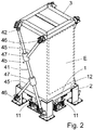
- the floating mount (1) forms a resting surface for the apparatus (E) to be protected with possibility of limited movement on three perpendicular axes X, Y, Z.
- Said floating mount (1) is supported by lower elastic elements (11) and by side elastic elements (12) arranged between the floating mount (1) and the fixed mount (2).
- the lower (11) and side (12) elastic elements comprise springs.
- the fixed mount (2) is anchored to the ground or other resistant surface; and together with the side elastic elements (12) acts for limiting the lateral movement of the floating mount (1) on the X-Y plane.
- the upper base (3) is intended to rest on the apparatus (E) to be protected, and to limit its movement in the vertical direction, preventing it from being released from the floating mount (1) in the event that the support is subjected to strong vibrations, for example, due to an earthquake.
- the system comprises, on two opposite sides, two side structures (4a) that relate the upper base (3) to the fixed mount (2) of the lower base.
- Each of the side structures (4a) comprises two tilted bars (41, 43), in the form of an "X”, joined together by their intermediate area (44), and attached, at the opposite ends, to the fixed mount (2) and the upper base (3) by damping elements (42).
- the apparatus (E) to be protected is computer equipment that has been schematically represented.
- the system comprises two side structures (4b) arranged on two opposite sides of the system.
- Each of the side structures (4b) comprises: a tilted bar (41) joined at its ends to the fixed mount (2) and to the upper base (3) by damping elements (42); and two auxiliary bars (45) joined respectively, at one end, to the fixed mount (2) and to the upper base (3) by damping elements (46); said auxiliary bars (45) having, at their opposite ends, two ferrules (47) mounted with the possibility of movement on the tilted bar (41).
- Each of the auxiliary bars (45) defines with the tilted bar (41) a configuration in the form of a "Y" that allows a certain relative mobility of the upper base (3), limiting its vertical movement, but without reaching the rigidity of the side structure (4a) of Figure 1 .
- the tilted bar (41) and the auxiliary bars (45) of a same side structure 4b are arranged in a coplanar manner.
Landscapes
- Engineering & Computer Science (AREA)
- General Engineering & Computer Science (AREA)
- Physics & Mathematics (AREA)
- Acoustics & Sound (AREA)
- Aviation & Aerospace Engineering (AREA)
- Mechanical Engineering (AREA)
- Vibration Prevention Devices (AREA)
Applications Claiming Priority (2)
| Application Number | Priority Date | Filing Date | Title |
|---|---|---|---|
| ES201631359A ES2668978B1 (es) | 2016-10-21 | 2016-10-21 | Sistema de soporte antivibratorio. |
| PCT/ES2017/070701 WO2018073480A1 (es) | 2016-10-21 | 2017-10-20 | Sistema de soporte antivibratorio |
Publications (4)
| Publication Number | Publication Date |
|---|---|
| EP3530980A1 true EP3530980A1 (de) | 2019-08-28 |
| EP3530980A4 EP3530980A4 (de) | 2020-07-29 |
| EP3530980B1 EP3530980B1 (de) | 2025-07-16 |
| EP3530980C0 EP3530980C0 (de) | 2025-07-16 |
Family
ID=62018266
Family Applications (1)
| Application Number | Title | Priority Date | Filing Date |
|---|---|---|---|
| EP17862173.6A Active EP3530980B1 (de) | 2016-10-21 | 2017-10-20 | Schwingungsdämpfendes trägersystem |
Country Status (4)
| Country | Link |
|---|---|
| US (1) | US10718399B2 (de) |
| EP (1) | EP3530980B1 (de) |
| ES (1) | ES2668978B1 (de) |
| WO (1) | WO2018073480A1 (de) |
Cited By (1)
| Publication number | Priority date | Publication date | Assignee | Title |
|---|---|---|---|---|
| CN113224671A (zh) * | 2021-04-27 | 2021-08-06 | 泉州七星电气有限公司 | 一种抗震效果好的智能环保型固体绝缘环网柜 |
Families Citing this family (5)
| Publication number | Priority date | Publication date | Assignee | Title |
|---|---|---|---|---|
| US11590406B2 (en) * | 2017-04-13 | 2023-02-28 | Worcester Polytechnic Institute | Multi-mode load absorbing ski binding |
| CN109996417B (zh) * | 2019-02-20 | 2023-10-20 | 和信精密科技(吴江)有限公司 | 一种可拆式server |
| KR102286047B1 (ko) * | 2021-02-26 | 2021-08-05 | 주식회사 에너테크 | 마찰 댐퍼를 적용한 변위제어 내진형 변압기 |
| JP7739935B2 (ja) * | 2021-10-22 | 2025-09-17 | 富士フイルムビジネスイノベーション株式会社 | 緩衝部材、梱包材および梱包物 |
| CN121088930A (zh) * | 2024-06-06 | 2025-12-09 | 台达电子工业股份有限公司 | 抗扭力机台及其抗扭力装置 |
Family Cites Families (15)
| Publication number | Priority date | Publication date | Assignee | Title |
|---|---|---|---|---|
| US2900157A (en) * | 1955-11-28 | 1959-08-18 | Allis Chalmers Mfg Co | Frangible article shipping assembly |
| US2912212A (en) | 1956-05-11 | 1959-11-10 | Barry Controls Inc | Resilient support |
| US6530563B1 (en) * | 2001-07-10 | 2003-03-11 | Enidine, Incorporated | Multi-axis shock and vibration isolation system |
| ES2315182B1 (es) | 2007-07-13 | 2009-11-11 | Tejasa, S.L.L | Dispositivo para la colocacion en losas flotantes y su sistema de instalacion. |
| JP5537856B2 (ja) * | 2009-07-24 | 2014-07-02 | 株式会社田中制震構造研究所 | 制振装置 |
| US20110049775A1 (en) * | 2009-09-01 | 2011-03-03 | David Neal Crumley | Boat shock absorption system |
| JP5907772B2 (ja) * | 2012-03-23 | 2016-04-26 | 特許機器株式会社 | ローリング防止機構及び同機構付き防振架台 |
| JP5993300B2 (ja) * | 2012-12-21 | 2016-09-14 | 住友ゴム工業株式会社 | 建物用制振装置 |
| US9261155B2 (en) * | 2013-11-04 | 2016-02-16 | Minus K. Technology, Inc. | Compact vertical-motion isolator |
| WO2016046104A1 (en) * | 2014-09-24 | 2016-03-31 | Siemens Aktiengesellschaft | Damping and support device for electrical equipments |
| EP3147536A4 (de) * | 2014-10-08 | 2018-03-28 | Herz Co., Ltd. | Vibrationsschutzvorrichtung |
| US11242909B2 (en) * | 2015-08-04 | 2022-02-08 | The Supporting Organization For The Georgia O'keeffe Museum | Isolation system for transporting and storing fragile objects |
| JP6787643B2 (ja) * | 2015-08-21 | 2020-11-18 | Thk株式会社 | 上下免震装置 |
| US9689173B2 (en) * | 2015-09-01 | 2017-06-27 | Hory Corporation | Structure attached with vibration control device |
| US10093450B2 (en) * | 2016-11-07 | 2018-10-09 | Dell Products, L.P. | Transportation pallet and method for depalletizing load |
-
2016
- 2016-10-21 ES ES201631359A patent/ES2668978B1/es active Active
-
2017
- 2017-10-20 EP EP17862173.6A patent/EP3530980B1/de active Active
- 2017-10-20 US US16/342,983 patent/US10718399B2/en active Active
- 2017-10-20 WO PCT/ES2017/070701 patent/WO2018073480A1/es not_active Ceased
Cited By (1)
| Publication number | Priority date | Publication date | Assignee | Title |
|---|---|---|---|---|
| CN113224671A (zh) * | 2021-04-27 | 2021-08-06 | 泉州七星电气有限公司 | 一种抗震效果好的智能环保型固体绝缘环网柜 |
Also Published As
| Publication number | Publication date |
|---|---|
| US20200056676A1 (en) | 2020-02-20 |
| EP3530980B1 (de) | 2025-07-16 |
| US10718399B2 (en) | 2020-07-21 |
| ES2668978A1 (es) | 2018-05-23 |
| WO2018073480A1 (es) | 2018-04-26 |
| EP3530980C0 (de) | 2025-07-16 |
| EP3530980A4 (de) | 2020-07-29 |
| ES2668978B1 (es) | 2018-11-20 |
Similar Documents
| Publication | Publication Date | Title |
|---|---|---|
| EP3530980B1 (de) | Schwingungsdämpfendes trägersystem | |
| JP6013167B2 (ja) | レール滑り型免震装置 | |
| KR101528555B1 (ko) | 면진장치 | |
| KR100787494B1 (ko) | 진동저감장치 | |
| KR101375336B1 (ko) | 내진용 방진 스프링 마운트 | |
| JP2006153210A (ja) | 免震装置 | |
| KR20200100989A (ko) | 볼과 스프링을 이용하는 면진 장치 | |
| KR20110140058A (ko) | 면진장치 | |
| CN111836932A (zh) | 抗震装置 | |
| KR102061150B1 (ko) | 최소 높이 구조의 면진 장치 | |
| JP5961057B2 (ja) | 免震構造、免震床構造およびそれを備えたクリーンルーム | |
| US20150128510A1 (en) | Polygonal seismic isolation systems | |
| TWI232089B (en) | Quake-absorbing device and installation method therefor | |
| JP6216391B2 (ja) | 免震スイングスラブ支持装置及びこれを用いた免震スイングスラブ施工方法 | |
| EP3450796A1 (de) | Schwingungsdämpfendes trägersystem | |
| JP6291288B2 (ja) | 擁壁の構造 | |
| KR102116398B1 (ko) | 경량철골틀의 내진장치 | |
| KR200422528Y1 (ko) | 진동저감장치 | |
| KR101001649B1 (ko) | 편심롤러베어링을 이용한 진동저감장치 | |
| JP6531479B2 (ja) | 免震構造 | |
| JP5279798B2 (ja) | 免震床構造 | |
| JP5518399B2 (ja) | 免震装置 | |
| JP6951860B2 (ja) | 免震構造物 | |
| JP2014027157A (ja) | ラックの耐震装置 | |
| KR20240104670A (ko) | 상판에 다공판이 결합된 면진장치 |
Legal Events
| Date | Code | Title | Description |
|---|---|---|---|
| STAA | Information on the status of an ep patent application or granted ep patent |
Free format text: STATUS: THE INTERNATIONAL PUBLICATION HAS BEEN MADE |
|
| PUAI | Public reference made under article 153(3) epc to a published international application that has entered the european phase |
Free format text: ORIGINAL CODE: 0009012 |
|
| STAA | Information on the status of an ep patent application or granted ep patent |
Free format text: STATUS: REQUEST FOR EXAMINATION WAS MADE |
|
| 17P | Request for examination filed |
Effective date: 20190503 |
|
| AK | Designated contracting states |
Kind code of ref document: A1 Designated state(s): AL AT BE BG CH CY CZ DE DK EE ES FI FR GB GR HR HU IE IS IT LI LT LU LV MC MK MT NL NO PL PT RO RS SE SI SK SM TR |
|
| AX | Request for extension of the european patent |
Extension state: BA ME |
|
| DAV | Request for validation of the european patent (deleted) | ||
| DAX | Request for extension of the european patent (deleted) | ||
| A4 | Supplementary search report drawn up and despatched |
Effective date: 20200701 |
|
| RIC1 | Information provided on ipc code assigned before grant |
Ipc: F16F 15/04 20060101AFI20200625BHEP Ipc: H02B 1/54 20060101ALI20200625BHEP |
|
| GRAP | Despatch of communication of intention to grant a patent |
Free format text: ORIGINAL CODE: EPIDOSNIGR1 |
|
| STAA | Information on the status of an ep patent application or granted ep patent |
Free format text: STATUS: GRANT OF PATENT IS INTENDED |
|
| INTG | Intention to grant announced |
Effective date: 20250217 |
|
| GRAS | Grant fee paid |
Free format text: ORIGINAL CODE: EPIDOSNIGR3 |
|
| GRAA | (expected) grant |
Free format text: ORIGINAL CODE: 0009210 |
|
| STAA | Information on the status of an ep patent application or granted ep patent |
Free format text: STATUS: THE PATENT HAS BEEN GRANTED |
|
| AK | Designated contracting states |
Kind code of ref document: B1 Designated state(s): AL AT BE BG CH CY CZ DE DK EE ES FI FR GB GR HR HU IE IS IT LI LT LU LV MC MK MT NL NO PL PT RO RS SE SI SK SM TR |
|
| REG | Reference to a national code |
Ref country code: GB Ref legal event code: FG4D |
|
| REG | Reference to a national code |
Ref country code: CH Ref legal event code: EP |
|
| REG | Reference to a national code |
Ref country code: DE Ref legal event code: R096 Ref document number: 602017090660 Country of ref document: DE |
|
| REG | Reference to a national code |
Ref country code: IE Ref legal event code: FG4D |
|
| U01 | Request for unitary effect filed |
Effective date: 20250806 |
|
| U07 | Unitary effect registered |
Designated state(s): AT BE BG DE DK EE FI FR IT LT LU LV MT NL PT RO SE SI Effective date: 20250819 |
|
| U20 | Renewal fee for the european patent with unitary effect paid |
Year of fee payment: 9 Effective date: 20251028 |
|
| PG25 | Lapsed in a contracting state [announced via postgrant information from national office to epo] |
Ref country code: IS Free format text: LAPSE BECAUSE OF FAILURE TO SUBMIT A TRANSLATION OF THE DESCRIPTION OR TO PAY THE FEE WITHIN THE PRESCRIBED TIME-LIMIT Effective date: 20251116 |
|
| PG25 | Lapsed in a contracting state [announced via postgrant information from national office to epo] |
Ref country code: NO Free format text: LAPSE BECAUSE OF FAILURE TO SUBMIT A TRANSLATION OF THE DESCRIPTION OR TO PAY THE FEE WITHIN THE PRESCRIBED TIME-LIMIT Effective date: 20251016 |
|
| PG25 | Lapsed in a contracting state [announced via postgrant information from national office to epo] |
Ref country code: HR Free format text: LAPSE BECAUSE OF FAILURE TO SUBMIT A TRANSLATION OF THE DESCRIPTION OR TO PAY THE FEE WITHIN THE PRESCRIBED TIME-LIMIT Effective date: 20250716 |
|
| PG25 | Lapsed in a contracting state [announced via postgrant information from national office to epo] |
Ref country code: GR Free format text: LAPSE BECAUSE OF FAILURE TO SUBMIT A TRANSLATION OF THE DESCRIPTION OR TO PAY THE FEE WITHIN THE PRESCRIBED TIME-LIMIT Effective date: 20251017 |
|
| PG25 | Lapsed in a contracting state [announced via postgrant information from national office to epo] |
Ref country code: PL Free format text: LAPSE BECAUSE OF FAILURE TO SUBMIT A TRANSLATION OF THE DESCRIPTION OR TO PAY THE FEE WITHIN THE PRESCRIBED TIME-LIMIT Effective date: 20250716 |
|
| PG25 | Lapsed in a contracting state [announced via postgrant information from national office to epo] |
Ref country code: RS Free format text: LAPSE BECAUSE OF FAILURE TO SUBMIT A TRANSLATION OF THE DESCRIPTION OR TO PAY THE FEE WITHIN THE PRESCRIBED TIME-LIMIT Effective date: 20251016 |
|
| PG25 | Lapsed in a contracting state [announced via postgrant information from national office to epo] |
Ref country code: ES Free format text: LAPSE BECAUSE OF FAILURE TO SUBMIT A TRANSLATION OF THE DESCRIPTION OR TO PAY THE FEE WITHIN THE PRESCRIBED TIME-LIMIT Effective date: 20250716 |
|
| PG25 | Lapsed in a contracting state [announced via postgrant information from national office to epo] |
Ref country code: SM Free format text: LAPSE BECAUSE OF FAILURE TO SUBMIT A TRANSLATION OF THE DESCRIPTION OR TO PAY THE FEE WITHIN THE PRESCRIBED TIME-LIMIT Effective date: 20250716 |
|
| PG25 | Lapsed in a contracting state [announced via postgrant information from national office to epo] |
Ref country code: CZ Free format text: LAPSE BECAUSE OF FAILURE TO SUBMIT A TRANSLATION OF THE DESCRIPTION OR TO PAY THE FEE WITHIN THE PRESCRIBED TIME-LIMIT Effective date: 20250716 |
|
| PG25 | Lapsed in a contracting state [announced via postgrant information from national office to epo] |
Ref country code: SK Free format text: LAPSE BECAUSE OF FAILURE TO SUBMIT A TRANSLATION OF THE DESCRIPTION OR TO PAY THE FEE WITHIN THE PRESCRIBED TIME-LIMIT Effective date: 20250716 |