EP3531037B1 - Lufttechnische einrichtung zur verwendung in einer klimatechnischen anlage - Google Patents
Lufttechnische einrichtung zur verwendung in einer klimatechnischen anlage Download PDFInfo
- Publication number
- EP3531037B1 EP3531037B1 EP19158539.7A EP19158539A EP3531037B1 EP 3531037 B1 EP3531037 B1 EP 3531037B1 EP 19158539 A EP19158539 A EP 19158539A EP 3531037 B1 EP3531037 B1 EP 3531037B1
- Authority
- EP
- European Patent Office
- Prior art keywords
- housing
- pivot axis
- ventilation device
- outside
- transmitter
- Prior art date
- Legal status (The legal status is an assumption and is not a legal conclusion. Google has not performed a legal analysis and makes no representation as to the accuracy of the status listed.)
- Active
Links
Images


Classifications
-
- G—PHYSICS
- G01—MEASURING; TESTING
- G01F—MEASURING VOLUME, VOLUME FLOW, MASS FLOW OR LIQUID LEVEL; METERING BY VOLUME
- G01F1/00—Measuring the volume flow or mass flow of fluid or fluent solid material wherein the fluid passes through a meter in a continuous flow
- G01F1/05—Measuring the volume flow or mass flow of fluid or fluent solid material wherein the fluid passes through a meter in a continuous flow by using mechanical effects
- G01F1/34—Measuring the volume flow or mass flow of fluid or fluent solid material wherein the fluid passes through a meter in a continuous flow by using mechanical effects by measuring pressure or differential pressure
- G01F1/36—Measuring the volume flow or mass flow of fluid or fluent solid material wherein the fluid passes through a meter in a continuous flow by using mechanical effects by measuring pressure or differential pressure the pressure or differential pressure being created by the use of flow constriction
- G01F1/40—Details of construction of the flow constriction devices
-
- F—MECHANICAL ENGINEERING; LIGHTING; HEATING; WEAPONS; BLASTING
- F24—HEATING; RANGES; VENTILATING
- F24F—AIR-CONDITIONING; AIR-HUMIDIFICATION; VENTILATION; USE OF AIR CURRENTS FOR SCREENING
- F24F11/00—Control or safety arrangements
- F24F11/70—Control systems characterised by their outputs; Constructional details thereof
- F24F11/72—Control systems characterised by their outputs; Constructional details thereof for controlling the supply of treated air, e.g. its pressure
- F24F11/74—Control systems characterised by their outputs; Constructional details thereof for controlling the supply of treated air, e.g. its pressure for controlling air flow rate or air velocity
-
- F—MECHANICAL ENGINEERING; LIGHTING; HEATING; WEAPONS; BLASTING
- F24—HEATING; RANGES; VENTILATING
- F24F—AIR-CONDITIONING; AIR-HUMIDIFICATION; VENTILATION; USE OF AIR CURRENTS FOR SCREENING
- F24F13/00—Details common to, or for air-conditioning, air-humidification, ventilation or use of air currents for screening
- F24F13/08—Air-flow control members, e.g. louvres, grilles, flaps or guide plates
- F24F13/10—Air-flow control members, e.g. louvres, grilles, flaps or guide plates movable, e.g. dampers
- F24F13/14—Air-flow control members, e.g. louvres, grilles, flaps or guide plates movable, e.g. dampers built up of tilting members, e.g. louvre
-
- F—MECHANICAL ENGINEERING; LIGHTING; HEATING; WEAPONS; BLASTING
- F24—HEATING; RANGES; VENTILATING
- F24F—AIR-CONDITIONING; AIR-HUMIDIFICATION; VENTILATION; USE OF AIR CURRENTS FOR SCREENING
- F24F2110/00—Control inputs relating to air properties
- F24F2110/40—Pressure, e.g. wind pressure
-
- G—PHYSICS
- G01—MEASURING; TESTING
- G01F—MEASURING VOLUME, VOLUME FLOW, MASS FLOW OR LIQUID LEVEL; METERING BY VOLUME
- G01F1/00—Measuring the volume flow or mass flow of fluid or fluent solid material wherein the fluid passes through a meter in a continuous flow
- G01F1/05—Measuring the volume flow or mass flow of fluid or fluent solid material wherein the fluid passes through a meter in a continuous flow by using mechanical effects
- G01F1/34—Measuring the volume flow or mass flow of fluid or fluent solid material wherein the fluid passes through a meter in a continuous flow by using mechanical effects by measuring pressure or differential pressure
- G01F1/36—Measuring the volume flow or mass flow of fluid or fluent solid material wherein the fluid passes through a meter in a continuous flow by using mechanical effects by measuring pressure or differential pressure the pressure or differential pressure being created by the use of flow constriction
- G01F1/40—Details of construction of the flow constriction devices
- G01F1/46—Pitot tubes
Definitions
- the invention relates to a ventilation device for use in an air-conditioning system with a housing, preferably having a round or square flow cross-section, with a flap leaf pivoted about a pivot axis and having two flap surfaces, and with a device with at least one measuring point for determining the Pressure of a gaseous medium M flowing in the housing, the flap leaf having at least one extraction point, preferably arranged on at least one flap surface, which is connected to the measuring point.
- Corresponding ventilation systems are designed, for example, as volume flow regulators, which are, for example, mechanically automatic or which have a control unit consisting of a transmitter, drive and control device.
- the transmitter is fixed in place outside the housing on the outside of the housing or is screwed directly onto the damper blade. Mounting the transmitter directly on the damper blade makes it almost impossible to replace the transmitter. With tubing, cleaning work is more complex because the tubing that connects the hollow chamber in question to the transmitter has a greater length.
- the hoses that connect the transmitter to the measuring points on the damper blade can also be used connected, be swapped during assembly. Hoses laid freely in the housing pose a risk to hygiene.
- a ventilation device for use in an air conditioning system is known.
- the WO 01/75374 A1 describes a pressure-based device for measuring a current which is integrated in the flaps of a throttle.
- the object of the invention is to avoid the aforementioned disadvantages and to provide an air-conditioning device which, for the purposes of simpler assembly and easier cleaning, is designed to be structurally simpler, for example.
- a ventilation device with the features of claim 1.
- Preferred embodiments are defined in the dependent claims. According to the invention it is provided that either at least one end of the pivot axis is accessible from outside the housing through a housing opening located in the housing and in alignment with the pivot axis, with at least one measuring point, preferably each measuring point, being connected to a transmitter which, at the end accessible from outside the housing arranged on the pivot axis and that the transmitter is non-rotatably attached to the end of the pivot axis, or but at least one end of the pivot axis protrudes from the outside of the housing through a housing opening located in the housing, with at least one measuring point, preferably each measuring point, being connected to a transmitter which is arranged on the end of the pivoting axis protruding from the housing and which the transmitter is non-rotatably connected to is attached to the end of the pivot axis.
- the ventilation device according to the invention is characterized by a high degree of compactness, since the transmitter is arranged directly at the end of the pivot axis. At the same time, easy separability of the transmitter and the swivel axis is ensured in order to be able to carry out quick and easy dismantling, for example for cleaning.
- the configuration according to the invention allows the pressure in the housing or another pressure-equivalent signal to be recorded in a simple manner. If, for example, only the static pressure is to be determined, one measuring point is sufficient.
- the transmitter converts an input variable into an output variable according to a fixed relationship around.
- a transmitter designed as a pressure transmitter converts a pneumatic signal into an electrical signal.
- a pressure transmitter has corresponding pneumatic connections for the measuring point (s) and an electrical connection.
- the transmitter can be connected, for example, to a display device or to a control device.
- the differential pressure can be determined in a transmitter.
- a transmitter can, for example, have an integrated piezoresistive pressure sensor, such as a monosilicon layer as a measuring element. When pressure is applied, the monosilicon layer is deflected and generates a voltage signal. This voltage signal can then be forwarded to a display device or to a control device.
- An extraction point can be, for example, a recess or a hole. Of course, other suitable configurations are also conceivable.
- At least one measuring point can be formed by a removal opening arranged in the area of the end face of said end of the pivot axis, and the transmitter can have at least one, preferably tubular, coupling element that protrudes into the respective corresponding removal opening at the end in the assembly position.
- the end of the pivot axis acts as a type of socket into which the transmitter, which is similar to a plug, is inserted.
- the transmitter can have two extraction openings
- each measuring point can have two, preferably tubular, coupling elements in the area of the end face of said end of the pivot axis and projecting into the corresponding extraction openings at the end in the assembly position.
- the transmitter can be plugged onto the end of the pivot axis. Attachment and later removal is preferably possible without tools.
- the attachment movement to the end of the pivot axis takes place, for example, in the axial direction of the pivot axis.
- an adapter can be provided which encompasses the said end of the pivot axis and is preferably arranged outside the housing.
- the adapter can have a recess, preferably designed in the manner of a sleeve, for receiving the end of the pivot axis.
- a recess preferably designed in the manner of a sleeve, for receiving the end of the pivot axis.
- either the end of the swivel axis can have a locking lug that interacts with a locking groove in the adapter in the fixing position, or the end of the swivel axis can have a locking groove into which in the fixing position a Adapter provided locking lug engages.
- the recess can be partially widenable at least in the area of the locking lug / locking groove.
- the sleeve can be designed to be at least partially slotted in the area of the locking lug / locking groove, viewed in the axial direction.
- the slot-shaped design facilitates the expansion and thus the removal of the adapter.
- the transmitter is non-rotatably attached to the end of the pivot axis.
- the transmitter makes the rotary movement of the pivot axis, i. H. the transmitter rotates with it.
- the transmitter can be arranged rotatably with respect to the pivot axis at the end of the pivot axis. With such a configuration, the alignment of the transmitter with respect to the housing remains unchanged in every position of the valve blade.
- the transmitter is connected to the measuring points, for example, via flexible pressure hoses.
- the pivot axis can at least in the partial area that extends from outside the housing through the housing opening to inside the housing, preferably at least in the partial area that extends from the end accessible from outside the housing or from the end protruding from the outside of the housing to beyond the adjacent housing opening, be designed as a hollow axis. It is of course also conceivable that the pivot axis is designed as a hollow axis over the entire length, in which case one of the two ends is preferably designed to be closed.
- the pivot axis in the area in which it is designed as a hollow axis can be designed to pass through at least one pressure line, preferably both pressure lines, or the pivot axis can be at least one in the area in which it is designed as a hollow axis Form the pressure line, preferably both pressure lines, yourself.
- the hollow axle itself forms both pressure lines, for example, there is a partition wall in the hollow axle which extends in the axial direction and divides the hollow space of the hollow axle into two airtight, preferably equally large, hollow space subregions.
- a drive can be provided which is directly or indirectly connected to the flap leaf, preferably arranged outside the housing.
- the connection between the valve leaf and the drive is preferably such that the drive can only be connected to the valve leaf in one position during assembly. In this case there is no longer any need for coordination between the position of the drive and the position of the damper blade.
- the end of the pivot axis that interacts indirectly or directly with the drive can be designed as a toothed ring.
- the drive is connected to the pivot axis via an internally toothed wheel.
- the internally toothed wheel can, for example, be part of a transmission. During assembly, the internally toothed wheel only needs to be slipped onto the end of the pivot axis, which is designed as a toothed ring.
- the end of the pivot axis that interacts indirectly or directly with the drive can, however, also have a different configuration, namely a shape deviating from a circle, in particular be designed as a square. If, for example, the pivot axis is connected to the drive via a lever, the lever has a recess which corresponds to the end of the pivot axis and into which the end of the pivot axis is guided.
- the transmitter can be connected to a control device, preferably arranged on the outside of the housing.
- the control device can be part of the drive.
- the control device is then integrated into the drive.
- the combination of a control device integrated in a drive is also referred to as a compact controller.
- a compact controller takes on the functions of both a drive and a controller, i.e. H. the control device.
- the device can have a unit that can be mounted on the outside of the housing, preferably plugged or clipped on, in which the transmitter and / or the adapter and / or the drive and / or a gear and / or the control device arranged between the pivot axis and the drive are arranged is (are). If the unit can be plugged or clipped on, for example, tool-free assembly and disassembly is possible.
- the unit can be a housing consisting, for example, of a lower part and an upper part, in which the transmitter and / or the adapter and / or the drive and / or a gear and / or or the control device is (are) arranged. This enables simple assembly, for example.
- the housing with the damper blade arranged in it can first be connected to a building-side ventilation system on site. For a subsequent start-up, only the unit, in which preferably all of the aforementioned components are already attached at the factory and also already connected to one another, so that communication is possible, for example by means of clips on the outside of the housing be attached.
- This allows the unit to be easily separated from the "basic unit" consisting of the housing, the damper blade and the pivot axis. This enables z. B. a simple one-handed replacement of a drive, or the cleaning of the hollow chambers of the damper blade via the exposed lines of the hollow axis.
- the unit can have an unlocking device for releasing the fixing connection between the adapter and the pivot axis. This enables the unit to be dismantled easily and quickly from the housing. By activating the unlocking device, the fixing connection between the adapter and the pivot axis is released so that the unit can be removed.
- the unlocking device can be designed as a push button, which has at least one conically tapering surface on the end that interacts with the sleeve, so that upon contact with the sleeve, the sleeve is at least partially expanded when the push button is further axially displaced in the area of the detent / detent groove.
- the end of the push button that interacts with the sleeve can, for example, be designed as a truncated cone.
- the push button is preferably accessible from outside the unit, so that the unit can be assembled and disassembled from the housing without opening the unit.
- a display element which is directly or indirectly connected to the valve leaf and / or to the pivot axis and which also moves according to the movement of the valve leaf Housing is arranged freely visible. The position of the valve leaf can thus be deduced from the position of the display element that can be read from the outside, even if the valve leaf itself is not visible from outside the housing.
- the display element can be designed, for example, as a marking, in particular applied to the unlocking device.
- the marking can be, for example, a notch in a component that rotates with the valve leaf and is visible from the outside.
- Two measuring points can be provided for determining the volume flow of a gaseous medium M flowing in the housing, the flap leaf each having at least one hollow chamber on its two flap surfaces, each hollow chamber with at least one extraction point, preferably with a large number of perforations formed extraction points, and wherein the one measuring point is connected to the one hollow chamber on the one flap surface and the other measuring point is connected to the other hollow chamber on the other flap surface.
- the ventilation device enables the determination of a high differential pressure and thus sufficient control accuracy even with very low volume flows.
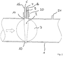
- each ventilation device has a housing 1 with a round flow cross-section, in which a flap leaf 3 is provided that is pivotable about a pivot axis 2 and has two flap surfaces, as well as a device with two measuring points 4, 5 for determining the volume flow of a gaseous one in the housing 1 flowing medium M on.
- the flap leaf 3 has a hollow chamber 6, 7 on each of its two flap surfaces.
- the hollow chamber 6, 7 extends over the entire respective flap surface.
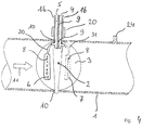
- Fig. 4 an embodiment is shown in which each hollow chamber 6, 7 is elongated and arranged parallel to the pivot axis 2.
- the relevant hollow chamber 6, 7 can be integrated into the valve leaf 3, for example.
- each hollow chamber 6, 7 is placed on the surface of the valve leaf 3 or is arranged at a distance from the surface of the valve leaf 3.
- Each hollow chamber 6, 7 is provided with a multiplicity of removal points 8 designed in the manner of a perforation.
- the extraction points 8 are designed as recesses.
- the valve leaf 3 shows Fig. 1 seen in the side view an approximately lenticular configuration.
- One measuring point 4 is connected to one hollow chamber 6 on one flap surface and the other measuring point 5 is connected to the other hollow chamber 7 on the other flap surface.
- the one in the Figs. 1 to 3 The illustrated embodiment, the pivot axis 2 is designed as a hollow axis.
- a partition wall 9 which extends in the axial direction and which divides the hollow space of the hollow axle into two airtightly separated, preferably equally large, hollow space subregions.
- a variant is shown in which the pivot axis 2 is designed as a hollow axis only in a partial area.
- the one designed as a hollow axle Part of the pivot axis 2 extends from the end protruding from the housing 1 as far as the opposite end of the pivot axis 2 behind the housing opening 10 and thus into the area of the pivot axis 2 that is located inside the housing 1.
- the pivot axis 2 is designed as a hollow axis only in the partial area which extends from the end protruding from the outside of the housing 1 to beyond the adjoining housing opening 10.
- the respective hollow chamber 6, 7 is connected to the respective partial cavity area via lines 30, 31.
- both ends of the pivot axis 2 protrude on the outside of the housing 1 through a housing opening 10 located in the housing 1.
- the hollow axle itself forms both pressure lines in the area of the passage through the housing 1.
- the two measuring points 4, 5 are connected to a transmitter 11.
- the transmitter 11 is plugged directly onto one of the two ends of the pivot axis 2.
- Each measuring point 4, 5 is formed by a removal opening arranged in the area of the face of said end of the pivot axis 2.
- the transmitter 11 has two tubular coupling elements 12, 13 that protrude into the removal openings at the ends in the assembly position.
- an adapter 14 is provided which encompasses said end of the pivot axis 2 and is arranged outside the housing 1.
- the adapter 14 has a recess, designed in the manner of a sleeve 15, for receiving the end of the pivot axis 2.
- the end of the pivot axis 2 has two opposing locking grooves 16, which in the FIG Fig. 3
- the fixing position shown interact with two opposing locking lugs 17 of the adapter 14.
- the recess is at least in the area of the locking lugs 17 in the direction the arrows 29 partially expandable.
- the sleeve 15 in the area of the latching lugs 17, viewed in the axial direction, is designed to be slotted at least in the end area.
- the transmitter 11 is fastened in a rotationally fixed manner to the end of the pivot axis 2.
- the transmitter 11 thus follows the rotary movement of the flap leaf 3.
- a drive 19 connected to the flap leaf 3 via a gear mechanism 18 and arranged outside the housing 1 is provided.
- the end of the pivot axis 2 that interacts with the drive 19 is designed as a toothed ring 20.
- the transmission 18 has an internally toothed wheel 21. During assembly, only the internally toothed wheel 21 has to be slipped onto the end of the pivot axis 2, which is designed as a toothed ring 20.
- the transmitter 11 is connected to a control device 22 which is also arranged on the outside of the housing 1.
- the device has a unit 23 provided on the outside of the housing 1.
- the transmitter 11, the adapter 14, the drive 19, the transmission 18 and the control device 22 are arranged in the unit 23, which is designed as a housing.
- the unit 23 is plugged or clipped onto the housing 1, for example, from the outside.
- a pin-like anti-rotation device 24 is provided which engages in a corresponding recess 25 in the unit 23.
- the unit 23 has an unlocking device 26 for releasing the fixing connection between the adapter 14 and the pivot axis 2.
- the unlocking device 26 is designed as a push button which has a conically tapering surface 27 at the end cooperating with the sleeve 15, so that the end has the shape of a truncated cone. After contact with the sleeve 15, the sleeve 15 is expanded upon further axial displacement of the push button in the direction of the arrow 28 in the area of the locking lugs 17. To release the unit 23 only the push button has to be pressed. This releases the fixing connection and the unit 23 can be removed from the housing 1 without tools.
- the pivot axis 2 is inserted into the flap leaf 3. This allows easy assembly. During assembly, the valve leaf 3 is held in the correct position in the housing 1 and then the pivot axis 2 is inserted from the outside through the housing 1 into the valve leaf 3. To this extent, the flap leaf 3 is arranged in a rotationally fixed manner on the pivot axis 2. Of course, a one-piece arrangement of the flap leaf 3 and pivot axis 2 is also possible. It is also conceivable that the pivot axis 2 is arranged in a rotationally fixed manner in the housing 1 and the flap leaf 3 rotates about the pivot axis 2.
- the transmitter 11 and the control device 22 are connected to one another via a line 32.
- the electrical connection between the control device 22 and the drive 19 is not shown.
- control device 22 and the drive 19 are separate components. It is of course also possible that the regulating device 22 is a component of the drive 19 as an alternative. The control device 22 is then integrated into the drive 19.
Landscapes
- Engineering & Computer Science (AREA)
- Physics & Mathematics (AREA)
- Fluid Mechanics (AREA)
- Chemical & Material Sciences (AREA)
- Combustion & Propulsion (AREA)
- Mechanical Engineering (AREA)
- General Engineering & Computer Science (AREA)
- General Physics & Mathematics (AREA)
- Measuring Fluid Pressure (AREA)
- Air-Flow Control Members (AREA)
Description
- Die Erfindung betrifft eine lufttechnische Einrichtung zur Verwendung in einer klimatechnischen Anlage mit einem, vorzugsweise einen runden oder einen viereckigen Strömungsquerschnitt aufweisenden, Gehäuse, mit einem um eine Schwenkachse schwenkbar gelagerten sowie zwei Klappenflächen aufweisenden Klappenblatt, und mit einer Vorrichtung mit zumindest einer Messstelle zur Bestimmung des Druckes eines gasförmigen, in dem Gehäuse strömenden Mediums M, wobei das Klappenblatt wenigstens eine, vorzugsweise auf zumindest einer Klappenfläche angeordnete, Entnahmestelle aufweist, die mit der Messstelle verbunden ist.
- Entsprechende lufttechnische Einrichtungen sind beispielsweise als Volumenstromregler, die beispielsweise mechanisch selbsttätig arbeitend sind oder die eine regelungstechnische Einheit bestehend aus Transmitter, Antrieb und Regeleinrichtung aufweisen, ausgebildet. Bei bekannten Einrichtungen ist der Transmitter außerhalb des Gehäuses an der Außenseite des Gehäuses ortsfest befestigt oder direkt auf dem Klappenblatt verschraubt. Eine Montage des Transmitters direkt auf dem Klappenblatt macht einen Austausch des Transmitters nahezu unmöglich. Bei einer Verschlauchung gestalten sich Reinigungsarbeiten aufwändiger, da die Schläuche, die die betreffende Hohlkammer mit dem Transmitter verbinden, eine größere Länge aufweisen. Auch können die Schläuche, über die der Transmitter mit den Messstellen des Klappenblattes verbunden ist, bei der Montage vertauscht werden. In dem Gehäuse frei verlegte Schläuche stellen ein Risiko für die Hygiene dar.
- Aus der
EP 2 669 592 A1 ist eine lufttechnische Einrichtung zur Verwendung in einer klimatechnischen Anlage gemäß dem Oberbegriff von Anspruch 1 bekannt. DieWO 01/75374 A1 - Aufgabe der Erfindung ist es, die vorgenannten Nachteile zu vermeiden und eine lufttechnische Einrichtung anzugeben, die beispielweise zu Zwecken der einfacheren Montage und der einfacheren Reinigung konstruktiv einfacher ausgestaltet ist.
- Diese Aufgabe wird durch eine lufttechnische Einrichtung mit den Merkmalen von Anspruch 1 gelöst. Bevorzugte Ausführungsformen sind in den abhängigen Ansprüchen definiert. Erfindungsgemäß ist dabei vorgesehen, dass
entweder zumindest ein Ende der Schwenkachse durch eine in dem Gehäuse befindliche und in der Flucht der Schwenkachse befindliche Gehäuseöffnung von außerhalb des Gehäuses zugänglich ist, wobei zumindest eine Messstelle, vorzugsweise jede Messstelle, mit einem Transmitter verbunden ist, der an dem von außerhalb des Gehäuses zugänglichen Endes der Schwenkachse angeordnet und dass der Transmitter drehfest an dem Ende der Schwenkachse befestigt ist, oder aber zumindest ein Ende der Schwenkachse durch eine in dem Gehäuse befindliche Gehäuseöffnung außenseitig aus dem Gehäuse hinausragt, wobei zumindest eine Messstelle, vorzugsweise jede Messstelle, mit einem Transmitter verbunden ist, der an dem aus dem Gehäuse hinausragenden Ende der Schwenkachse angeordnet und dass der Transmitter drehfest an dem Ende der Schwenkachse befestigt ist. - Die erfindungsgemäße lufttechnische Einrichtung zeichnet sich durch eine hohe Kompaktheit aus, da der Transmitter direkt an dem Ende der Schwenkachse angeordnet ist. Gleichwohl ist eine leichte Trennbarkeit von Transmitter und Schwenkachse gewährleistet, um eine schnelle und einfache Demontage beispielsweise für eine Reinigung durchführen zu können. Die erfindungsgemäße Ausgestaltung erlaubt eine einfache Aufnahme des Druckes in dem Gehäuse oder eines anderen druckäquivalenten Signals. Sofern beispielsweise nur der statische Druck bestimmt werden soll, reicht eine Messstelle aus. Der Transmitter wandelt eine Eingangsgröße nach einer festen Beziehung in eine Ausgangsgröße um. Ein als Drucktransmitter ausgebildeter Transmitter wandelt ein pneumatisches Signal in ein elektrisches Signal um. Insoweit hat ein Drucktransmitter entsprechende pneumatische Anschlüsse für die Messstelle(n) und einen elektrischen Anschluss. Mittels des elektrischen Anschlusses kann der Transmitter beispielsweise an eine Anzeigeeinrichtung oder an eine Regeleinrichtung angeschlossen werden. In einem Transmitter kann - sofern zwei Messstellen vorgesehen sind - der Differenzdruck bestimmt werden. Ein Transmitter kann beispielsweise einen integrierten piezoresistiven Druckaufnehmer, wie beispielsweise eine Monosilikonschicht als Messelement, aufweisen. Bei Druckbeaufschlagung wird die Monosilikonschicht ausgelenkt und generiert ein Spannungssignal. Dieses Spannungssignal kann dann an eine Anzeigeeinrichtung oder an eine Regeleinrichtung weitergeleitet werden. Bei einer Entnahmestelle kann es sich beispielsweise um eine Ausnehmung oder ein Loch handeln. Selbstverständlich sind auch andere geeignete Ausgestaltungen denkbar.
- Zumindest eine Messstelle, vorzugsweise jede Messstelle kann durch eine im Bereich der Stirnseite des besagten Endes der Schwenkachse angeordnete Entnahmeöffnung gebildet sein, und der Transmitter kann zumindest ein, vorzugsweise rohrförmig ausgebildetes und in der Montageposition endseitig in die jeweilige korrespondierende Entnahmeöffnung hineinragendes, Kupplungselement aufweisen. Bei einer solchen Ausgestaltung fungiert das Ende der Schwenkachse als eine Art Steckdose, in die der einem Stecker ähnelnde Transmitter eingeführt wird. Selbstverständlich ist auch eine umgekehrte Anordnung denkbar. So kann der Transmitter beispielsweise zwei Entnahmeöffnungen aufweisen, und jede Messstelle kann im Bereich der Stirnseite des besagten Endes der Schwenkachse zwei, vorzugsweise rohrförmig ausgebildete und in der Montageposition endseitig in die korrespondierende Entnahmeöffnungen hineinragende, Kupplungselemente aufweisen.
- Der Transmitter kann auf das Ende der Schwenkachse aufsteckbar sein. Vorzugsweise ist das Aufstecken und auch ein späteres Lösen werkzeuglos möglich. Die Aufsteckbewegung auf das Ende der Schwenkachse erfolgt beispielsweise in axialer Richtung der Schwenkachse.
- Ferner kann ein das besagte Ende der Schwenkachse umfassender, vorzugsweise außerhalb des Gehäuses angeordneter, Adapter vorgesehen sein.
- Der Adapter kann eine, vorzugsweise nach Art einer Hülse ausgebildete, Ausnehmung zur Aufnahme des Endes der Schwenkachse aufweisen. Zur Fixierung des Adapters gegenüber dem Ende der Schwenkachse kann entweder das Ende der Schwenkachse eine Rastnase aufweisen, die in der Fixierposition mit einer Rastnut in dem Adapter zusammenwirkt, oder aber das Ende der Schwenkachse kann eine Rastnut aufweisen, in die in der Fixierposition ein an dem Adapter vorgesehene Rastnase eingreift.
- Zum Lösen der Fixierverbindung zwischen dem Adapter und der Schwenkachse kann die Ausnehmung zumindest im Bereich der Rastnase/Rastnut teilweise aufweitbar sein. Beim Aufweiten wird die Einrastverbindung zwischen jeder Rastnase und der korrespondierenden Rastnut gelöst, so dass dann der Adapter abgenommen werden kann.
- Die Hülse kann im Bereich der Rastnase/Rastnut in axialer Richtung gesehen wenigstens bereichsweise geschlitzt ausgebildet sein. Die schlitzförmige Ausbildung erleichtert das Aufweiten und damit das Abnehmen des Adapters.
- Der Transmitter ist drehfest an dem Ende der Schwenkachse befestigt. Bei einer solchen Ausgestaltung macht der Transmitter die Drehbewegung der Schwenkachse mit, d. h. der Transmitter dreht mit.
- In einer nicht zur Erfindung gehörenden Alternative kann der Transmitter drehbar gegenüber der Schwenkachse an dem Ende der Schwenkachse angeordnet sein. Bei einer solchen Ausgestaltung bleibt die Ausrichtung des Transmitters gegenüber dem Gehäuse in jeder Stellung des Klappenblattes unverändert. Bei einer solchen Ausgestaltung ist der Transmitter beispielsweise über flexible Druckschläuche mit den Messstellen verbunden.
- Die Schwenkachse kann zumindest in dem Teilbereich, der sich von außerhalb des Gehäuses durch die Gehäuseöffnung nach innerhalb des Gehäuses erstreckt, vorzugsweise zumindest in dem Teilbereich, der sich von dem von außerhalb des Gehäuses zugänglichen Ende bzw. der sich von dem außenseitig aus dem Gehäuse hinausragenden Ende bis jenseits der angrenzenden Gehäuseöffnung erstreckt, als Hohlachse ausgebildet sein. Es ist selbstverständlich auch denkbar, dass die Schwenkachse über die komplette Länge als Hohlachse ausgebildet ist, wobei dann vorzugsweise eines der beiden Enden verschlossen ausgebildet ist.
- Bei einer solchen Ausgestaltung kann die Schwenkachse in dem Bereich, in dem sie als Hohlachse ausgebildet ist, zur Durchführung zumindest einer Druckleitung, vorzugsweise beider Druckleitungen, ausgebildet sein oder aber die Schwenkachse kann in dem Bereich, in dem sie als Hohlachse ausgebildet ist, zumindest eine Druckleitung, vorzugsweise beide Druckleitungen, selber bilden. Sofern die Hohlachse selbst beispielsweise beide Druckleitungen bildet, befindet sich in der Hohlachse eine sich in axialer Richtung erstreckende Trennwandung, die den Hohlraum der Hohlachse in zwei luftdicht voneinander abgetrennte, vorzugsweise gleich große, Hohlraumteilbereiche unterteilt.
- Zum Verschwenken des Klappenblattes kann ein mit dem Klappenblatt mittelbar oder unmittelbar verbundener, vorzugsweise außerhalb des Gehäuses angeordneter, Antrieb vorgesehen sein. Vorzugsweise ist die Verbindung zwischen dem Klappenblatt und dem Antrieb derart, dass der Antrieb bei der Montage nur in einer Position mit dem Klappenblatt verbunden werden kann. In diesem Fall bedarf es keiner Abstimmung mehr zwischen der Stellung des Antriebs und der Stellung des Klappenblattes.
- Das mittelbar bzw. das unmittelbar mit dem Antrieb zusammenwirkende Ende der Schwenkachse kann als Zahnkranz ausgebildet sein. Bei einer solchen Ausgestaltung bietet es sich an, wenn der Antrieb über ein innenverzahntes Rad mit der Schwenkachse verbunden ist. Das innenverzahnte Rad kann beispielsweise Bestandteil eines Getriebes sein. Bei der Montage muss das innenverzahnte Rad lediglich auf das als Zahnkranz ausgebildete Ende der Schwenkachse aufgesteckt werden.
- Das mittelbar bzw. das unmittelbar mit dem Antrieb zusammenwirkende Ende der Schwenkachse kann aber auch eine andere Ausgestaltung, nämlich eine vom Kreis abweichende Form aufweisen, insbesondere als Vierkant ausgebildet sein. Sofern beispielsweise die Schwenkachse über einen Hebel mit dem Antrieb verbunden ist, weist der Hebel eine mit dem Ende der Schwenkachse korrespondierende Ausnehmung auf, in die das Ende der Schwenkachse geführt ist.
- Der Transmitter kann mit einer, vorzugsweise auf der Außenseite des Gehäuses angeordneten, Regeleinrichtung verbunden sein.
- Die Regeleinrichtung kann Bestandteil des Antriebes sein. Dann ist die Regeleinrichtung in den Antrieb integriert. Die Kombination einer in einen Antrieb integrierten Regeleinrichtung wird auch als Kompaktregler bezeichnet. Ein Kompaktregler übernimmt damit die Funktionen sowohl eines Antriebes als auch eines Reglers, d. h. der Regeleinrichtung.
- Die Einrichtung kann eine außenseitig an dem Gehäuse montierbare, vorzugsweise aufsteckbare oder anklipsbare, Einheit aufweisen, in der der Transmitter und/oder der Adapter und/oder der Antrieb und/oder ein zwischen der Schwenkachse und dem Antrieb angeordnetes Getriebe und/oder die Regeleinrichtung angeordnet ist (sind). Sofern die Einheit beispielsweise aufsteckbar oder anklipsbar ist, ist eine werkzeuglose Montage und auch Demontage möglich. Bei der Einheit kann es sich um ein, beispielsweise aus einem Unterteil und aus einem Oberteil bestehendes, Gehäuse handeln, in dem der Transmitter und/oder der Adapter und/oder der Antrieb und/oder ein zwischen der Schwenkachse und dem Antrieb angeordnetes Getriebe und/oder die Regeleinrichtung angeordnet ist (sind). Hierdurch ist beispielsweise eine einfache Montage möglich. So kann zunächst vor Ort das Gehäuse mit dem darin angeordneten Klappenblatt an ein gebäudeseitiges Lüftungssystem angeschlossen werden. Für eine anschließende Inbetriebnahme muss lediglich die Einheit, in der vorzugsweise sämtliche vorgenannten Bauteile bereits werkseitig angebracht und auch bereits untereinander verbunden sind, so dass eine Kommunikation möglich ist, beispielsweise mittels Klipse an der Außenseite des Gehäuses angebracht werden. Damit kann die Einheit leicht von der "Grundeinheit" bestehend aus dem Gehäuse, dem Klappenblatt und der Schwenkachse getrennt werden. Dies ermöglicht z. B. einen einfachen einhändigen Austausch eines Antriebs, oder die Reinigung der Hohlkammern des Klappenblattes über die freigelegten Leitungen der Hohlachse.
- Die Einheit kann eine Entriegelungseinrichtung zum Lösen der Fixierverbindung zwischen dem Adapter und der Schwenkachse aufweisen. Dies ermöglicht eine einfache und schnelle Demontage der Einheit von dem Gehäuse. Durch das Aktivieren der Entriegelungseinrichtung wird die Fixierverbindung zwischen dem Adapter und der Schwenkachse gelöst, so dass die Einheit abgenommen werden kann.
- Die Entriegelungseinrichtung kann als Drückknopf, der an dem mit der Hülse zusammenwirkenden Ende zumindest eine konisch zulaufende Fläche aufweist, ausgebildet sein, so dass bei Kontakt mit der Hülse die Hülse bei weiterer axialer Verlagerung des Drückknopfes im Bereich der Rastnase/Rastnut zumindest teilweise aufgeweitet wird. Das mit der Hülse zusammenwirkende Ende des Drückknopfes kann beispielsweise als Kegelstumpf ausgebildet sein. Der Drückknopf ist vorzugsweise von außerhalb der Einheit zugänglich, so dass ohne ein Öffnen der Einheit eine Montage und eine Demontage der Einheit von dem Gehäuse möglich ist.
- Es bietet sich an, wenn innerhalb und/oder außerhalb des Gehäuses ein mit dem Klappenblatt und/oder mit der Schwenkachse mittelbar oder unmittelbar verbundenes und sich entsprechend der Bewegung des Klappenblattes ebenfalls bewegendes Anzeigeelement vorgesehen ist, welches zur Sichtkontrolle der Stellung des Klappenblattes von außerhalb des Gehäuses frei sichtbar angeordnet ist. Damit kann aufgrund der von außen ablesbaren Stellung des Anzeigeelementes auf die Stellung des Klappenblattes geschlossen werden, auch wenn das Klappenblatt selbst von außerhalb des Gehäuses nicht sichtbar ist.
- Das Anzeigeelement kann beispielsweise als, insbesondere auf der Entriegelungseinrichtung angebrachte, Markierung ausgebildet sein. Bei der Markierung kann es sich beispielsweise um eine Einkerbung in einem Bauteil handeln, das mit dem Klappenblatt mitdreht und von außen sichtbar ist.
- Dabei können zwei Messstellen zur Bestimmung des Volumenstroms eines gasförmigen, in dem Gehäuse strömenden Mediums M vorgesehen sein, wobei das Klappenblatt auf seinen beiden Klappenflächen jeweils zumindest eine Hohlkammer aufweist, wobei jede Hohlkammer mit zumindest einer Entnahmestelle, vorzugsweise mit einer Vielzahl an nach Art einer Perforation ausgebildeten Entnahmestellen, versehen ist und wobei die eine Messstelle mit der einen Hohlkammer auf der einen Klappenfläche und die andere Messstelle mit der anderen Hohlkammer auf der anderen Klappenfläche verbunden sind. Bei er solchen Ausgestaltung ermöglicht die lufttechnische Einrichtung auch bei sehr geringen Volumenströmen die Bestimmung eines hohen Differenzdruckes und damit eine hinreichende Regelgenauigkeit.
- Im Folgenden werden in den Zeichnungen dargestellte Ausführungsbeispiele der Erfindung erläutert. Es zeigen:
- Fig. 1
- einen Schnitt durch eine lufttechnische Einrichtung mit einem stark vereinfacht dargestellten Transmitter,
- Fig. 2
- einen Schnitt durch eine lufttechnische Einrichtung ohne einen Transmitter und ohne einen Antrieb,
- Fig. 3
- einen Schnitt durch eine alternative Ausgestaltung einer lufttechnischen Einrichtung und
- Fig. 4
- einen Schnitt durch eine alternative Ausgestaltung einer lufttechnischen Einrichtung.
- In allen Figuren werden für gleiche bzw. gleichartige Bauteile übereinstimmende Bezugszeichen verwendet.
- Die
Fig. 1 bis 4 zeigen drei Ausgestaltungen einer lufttechnischen Einrichtung zur Verwendung in einer klimatechnischen Anlage. Jede lufttechnische Einrichtung weist ein einen runden Strömungsquerschnitt aufweisendes Gehäuse 1, in dem ein um eine Schwenkachse 2 schwenkbar gelagertes sowie zwei Klappenflächen aufweisendes Klappenblatt 3 vorgesehen ist, sowie eine Vorrichtung mit zwei Messstellen 4, 5 zur Bestimmung des Volumenstroms eines gasförmigen, in dem Gehäuse 1 strömenden Mediums M auf. - Das Klappenblatt 3 weist auf seinen beiden Klappenflächen jeweils eine Hohlkammer 6, 7 auf. Bei dem Ausführungsbeispiel nach
Fig. 1 erstreckt sich die Hohlkammer 6, 7 über die komplette jeweilige Klappenfläche. InFig. 4 ist eine Ausgestaltung dargestellt, bei dem jede Hohlkammer 6, 7 länglich ausgebildet und parallel zur Schwenkachse 2 angeordnet ist. Die betreffende Hohlkammer 6, 7 kann beispielsweise in dem Klappenblatt 3 integriert sein. Es ist aber auch durchaus möglich, dass jede Hohlkammer 6, 7 auf die Oberfläche des Klappenblattes 3 aufgesetzt oder in einem Abstand zu der Oberfläche des Klappenblattes 3 angeordnet ist. - Jede Hohlkammer 6, 7 ist mit einer Vielzahl an nach Art einer Perforation ausgebildeten Entnahmestellen 8 versehen. In
Fig. 1 sind die Entnahmestellen 8 als Ausnehmungen ausgebildet. Wie den Figuren zu entnehmen ist, weist das Klappenblatt 3 nachFig. 1 in der Seitenansicht gesehen eine in etwa linsenförmige Ausgestaltung auf. - Die eine Messstelle 4 ist mit der einen Hohlkammer 6 auf der einen Klappenfläche und die andere Messstelle 5 mit der anderen Hohlkammer 7 auf der anderen Klappenfläche verbunden. Bei dem in den
Fig. 1 bis 3 dargestellten Ausführungsbeispiel ist die Schwenkachse 2 als Hohlachse ausgebildet. In der Hohlachse befindet sich eine in axialer Richtung erstreckende Trennwandung 9, die den Hohlraum der Hohlachse in zwei luftdicht voneinander abgetrennte, vorzugsweise gleich große, Hohlraumteilbereiche unterteilt. - In
Fig. 4 ist eine Variante dargestellt, bei der die Schwenkachse 2 nur in einem Teilbereich als Hohlachse ausgebildet ist. Der als Hohlachse ausgebildete Teilbereich der Schwenkachse 2 erstreckt sich von dem aus dem Gehäuse 1 hinausragenden Ende gesehen bis in Richtung des gegenüberliegenden Endes der Schwenkachse 2 gesehen hinter die Gehäuseöffnung 10 und damit in den Bereich der Schwenkachse 2, der sich innerhalb des Gehäuses 1 befindet. Damit ist bei der Ausgestaltung nachFig. 4 die Schwenkachse 2 lediglich in dem Teilbereich, der sich von dem außenseitig aus dem Gehäuse 1 hinausragenden Ende bis jenseits der angrenzenden Gehäuseöffnung 10 erstreckt, als Hohlachse ausgebildet ist. Über Leitungen 30, 31 ist die jeweilige Hohlkammer 6, 7 mit dem jeweiligen Hohlraumteilbereich verbunden. - Bei den in den
Fig. 1 bis 4 dargestellten Ausführungsbeispielen ragen beide Enden der Schwenkachse 2 durch jeweils eine in dem Gehäuse 1 befindliche Gehäuseöffnung 10 außenseitig aus dem Gehäuse 1 hinaus. In allen dargestellten Ausführungsbeispielen bildet die Hohlachse im Bereich des Durchgangs durch das Gehäuse 1 beide Druckleitungen selber. Die beiden Messstellen 4, 5 sind mit einem Transmitter 11 verbunden. Der Transmitter 11 ist dabei direkt auf eines der beiden Enden der Schwenkachse 2 aufgesteckt. Jede Messstelle 4, 5 wird durch eine im Bereich der Stirnseite des besagten Endes der Schwenkachse 2 angeordnete Entnahmeöffnung gebildet. Der Transmitter 11 weist zwei, rohrförmig ausgebildete und in der Montageposition endseitig in die Entnahmeöffnungen hineinragende Kupplungselemente 12, 13 auf. - In den
Fig. 2 bis 4 ist eine Ausgestaltung dargestellt, bei dem ein das besagte Ende der Schwenkachse 2 umfassender und außerhalb des Gehäuses 1 angeordneter Adapter 14 vorgesehen ist. Der Adapter 14 weist eine, nach Art einer Hülse 15 ausgebildete, Ausnehmung zur Aufnahme des Endes der Schwenkachse 2 auf. Zur Fixierung des Adapters 14 gegenüber dem Ende der Schwenkachse 2 weist das Ende der Schwenkachse 2 zwei gegenüberliegende Rastnuten 16 auf, die in der inFig. 3 dargestellten Fixierposition mit zwei gegenüberliegenden Rastnasen 17 des Adapters 14 zusammenwirken. - Zum Lösen der Fixierverbindung zwischen dem Adapter 14 und der Schwenkachse 2 ist die Ausnehmung zumindest im Bereich der Rastnasen 17 in Richtung der Pfeile 29 teilweise aufweitbar. Hierzu ist die Hülse 15 im Bereich der Rastnasen 17 in axialer Richtung gesehen zumindest im Endbereich geschlitzt ausgebildet.
- Bei dem dargestellten Ausführungsbeispiel ist der Transmitter 11 drehfest an dem Ende der Schwenkachse 2 befestigt. Damit macht der Transmitter 11 die Drehbewegung des Klappenblattes 3 mit.
- Zum Verschwenken des Klappenblattes 3 ist ein über ein Getriebe 18 mit dem Klappenblatt 3 verbundener und außerhalb des Gehäuses 1 angeordneter Antrieb 19 vorgesehen. Das mit dem Antrieb 19 zusammenwirkende Ende der Schwenkachse 2 ist als Zahnkranz 20 ausgebildet. Das Getriebe 18 weist ein innenverzahntes Rad 21 auf. Bei der Montage muss lediglich das innenverzahnte Rad 21 auf das als Zahnkranz 20 ausgebildete Ende der Schwenkachse 2 aufgesteckt werden. Der Transmitter 11 ist mit einer, ebenfalls auf der Außenseite des Gehäuses 1 angeordneten, Regeleinrichtung 22 verbunden.
- Wie
Fig. 3 zu entnehmen ist, weist die Einrichtung eine außenseitig an dem Gehäuse 1 vorgesehene Einheit 23 auf. In der als Gehäuse ausgebildeten Einheit 23 ist der Transmitter 11, der Adapter 14, der Antrieb 19, das Getriebe 18 und die Regeleinrichtung 22 angeordnet. Die Einheit 23 ist beispielsweise von außen auf das Gehäuse 1 aufgesteckt oder angeklipst. Um ein Verdrehen der Einheit 23 gegenüber dem Gehäuse 1 zu verhindern, ist eine stiftartige Verdrehsicherung 24 vorgesehen, die in eine entsprechende Ausnehmung 25 in der Einheit 23 eingreift. - Zusätzlich weist die Einheit 23 eine Entriegelungseinrichtung 26 zum Lösen der Fixierverbindung zwischen dem Adapter 14 und der Schwenkachse 2 auf. Die Entriegelungseinrichtung 26 ist als Drückknopf ausgebildet, der an dem mit der Hülse 15 zusammenwirkenden Ende eine konisch zulaufende Fläche 27 aufweist, so dass das Ende die Form eines Kegelstumpfes hat. Nach Kontakt mit der Hülse 15 wird die Hülse 15 bei weiterer axialer Verlagerung des Drüccknopfes in Richtung des Pfeils 28 im Bereich der Rastnasen 17 aufgeweitet. Zum Lösen der Einheit 23 muss lediglich der Drückknopf gedrückt werden. Hierdurch löst sich die Fixierverbindung und die Einheit 23 kann vom Gehäuse 1 werkzeuglos entfernt werden.
- In den dargestellten Ausführungsbeispielen ist die Schwenkachse 2 in das Klappenblatt 3 eingesteckt. Dies erlaubt eine einfache Montage. Bei der Montage wird das Klappenblatt 3 in dem Gehäuse 1 in der richtigen Position gehalten und anschließend von außen die Schwenkachse 2 durch das Gehäuse 1 in das Klappenblatt 3 gesteckt. Das Klappenblatt 3 ist insoweit drehfest auf der Schwenkachse 2 angeordnet. Selbstverständlich ist auch eine einteilige Anordnung von Klappenblatt 3 und Schwenkachse 2 möglich. Auch ist es denkbar, dass die Schwenkachse 2 drehfest in dem Gehäuse 1 angeordnet ist und das Klappenblatt 3 um die Schwenkachse 2 dreht.
- Bei dem beispielsweise in
Fig. 3 dargestellten Ausführungsbeispiel sind der Transmitter 11 und die Regeleinrichtung 22 über eine Leitung 32 miteinander verbunden. Die elektrische Verbindung zwischen der Regeleinrichtung 22 und dem Antrieb 19 ist nicht dargestellt. - In dem dargestellten Ausführungsbeispiel handelt es sich bei der Regeleinrichtung 22 und bei dem Antrieb 19 um separate Bauteile. Selbstverständlich ist es auch möglich, dass alternativ die Regeleinrichtung 22 Bestandteil des Antriebes 19 ist. Dann ist die Regeleinrichtung 22 in den Antrieb 19 integriert.
Claims (23)
- Lufttechnische Einrichtung zur Verwendung in einer klimatechnischen Anlage mit einem, vorzugsweise einen runden oder einen viereckigen Strömungsquerschnitt aufweisenden, Gehäuse (1), mit einem um eine Schwenkachse (2) schwenkbar gelagerten sowie zwei Klappenflächen aufweisenden Klappenblatt (3), und mit einer Vorrichtung mit zumindest einer Messstelle (4, 5) zur Bestimmung des Druckes eines gasförmigen, in dem Gehäuse (1) strömenden Mediums M, wobei das Klappenblatt (3) wenigstens eine, vorzugsweise auf zumindest einer Klappenfläche angeordnete, Entnahmestelle (8) aufweist, die mit einer der zumindest einen Messstelle (4, 5) verbunden ist, dadurch gekennzeichnet, dass
entweder zumindest ein Ende der Schwenkachse (2) durch eine in dem Gehäuse (1) befindliche und in der Flucht der Schwenkachse (2) befindliche Gehäuseöffnung (10) von außerhalb des Gehäuses (1) zugänglich ist, wobei zumindest eine Messstelle (4, 5), vorzugsweise jede Messstelle (4, 5), mit einem Transmitter (11) verbunden ist, der an dem von außerhalb des Gehäuses (1) zugänglichen Endes der Schwenkachse (2) angeordnet und dass der Transmitter (11) drehfest an dem Ende der Schwenkachse (2) befestigt ist, oder aber zumindest ein Ende der Schwenkachse (2) durch eine in dem Gehäuse (1) befindliche Gehäuseöffnung (10) außenseitig aus dem Gehäuse (1) hinausragt, wobei zumindest eine Messstelle (4, 5), vorzugsweise jede Messstelle (4, 5), mit einem Transmitter (11) verbunden ist, der an dem aus dem Gehäuse (1) hinausragenden Ende der Schwenkachse (2) angeordnet und dass der Transmitter (11) drehfest an dem Ende der Schwenkachse (2) befestigt ist. - Lufttechnische Einrichtung nach dem vorhergehenden Anspruch, dadurch gekennzeichnet, dass zumindest eine Messstelle (4, 5), vorzugsweise jede Messstelle (4, 5) durch eine im Bereich der Stirnseite des besagten Endes der Schwenkachse (2) angeordnete Entnahmeöffnung gebildet ist und dass der Transmitter (11) zumindest ein, vorzugsweise rohrförmig ausgebildetes und in der Montageposition endseitig in die jeweilige korrespondierende Entnahmeöffnung hineinragendes, Kupplungselement (12 bzw. 13) aufweist.
- Lufttechnische Einrichtung nach einem der vorhergehenden Ansprüche, dadurch gekennzeichnet, dass der Transmitter (11) auf das Ende der Schwenkachse (2) aufsteckbar ist.
- Lufttechnische Einrichtung nach einem der vorhergehenden Ansprüche, dadurch gekennzeichnet, dass ein das besagte Ende der Schwenkachse (2) umfassender, vorzugsweise außerhalb des Gehäuses (1) angeordneter, Adapter (14) vorgesehen ist.
- Lufttechnische Einrichtung nach dem vorhergehenden Anspruch, dadurch gekennzeichnet, dass der Adapter (14) eine, vorzugsweise nach Art einer Hülse (15) ausgebildete, Ausnehmung zur Aufnahme des Endes der Schwenkachse (2) aufweist und dass zur Fixierung des Adapters (14) gegenüber dem Ende entweder das Ende der Schwenkachse (2) eine Rastnase (17) aufweist, die in der Fixierposition mit einer Rastnut (16) in dem Adapter (14) zusammenwirkt, oder aber dass das Ende der Schwenkachse (2) eine Rastnut (16) aufweist, in die in der Fixierposition ein an dem Adapter (14) vorgesehene Rastnase (17) eingreift.
- Lufttechnische Einrichtung nach dem vorhergehenden Anspruch, dadurch gekennzeichnet, dass zum Lösen der Fixierverbindung zwischen dem Adapter (14) und der Schwenkachse (2) die Ausnehmung zumindest im Bereich der Rastnase/Rastnut (17, 16) teilweise aufweitbar ist.
- Lufttechnische Einrichtung nach einem der Ansprüche 5 oder 6, dadurch gekennzeichnet, dass die Hülse (15) im Bereich der Rastnase/Rastnut (17, 16) in axialer Richtung gesehen wenigstens bereichsweise geschlitzt ausgebildet ist.
- Lufttechnische Einrichtung nach einem der vorhergehenden Ansprüche, dadurch gekennzeichnet, dass die Schwenkachse (2) zumindest in dem Teilbereich, der sich von außerhalb des Gehäuses (1) durch die Gehäuseöffnung (10) nach innerhalb des Gehäuses (1) erstreckt, vorzugsweise zumindest in dem Teilbereich, der sich von dem von außerhalb des Gehäuses (1) zugänglichen Ende bzw. der sich von dem außenseitig aus dem Gehäuse (1) hinausragenden Ende bis jenseits der angrenzenden Gehäuseöffnung (10) erstreckt, als Hohlachse ausgebildet ist.
- Lufttechnische Einrichtung nach dem vorhergehenden Anspruch, dadurch gekennzeichnet, dass die Schwenkachse (2) in dem Bereich, in dem sie als Hohlachse ausgebildet ist, zur Durchführung zumindest einer Druckleitung, vorzugsweise beider Druckleitungen, ausgebildet ist oder aber dass die Schwenkachse (2) in dem Bereich, in dem sie als Hohlachse ausgebildet ist, zumindest eine Druckleitung, vorzugsweise beide Druckleitungen, selber bildet.
- Lufttechnische Einrichtung nach einem der vorhergehenden Ansprüche, dadurch gekennzeichnet, dass zum Verschwenken des Klappenblattes (3) ein mit dem Klappenblatt (3) mittelbar oder unmittelbar verbundener, vorzugsweise außerhalb des Gehäuses (1) angeordneter, Antrieb (19) vorgesehen ist.
- Lufttechnische Einrichtung nach dem vorhergehenden Anspruch, dadurch gekennzeichnet, dass das mittelbar bzw. das unmittelbar mit dem Antrieb (19) zusammenwirkende Ende der Schwenkachse (2) als Zahnkranz (20) ausgebildet ist.
- Lufttechnische Einrichtung nach Anspruch 10, dadurch gekennzeichnet, dass das mittelbar bzw. das unmittelbar mit dem Antrieb (19) zusammenwirkende Ende der Schwenkachse (2) eine vom Kreis abweichende Form aufweist, insbesondere als Vierkant ausgebildet ist.
- Lufttechnische Einrichtung nach einem der vorhergehenden Ansprüche, dadurch gekennzeichnet, dass der Transmitter (11) mit einer, vorzugsweise auf der Außenseite des Gehäuses (1) angeordneten, Regeleinrichtung (22) verbunden ist.
- Lufttechnische Einrichtung nach dem vorhergehenden Anspruch, soweit dieser auf einen der Ansprüche 10 bis 12 rückbezogen ist, dadurch gekennzeichnet, dass die Regeleinrichtung (22) Bestandteil des Antriebes (19) ist.
- Lufttechnische Einrichtung nach einem der vorhergehenden Ansprüche, dadurch gekennzeichnet, dass die Einrichtung eine außenseitig an dem Gehäuse (1) montierbare, vorzugsweise aufsteckbare oder anklipsbare, Einheit (23) aufweist, in der der Transmitter (11) angeordnet ist.
- Lufttechnische Einrichtung nach einem der vorhergehenden Ansprüche, soweit auf Anspruch 4 rückbezogen, dadurch gekennzeichnet, dass die Einrichtung eine außenseitig an dem Gehäuse (1) montierbare, vorzugsweise aufsteckbare oder anklipsbare, Einheit (23) aufweist, in der der Adapter (14) angeordnet ist.
- Lufttechnische Einrichtung nach einem der vorhergehenden Ansprüche, soweit auf Anspruch 10 rückbezogen, dadurch gekennzeichnet, dass die Einrichtung eine außenseitig an dem Gehäuse (1) montierbare, vorzugsweise aufsteckbare oder anklipsbare, Einheit (23) aufweist, in der der Antrieb (19) und/oder ein zwischen der Schwenkachse (2) und dem Antrieb (19) angeordnetes Getriebe (18) angeordnet ist (sind).
- Lufttechnische Einrichtung nach einem der vorhergehenden Ansprüche, soweit auf Anspruch 13 rückbezogen, dadurch gekennzeichnet, dass die Einrichtung eine außenseitig an dem Gehäuse (1) montierbare, vorzugsweise aufsteckbare oder anklipsbare, Einheit (23) aufweist, in der die Regeleinrichtung (22) angeordnet ist.
- Lufttechnische Einrichtung nach einem der Ansprüche 15 bis 18, dadurch gekennzeichnet, dass die Einheit (23) eine Entriegelungseinrichtung (26) zum Lösen der Fixierverbindung zwischen dem Adapter (14) und der Schwenkachse (2) aufweist.
- Lufttechnische Einrichtung nach dem vorhergehenden Anspruch, soweit dieser auf Anspruch 6 rückbezogen ist, dadurch gekennzeichnet, dass die Entriegelungseinrichtung (26) als Drückknopf, der an dem mit der Hülse (15) zusammenwirkenden Ende zumindest eine konisch zulaufende Fläche (27) aufweist, ausgebildet ist, so dass bei Kontakt mit der Hülse (15) die Hülse (15) bei weiterer axialer Verlagerung des Drückknopfes im Bereich der Rastnase/Rastnut (17, 16) zumindest teilweise aufgeweitet wird.
- Lufttechnische Einrichtung nach einem der vorhergehenden Ansprüche, dadurch gekennzeichnet, dass innerhalb und/oder außerhalb des Gehäuses (1) ein mit dem Klappenblatt (3) und/oder mit der Schwenkachse (2) mittelbar oder unmittelbar verbundenes und sich entsprechend der Bewegung des Klappenblattes (3) ebenfalls bewegendes Anzeigeelement vorgesehen ist, welches zur Sichtkontrolle der Stellung des Klappenblattes (3) von außerhalb des Gehäuses (1) frei sichtbar angeordnet ist.
- Lufttechnische Einrichtung nach dem vorhergehenden Anspruch, dadurch gekennzeichnet, dass das Anzeigeelement als, insbesondere auf der Entriegelungseinrichtung (26) angebrachte, Markierung ausgebildet ist.
- Lufttechnische Einrichtung nach einem der vorhergehenden Ansprüche, dadurch gekennzeichnet, dass zwei Messstellen (4, 5) zur Bestimmung des Volumenstroms eines gasförmigen, in dem Gehäuse (1) strömenden Mediums M vorgesehen sind, wobei das Klappenblatt (3) auf seinen beiden Klappenflächen jeweils zumindest eine Hohlkammer (6, 7) aufweist, wobei jede Hohlkammer (6, 7) mit zumindest einer Entnahmestelle (8), vorzugsweise mit einer Vielzahl an nach Art einer Perforation ausgebildeten Entnahmestellen (8), versehen ist und wobei die eine Messstelle (4) mit der einen Hohlkammer (6) auf der einen Klappenfläche und die andere Messstelle (5) mit der anderen Hohlkammer (7) auf der anderen Klappenfläche verbunden sind.
Priority Applications (1)
| Application Number | Priority Date | Filing Date | Title |
|---|---|---|---|
| PL19158539T PL3531037T3 (pl) | 2018-02-23 | 2019-02-21 | Urządzenie wentylacyjne do zastosowania w instalacji klimatyzacyjnej |
Applications Claiming Priority (1)
| Application Number | Priority Date | Filing Date | Title |
|---|---|---|---|
| DE202018101015.8U DE202018101015U1 (de) | 2018-02-23 | 2018-02-23 | Lufttechnische Einrichtung zur Verwendung in einer klimatechnischen Anlage |
Publications (2)
| Publication Number | Publication Date |
|---|---|
| EP3531037A1 EP3531037A1 (de) | 2019-08-28 |
| EP3531037B1 true EP3531037B1 (de) | 2021-11-24 |
Family
ID=62069279
Family Applications (1)
| Application Number | Title | Priority Date | Filing Date |
|---|---|---|---|
| EP19158539.7A Active EP3531037B1 (de) | 2018-02-23 | 2019-02-21 | Lufttechnische einrichtung zur verwendung in einer klimatechnischen anlage |
Country Status (7)
| Country | Link |
|---|---|
| EP (1) | EP3531037B1 (de) |
| DE (1) | DE202018101015U1 (de) |
| DK (1) | DK3531037T3 (de) |
| ES (1) | ES2905966T3 (de) |
| HU (1) | HUE057548T2 (de) |
| PL (1) | PL3531037T3 (de) |
| PT (1) | PT3531037T (de) |
Cited By (1)
| Publication number | Priority date | Publication date | Assignee | Title |
|---|---|---|---|---|
| WO2025036969A1 (en) | 2023-08-15 | 2025-02-20 | Belimo Holding Ag | Drive unit for a damper to control a flow of gas in a duct |
Families Citing this family (1)
| Publication number | Priority date | Publication date | Assignee | Title |
|---|---|---|---|---|
| DE202018102853U1 (de) * | 2018-05-22 | 2019-08-27 | Trox Gmbh | Durchlass einer klimatechnischen Anlage zur Be- und/oder zur Entlüftung von Räumen |
Family Cites Families (3)
| Publication number | Priority date | Publication date | Assignee | Title |
|---|---|---|---|---|
| WO2001075374A1 (en) * | 2000-04-04 | 2001-10-11 | Federspiel Clifford C | Pressure based flow rate measurement device integrated with blades of a damper |
| PL1980798T3 (pl) * | 2007-04-12 | 2011-07-29 | Werner Wildeboer | Regulator przepływu objętościowego wyposażony w czujnik siły |
| ES2566785T5 (es) * | 2012-05-31 | 2019-04-23 | Trox Gmbh Geb | Válvula para su disposición en un conducto de flujo de una instalación de climatización |
-
2018
- 2018-02-23 DE DE202018101015.8U patent/DE202018101015U1/de active Active
-
2019
- 2019-02-21 EP EP19158539.7A patent/EP3531037B1/de active Active
- 2019-02-21 HU HUE19158539A patent/HUE057548T2/hu unknown
- 2019-02-21 DK DK19158539.7T patent/DK3531037T3/da active
- 2019-02-21 ES ES19158539T patent/ES2905966T3/es active Active
- 2019-02-21 PL PL19158539T patent/PL3531037T3/pl unknown
- 2019-02-21 PT PT191585397T patent/PT3531037T/pt unknown
Non-Patent Citations (1)
| Title |
|---|
| None * |
Cited By (1)
| Publication number | Priority date | Publication date | Assignee | Title |
|---|---|---|---|---|
| WO2025036969A1 (en) | 2023-08-15 | 2025-02-20 | Belimo Holding Ag | Drive unit for a damper to control a flow of gas in a duct |
Also Published As
| Publication number | Publication date |
|---|---|
| DE202018101015U1 (de) | 2018-04-18 |
| EP3531037A1 (de) | 2019-08-28 |
| HUE057548T2 (hu) | 2022-05-28 |
| ES2905966T3 (es) | 2022-04-12 |
| PT3531037T (pt) | 2022-02-15 |
| PL3531037T3 (pl) | 2022-04-04 |
| DK3531037T3 (da) | 2022-02-07 |
Similar Documents
| Publication | Publication Date | Title |
|---|---|---|
| EP3492287B1 (de) | Vorrichtung für das messen des drucks eines zweiradreifens, insbesondere eines fahrradreifens | |
| DE202014011108U1 (de) | Dichtstrompumpe und Komponenten | |
| EP3388265B1 (de) | Luftausströmer mit einem reibelement | |
| EP2275786A1 (de) | Vorrichtung zur Bereitstellung von konditionierten Fluidströmungen | |
| DE102014218840A1 (de) | Ausströmer | |
| DE4401787A1 (de) | Strömungsmesserbaugruppe | |
| DE102012015519A1 (de) | Luftleitvorrichtung für eine Luftausströmvorrichtung eines Fahrzeugs | |
| DE20305230U1 (de) | Durchfluss-Messvorrichtung | |
| DE2133422C3 (de) | Mehrstufiges Druckreduzierventil | |
| EP3531037A1 (de) | Lufttechnische einrichtung zur verwendung in einer klimatechnischen anlage | |
| EP1817762B1 (de) | Vorrichtung zum prüfen von anästhesie- und beatmungsgeräten | |
| DE102020207151A1 (de) | Luftausströmer für ein Kraftfahrzeug | |
| DE202017102703U1 (de) | Gehäuseaufbau eines Durchflusssensors | |
| DE102007001052A1 (de) | Blendensystem zur Verwendung in einer Klimaanlage, insbesondere einer Flugzeugklimaanlage | |
| EP1637371A2 (de) | Luftausströmer, insbesondere für ein Fahrzeug | |
| EP0943901B1 (de) | Armatur zur hydraulischen Durchflussmessung | |
| EP3124298A1 (de) | Belüftungseinrichtung | |
| DE102019123149B4 (de) | Staubfilterbeutel | |
| DE102012215686A1 (de) | Luftausströmer | |
| EP2241864A2 (de) | Vorrichtung zur Messung des Volumens- oder Messestromes eines Mediums mittels Differenzdrucksensors mit einer Verbindungsvorrichtung für den Sensor | |
| DE102004059926B3 (de) | Rückschlagventil mit unterschiedlichen Flussrichtungen | |
| DE20217571U1 (de) | Sensor zur Erfassung von Differenzdrücken | |
| DE3342797T1 (de) | Meßeinheit zur Messung des Gasdurchsatzes durch eine Leitung und in eine solche Meßeinheit einbaubare Meßvorrichtung | |
| DE202018101173U1 (de) | Abströmhülse für eine Durchflussmesseinrichtung sowie Durchflussmesseinrichtung | |
| EP3572739B1 (de) | Durchlass einer klimatechnischen anlage zur be- und/oder zur entlüftung von räumen |
Legal Events
| Date | Code | Title | Description |
|---|---|---|---|
| PUAI | Public reference made under article 153(3) epc to a published international application that has entered the european phase |
Free format text: ORIGINAL CODE: 0009012 |
|
| STAA | Information on the status of an ep patent application or granted ep patent |
Free format text: STATUS: THE APPLICATION HAS BEEN PUBLISHED |
|
| AK | Designated contracting states |
Kind code of ref document: A1 Designated state(s): AL AT BE BG CH CY CZ DE DK EE ES FI FR GB GR HR HU IE IS IT LI LT LU LV MC MK MT NL NO PL PT RO RS SE SI SK SM TR |
|
| AX | Request for extension of the european patent |
Extension state: BA ME |
|
| STAA | Information on the status of an ep patent application or granted ep patent |
Free format text: STATUS: REQUEST FOR EXAMINATION WAS MADE |
|
| 17P | Request for examination filed |
Effective date: 20200227 |
|
| RBV | Designated contracting states (corrected) |
Designated state(s): AL AT BE BG CH CY CZ DE DK EE ES FI FR GB GR HR HU IE IS IT LI LT LU LV MC MK MT NL NO PL PT RO RS SE SI SK SM TR |
|
| GRAP | Despatch of communication of intention to grant a patent |
Free format text: ORIGINAL CODE: EPIDOSNIGR1 |
|
| STAA | Information on the status of an ep patent application or granted ep patent |
Free format text: STATUS: GRANT OF PATENT IS INTENDED |
|
| RIC1 | Information provided on ipc code assigned before grant |
Ipc: F24F 13/14 20060101AFI20200630BHEP Ipc: F24F 110/40 20180101ALI20200630BHEP Ipc: F24F 11/74 20180101ALI20200630BHEP Ipc: G01F 1/46 20060101ALI20200630BHEP Ipc: G01F 1/40 20060101ALI20200630BHEP |
|
| INTG | Intention to grant announced |
Effective date: 20200731 |
|
| GRAJ | Information related to disapproval of communication of intention to grant by the applicant or resumption of examination proceedings by the epo deleted |
Free format text: ORIGINAL CODE: EPIDOSDIGR1 |
|
| STAA | Information on the status of an ep patent application or granted ep patent |
Free format text: STATUS: REQUEST FOR EXAMINATION WAS MADE |
|
| GRAS | Grant fee paid |
Free format text: ORIGINAL CODE: EPIDOSNIGR3 |
|
| STAA | Information on the status of an ep patent application or granted ep patent |
Free format text: STATUS: GRANT OF PATENT IS INTENDED |
|
| INTC | Intention to grant announced (deleted) | ||
| GRAP | Despatch of communication of intention to grant a patent |
Free format text: ORIGINAL CODE: EPIDOSNIGR1 |
|
| INTG | Intention to grant announced |
Effective date: 20210114 |
|
| GRAJ | Information related to disapproval of communication of intention to grant by the applicant or resumption of examination proceedings by the epo deleted |
Free format text: ORIGINAL CODE: EPIDOSDIGR1 |
|
| GRAL | Information related to payment of fee for publishing/printing deleted |
Free format text: ORIGINAL CODE: EPIDOSDIGR3 |
|
| STAA | Information on the status of an ep patent application or granted ep patent |
Free format text: STATUS: REQUEST FOR EXAMINATION WAS MADE |
|
| INTC | Intention to grant announced (deleted) | ||
| GRAP | Despatch of communication of intention to grant a patent |
Free format text: ORIGINAL CODE: EPIDOSNIGR1 |
|
| STAA | Information on the status of an ep patent application or granted ep patent |
Free format text: STATUS: GRANT OF PATENT IS INTENDED |
|
| INTG | Intention to grant announced |
Effective date: 20210630 |
|
| RIN1 | Information on inventor provided before grant (corrected) |
Inventor name: LEITNER, DANIEL Inventor name: STEINHAUSEN, HANNAH |
|
| GRAA | (expected) grant |
Free format text: ORIGINAL CODE: 0009210 |
|
| STAA | Information on the status of an ep patent application or granted ep patent |
Free format text: STATUS: THE PATENT HAS BEEN GRANTED |
|
| AK | Designated contracting states |
Kind code of ref document: B1 Designated state(s): AL AT BE BG CH CY CZ DE DK EE ES FI FR GB GR HR HU IE IS IT LI LT LU LV MC MK MT NL NO PL PT RO RS SE SI SK SM TR |
|
| REG | Reference to a national code |
Ref country code: GB Ref legal event code: FG4D Free format text: NOT ENGLISH |
|
| REG | Reference to a national code |
Ref country code: AT Ref legal event code: REF Ref document number: 1450148 Country of ref document: AT Kind code of ref document: T Effective date: 20211215 |
|
| REG | Reference to a national code |
Ref country code: DE Ref legal event code: R096 Ref document number: 502019002801 Country of ref document: DE |
|
| REG | Reference to a national code |
Ref country code: IE Ref legal event code: FG4D Free format text: LANGUAGE OF EP DOCUMENT: GERMAN |
|
| REG | Reference to a national code |
Ref country code: DK Ref legal event code: T3 Effective date: 20220131 |
|
| REG | Reference to a national code |
Ref country code: PT Ref legal event code: SC4A Ref document number: 3531037 Country of ref document: PT Date of ref document: 20220215 Kind code of ref document: T Free format text: AVAILABILITY OF NATIONAL TRANSLATION Effective date: 20220209 |
|
| REG | Reference to a national code |
Ref country code: NL Ref legal event code: FP |
|
| REG | Reference to a national code |
Ref country code: SE Ref legal event code: TRGR |
|
| REG | Reference to a national code |
Ref country code: LT Ref legal event code: MG9D |
|
| REG | Reference to a national code |
Ref country code: NO Ref legal event code: T2 Effective date: 20211124 |
|
| REG | Reference to a national code |
Ref country code: ES Ref legal event code: FG2A Ref document number: 2905966 Country of ref document: ES Kind code of ref document: T3 Effective date: 20220412 |
|
| PG25 | Lapsed in a contracting state [announced via postgrant information from national office to epo] |
Ref country code: RS Free format text: LAPSE BECAUSE OF FAILURE TO SUBMIT A TRANSLATION OF THE DESCRIPTION OR TO PAY THE FEE WITHIN THE PRESCRIBED TIME-LIMIT Effective date: 20211124 Ref country code: LT Free format text: LAPSE BECAUSE OF FAILURE TO SUBMIT A TRANSLATION OF THE DESCRIPTION OR TO PAY THE FEE WITHIN THE PRESCRIBED TIME-LIMIT Effective date: 20211124 Ref country code: FI Free format text: LAPSE BECAUSE OF FAILURE TO SUBMIT A TRANSLATION OF THE DESCRIPTION OR TO PAY THE FEE WITHIN THE PRESCRIBED TIME-LIMIT Effective date: 20211124 Ref country code: BG Free format text: LAPSE BECAUSE OF FAILURE TO SUBMIT A TRANSLATION OF THE DESCRIPTION OR TO PAY THE FEE WITHIN THE PRESCRIBED TIME-LIMIT Effective date: 20220224 |
|
| REG | Reference to a national code |
Ref country code: HU Ref legal event code: AG4A Ref document number: E057548 Country of ref document: HU |
|
| PG25 | Lapsed in a contracting state [announced via postgrant information from national office to epo] |
Ref country code: IS Free format text: LAPSE BECAUSE OF FAILURE TO SUBMIT A TRANSLATION OF THE DESCRIPTION OR TO PAY THE FEE WITHIN THE PRESCRIBED TIME-LIMIT Effective date: 20220324 Ref country code: LV Free format text: LAPSE BECAUSE OF FAILURE TO SUBMIT A TRANSLATION OF THE DESCRIPTION OR TO PAY THE FEE WITHIN THE PRESCRIBED TIME-LIMIT Effective date: 20211124 Ref country code: HR Free format text: LAPSE BECAUSE OF FAILURE TO SUBMIT A TRANSLATION OF THE DESCRIPTION OR TO PAY THE FEE WITHIN THE PRESCRIBED TIME-LIMIT Effective date: 20211124 Ref country code: GR Free format text: LAPSE BECAUSE OF FAILURE TO SUBMIT A TRANSLATION OF THE DESCRIPTION OR TO PAY THE FEE WITHIN THE PRESCRIBED TIME-LIMIT Effective date: 20220225 |
|
| PG25 | Lapsed in a contracting state [announced via postgrant information from national office to epo] |
Ref country code: SM Free format text: LAPSE BECAUSE OF FAILURE TO SUBMIT A TRANSLATION OF THE DESCRIPTION OR TO PAY THE FEE WITHIN THE PRESCRIBED TIME-LIMIT Effective date: 20211124 Ref country code: SK Free format text: LAPSE BECAUSE OF FAILURE TO SUBMIT A TRANSLATION OF THE DESCRIPTION OR TO PAY THE FEE WITHIN THE PRESCRIBED TIME-LIMIT Effective date: 20211124 Ref country code: RO Free format text: LAPSE BECAUSE OF FAILURE TO SUBMIT A TRANSLATION OF THE DESCRIPTION OR TO PAY THE FEE WITHIN THE PRESCRIBED TIME-LIMIT Effective date: 20211124 Ref country code: EE Free format text: LAPSE BECAUSE OF FAILURE TO SUBMIT A TRANSLATION OF THE DESCRIPTION OR TO PAY THE FEE WITHIN THE PRESCRIBED TIME-LIMIT Effective date: 20211124 Ref country code: CZ Free format text: LAPSE BECAUSE OF FAILURE TO SUBMIT A TRANSLATION OF THE DESCRIPTION OR TO PAY THE FEE WITHIN THE PRESCRIBED TIME-LIMIT Effective date: 20211124 |
|
| REG | Reference to a national code |
Ref country code: DE Ref legal event code: R097 Ref document number: 502019002801 Country of ref document: DE |
|
| PG25 | Lapsed in a contracting state [announced via postgrant information from national office to epo] |
Ref country code: MC Free format text: LAPSE BECAUSE OF FAILURE TO SUBMIT A TRANSLATION OF THE DESCRIPTION OR TO PAY THE FEE WITHIN THE PRESCRIBED TIME-LIMIT Effective date: 20211124 |
|
| PLBE | No opposition filed within time limit |
Free format text: ORIGINAL CODE: 0009261 |
|
| STAA | Information on the status of an ep patent application or granted ep patent |
Free format text: STATUS: NO OPPOSITION FILED WITHIN TIME LIMIT |
|
| PG25 | Lapsed in a contracting state [announced via postgrant information from national office to epo] |
Ref country code: AL Free format text: LAPSE BECAUSE OF FAILURE TO SUBMIT A TRANSLATION OF THE DESCRIPTION OR TO PAY THE FEE WITHIN THE PRESCRIBED TIME-LIMIT Effective date: 20211124 |
|
| 26N | No opposition filed |
Effective date: 20220825 |
|
| PG25 | Lapsed in a contracting state [announced via postgrant information from national office to epo] |
Ref country code: SI Free format text: LAPSE BECAUSE OF FAILURE TO SUBMIT A TRANSLATION OF THE DESCRIPTION OR TO PAY THE FEE WITHIN THE PRESCRIBED TIME-LIMIT Effective date: 20211124 |
|
| P01 | Opt-out of the competence of the unified patent court (upc) registered |
Effective date: 20230517 |
|
| PG25 | Lapsed in a contracting state [announced via postgrant information from national office to epo] |
Ref country code: MK Free format text: LAPSE BECAUSE OF FAILURE TO SUBMIT A TRANSLATION OF THE DESCRIPTION OR TO PAY THE FEE WITHIN THE PRESCRIBED TIME-LIMIT Effective date: 20211124 Ref country code: CY Free format text: LAPSE BECAUSE OF FAILURE TO SUBMIT A TRANSLATION OF THE DESCRIPTION OR TO PAY THE FEE WITHIN THE PRESCRIBED TIME-LIMIT Effective date: 20211124 |
|
| PG25 | Lapsed in a contracting state [announced via postgrant information from national office to epo] |
Ref country code: MT Free format text: LAPSE BECAUSE OF FAILURE TO SUBMIT A TRANSLATION OF THE DESCRIPTION OR TO PAY THE FEE WITHIN THE PRESCRIBED TIME-LIMIT Effective date: 20211124 |
|
| REG | Reference to a national code |
Ref country code: DE Ref legal event code: R081 Ref document number: 502019002801 Country of ref document: DE Owner name: TROX SE, DE Free format text: FORMER OWNER: TROX GMBH, 47506 NEUKIRCHEN-VLUYN, DE |
|
| PGFP | Annual fee paid to national office [announced via postgrant information from national office to epo] |
Ref country code: PL Payment date: 20251223 Year of fee payment: 8 |
|
| REG | Reference to a national code |
Ref country code: CH Ref legal event code: U11 Free format text: ST27 STATUS EVENT CODE: U-0-0-U10-U11 (AS PROVIDED BY THE NATIONAL OFFICE) Effective date: 20260301 |
|
| PGFP | Annual fee paid to national office [announced via postgrant information from national office to epo] |
Ref country code: NL Payment date: 20260218 Year of fee payment: 8 Ref country code: LU Payment date: 20260217 Year of fee payment: 8 |
|
| PGFP | Annual fee paid to national office [announced via postgrant information from national office to epo] |
Ref country code: HU Payment date: 20260213 Year of fee payment: 8 |
|
| PGFP | Annual fee paid to national office [announced via postgrant information from national office to epo] |
Ref country code: SE Payment date: 20260218 Year of fee payment: 8 |
|
| PGFP | Annual fee paid to national office [announced via postgrant information from national office to epo] |
Ref country code: GB Payment date: 20260219 Year of fee payment: 8 |
|
| PGFP | Annual fee paid to national office [announced via postgrant information from national office to epo] |
Ref country code: ES Payment date: 20260319 Year of fee payment: 8 |
|
| PGFP | Annual fee paid to national office [announced via postgrant information from national office to epo] |
Ref country code: NO Payment date: 20260217 Year of fee payment: 8 Ref country code: DK Payment date: 20260217 Year of fee payment: 8 Ref country code: DE Payment date: 20251223 Year of fee payment: 8 Ref country code: IE Payment date: 20260218 Year of fee payment: 8 |
|
| PGFP | Annual fee paid to national office [announced via postgrant information from national office to epo] |
Ref country code: AT Payment date: 20260216 Year of fee payment: 8 |
|
| PGFP | Annual fee paid to national office [announced via postgrant information from national office to epo] |
Ref country code: BE Payment date: 20260218 Year of fee payment: 8 Ref country code: IT Payment date: 20260227 Year of fee payment: 8 |
|
| PGFP | Annual fee paid to national office [announced via postgrant information from national office to epo] |
Ref country code: FR Payment date: 20260223 Year of fee payment: 8 |
|
| PGFP | Annual fee paid to national office [announced via postgrant information from national office to epo] |
Ref country code: TR Payment date: 20260213 Year of fee payment: 8 |
|
| PGFP | Annual fee paid to national office [announced via postgrant information from national office to epo] |
Ref country code: CH Payment date: 20260301 Year of fee payment: 8 Ref country code: PT Payment date: 20260206 Year of fee payment: 8 |