EP3531096B1 - Vorrichtung zur messung eines gasdrucks - Google Patents
Vorrichtung zur messung eines gasdrucks Download PDFInfo
- Publication number
- EP3531096B1 EP3531096B1 EP19156423.6A EP19156423A EP3531096B1 EP 3531096 B1 EP3531096 B1 EP 3531096B1 EP 19156423 A EP19156423 A EP 19156423A EP 3531096 B1 EP3531096 B1 EP 3531096B1
- Authority
- EP
- European Patent Office
- Prior art keywords
- gas pressure
- pressure measuring
- measuring device
- operating device
- interface
- Prior art date
- Legal status (The legal status is an assumption and is not a legal conclusion. Google has not performed a legal analysis and makes no representation as to the accuracy of the status listed.)
- Active
Links
Images




Classifications
-
- G—PHYSICS
- G01—MEASURING; TESTING
- G01L—MEASURING FORCE, STRESS, TORQUE, WORK, MECHANICAL POWER, MECHANICAL EFFICIENCY, OR FLUID PRESSURE
- G01L19/00—Details of, or accessories for, apparatus for measuring steady or quasi-steady pressure of a fluent medium insofar as such details or accessories are not special to particular types of pressure gauges
- G01L19/08—Means for indicating or recording, e.g. for remote indication
- G01L19/083—Means for indicating or recording, e.g. for remote indication electrical
-
- G—PHYSICS
- G01—MEASURING; TESTING
- G01L—MEASURING FORCE, STRESS, TORQUE, WORK, MECHANICAL POWER, MECHANICAL EFFICIENCY, OR FLUID PRESSURE
- G01L19/00—Details of, or accessories for, apparatus for measuring steady or quasi-steady pressure of a fluent medium insofar as such details or accessories are not special to particular types of pressure gauges
- G01L19/08—Means for indicating or recording, e.g. for remote indication
- G01L19/086—Means for indicating or recording, e.g. for remote indication for remote indication
Definitions
- the present invention relates to a device for measuring and regulating a gas pressure according to the preamble of claim 1.
- Gas pressure measuring devices are known in various embodiments. They are also often referred to as vacuum gauges or vacuum gauges. They are used to measure the physical pressure of a gas or gas mixture in a closed apparatus. In most applications, the absolute gas pressure - i.e. in relation to a vacuum - is measured.
- Gas pressure measuring devices of the type in question have a gas pressure measuring device and an operating device.
- the gas pressure measuring device has a pressure sensor which converts a physical gas pressure into an electrical output variable that is clearly related to this gas pressure, e.g. proportional.
- a pressure sensor which converts a physical gas pressure into an electrical output variable that is clearly related to this gas pressure, e.g. proportional.
- the gas pressure measuring device is connected to the apparatus, e.g. B. by means of a gas-tight line.
- the gas-tight line to the apparatus is usually inflexible and must not be too long in order to achieve the desired measurement accuracy. It is therefore advantageous to position the gas pressure measuring device close to the apparatus.
- Gas pressure measuring devices are therefore known from practice in which the gas pressure measuring device is permanently separate from the operating device and is movable with respect to the operating device.
- the gas pressure measuring device has a connecting device for connecting the gas pressure measuring device to the operating device, so that data can be transmitted from the gas pressure measuring device to the operating device via the connecting device.
- gas pressure measuring devices are therefore known from practice in which the gas pressure measuring device and the operating device are permanently arranged in a common housing and are immovable with respect to one another.
- the gas pressure measuring device has a connecting device for connecting the gas pressure measuring device to the operating device, so that data can be transmitted from the gas pressure measuring device to the operating device via the connecting device.
- the connecting device is also arranged in the housing.
- a digital coolant pressure meter which can measure the coolant pressure when a coolant is filled into an air conditioning system and can show the measurement result on a display.
- the filling quantity is controlled by the coolant pressure gauge.
- This coolant pressure meter has an operating device with a housing, a display and two control switches.
- the display is connected to the control switches via a high pressure / low pressure sensor.
- the control unit can be connected via a cable to a thermocouple vacuum sensor, which can be used to measure the vacuum state in the coolant pipe. If the coolant contains foreign matter, the air conditioner must first be evacuated with a vacuum pump and then filled with a coolant again.
- the operating device can be connected to a high pressure / low pressure temperature sensor via another cable in order to measure the high pressure and low pressure temperature.
- the high / low pressure sensor can only measure the pressure caused by the liquid coolant in the coolant pipe.
- the high pressure / low pressure temperature sensor can only measure the temperature of the liquid Measure coolant.
- Only the thermocouple vacuum sensor can measure a gas pressure, namely the gas pressure in the coolant tube.
- the object of the present invention is to improve the devices known from practice for measuring a gas pressure with regard to possible uses, handling and / or adaptability.
- the basic idea of the present invention is to provide a gas pressure measuring device which, for performing a gas pressure measurement, can be arranged both directly on the operating device and also separated from the operating device.
- the device according to the invention has a connecting device for connecting the gas pressure measuring device to the operating device, so that data from the gas pressure measuring device can be transmitted indirectly, that is to say via the connecting device, to the operating device.
- the connecting device is located at least partially, preferably completely, outside the gas pressure measuring device and at least partially, preferably completely, outside the operating device.
- the gas pressure measuring device and the operating device each have an interface which, in particular for performing a gas pressure measurement, can be mechanically connected directly to one another, so that data from the interface of the gas pressure measuring device can be transmitted directly, i.e. without using the connecting device or bypassing the connecting device , can be transmitted to the interface of the operating device.
- This enables a compact arrangement of the gas pressure measuring device and the operating device when carrying out a gas pressure measurement.
- the gas pressure measuring device in particular for performing a gas pressure measurement, can be separated from the operating device such that data can be transmitted from the gas pressure measuring device to the operating device via the connecting device.
- the gas pressure measuring device is movable relative to the operating device. This enables the gas pressure measuring device to be positioned close to an apparatus for which a gas pressure measurement is to be carried out, or a short length of a gas-tight line connecting the apparatus and the gas pressure measuring device, which is advantageous with regard to the measurement accuracy.
- the device according to the invention thus enables two different measurement setups.
- the gas pressure measuring device can be mechanically connected directly to the operating device.
- the gas pressure measuring device can be separated from the operating device and movable relative to it. You can switch between these two measurement setups.
- the device according to the invention thus meets the requirements for both purposes, that is, positioning the gas pressure measuring device as close as possible to the apparatus or the most compact possible arrangement of the gas pressure measuring device and operating device. It can be used flexibly, can be adapted to the intended use and is easy to use.
- the user has a single device in which he can decide at which point the gas pressure measuring device - depending on the measurement to be carried out - should be arranged. This reduces costs and space requirements.
- the gas pressure measuring device can transmit data relating to the measurement of the gas pressure to the operating device.
- the transmission takes place via the respective interfaces of the gas pressure measuring device and the operating device.
- the separated state data transmission is provided via the connection device.
- a docking point is provided on the operating device, to which the gas pressure measuring device can be attached.
- the docking point can be configured on the operating device as a mechanical formation for the correct alignment of the gas pressure measuring device, as a mechanical latching bracket, plug-in bracket and / or magnet bracket.
- the docking point can contribute to the secure fixation and the stable detachable connection of the gas pressure measuring device to the operating device.
- the interface of the operating device can be arranged in the area of the docking point, so that the interfaces are arranged in the directly mechanically connected state in the area of the docking point.
- the docking point can advantageously be used to visualize the position in which the gas pressure measuring device is to be attached to the operating device.
- the docking point can be designed to correspond to the surface and / or region of the gas pressure measuring device to be arranged on the operating device.
- the interfaces are designed in such a way that, in the case of mechanically directly connected interfaces, the gas pressure measuring device is releasably attached to the operating device.
- the interfaces therefore not only take on the function of a data connection but also a mechanical fastening or holder.
- the gas pressure measuring device In the mechanically connected state, the gas pressure measuring device is securely fixed to the operating device.
- the mechanical fastening can take place in a form-fitting and / or force-fitting manner. It is important that the mechanical fastening is detachable, since the gas pressure measuring device must be separable from the operating device, which requires a mechanical separation of the interface of the gas pressure measuring device from the interface of the operating device.
- the two interfaces are advantageously designed as complementary plug connectors.
- the plug connectors can be connected to one another by means of a form fit, preferably the interface of the operating device being designed as a socket and the interface of the gas pressure measuring device being designed as a built-in connector.
- a complementary design of the interfaces as plug connectors is particularly advantageous with regard to handling, stability and costs.
- the design of the interfaces as plug connectors enables electrical contact to be made between the gas pressure measuring device and the operating device. In the electrically contacted state, data exchange between the gas pressure measuring device and the operating device is guaranteed.
- the connecting device has a cable-connected connecting means.
- the wired connection means can be releasably attached to both interfaces so that data can be transmitted from the interface of the gas pressure measuring device via the connection device, in particular via the wired connection means, to the interface of the operating device when the gas pressure measuring device is separated from the operating device.
- the wired connection means connects the gas pressure measuring device with the operating device in an electrically contacting manner.
- the wired connection means the gas pressure measuring device can be arranged as close as possible to the apparatus, so that in particular the gas-tight line to be arranged on the gas pressure measuring device, which connects the apparatus to the gas pressure measuring device, is as short as possible. Since only data is exchanged via the wired connecting means, the length of the wired connecting means does not affect the measuring accuracy of the gas pressure measurement.
- the wired connection means preferably has two plug connectors that are complementary to an interface, in particular a plug and a coupling.
- the end of the connecting means to be arranged at the interface of the gas pressure measuring device can have a coupling and the end piece of the connecting means to be arranged on the interface of the operating device can have a plug, the plug of the connecting means being form-fitting with the socket of the operating device and the coupling of the connecting means to the built-in plug of the gas pressure measuring device can be connected, so that electrical contacting and data exchange is ensured.
- a stable but detachable connection of the gas pressure measuring device to the operating device can be ensured by the plug-in connector of the cable-connected connecting means. They allow easy handling and an inexpensive construction.
- the connecting device has an adapter by means of which the cable-connected connecting means can be connected to the interface of the gas pressure measuring device.
- the adapter can have an anti-twist device.
- the anti-twist device prevents the connecting means from twisting relative to the interface of the gas pressure measuring device.
- the adapter is preferably arranged on the built-in connector of the gas pressure measuring device.
- the anti-rotation device can support the form-fitting connection of the connecting means to the interface of the gas pressure measuring device.
- the rotation lock can be achieved by locking a projection into a corresponding recess.
- the adapter can have a protrusion and / or a recess which is designed to correspond to a recess and / or a protrusion of the interface of the gas pressure measuring device, with a non-rotating, form-fitting connection in the connected state of the adapter to the interface of the gas pressure measuring device designed as a built-in plug results. Rotation is avoided by the stop of the projection on the recess.
- a transmission of data from the gas pressure measuring device to the operating device can take place via the mechanically direct connection of the interfaces, via the wired connection means and / or wirelessly.
- the connecting device comprises a transceiver assigned to the gas pressure measuring device and a transceiver assigned to the operating device. Data can be transmitted wirelessly from the gas pressure measuring device to the operating device via the transceiver.
- the gas pressure measuring device can be mechanically connected directly to the operating device or the gas pressure measuring device can be separated from the operating device. If the gas pressure measuring device is arranged separately from the operating device, these devices are connected to one another via the connecting device.
- the connection device can accordingly have the respective transceiver and / or the wired connection means for data exchange.
- the operating device can advantageously have a supporting device which can also be folded out when the gas pressure measuring device is attached to the operating device.
- the support device is designed to support the operating device and can have the shape of a so-called folding foot.
- the support device can be folded out depending on the intended use.
- the supporting device can be used independently of the arrangement of the gas pressure measuring device, i.e. the supporting device can be used to support the operating device when the operating device is mechanically directly connected to the gas pressure measuring device and when the gas pressure measuring device is separated from the operating device to support the operating device.
- the operating device has at least one touch-sensitive display means.
- the touch-sensitive display means can be designed as a touch display.
- the device according to the invention can be designed to regulate a gas pressure, in particular to output control signals to an actuator of a control circuit.
- an actuator can e.g. B. be a motor of a vacuum pump or a valve between a vacuum pump and the apparatus.
- a user of the device according to the invention can regulate and / or control the gas pressure in the apparatus via the operating device by entering information and / or is shown information on the gas pressure of the apparatus by means of the display means.
- Operation via a touch-sensitive display means is particularly user-friendly since the users are used to using touch-sensitive display means and the possibility of a large number of settings can be made available to the user with a small control surface of the display means. Operation can take place, for example, by so-called swiping gestures and / or by tapping certain symbols.
- At least one sealing means preferably an elastomer sealing disk, can be arranged on the side of the operating device facing the gas pressure measuring device and / or on the side of the gas pressure measuring device facing the operating device.
- the sealing means can also be designed in such a way that it seals the docking point in the directly mechanically connected state of the interfaces, so that the interfaces are protected.
- the gas pressure sensor of the gas pressure measuring device can measure the pressure directly or indirectly.
- a force per unit area can be measured, which can be used to infer the existing pressure.
- DIN 28400 To measure the gas pressure, which is preferably provided in the area of the vacuum, reference can be made to DIN 28400.
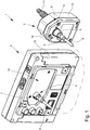
- Fig. 1 shows schematically in a perspective view a preferred embodiment of a device 1 according to the invention for measuring a gas pressure in a first state.
- the device 1 has a gas pressure measuring device 2 with a gas pressure sensor 3.
- the device 1 also has an operating device 4 and a connecting device 5 for connecting the gas pressure measuring device 2 to the operating device 4, so that data can be transmitted from the gas pressure measuring device 2 via the connecting device 5 to the operating device 4.
- the gas pressure measuring device 2 has an interface 6 and the operating device 4 has an interface 7.
- the interfaces 6, 7 can be mechanically connected directly to carry out a gas pressure measurement, so that data from the interface 6 of the gas pressure measuring device 2 can be transmitted directly to the interface 7 of the operating device 4.
- the gas pressure measuring device 2 for performing a gas pressure measurement can be separated from the operating device 4 in such a way that data can be transmitted from the gas pressure measuring device 2 to the operating device 4 via the connecting device 5.
- connection device 5 here has a wired connection means 8 which is releasably attached to both interfaces 6, 7, so that in this first state data can be transmitted from the interface 6 of the gas pressure measuring device 2 via the wired connection means 8 to the interface 7 of the operating device 4.
- the wired connection means 8 is located here completely outside the gas pressure measuring device 2 and completely outside the operating device 4.
- the gas pressure measuring device 2 can be positioned near an apparatus for which a gas pressure measurement is to be carried out.
- the connecting device 5 has an adapter 9, by means of which the cable-connected connecting means 8 can be connected to the interface 6 of the gas pressure measuring device 2.
- the adapter 9 is arranged on the interface 6 of the gas pressure measuring device 2, in particular fastened in a detachable manner, before the wired connection means is connected.
- the adapter 9 has an anti-twist device 10.
- the anti-rotation device 10 is formed in the illustrated embodiment by a projection and a recess.
- the interface 6 of the gas pressure measuring device 2 has a recess into which a projection of the adapter 9 can fit so that the rotation is limited or avoided by a stop of the projection on the walls of the recess.
- the operating device 4 has a supporting device 11.
- the support device 11 serves to support the device 1 and is designed as a so-called folding foot in the illustrated embodiment.
- FIG. 1 shows that, in the preferred exemplary embodiment shown here, a docking point 12 is provided on the operating device 4.
- the gas pressure measuring device 2 can be attached to the docking point 12.
- the Fig. 1 shows that the docking point 12 on the operating device 4 is designed as a mechanical formation for the correct alignment of the gas pressure measuring device 2.
- the in Fig. 1 The illustrated embodiment also shows that the gas pressure measuring device 2 has a connection 13 to which a gas-tight line can be connected for connection to an apparatus in which a gas pressure is to be measured.
- Fig. 2 shows schematically the device 1 from Fig. 1 in a second state.
- the interface 6 can now be mechanically connected directly to one another with the interface 7.
- both interfaces 6, 7 are designed as complementary plug connectors, whereby they can be mechanically connected directly to one another by means of a form fit.
- the interface 6 of the gas pressure measuring device 2 is designed as a built-in plug and the interface 7 of the operating device 4 is designed as a socket.
- the wired connection means 8 has two plug-in connectors that are complementary to one of the interfaces 6, 7, in particular a plug and a coupling.
- Fig. 3 shows schematically the device 1 from Fig. 1 in a third state.
- the interfaces 6, 7 are mechanically directly connected to one another.
- the gas pressure measuring device 2 is releasably attached to the operating device 4. This enables a compact arrangement of the gas pressure measuring device 2 and the operating device 4 when carrying out a gas pressure measurement.
- the gas pressure measuring device 2 can be separated again from the operating device 4, wherein data can be transmitted from the gas pressure measuring device 2 to the operating device 4 via the connecting device 5.
- the wired connection means 8 can be connected to the interfaces 6, 7.
- Fig. 4 shows schematically a rear view of the device 1 from FIG Fig. 3 .
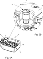
- Figure 5A shows schematically in a perspective view the gas pressure measuring device 2 of the device 1 from Fig. 1 .
- Figure 5B shows schematically an enlarged section of the gas pressure measuring device 2 from Figure 5A .
- the formation of the interface 6 of the gas pressure measuring device 2 as a built-in connector can be seen.
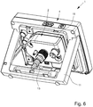
- Fig. 6 schematically in a perspective view the device 1 from Fig. 3 in a fourth state.
- Fig. 7 shows schematically a side view of the device 1 from FIG Fig. 6 .
- the support device 11 is folded out to support the operating device.
- the gas pressure measuring device 2 is attached to the operating device 4.
- FIG. 11 shows schematically a front view of the device from FIG Fig. 1 . It can be seen here that the operating device 4 in the preferred exemplary embodiment shown here has a touch-sensitive display means 14.
- the touch-sensitive display means 14 is designed as a touch display.
Landscapes
- Physics & Mathematics (AREA)
- General Physics & Mathematics (AREA)
- Measuring Fluid Pressure (AREA)
Description
- Die vorliegende Erfindung betrifft eine Vorrichtung zur Messung und Regelung eines Gasdrucks gemäß dem Oberbegriff von Anspruch 1.
- Gasdruckmessvorrichtungen sind in verschiedenen Ausführungsformen bekannt. Sie werden häufig auch als Vakuummessgeräte oder Vakuummeter bezeichnet. Sie dienen zur Messung des physikalischen Drucks eines Gases oder Gasgemisches in einer abgeschlossenen Apparatur. In den meisten Anwendungen wird der absolute Gasdruck - also bezogen auf ein Vakuum - gemessen.
- Gasdruckmessvorrichtungen der in Rede stehenden Art weisen eine Gasdruckmesseinrichtung und eine Bedieneinrichtung auf. Die Gasdruckmesseinrichtung hat einen Drucksensor, der einen physikalischen Gasdruck in eine zu diesem Gasdruck in eindeutiger Beziehung stehende, z.B. proportionale, elektrische Ausgangsgröße umwandelt. Bekannt sind z. B. Drucksensoren mit einer Membran aus Aluminiumoxid-Keramik. Zur Gasdruckmessung wird die Gasdruckmesseinrichtung mit der Apparatur verbunden, z. B. mittels einer gasdichten Leitung.
- Die gasdichte Leitung zur Apparatur ist meist unflexibel und darf nicht zu lang sein, um eine gewünschte Messgenauigkeit zu erreichen. Vorteilhaft ist demnach eine Positionierung der Gasdruckmesseinrichtung nahe der Apparatur. Daher sind aus der Praxis Gasdruckmessvorrichtungen bekannt, bei denen die Gasdruckmesseinrichtung von der Bedieneinrichtung dauerhaft separat ausgebildet und gegenüber der Bedieneinrichtung beweglich ist. Die Gasdruckmessvorrichtung hat dabei eine Verbindungseinrichtung zur Verbindung der Gasdruckmesseinrichtung mit der Bedieneinrichtung, so dass Daten von der Gasdruckmesseinrichtung über die Verbindungseinrichtung zur Bedieneinrichtung übertragbar sind.
- Demgegenüber ist häufig eine kompakte Anordnung von Gasdruckmesseinrichtung und Bedieneinrichtung gewünscht. Daher sind aus der Praxis Gasdruckmessvorrichtungen bekannt, bei denen die Gasdruckmesseinrichtung und die Bedieneinrichtung dauerhaft in einem gemeinsamen Gehäuse angeordnet und zueinander unbeweglich sind. Auch hier hat die Gasdruckmessvorrichtung eine Verbindungseinrichtung zur Verbindung der Gasdruckmesseinrichtung mit der Bedieneinrichtung, so dass Daten von der Gasdruckmesseinrichtung über die Verbindungseinrichtung zur Bedieneinrichtung übertragbar sind. Allerdings ist die Verbindungseinrichtung ebenfalls in dem Gehäuse angeordnet.
- Beide Arten der bekannten Gasdruckmessvorrichtungen können jeweils nur eine der beiden Anforderungen (Positionierung der Gasdruckmesseinrichtung möglichst nahe der Apparatur bzw. möglichst kompakte Anordnung von Gasdruckmesseinrichtung und Bedieneinrichtung) erfüllen.
- Aus dem Dokument
DE 20 2008 000 837 U1 ist ein digitaler Kühlmitteldruckmesser bekannt, der beim Füllen eines Kühlmittels in eine Klimaanlage den Kühlmitteldruck messen und das Messergebnis auf einem Display anzeigen kann. Beim Füllen des Kühlmittels in die Klimaanlage wird die Füllmenge durch den Kühlmitteldruckmesser gesteuert. Dieser Kühlmitteldruckmesser hat eine Bedieneinrichtung mit einem Gehäuse, einem Display und zwei Steuerschaltern. Das Display ist über einen Hochdruck-/Niederdrucksensor mit den Steuerschaltern verbunden. Die Bedieneinrichtung kann über ein Kabel mit einem Thermoelement-Vakuumsensor verbunden werden, durch den der Vakuumzustand im Kühlmittelrohr gemessen werden kann. Wenn das Kühlmittel Fremdstoffe enthält, muss die Klimaanlage zunächst mit einer Vakuumpumpe evakuiert und dann erneut mit einem Kühlmittel gefüllt werden. Außerdem kann die Bedieneinrichtung über ein anderes Kabel mit einem Hochdruck-/Niederdrucktemperatursensor verbunden werden, um die Hochdruck- und Niederdrucktemperatur zu messen. Der Hochdruck-/Niederdrucksensor kann ausschließlich den durch das flüssige Kühlmittel im Kühlmittelrohr verursachten Druck messen. Der Hochdruck-/Niederdrucktemperatursensor kann ausschließlich die Temperatur des flüssigen Kühlmittels messen. Nur der Thermoelement-Vakuumsensor kann einen Gasdruck, und zwar den im Kühlmittelrohr herrschenden Gasdruck, messen. - Aufgabe der vorliegenden Erfindung ist es, die aus der Praxis bekannten Vorrichtungen zur Messung eines Gasdrucks hinsichtlich Nutzungsmöglichkeiten, Handhabung und/oder Anpassbarkeit zu verbessern.
- Die obige Aufgabe wird durch eine Vorrichtung zur Messung eines Gasdrucks gemäß Anspruch 1 gelöst. Vorteilhafte Weiterbildungen sind Gegenstand der Unteransprüche.
- Die Grundidee der vorliegenden Erfindung besteht darin, eine Gasdruckmesseinrichtung bereitzustellen, die zur Durchführung einer Gasdruckmessung sowohl unmittelbar an der Bedieneinrichtung angeordnet als auch von der Bedieneinrichtung separiert sein kann.
- Dazu weist die erfindungsgemäße Vorrichtung eine Verbindungseinrichtung zur Verbindung der Gasdruckmesseinrichtung mit der Bedieneinrichtung auf, so dass Daten von der Gasdruckmesseinrichtung indirekt, also über die Verbindungseinrichtung, zur Bedieneinrichtung übertragbar sind. Die Verbindungseinrichtung befindet sich zumindest teilweise, vorzugsweise vollständig, außerhalb der Gasdruckmesseinrichtung und zumindest teilweise, vorzugsweise vollständig, außerhalb der Bedieneinrichtung.
- Erfindungsgemäß ist vorgesehen, dass die Gasdruckmesseinrichtung und die Bedieneinrichtung jeweils eine Schnittstelle aufweisen, die, insbesondere zur Durchführung einer Gasdruckmessung, mechanisch unmittelbar miteinander verbindbar sind, so dass Daten von der Schnittstelle der Gasdruckmesseinrichtung direkt, also ohne Verwendung der Verbindungseinrichtung bzw. unter Umgehung der Verbindungseinrichtung, zur Schnittstelle der Bedieneinrichtung übertragbar sind. Dies ermöglicht eine kompakte Anordnung von Gasdruckmesseinrichtung und Bedieneinrichtung bei Durchführung einer Gasdruckmessung.
- Außerdem ist erfindungsgemäß vorgesehen, dass, insbesondere zur Durchführung einer Gasdruckmessung, die Gasdruckmesseinrichtung von der Bedieneinrichtung derart separierbar ist, dass Daten von der Gasdruckmesseinrichtung über die Verbindungseinrichtung zur Bedieneinrichtung übertragbar sind. Die Gasdruckmesseinrichtung ist in diesem Fall also gegenüber der Bedieneinrichtung beweglich. Dies ermöglicht eine Positionierung der Gasdruckmesseinrichtung nahe einer Apparatur, für die eine Gasdruckmessung durchgeführt werden soll, bzw. eine geringe Länge einer die Apparatur und die Gasdruckmesseinrichtung verbindenden gasdichten Leitung, was vorteilhaft im Hinblick auf die Messgenauigkeit ist.
- Die erfindungsgemäße Vorrichtung ermöglicht also zwei unterschiedliche Messaufbauten. Zum einen kann die Gasdruckmesseinrichtung mechanisch unmittelbar mit der Bedieneinrichtung verbunden sein. Zum anderen kann die Gasdruckmesseinrichtung von der Bedieneinrichtung separiert und ihr gegenüber beweglich sein. Zwischen diesen beiden Messaufbauten kann gewechselt werden. Damit erfüllt die erfindungsgemäße Vorrichtung die Anforderungen für beide Einsatzzwecke, also Positionierung der Gasdruckmesseinrichtung möglichst nahe der Apparatur bzw. möglichst kompakte Anordnung von Gasdruckmesseinrichtung und Bedieneinrichtung. Sie ist flexibel einsetzbar, je nach Einsatzzweck anpassbar und einfach handhabbar.
- Statt wie bisher zwei unterschiedliche, dedizierte Gasdruckmessvorrichtungen vorzuhalten, hat der Nutzer mit der erfindungsgemäßen Vorrichtung ein einziges Gerät, bei dem er entscheiden kann, an welcher Stelle die Gasdruckmesseinrichtung - in Abhängigkeit der durchzuführenden Messung - angeordnet werden soll. Dies reduziert Kosten und Platzbedarf.
- In beiden Möglichkeiten der Anordnung der Gasdruckmesseinrichtungen kann die Gasdruckmesseinrichtung Daten, die die Messung des Gasdrucks betreffen, an die Bedieneinrichtung übertragen. Im mechanisch verbundenen Zustand erfolgt die Übertragung über die jeweiligen Schnittstellen der Gasdruckmesseinrichtung und der Bedieneinrichtung. Im separierten Zustand ist eine Datenübertragung über die Verbindungseinrichtung vorgesehen.
- Außerdem ist erfindungsgemäß vorgesehen, dass an der Bedieneinrichtung eine Andockstelle vorgesehen ist, an der die Gasdruckmesseinrichtung anbringbar ist. Die Andockstelle ist Kann an der Bedieneinrichtung als mechanische Ausformung zur korrekten Ausrichtung der Gasdruckmesseinrichtung, als mechanische Rasthalterung, Steckhalterung und/oder Magnethalterung ausgebildet.
- Zusätzlich zur Verbindung der Schnittstellen der Gasdruckmesseinrichtung und der Bedieneinrichtung kann die Andockstelle zur sicheren Fixierung und zur stabilen lösbaren Verbindung der Gasdruckmesseinrichtung mit der Bedieneinrichtung beitragen.
- Im Bereich der Andockstelle kann die Schnittstelle der Bedieneinrichtung angeordnet sein, so dass die Schnittstellen im unmittelbar mechanisch verbundenen Zustand im Bereich der Andockstelle angeordnet sind.
- Zudem kann vorteilhafterweise durch die Andockstelle dem Nutzer visualisiert werden, in welcher Position die Gasdruckmesseinrichtung an der Bedieneinrichtung anzubringen ist. Die Andockstelle kann korrespondierend zu der/dem an der Bedieneinrichtung anzuordnenden Fläche und/oder Bereich der Gasdruckmesseinrichtung ausgebildet sein.
- Bei einer bevorzugten Ausführungsform der Erfindung sind die Schnittstellen so ausgebildet, dass bei mechanisch unmittelbar verbundenen Schnittstellen die Gasdruckmesseinrichtung an der Bedieneinrichtung lösbar befestigt ist. Die Schnittstellen übernehmen also nicht nur die Funktion einer Datenverbindung sondern auch einer mechanischen Befestigung bzw. Halterung. Im mechanisch verbundenen Zustand ist die Gasdruckmesseinrichtung sicher an der Bedieneinrichtung fixiert. Die mechanische Befestigung kann form- und/oder kraftschlüssig erfolgen. Wichtig ist, dass die mechanische Befestigung lösbar ist, da die Gasdruckmesseinrichtung von der Bedieneinrichtung separierbar sein muss, was ein mechanisches Trennen der Schnittstelle der Gasdruckmesseinrichtung von der Schnittstelle der Bedieneinrichtung bedingt.
- Vorteilhafterweise sind die beiden Schnittstellen als komplementäre Steckverbinder ausgebildet. Die Steckverbinder können mittels Formschluss miteinander verbindbar sein, vorzugsweise wobei die Schnittstelle der Bedieneinrichtung als Buchse und die Schnittstelle der Gasdruckmesseinrichtung als Einbaustecker ausgebildet sind. Eine komplementäre Ausbildung der Schnittstellen als Steckverbinder ist insbesondere im Hinblick auf die Handhabung, Stabilität und Kosten vorteilhaft.
- Die Ausbildung der Schnittstellen als Steckverbinder ermöglicht die elektrische Kontaktierung der Gasdruckmesseinrichtung zu der Bedieneinrichtung. Im elektrisch kontaktierten Zustand ist ein Datenaustausch zwischen der Gasdruckmesseinrichtung und der Bedieneinrichtung gewährleistet.
- Gemäß einer vorteilhaften Ausgestaltung des Erfindungsgedankens ist vorgesehen, dass die Verbindungseinrichtung ein kabelgebundenes Verbindungsmittel aufweist. Das kabelgebundene Verbindungsmittel kann an beide Schnittstellen lösbar befestigt sein, so dass Daten von der Schnittstelle der Gasdruckmesseinrichtung über die Verbindungseinrichtung, insbesondere über das kabelgebundene Verbindungsmittel, zur Schnittstelle der Bedieneinrichtung übertragbar sind, wenn die Gasdruckmesseinrichtung von der Bedieneinrichtung separiert ist. Das kabelgebundene Verbindungsmittel verbindet die Gasdruckmesseinrichtung mit der Bedieneinrichtung elektrisch kontaktierend. Durch das kabelgebundene Verbindungsmittel kann die Gasdruckmesseinrichtung möglichst nahe der Apparatur angeordnet werden, so dass insbesondere die an die Gasdruckmesseinrichtung anzuordnende gasdichte Leitung, die die Apparatur mit der Gasdruckmesseinrichtung verbindet, eine möglichst geringe Länge aufweist. Da über das kabelgebundene Verbindungsmittel lediglich Daten ausgetauscht werden, beeinflusst die Länge des kabelgebundenen Verbindungsmittels nicht die Messgenauigkeit der Gasdruckmessung.
- Vorzugsweise weist das kabelgebundene Verbindungsmittel zwei jeweils zu einer Schnittstelle komplementäre Steckverbinder, insbesondere einen Stecker und eine Kupplung, auf. Hierfür kann das an die Schnittstelle der Gasdruckmesseinrichtung anzuordnende Ende des Verbindungsmittels eine Kupplung und das an die Schnittstelle der Bedieneinrichtung anzuordnende Endstück des Verbindungsmittels einen Stecker aufweisen, wobei der Stecker des Verbindungsmittels mit der Buchse der Bedieneinrichtung und die Kupplung des Verbindungsmittels mit dem Einbaustecker der Gasdruckmesseinrichtung formschlüssig verbunden werden kann, so dass eine elektrische Kontaktierung und ein Datenaustausch sichergestellt ist. Durch die Steckverbinder des kabelgebundenen Verbindungsmittels kann eine stabile jedoch lösbare Verbindung der Gasdruckmesseinrichtung zu der Bedieneinrichtung gewährleistet werden. Sie erlauben eine einfache Handhabung und eine kostengünstige Konstruktion.
- Darüber hinaus ist bei einer bevorzugten Ausführungsvariante der Erfindung vorgesehen, dass die Verbindungseinrichtung einen Adapter aufweist, mittels dem das kabelgebundene Verbindungsmittel mit der Schnittstelle der Gasdruckmesseinrichtung verbindbar ist. Der Adapter kann eine Verdrehsicherung aufweisen. Die Verdrehsicherung verhindert ein relatives Verdrehen des Verbindungsmittels zu der Schnittstelle der Gasdruckmesseinrichtung. Der Adapter wird vorzugsweise an dem Einbaustecker der Gasdruckmesseinrichtung angeordnet. Ferner kann die Verdrehsicherung die formschlüssige Verbindung des Verbindungsmittels zu der Schnittstelle der Gasdruckmesseinrichtung unterstützen. Die Verdrehsicherung kann durch das Einrasten eines Vorsprunges in eine dazu korrespondierende Vertiefung erzielt werden. Beispielsweise kann der Adapter einen Vorsprung und/oder eine Ausnehmung aufweisen, die korrespondierend zu einer Ausnehmung und/oder einem Vorsprung der Schnittstelle der Gasdruckmesseinrichtung ausgebildet ist, wobei sich im verbundenen Zustand des Adapters zu der als Einbaustecker ausgebildeten Schnittstelle der Gasdruckmesseinrichtung eine verdrehsichere, formschlüssige Verbindung ergibt. Ein Verdrehen wird durch den Anschlag des Vorsprunges an der Ausnehmung vermieden.
- Eine Übertragung von Daten von der Gasdruckmesseinrichtung zu der Bedieneinrichtung kann über die mechanisch unmittelbare Verbindung der Schnittstellen, über das kabelgebundene Verbindungsmittel und/oder drahtlos erfolgen. Bei einer bevorzugten Ausführungsform der Erfindung umfasst die Verbindungseinrichtung einen der Gasdruckmesseinrichtung zugeordneten Transceiver und einen der Bedieneinrichtung zugeordneten Transceiver. Über die Transceiver können drahtlos Daten von der Gasdruckmesseinrichtung zur Bedieneinrichtung übertragen werden. Hierbei kann die Gasdruckmesseinrichtung mit der Bedieneinrichtung unmittelbar mechanisch verbunden oder die Gasdruckmesseinrichtung von der Bedieneinrichtung separiert sein. Bei einer separierten Anordnung der Gasdruckmesseinrichtung von der Bedieneinrichtung sind diese Einrichtungen über die Verbindungseinrichtung miteinander verbunden. Die Verbindungseinrichtung kann demgemäß zum Datenaustausch die jeweiligen Transceiver und/oder das kabelgebundene Verbindungsmittel aufweisen.
- Des Weiteren kann die Bedieneinrichtung vorteilhafterweise eine Stützeinrichtung aufweisen, die auch dann ausklappbar ist, wenn die Gasdruckmesseinrichtung an der Bedieneinrichtung befestigt ist. Die Stützeinrichtung ist zur Stützung der Bedieneinrichtung ausgebildet und kann die Form eines sogenannten Klappfußes aufweisen. Ein Ausklappen der Stützeinrichtung kann in Abhängigkeit des jeweiligen Einsatzzweckes vorgenommen werden. Die Stützeinrichtung kann unabhängig von der Anordnung der Gasdruckmesseinrichtung genutzt werden, das heißt die Stützeinrichtung kann zur Stützung der Bedieneinrichtung im mechanisch unmittelbar verbundenen Zustand der Bedieneinrichtung mit der Gasdruckmesseinrichtung und im separierten Zustand der Gasdruckmesseinrichtung von der Bedieneinrichtung zur Stützung der Bedieneinrichtung verwendet werden.
- Im Übrigen ist gemäß einer bevorzugten Ausführungsform des Erfindungsgedankens vorgesehen, dass die Bedieneinrichtung mindestens ein berührungsempfindliches Anzeigemittel aufweist. Das berührungsempfindliche Anzeigemittel kann als Touchdisplay ausgebildet sein.
- Die erfindungsgemäße Vorrichtung kann zum Regeln eines Gasdrucks ausgebildet sein, insbesondere zur Ausgabe von Steuersignalen an ein Stellglied eines Regelkreises. Solch ein Stellglied kann z. B. ein Motor einer Vakuumpumpe oder ein Ventil zwischen einer Vakuumpumpe und der Apparatur sein.
- Dabei ist es vorteilhaft, wenn ein Nutzer der erfindungsgemäßen Vorrichtung über die Bedieneinrichtung durch Eingabe von Informationen den Gasdruck in der Apparatur regeln und/oder steuern kann und/oder Informationen zu dem Gasdruck der Apparatur mittels des Anzeigemittels angezeigt bekommt. Eine Bedienung über ein berührungsempfindliches Anzeigemittel ist besonders nutzerfreundlich, da die Nutzer an die Verwendung von berührungsempfindlichen Anzeigemitteln gewöhnt sind und die Möglichkeit einer Vielzahl von Einstellungen bei einer kleinen Bedienfläche des Anzeigemittels dem Nutzer zur Verfügung gestellt werden kann. Eine Bedienung kann beispielsweise durch sogenannte Wischgesten und/oder ein Antippen von bestimmten Symbolen erfolgen.
- Im Bereich der Andockstelle kann an der der Gasdruckmesseinrichtung zugewandten Seite der Bedieneinrichtung und/oder an der der Bedieneinrichtung zugewandten Seite der Gasdruckmesseinrichtung wenigstens ein Abdichtungsmittel, vorzugsweise eine Elastomer-Dichtscheibe, angeordnet sein. Das Abdichtungsmittel kann zudem derart ausgebildet sein, dass es die Andockstelle im unmittelbar mechanisch verbundenen Zustand der Schnittstellen abdichtet, so dass die Schnittstellen geschützt sind.
- Im Übrigen kann der Gasdrucksensor der Gasdruckmesseinrichtung den Druck direkt oder indirekt messen. Bei einer indirekten Gasdruckmessung kann beispielsweise eine Kraft pro Flächeneinheit gemessen werden, die als Rückschluss auf den vorhandenen Druck genutzt werden kann. Zur Messung des Gasdrucks, der vorzugsweise im Bereich des Vakuums vorgesehen ist, kann auf die DIN 28400 verwiesen werden.
- Weitere Merkmale, Vorteile und Anwendungsbereiche der vorliegenden Erfindung ergeben sich aus der nachfolgenden Beschreibung von Ausführungsbeispielen anhand der Zeichnungen und der Zeichnung selbst. Dabei bilden alle beschriebenen und/oder bildlich dargestellten Merkmale für sich oder in beliebiger Kombination den Gegenstand der vorliegenden Erfindung, unabhängig von ihrer Zusammenfassung oder deren Rückbeziehung.
- In der Zeichnung zeigt
- Fig. 1
- schematisch in einer perspektivischen Ansicht eine bevorzugte Ausführungsform einer erfindungsgemäßen Vorrichtung zur Messung eines Gasdrucks in einem ersten Zustand;
- Fig. 2
- schematisch in einer perspektivischen Ansicht die Vorrichtung aus
Fig. 1 in einem zweiten Zustand; - Fig. 3
- schematisch in einer perspektivischen Ansicht die Vorrichtung aus
Fig. 2 in einem dritten Zustand; - Fig. 4
- schematisch eine Rückansicht der Vorrichtung aus
Fig. 3 ; - Fig. 5A
- schematisch in einer perspektivischen Ansicht eine Gasdruckmesseinrichtung der Vorrichtung aus
Fig. 1 ; - Fig. 5B
- schematisch einen vergrößerten Ausschnitt der Gasdruckmesseinrichtung aus
Fig. 5A ; - Fig. 6
- schematisch in einer perspektivischen Ansicht die Vorrichtung aus
Fig. 3 in einem vierten Zustand; - Fig. 7
- schematisch eine Seitenansicht der Vorrichtung aus
Fig. 6 ; und - Fig. 8
- schematisch eine Frontansicht der Vorrichtung aus
Fig. 1 . -
Fig. 1 zeigt schematisch in einer perspektivischen Ansicht eine bevorzugte Ausführungsform einer erfindungsgemäßen Vorrichtung 1 zur Messung eines Gasdrucks in einem ersten Zustand. Die Vorrichtung 1 weist eine Gasdruckmesseinrichtung 2 mit einem Gasdrucksensor 3 auf. Ferner weist die Vorrichtung 1 eine Bedieneinrichtung 4 und eine Verbindungseinrichtung 5 zur Verbindung der Gasdruckmesseinrichtung 2 mit der Bedieneinrichtung 4 auf, so dass Daten von der Gasdruckmesseinrichtung 2 über die Verbindungseinrichtung 5 zur Bedieneinrichtung 4 übertragbar sind. - Die Gasdruckmesseinrichtung 2 weist eine Schnittstelle 6 und die Bedieneinrichtung 4 eine Schnittstelle 7 auf. Die Schnittstellen 6, 7 sind zur Durchführung einer Gasdruckmessung mechanisch unmittelbar verbindbar, so dass Daten von der Schnittstelle 6 der Gasdruckmesseinrichtung 2 direkt zur Schnittstelle 7 der Bedieneinrichtung 4 übertragbar sind.
- Zusätzlich ist die Gasdruckmesseinrichtung 2 zur Durchführung einer Gasdruckmessung von der Bedieneinrichtung 4 derart separierbar, dass Daten von der Gasdruckmesseinrichtung 2 über die Verbindungseinrichtung 5 zur Bedieneinrichtung 4 übertragbar sind.
- In dem in
Fig. 1 dargestellten ersten Zustand ist die Gasdruckmesseinrichtung 2 von der Bedieneinrichtung 4 separiert. Die Verbindungseinrichtung 5 weist hier ein kabelgebundenes Verbindungsmittel 8 auf, das an beide Schnittstellen 6, 7 lösbar befestigt ist, so dass in diesem ersten Zustand Daten von der Schnittstelle 6 der Gasdruckmesseinrichtung 2 über das kabelgebundene Verbindungsmittel 8 zur Schnittstelle 7 der Bedieneinrichtung 4 übertragbar sind. Das kabelgebundene Verbindungsmittel 8 befindet sich hier vollständig außerhalb der Gasdruckmesseinrichtung 2 und vollständig außerhalb der Bedieneinrichtung 4. - In diesem ersten Zustand kann die Gasdruckmesseinrichtung 2 nahe einer Apparatur, für die eine Gasdruckmessung durchgeführt werden soll, positioniert werden.
- Bei dem in
Fig. 1 dargestellten Ausführungsbeispiel weist die Verbindungseinrichtung 5 einen Adapter 9 auf, mittels dem das kabelgebundene Verbindungsmittel 8 mit der Schnittstelle 6 der Gasdruckmesseinrichtung 2 verbindbar ist. Der Adapter 9 wird vor dem Verbinden des kabelgebundenen Verbindungsmittels an der Schnittstelle 6 der Gasdruckmesseinrichtung 2 angeordnet, insbesondere lösbar befestigt. - Der Adapter 9 weist eine Verdrehsicherung 10 auf. Die Verdrehsicherung 10 ist in dem dargestellten Ausführungsbeispiel durch einen Vorsprung und eine Ausnehmung gebildet. Hierfür weist die Schnittstelle 6 der Gasdruckmesseinrichtung 2 eine Ausnehmung auf, in die ein Vorsprung des Adapters 9 einfassen kann, so dass das Verdrehen durch einen Anschlag des Vorsprungs an die Wandungen der Ausnehmung begrenzt ist bzw. vermieden wird.
- Ferner weist die Bedieneinrichtung 4 bei dem hier dargestellten und bevorzugten Ausführungsbeispiel eine Stützeinrichtung 11 auf. Die Stützeinrichtung 11 dient zur Abstützung der Vorrichtung 1 und ist in dem dargestellten Ausführungsbeispiel als sogenannter Klappfuß ausgebildet.
- Im Übrigen zeigt
Fig. 1 , dass bei dem hier dargestellten und bevorzugten Ausführungsbeispiel an der Bedieneinrichtung 4 eine Andockstelle 12 vorgesehen ist. An die Andockstelle 12 kann die Gasdruckmesseinrichtung 2 angebracht werden. DieFig. 1 zeigt, dass die Andockstelle 12 an der Bedieneinrichtung 4 als mechanische Ausformung zur korrekten Ausrichtung der Gasdruckmesseinrichtung 2 ausgebildet ist. - Bei dem in
Fig. 1 dargestellten Ausführungsbeispiel ist außerdem gezeigt, dass die Gasdruckmesseinrichtung 2 einen Anschluss 13 aufweist, an dem eine gasdichte Leitung anschließbar ist zur Verbindung mit einer Apparatur, in der ein Gasdruck gemessen werden soll. -
Fig. 2 zeigt schematisch die Vorrichtung 1 ausFig. 1 in einem zweiten Zustand. Hier ist die Verbindungseinrichtung 5 samt dem Adapter 9 von den Schnittstellen 6, 7 gelöst. Die Schnittstelle 6 kann nun mit der Schnittstelle 7 mechanisch unmittelbar miteinander verbunden werden. - In
Fig. 2 ist zu erkennen, dass bei diesem Ausführungsbeispiel beide Schnittstellen 6, 7 als komplementäre Steckverbinder ausgebildet sind, wobei sie mittels Formschluss mechanisch unmittelbar miteinander verbindbar sind. Insbesondere ist die Schnittstelle 6 der Gasdruckmesseinrichtung 2 als Einbaustecker und die Schnittstelle 7 der Bedieneinrichtung 4 als Buchse ausgebildet. Nicht dargestellt ist, dass das kabelgebundene Verbindungsmittel 8 zwei jeweils zu einer der Schnittstellen 6, 7 komplementäre Steckverbinder, insbesondere einen Stecker und eine Kupplung, aufweist. -
Fig. 3 zeigt schematisch die Vorrichtung 1 ausFig. 1 in einem dritten Zustand. Hier sind die Schnittstellen 6, 7 mechanisch unmittelbar miteinander verbunden. Die Gasdruckmesseinrichtung 2 ist an der Bedieneinrichtung 4 lösbar befestigt. Dies ermöglicht eine kompakte Anordnung von Gasdruckmesseinrichtung 2 und Bedieneinrichtung 4 bei Durchführung einer Gasdruckmessung. - Erfindungsgemäß ist vorgesehen, dass, insbesondere zur Durchführung einer Gasdruckmessung, die Gasdruckmesseinrichtung 2 von der Bedieneinrichtung 4 wieder separierbar ist, wobei Daten von der Gasdruckmesseinrichtung 2 über die Verbindungseinrichtung 5 zur Bedieneinrichtung 4 übertragbar sind. Dazu kann das kabelgebundene Verbindungsmittel 8 an die Schnittstellen 6, 7 angeschlossen werden.
-
Fig. 4 zeigt schematisch eine Rückansicht der Vorrichtung 1 ausFig. 3 .Fig. 5A zeigt schematisch in einer perspektivischen Ansicht die Gasdruckmesseinrichtung 2 der Vorrichtung 1 ausFig. 1 .Fig. 5B zeigt schematisch einen vergrößerten Ausschnitt der Gasdruckmesseinrichtung 2 ausFig. 5A . Hier ist u. a. die Ausbildung der Schnittstelle 6 der Gasdruckmesseinrichtung 2 als Einbaustecker zu erkennen. -
Fig. 6 schematisch in einer perspektivischen Ansicht die Vorrichtung 1 ausFig. 3 in einem vierten Zustand.Fig. 7 zeigt schematisch eine Seitenansicht der Vorrichtung 1 ausFig. 6 . In dem inFig. 6 und7 gezeigten vierten Zustand ist die Stützeinrichtung 11 zur Stützung der Bedieneinrichtung ausgeklappt. Dabei ist die Gasdruckmesseinrichtung 2 an der Bedieneinrichtung 4 befestigt. -
Fig. 8 zeigt schematisch eine Frontansicht der Vorrichtung ausFig. 1 . Hier ist zu sehen, dass die Bedieneinrichtung 4 bei dem hier dargestellten und bevorzugten Ausführungsbeispiel ein berührungsempfindliches Anzeigemittel 14 aufweist. Das berührungsempfindliche Anzeigemittel 14 ist als Touchdisplay ausgebildet. -
- 1
- Vorrichtung
- 2
- Gasdruckmesseinrichtung
- 3
- Gasdrucksensor
- 4
- Bedieneinrichtung
- 5
- Verbindungseinrichtung
- 6
- Schnittstelle von 2
- 7
- Schnittstelle von 4
- 8
- Verbindungsmittel
- 9
- Adapter
- 10
- Verdrehsicherung
- 11
- Stützeinrichtung
- 12
- Andockstelle
- 13
- Anschluss von 2
- 14
- Anzeigemittel von 4
- 15
- Gehäuse von 2
Claims (14)
- Vorrichtung (1) zur Messung und Regelung eines Gasdrucks in einer geschlossenen Apparatur, wobei die Vorrichtung (1) Folgendes umfasst:- eine Gasdruckmesseinrichtung (2) mit einem Gasdrucksensor (3),- eine Bedieneinrichtung (4) und
eine Verbindungseinrichtung (5) zur Verbindung der Gasdruckmesseinrichtung (2) mit der Bedieneinrichtung (4), so dass Daten von der Gasdruckmesseinrichtung (2) über die Verbindungseinrichtung (5) zur Bedieneinrichtung (4) übertragbar sind, wobei die Gasdruckmesseinrichtung (2) und die Bedieneinrichtung (4) jeweils eine Schnittstelle (6, 7) aufweisen, die, insbesondere zur Durchführung einer Gasdruckmessung, mechanisch unmittelbar miteinander verbindbar sind, so dass Daten von der Schnittstelle (6) der Gasdruckmesseinrichtung (2) direkt zur Schnittstelle (7) der Bedieneinrichtung (4) übertragbar sind und
wobei, insbesondere zur Durchführung einer Gasdruckmessung, die Gasdruckmesseinrichtung (2) von der Bedieneinrichtung (4) derart separierbar ist, dass Daten von der Gasdruckmesseinrichtung (2) über die Verbindungseinrichtung (5) zur Bedieneinrichtung (4) übertragbar sind wobei an der Bedieneinrichtung (4) eine Andockstelle (12) vorgesehen ist, an der die Gasdruckmesseinrichtung (2) anbringbar ist und
dass die Andockstelle (12) an der Bedieneinrichtung (4) als mechanische Ausformung zur korrekten Ausrichtung der Gasdruckmesseinrichtung (2), als mechanische Rasthalterung, Steckhalterung und/oder Magnethalterung ausgebildet ist. - Vorrichtung nach Anspruch 1, dadurch gekennzeichnet, dass die Vorrichtung (1) zur Ausgabe von Steuersignalen an ein Stellglied eines Regelkreises ausgebildet ist.
- Vorrichtung nach Anspruch 1 oder 2, dadurch gekennzeichnet, dass durch Eingabe von Informationen in die Bedieneinrichtung (4) der Gasdruck in der Apparatur regelbar ist.
- Vorrichtung nach einem der vorhergehenden Ansprüche, dadurch gekennzeichnet, dass die Gasdruckmesseinrichtung (2) gegenüber der Bedieneinrichtung (4) beweglich ist, wenn die Gasdruckmesseinrichtung (2) von der Bedieneinrichtung (4) separiert ist.
- Vorrichtung nach einem der vorhergehenden Ansprüche, dadurch gekennzeichnet, dass die Schnittstellen (6, 7) so ausgebildet sind, dass bei mechanisch unmittelbar miteinander verbundenen Schnittstellen (6, 7) die Gasdruckmesseinrichtung (2) an der Bedieneinrichtung (4) lösbar befestigt ist und/oder
dass beide Schnittstellen (6, 7) als komplementäre Steckverbinder ausgebildet sind, die mittels Formschluss miteinander verbindbar sind, vorzugsweise wobei die Schnittstelle (7) der Bedieneinrichtung (4) als Buchse und die Schnittstelle (6) der Gasdruckmesseinrichtung (2) als Einbaustecker ausgebildet sind. - Vorrichtung nach einem der vorhergehenden Ansprüche, dadurch gekennzeichnet, dass die Verbindungseinrichtung (5) ein kabelgebundenes Verbindungsmittel (8) aufweist, das an beide Schnittstellen (6, 7) lösbar befestigbar ist, so dass Daten von der Schnittstelle (6) der Gasdruckmesseinrichtung (2) über die Verbindungseinrichtung (5) zur Schnittstelle (7) der Bedieneinrichtung (4) übertragbar sind, wenn die Gasdruckmesseinrichtung (2) von der Bedieneinrichtung (4) separiert ist.
- Vorrichtung nach Anspruch 6, dadurch gekennzeichnet, dass das kabelgebundene Verbindungsmittel (8) zwei zu jeweils einer Schnittstelle (6, 7) komplementäre Steckverbinder, insbesondere einen Stecker und eine Kupplung, aufweist.
- Vorrichtung nach Anspruch 6 oder 7, dadurch gekennzeichnet, dass die Verbindungseinrichtung (5) einen Adapter (9) aufweist, mittels dem das kabelgebundene Verbindungsmittel (8) mit der Schnittstelle (6) der Gasdruckmesseinrichtung (2) verbindbar ist, vorzugsweise wobei der Adapter (9) eine Verdrehsicherung (10) aufweist.
- Vorrichtung nach einem der vorhergehenden Ansprüche, dadurch gekennzeichnet, dass die Verbindungseinrichtung (5) einen der Gasdruckmesseinrichtung (2) zugeordneten Transceiver und einen der Bedieneinrichtung (4) zugeordneten Transceiver umfasst, mittels denen drahtlos Daten von der Gasdruckmesseinrichtung (2) zur Bedieneinrichtung (4) übertragbar sind.
- Vorrichtung nach einem der vorhergehenden Ansprüche, dadurch gekennzeichnet, dass die Bedieneinrichtung (4) eine Stützeinrichtung (11) aufweist, die ausklappbar ist, wenn die Gasdruckmesseinrichtung (2) an der Bedieneinrichtung (4) befestigt ist.
- Vorrichtung nach einem der vorhergehenden Ansprüche, dadurch gekennzeichnet, dass die Bedieneinrichtung (4) ein berührungsempfindliches Anzeigemittel (14) aufweist.
- Vorrichtung nach einem der vorhergehenden Ansprüche, dadurch gekennzeichnet, dass der Gasdrucksensor (3) in einem Gehäuse (15) der Gasdruckmesseinrichtung (2) angeordnet ist.
- Vorrichtung nach Anspruch 12, dadurch gekennzeichnet, dass die Schnittstelle (6) der Gasdruckmesseinrichtung (2) an dem Gehäuse (15) der Gasdruckmesseinrichtung (2) angeordnet ist.
- Vorrichtung nach einem der vorhergehenden Ansprüche, dadurch gekennzeichnet, dass die Gasdruckmesseinrichtung (2), vorzugsweise an einem Gehäuse (15) der Gasdruckmesseinrichtung (2), einen Anschluss (13) aufweist, an dem eine gasdichte Leitung anschließbar ist zur Verbindung mit der Apparatur.
Applications Claiming Priority (1)
| Application Number | Priority Date | Filing Date | Title |
|---|---|---|---|
| DE102018104265.5A DE102018104265A1 (de) | 2018-02-26 | 2018-02-26 | Vorrichtung zur Messung eines Gasdrucks |
Publications (2)
| Publication Number | Publication Date |
|---|---|
| EP3531096A1 EP3531096A1 (de) | 2019-08-28 |
| EP3531096B1 true EP3531096B1 (de) | 2021-05-12 |
Family
ID=65408951
Family Applications (1)
| Application Number | Title | Priority Date | Filing Date |
|---|---|---|---|
| EP19156423.6A Active EP3531096B1 (de) | 2018-02-26 | 2019-02-11 | Vorrichtung zur messung eines gasdrucks |
Country Status (2)
| Country | Link |
|---|---|
| EP (1) | EP3531096B1 (de) |
| DE (1) | DE102018104265A1 (de) |
Families Citing this family (2)
| Publication number | Priority date | Publication date | Assignee | Title |
|---|---|---|---|---|
| CN110887603B (zh) * | 2019-11-11 | 2021-11-16 | 合肥晶弘电器有限公司 | 一种真空度监测装置 |
| CN113008451A (zh) * | 2021-02-24 | 2021-06-22 | 北京康斯特仪表科技股份有限公司 | 压力表 |
Family Cites Families (3)
| Publication number | Priority date | Publication date | Assignee | Title |
|---|---|---|---|---|
| DE202008000837U1 (de) * | 2008-01-21 | 2008-06-12 | Sun-Wonder Industrial Co., Ltd., Kueishan Hsiang | Digitaler Kühlmitteldruckmesser |
| DE102013105226A1 (de) * | 2013-05-22 | 2014-11-27 | Elb-Schliff Werkzeugmaschinen Gmbh | Bedieneinrichtung für Werkzeugmaschine |
| DE102013216524B3 (de) * | 2013-08-21 | 2014-10-02 | Ifm Electronic Gmbh | Druckmessumformer mit verdrehbarer Gehäusehülse |
-
2018
- 2018-02-26 DE DE102018104265.5A patent/DE102018104265A1/de not_active Withdrawn
-
2019
- 2019-02-11 EP EP19156423.6A patent/EP3531096B1/de active Active
Non-Patent Citations (1)
| Title |
|---|
| None * |
Also Published As
| Publication number | Publication date |
|---|---|
| EP3531096A1 (de) | 2019-08-28 |
| DE102018104265A1 (de) | 2019-08-29 |
Similar Documents
| Publication | Publication Date | Title |
|---|---|---|
| DE3784063T2 (de) | Druckmessgeraet. | |
| DE102012112457A1 (de) | Massendurchflussmess- oder regelgerät | |
| EP1858574B1 (de) | Beheizbares schlauchsystem | |
| DE102016213965A1 (de) | Einsteckadapter, Justageinstrument und zugehöriger Roboter | |
| EP0375622A1 (de) | Messanordnung umfassend zumindest einen linearen elektronischen Längenmesstaster | |
| EP3531096A1 (de) | Vorrichtung zur messung eines gasdrucks | |
| DE3338695T1 (de) | Zweirichtungs-Berührungssensor | |
| EP3748307A1 (de) | Feldgerät mit befestigungsadapter | |
| DE202018101042U1 (de) | Vorrichtung zur Messung eines Gasdrucks | |
| EP3357309B1 (de) | Fahrzeugsteuergerät | |
| DE3117158C2 (de) | "Einrichtung zum Überwachen der Abgaswerte von Heizungsanlagen od.dergl." | |
| DE202010007399U1 (de) | Bildschirmanzeige für elektronische Heizkörperthermostate | |
| DE102013005226B4 (de) | Messgerät | |
| EP2409119A1 (de) | Multisensorkopf | |
| EP3178301B1 (de) | Feldgerät der automatisierungstechnik | |
| DE102016207826B4 (de) | Messgerät für die Prozess- und Automatisierungstechnik | |
| DE3732547A1 (de) | Vorrichtung zur herstellung und kontrolle von wechselnden verbindungen zwischen jeweils zwei leitungen fuer fluessigkeiten und/oder gase | |
| EP3443423A1 (de) | Steueradapter zur befestigung auf einem gerät eines hlk systems | |
| WO2004057280A1 (de) | Anschlussstück für fluidleitungen | |
| DE102004047853A1 (de) | Steuereinrichtung für wenigstens ein Saugelement | |
| DE102006047881B3 (de) | Durchflußeinstellventil | |
| DE19937597B4 (de) | Druckmittelbetriebener Stellantrieb | |
| EP2466604B1 (de) | Antriebseinheit zum Betreiben eines Schalters einer Mittel- oder Hochspannungsschaltanlage | |
| DE102011109580B4 (de) | Messmaschine | |
| DE102012024333A1 (de) | Ventileinrichtung |
Legal Events
| Date | Code | Title | Description |
|---|---|---|---|
| PUAI | Public reference made under article 153(3) epc to a published international application that has entered the european phase |
Free format text: ORIGINAL CODE: 0009012 |
|
| STAA | Information on the status of an ep patent application or granted ep patent |
Free format text: STATUS: THE APPLICATION HAS BEEN PUBLISHED |
|
| AK | Designated contracting states |
Kind code of ref document: A1 Designated state(s): AL AT BE BG CH CY CZ DE DK EE ES FI FR GB GR HR HU IE IS IT LI LT LU LV MC MK MT NL NO PL PT RO RS SE SI SK SM TR |
|
| AX | Request for extension of the european patent |
Extension state: BA ME |
|
| STAA | Information on the status of an ep patent application or granted ep patent |
Free format text: STATUS: REQUEST FOR EXAMINATION WAS MADE |
|
| 17P | Request for examination filed |
Effective date: 20200226 |
|
| RBV | Designated contracting states (corrected) |
Designated state(s): AL AT BE BG CH CY CZ DE DK EE ES FI FR GB GR HR HU IE IS IT LI LT LU LV MC MK MT NL NO PL PT RO RS SE SI SK SM TR |
|
| STAA | Information on the status of an ep patent application or granted ep patent |
Free format text: STATUS: EXAMINATION IS IN PROGRESS |
|
| 17Q | First examination report despatched |
Effective date: 20200708 |
|
| GRAP | Despatch of communication of intention to grant a patent |
Free format text: ORIGINAL CODE: EPIDOSNIGR1 |
|
| STAA | Information on the status of an ep patent application or granted ep patent |
Free format text: STATUS: GRANT OF PATENT IS INTENDED |
|
| INTG | Intention to grant announced |
Effective date: 20210209 |
|
| GRAS | Grant fee paid |
Free format text: ORIGINAL CODE: EPIDOSNIGR3 |
|
| GRAA | (expected) grant |
Free format text: ORIGINAL CODE: 0009210 |
|
| STAA | Information on the status of an ep patent application or granted ep patent |
Free format text: STATUS: THE PATENT HAS BEEN GRANTED |
|
| AK | Designated contracting states |
Kind code of ref document: B1 Designated state(s): AL AT BE BG CH CY CZ DE DK EE ES FI FR GB GR HR HU IE IS IT LI LT LU LV MC MK MT NL NO PL PT RO RS SE SI SK SM TR |
|
| REG | Reference to a national code |
Ref country code: GB Ref legal event code: FG4D Free format text: NOT ENGLISH |
|
| REG | Reference to a national code |
Ref country code: CH Ref legal event code: EP |
|
| REG | Reference to a national code |
Ref country code: DE Ref legal event code: R096 Ref document number: 502019001384 Country of ref document: DE |
|
| REG | Reference to a national code |
Ref country code: IE Ref legal event code: FG4D Free format text: LANGUAGE OF EP DOCUMENT: GERMAN |
|
| REG | Reference to a national code |
Ref country code: AT Ref legal event code: REF Ref document number: 1392494 Country of ref document: AT Kind code of ref document: T Effective date: 20210615 |
|
| REG | Reference to a national code |
Ref country code: LT Ref legal event code: MG9D |
|
| REG | Reference to a national code |
Ref country code: NL Ref legal event code: MP Effective date: 20210512 |
|
| PG25 | Lapsed in a contracting state [announced via postgrant information from national office to epo] |
Ref country code: HR Free format text: LAPSE BECAUSE OF FAILURE TO SUBMIT A TRANSLATION OF THE DESCRIPTION OR TO PAY THE FEE WITHIN THE PRESCRIBED TIME-LIMIT Effective date: 20210512 Ref country code: LT Free format text: LAPSE BECAUSE OF FAILURE TO SUBMIT A TRANSLATION OF THE DESCRIPTION OR TO PAY THE FEE WITHIN THE PRESCRIBED TIME-LIMIT Effective date: 20210512 Ref country code: FI Free format text: LAPSE BECAUSE OF FAILURE TO SUBMIT A TRANSLATION OF THE DESCRIPTION OR TO PAY THE FEE WITHIN THE PRESCRIBED TIME-LIMIT Effective date: 20210512 Ref country code: BG Free format text: LAPSE BECAUSE OF FAILURE TO SUBMIT A TRANSLATION OF THE DESCRIPTION OR TO PAY THE FEE WITHIN THE PRESCRIBED TIME-LIMIT Effective date: 20210812 |
|
| PG25 | Lapsed in a contracting state [announced via postgrant information from national office to epo] |
Ref country code: IS Free format text: LAPSE BECAUSE OF FAILURE TO SUBMIT A TRANSLATION OF THE DESCRIPTION OR TO PAY THE FEE WITHIN THE PRESCRIBED TIME-LIMIT Effective date: 20210912 Ref country code: GR Free format text: LAPSE BECAUSE OF FAILURE TO SUBMIT A TRANSLATION OF THE DESCRIPTION OR TO PAY THE FEE WITHIN THE PRESCRIBED TIME-LIMIT Effective date: 20210813 Ref country code: LV Free format text: LAPSE BECAUSE OF FAILURE TO SUBMIT A TRANSLATION OF THE DESCRIPTION OR TO PAY THE FEE WITHIN THE PRESCRIBED TIME-LIMIT Effective date: 20210512 Ref country code: PL Free format text: LAPSE BECAUSE OF FAILURE TO SUBMIT A TRANSLATION OF THE DESCRIPTION OR TO PAY THE FEE WITHIN THE PRESCRIBED TIME-LIMIT Effective date: 20210512 Ref country code: NO Free format text: LAPSE BECAUSE OF FAILURE TO SUBMIT A TRANSLATION OF THE DESCRIPTION OR TO PAY THE FEE WITHIN THE PRESCRIBED TIME-LIMIT Effective date: 20210812 Ref country code: PT Free format text: LAPSE BECAUSE OF FAILURE TO SUBMIT A TRANSLATION OF THE DESCRIPTION OR TO PAY THE FEE WITHIN THE PRESCRIBED TIME-LIMIT Effective date: 20210913 Ref country code: RS Free format text: LAPSE BECAUSE OF FAILURE TO SUBMIT A TRANSLATION OF THE DESCRIPTION OR TO PAY THE FEE WITHIN THE PRESCRIBED TIME-LIMIT Effective date: 20210512 Ref country code: SE Free format text: LAPSE BECAUSE OF FAILURE TO SUBMIT A TRANSLATION OF THE DESCRIPTION OR TO PAY THE FEE WITHIN THE PRESCRIBED TIME-LIMIT Effective date: 20210512 |
|
| PG25 | Lapsed in a contracting state [announced via postgrant information from national office to epo] |
Ref country code: NL Free format text: LAPSE BECAUSE OF FAILURE TO SUBMIT A TRANSLATION OF THE DESCRIPTION OR TO PAY THE FEE WITHIN THE PRESCRIBED TIME-LIMIT Effective date: 20210512 |
|
| PG25 | Lapsed in a contracting state [announced via postgrant information from national office to epo] |
Ref country code: SK Free format text: LAPSE BECAUSE OF FAILURE TO SUBMIT A TRANSLATION OF THE DESCRIPTION OR TO PAY THE FEE WITHIN THE PRESCRIBED TIME-LIMIT Effective date: 20210512 Ref country code: EE Free format text: LAPSE BECAUSE OF FAILURE TO SUBMIT A TRANSLATION OF THE DESCRIPTION OR TO PAY THE FEE WITHIN THE PRESCRIBED TIME-LIMIT Effective date: 20210512 Ref country code: ES Free format text: LAPSE BECAUSE OF FAILURE TO SUBMIT A TRANSLATION OF THE DESCRIPTION OR TO PAY THE FEE WITHIN THE PRESCRIBED TIME-LIMIT Effective date: 20210512 Ref country code: SM Free format text: LAPSE BECAUSE OF FAILURE TO SUBMIT A TRANSLATION OF THE DESCRIPTION OR TO PAY THE FEE WITHIN THE PRESCRIBED TIME-LIMIT Effective date: 20210512 Ref country code: RO Free format text: LAPSE BECAUSE OF FAILURE TO SUBMIT A TRANSLATION OF THE DESCRIPTION OR TO PAY THE FEE WITHIN THE PRESCRIBED TIME-LIMIT Effective date: 20210512 Ref country code: DK Free format text: LAPSE BECAUSE OF FAILURE TO SUBMIT A TRANSLATION OF THE DESCRIPTION OR TO PAY THE FEE WITHIN THE PRESCRIBED TIME-LIMIT Effective date: 20210512 Ref country code: CZ Free format text: LAPSE BECAUSE OF FAILURE TO SUBMIT A TRANSLATION OF THE DESCRIPTION OR TO PAY THE FEE WITHIN THE PRESCRIBED TIME-LIMIT Effective date: 20210512 |
|
| REG | Reference to a national code |
Ref country code: DE Ref legal event code: R097 Ref document number: 502019001384 Country of ref document: DE |
|
| PLBE | No opposition filed within time limit |
Free format text: ORIGINAL CODE: 0009261 |
|
| STAA | Information on the status of an ep patent application or granted ep patent |
Free format text: STATUS: NO OPPOSITION FILED WITHIN TIME LIMIT |
|
| 26N | No opposition filed |
Effective date: 20220215 |
|
| PG25 | Lapsed in a contracting state [announced via postgrant information from national office to epo] |
Ref country code: IS Free format text: LAPSE BECAUSE OF FAILURE TO SUBMIT A TRANSLATION OF THE DESCRIPTION OR TO PAY THE FEE WITHIN THE PRESCRIBED TIME-LIMIT Effective date: 20210912 Ref country code: AL Free format text: LAPSE BECAUSE OF FAILURE TO SUBMIT A TRANSLATION OF THE DESCRIPTION OR TO PAY THE FEE WITHIN THE PRESCRIBED TIME-LIMIT Effective date: 20210512 |
|
| PG25 | Lapsed in a contracting state [announced via postgrant information from national office to epo] |
Ref country code: IT Free format text: LAPSE BECAUSE OF FAILURE TO SUBMIT A TRANSLATION OF THE DESCRIPTION OR TO PAY THE FEE WITHIN THE PRESCRIBED TIME-LIMIT Effective date: 20210512 |
|
| PG25 | Lapsed in a contracting state [announced via postgrant information from national office to epo] |
Ref country code: MC Free format text: LAPSE BECAUSE OF FAILURE TO SUBMIT A TRANSLATION OF THE DESCRIPTION OR TO PAY THE FEE WITHIN THE PRESCRIBED TIME-LIMIT Effective date: 20210512 |
|
| REG | Reference to a national code |
Ref country code: BE Ref legal event code: MM Effective date: 20220228 |
|
| PG25 | Lapsed in a contracting state [announced via postgrant information from national office to epo] |
Ref country code: LU Free format text: LAPSE BECAUSE OF NON-PAYMENT OF DUE FEES Effective date: 20220211 |
|
| PG25 | Lapsed in a contracting state [announced via postgrant information from national office to epo] |
Ref country code: IE Free format text: LAPSE BECAUSE OF NON-PAYMENT OF DUE FEES Effective date: 20220211 |
|
| PG25 | Lapsed in a contracting state [announced via postgrant information from national office to epo] |
Ref country code: BE Free format text: LAPSE BECAUSE OF NON-PAYMENT OF DUE FEES Effective date: 20220228 |
|
| PG25 | Lapsed in a contracting state [announced via postgrant information from national office to epo] |
Ref country code: MK Free format text: LAPSE BECAUSE OF FAILURE TO SUBMIT A TRANSLATION OF THE DESCRIPTION OR TO PAY THE FEE WITHIN THE PRESCRIBED TIME-LIMIT Effective date: 20210512 Ref country code: CY Free format text: LAPSE BECAUSE OF FAILURE TO SUBMIT A TRANSLATION OF THE DESCRIPTION OR TO PAY THE FEE WITHIN THE PRESCRIBED TIME-LIMIT Effective date: 20210512 |
|
| PG25 | Lapsed in a contracting state [announced via postgrant information from national office to epo] |
Ref country code: HU Free format text: LAPSE BECAUSE OF FAILURE TO SUBMIT A TRANSLATION OF THE DESCRIPTION OR TO PAY THE FEE WITHIN THE PRESCRIBED TIME-LIMIT; INVALID AB INITIO Effective date: 20190211 |
|
| PG25 | Lapsed in a contracting state [announced via postgrant information from national office to epo] |
Ref country code: MT Free format text: LAPSE BECAUSE OF FAILURE TO SUBMIT A TRANSLATION OF THE DESCRIPTION OR TO PAY THE FEE WITHIN THE PRESCRIBED TIME-LIMIT Effective date: 20210512 |
|
| PG25 | Lapsed in a contracting state [announced via postgrant information from national office to epo] |
Ref country code: TR Free format text: LAPSE BECAUSE OF FAILURE TO SUBMIT A TRANSLATION OF THE DESCRIPTION OR TO PAY THE FEE WITHIN THE PRESCRIBED TIME-LIMIT Effective date: 20210512 |
|
| REG | Reference to a national code |
Ref country code: CH Ref legal event code: U11 Free format text: ST27 STATUS EVENT CODE: U-0-0-U10-U11 (AS PROVIDED BY THE NATIONAL OFFICE) Effective date: 20260301 |
|
| PGFP | Annual fee paid to national office [announced via postgrant information from national office to epo] |
Ref country code: GB Payment date: 20260219 Year of fee payment: 8 |
|
| PGFP | Annual fee paid to national office [announced via postgrant information from national office to epo] |
Ref country code: DE Payment date: 20260216 Year of fee payment: 8 |
|
| PGFP | Annual fee paid to national office [announced via postgrant information from national office to epo] |
Ref country code: AT Payment date: 20260219 Year of fee payment: 8 |
|
| PGFP | Annual fee paid to national office [announced via postgrant information from national office to epo] |
Ref country code: FR Payment date: 20260218 Year of fee payment: 8 |
|
| PGFP | Annual fee paid to national office [announced via postgrant information from national office to epo] |
Ref country code: CH Payment date: 20260301 Year of fee payment: 8 |