EP3531137B1 - Dispositif d'alimentation en énergie et procédé de fonctionnement d'un dispositif d'alimentation en énergie - Google Patents
Dispositif d'alimentation en énergie et procédé de fonctionnement d'un dispositif d'alimentation en énergie Download PDFInfo
- Publication number
- EP3531137B1 EP3531137B1 EP18158615.7A EP18158615A EP3531137B1 EP 3531137 B1 EP3531137 B1 EP 3531137B1 EP 18158615 A EP18158615 A EP 18158615A EP 3531137 B1 EP3531137 B1 EP 3531137B1
- Authority
- EP
- European Patent Office
- Prior art keywords
- bus
- bridge
- energy
- coupling element
- segment
- Prior art date
- Legal status (The legal status is an assumption and is not a legal conclusion. Google has not performed a legal analysis and makes no representation as to the accuracy of the status listed.)
- Active
Links
Images


Classifications
-
- G—PHYSICS
- G01—MEASURING; TESTING
- G01R—MEASURING ELECTRIC VARIABLES; MEASURING MAGNETIC VARIABLES
- G01R17/00—Measuring arrangements involving comparison with a reference value, e.g. bridge
- G01R17/10—AC or DC measuring bridges
-
- H—ELECTRICITY
- H02—GENERATION; CONVERSION OR DISTRIBUTION OF ELECTRIC POWER
- H02J—ELECTRIC POWER NETWORKS; CIRCUIT ARRANGEMENTS OR SYSTEMS FOR SUPPLYING OR DISTRIBUTING ELECTRIC POWER; SYSTEMS FOR STORING ELECTRIC ENERGY
- H02J1/00—Circuit arrangements for DC mains or DC distribution networks
- H02J1/06—Two-wire DC power distribution systems
Definitions
- the invention relates to an energy supply device for supplying consumers with energy, comprising a first supply, a power bus with a 2-pole bus line and bus coupling elements, two bus coupling elements each delimiting a bus segment of the bus line and the bus coupling elements each having a first pair of switching elements for the electrical separation of the Include bus line.
- the invention also relates to a method for operating an energy supply device.
- Such a power supply device is known from EP 3 247 015 A1 .
- a method for determining a line fault within a power bus is over WO 2016/206843 and DE102010030821 known.
- An “energy bus” refers to a sequential arrangement of several consumers along a (2-pole) bus line with a common feed.
- the energy bus of the known energy supply device also includes consumer bus coupling elements, which are arranged along the bus line, i.e. one behind the other, and which divide the bus line into bus segments, as well as, depending on the number of supplies (DC voltage sources), infeed bus coupling elements via which power is supplied from the ( the) feed (s) can be fed into the bus line.
- a power bus can have a linear (open bus line) or a ring-shaped (closed bus line) topology. The current flow within the energy bus is bidirectional.
- the consumer bus coupling elements have switching elements for the electrical separation of the bus line, so that the bus coupling elements are each in a basic state and / or a first operating state in which the bus line is electrically interrupted by the corresponding consumer bus coupling element (bus coupling element with connection for consumers), and can be brought into a second operating state in which the bus segments are electrically connected by the corresponding consumer bus coupling element.
- the consumer bus coupling elements are generally functionally independent of the respective consumers. There can also be bus coupling elements that do not supply a consumer.
- the bus coupling elements form interruption points at which the bus line can be interrupted.
- the disconnection / interruption of the bus line is the lack of an electrically conductive connection between adjacent bus segments. In this way, electrical insulation is achieved in the voltage potential range of the operating voltage.
- the separation of the bus line into several bus line sections (bus segments) by the consumer bus coupling elements enables the sequential connection of the Consumers and thus a reduction in the current peaks that occur when the consumers are switched on (bus structure).
- the consumer bus coupling elements of the relevant supply sector are put into the first operating state. The energy bus or the affected supply sector must then be restarted. During this time, the consumers connected in this supply sector cannot be supplied with energy by the infeed bus coupling element.
- live lines in the outdoor system are usually implemented as IT networks (IT - isolee terre).
- IT networks IT - isolee terre
- the potential of the other conductor shifts compared to the earth potential and the respective other conductor, but the system is still fully functional.
- Short circuits between the individual conductors and ground potential Short circuits between the individual conductors and ground potential and the direct short circuit between the live conductors.
- a device connected to the supply line (earth fault monitor, e.g. Bender UG145) is provided that detects any potential shift that may occur and generates an alarm.
- These devices e.g. Bender iso685
- WO 2016/206843 A1 a method for automatic short-circuit removal in a power bus with several network node units is known. Each Network node unit measures the bus current and the current direction. If a limit value is overwritten, the power bus is switched off in stages.
- the disadvantage of this method is that with high network capacities (input capacitors of the switched-mode power supplies from many network nodes), selective shutdown every millisecond is hardly possible and the permissible supply gap can therefore be exceeded.
- the object of the invention is to propose a device and a method whereby, on the one hand, a power bus can be put into operation quickly and without disruption and a possibly existing disturbed bus segment in the bus structure is not connected at all.
- the faulty bus segment when a fault occurs, the faulty bus segment can be immediately isolated when a power bus is in operation and the power bus or the bus segments not affected by the fault can be restarted quickly and safely, so that downtimes for the power bus consumers can be minimized or even prevented.
- one of the bus coupling elements delimiting the bus segment to be checked is used as a reference bus coupling element and the other as a test bus coupling element to check the bus segment.
- the bus coupling elements each include three bridge resistors, which are between the positive potential side and the negative Potential side of the bus line are connected in series with one another, and two bridging resistors, which each bridge a switching element of the first switching element pair.
- the power supply device has a double Wheatstone bridge circuit with a reference bridge branch, a test bridge branch and two indicator bridge branches to determine line faults, the reference bridge branch comprising the three bridge resistances of the reference bus coupling element, and the test bridge branch the three bridge resistances of the test bus coupling element and the bridging resistors of the reference bus coupling element.
- a double bridge circuit is connected in the bus line in such a way that the elements of the double bridge circuit are divided between two bus coupling elements, so that one of the bus coupling elements (namely the one electrically closer to the supply) serves as a reference bus coupling element.
- the circuit according to the invention both short circuits within the power bus and short circuits to ground potential can be determined.
- the term "short circuits" includes both low-impedance discharge lines that exceed the rated current of the bus system and relatively small currents against earth potential that exceed the insulation specifications.
- the bus segment to be checked is limited by an upstream bus coupling element (reference bus coupling element) and a downstream bus coupling element (test bus coupling element).
- the bridge resistors within each reference or test bridge arm are connected in series and therefore comprise a middle bridge resistor and two outer bridge resistors.
- the principle of the double bridge circuit is based on the fact that the resistance ratios in the reference bridge arm are the same as the resistance ratios in the test bridge arm. This can be achieved by choosing the resistance values so that the middle bridge resistance and two outer bridge resistances have the same resistance value and that the value of the bridging resistance is equal to the sum of the values of the bridge resistances corresponds. In the case of a bus line with a large number of bus coupling elements, it can be advantageous if the average bridge resistances are selected to be greater than the outer bridge resistances (see below).
- the resistance values are selected as follows: the ratio of the resistance value of the external bridge resistance on one potential side to the sum of the resistance values of the middle and external bridge resistance on the other potential side is equal to the ratio of the resistance value of the bridging resistance on one potential side to the sum of the resistance values of the bridge resistances and the bridging resistance the other potential side. Due to the inventive use of a bridge measurement method, the test can be carried out largely independently of the voltage applied to the bus coupling elements.
- the double bridge comprises two indicator branches, each of which connects a test point of the test bridge branch to a reference point of the reference bridge branch.
- Each indicator branch includes a voltage measuring device which determines the potential difference (bridge voltage) between the respective test point and the associated reference point.
- the test point of the first (or second) indicator branch lies between the external bridge resistance of the test bus coupling element and the bridging resistance of the reference bus coupling element on the positive (or negative) potential side of the bus line.
- the reference point of the first (or second) indicator branch lies between the middle and the outer (on the positive (or negative) potential side of the bus line) bridge resistance of the reference bus coupling element.
- the device according to the invention preferably comprises a plurality of bus coupling elements and consumers connected to them, two adjacent bus coupling elements (bus coupling element pairs) each comprising a double Wheatstone bridge circuit by means of which the bus segment can be checked between the test bus coupling element and the reference bus coupling element.
- the consumer bus coupling elements can be supplied with energy from two directions, for example by means of two supplies.
- the double bridge circuits are preferably constructed symmetrically with respect to the two feed directions, so that each bus coupling element of a bus coupling element pair can function both as a test bus coupling element and as a reference bus coupling element for the respective bus segment to be tested (depending on the feed direction). Each bus segment can then be checked from both directions.
- the device according to the invention is preferably used within a network of the network form IT (isodiae terre), i. E.
- IT isodiae terre
- the electrical potentials of the live conductors of the bus line have no relation to the earth potential, but in practice they can be centered around the earth potential with symmetrical high-ohmic resistors.
- This type of network is preferably used in railway technology, especially in control and safety technology.
- the test bus coupling element is a consumer bus coupling element, i.e. a bus coupling element that is set up so that a consumer can be connected.
- the bus segment is checked, which leads to a consumer bus coupling element for the power supply in order to ensure that a consumer connected to this bus coupling element can be operated safely.
- a supply bus coupling element or a consumer bus coupling element can serve as the reference bus coupling element.
- the consumer bus coupling element comprises switching elements for the electrical separation of the bus line, so that the bus coupling elements are in a basic state and / or in a first operating state in which the bus line is electrically interrupted by the corresponding consumer bus coupling element, and in a second operating state in which the bus segments are electrically connected by the corresponding consumer bus coupling element, can be brought.
- the consumers are preferably at least partially equipped with a local energy store.
- the consumer can be supplied with energy from the local energy store until the check is completed. In this way the operation of the consumer is not interrupted.
- the bus line is electrically connected to a further supply.
- the consumer bus coupling elements can be supplied with energy from different directions via different feeds. This enables energy to be fed in on both sides, even with a linear bus topology.
- the mean bridge resistance of the series-connected bridge resistors has a higher resistance value than the two outer bridge resistances, in particular a resistance value that is 1.2 to 1.5 times higher. This allows better balancing of the double bridge to be achieved.
- an insulation measurement can be prescribed in the IT networks - depending on the safety consideration - this serves to detect a first error before a second error occurs.
- the central diagnostic unit for controlling the insulation measurements can functionally be responsible for one or more supply sectors.
- quantitative measurements can be carried out on selected bus segments. Due to the segmentation of the energy bus, the insulation measurements can be carried out during operation of the energy bus in the case of energy buses fed on both sides.
- a supply sector of the energy bus to be measured is separated from the energy bus in operation (interruption of a bus segment at the two limiting consumer bus coupling elements) and checked. Performing these measurements during operation of the power bus is particularly advantageous as these measurements can be very time consuming.
- a diagnostic unit is used to operate the power bus, it is preferably centralized and part of a higher-level system for operating the control and safety technology.
- the distributed devices for insulation measurement cannot, however, be part of a feed device (especially if several feeds are provided).
- the feed device preferably comprises at least the following subsystems: a DC voltage source (supply), a first reference bus coupling element, a control processor to control the feed bus coupling element and an operating processor to control the DC voltage source and the insulation monitoring device (if present).
- At least one consumer is preferably connected to one of the bus coupling elements, the consumers preferably being components of control and safety technology, in particular field elements.
- Field elements are elements that are arranged along a rail traffic route, in particular switches, signals, etc.
- the field elements preferably each include a wide-range power supply, various electronics with processors and a connection to the data communication network.
- the first supply is the only supply to the energy bus.
- the first consumer bus coupling element can be connected directly (that is, without the interposition of a further consumer bus coupling element equipped with a consumer) to the first supply or the infeed bus coupling element.
- the further consumer bus coupling elements then each connect to the preceding consumer bus coupling element on (feed point at one of the two ends of the energy bus). Electricity is fed in here at just one point. In the event of a fault, the entire power bus or parts of the bus are de-energized.
- Another embodiment of the power supply device provides that the first and the n-th (last) consumer bus coupling element are connected directly to the first supply so that the power bus has a ring-shaped topology.
- This embodiment enables electricity to be fed in on both sides by means of just one feed. In this way, despite the occurrence of an error in a segment of the bus line, all consumers can be supplied with energy (first stage troubleshooting).
- the bus line is preferably electrically connected to a further (that is, a second, possibly also a third, fourth, etc.) supply (third and fifth embodiment).
- one of the consumer bus coupling elements preferably the nth consumer bus coupling element, is directly connected to the further (in particular the second) supply.
- the power bus has a linear topology with a bilateral feed of energy by means of two feeds.
- first and occasionally second stage troubleshooting can be implemented.
- a bus coupling unit which couples the first power bus to a second power bus.
- a bus coupling unit has at least four connections (coupling of two power buses) and can assume any electrically permissible positions (i.e. in particular short-circuit-free paired connections of the two-pole bus lines), including multiple positions.
- More than two power buses can be coupled to one another via the same coupling unit.
- the energy supply device can also comprise a plurality of coupling units which each couple at least two energy buses to one another.
- the bus coupling unit divides the ring-shaped bus line (s) of adjacent energy buses into a first line section and a second line section. If a fault occurs in the first line section as well as in the second line section of an energy bus, the consumers that can no longer be supplied by the bus's own supply can then be supplied by the supply of the second bus (second level troubleshooting).
- the bus coupling unit comprises, for example, further switching elements for electrically connecting the line section of the first power bus that can no longer be supplied to the second power bus.
- a fourth embodiment provides that the first and the second power bus (preferably all power buses of the power supply device) have an annular topology. This embodiment is particularly advantageous when large distances have to be covered with high availability, for example to connect two supply networks.
- a fifth and sixth embodiment provides that the first and the second power bus (preferably all power buses of the power supply device) each have a linear topology. This embodiment can be used advantageously for connecting large track fields.
- a power bus with a ring-shaped topology and a power bus with a linear topology are coupled to one another by the bus coupling unit.
- the consumer bus coupling element preferably has a first switching element for electrically isolating the bus line and a second switching element for connecting the consumer to the power bus on both the negative and the positive potential side of the bus line, the first switching elements being part of the bus line and the second switching elements Part of a supply line that is integrated in the consumer bus coupling element and leading from the bus line to the consumer.
- the method with steps a) - e) runs in all directions starting from the power supplies. This means that on a route with a fault, the process also stops from the other supply direction. This will make the Interference point isolated, with all bus coupling elements still being supplied with energy.
- the method according to the invention enables individual bus segments of an energy bus to be checked for faults (short circuits) without taking the consumers of the energy bus out of operation and to switch on the checked bus coupling elements in a timely manner.
- a bus segment which is electrically arranged on the side of the previously checked bus segment facing away from the supply is referred to as a "subsequent bus segment".
- the operating voltage is applied by the supply.
- the switching elements of the first switching element pair of the respective test bus coupling element are open, so that the test bridge branch is energized.
- the test bus coupling element is then in the basic state, ie the test bus coupling element electrically isolates the bus line and loads to be connected to the test bus coupling element are electrically isolated from the test bus coupling element.
- the test bus coupling element can be used to test the preceding bus segment without a consumer connected to the test bus coupling element being switched on (due to the test voltage being reduced compared to the operating voltage).
- the test voltage is preferably 1/3 of the operating voltage.
- the resistances of the bridge circuit are chosen so that the test voltage is always lower than the minimum operating voltage of the consumer bus coupling element.
- the power bus is largely electrically decoupled, so that only some of the bus coupling elements, namely from the feed to the reference bus coupling element, are supplied with energy by the feed.
- the voltage between the reference point and test point of the indicator bridge branch on the positive potential side is referred to as the "first bridge voltage”.
- the "second bridge voltage” is the voltage between the reference point and the test point of the indicator bridge branch on the negative potential side.
- the merger is the last measurement if the same bus segment is tested from both sides at the same time (if the power bus is set up from two sides). An open line or a connection is not a malfunction. Such a state can be detected, but should not prevent the switching elements of the first switching element pair from closing (see Fig. Fig. 5 , bottom right). When the switching elements of the first switching element pair are closed from both sides, the power bus is connected through.
- the method according to the invention is used to start up the energy bus (bus structure), the connection of the bus coupling elements (step d)) taking place sequentially starting from the supply.
- the bus When the bus is set up, all consumer bus coupling elements are first in the basic state. The bus is thus separated on all segments. The starting point is therefore a currentless power bus in which all the first pairs of switching elements are open. Starting from the power supply, the bus segments are checked for faults one after the other and the corresponding test bus coupling element and thus also the associated bus segment (preceding the test coupling element) is connected to the power bus (if no fault is detected).
- the method according to the invention prevents a short-circuited bus segment from being switched on and thus the entire power bus from collapsing. This ensures that only intact bus segments are connected when the energy bus is set up.
- This measurement is qualitative and may not meet the normative requirements for the IT network configuration (DIN N 61557-8).
- one or more insulation monitoring devices are therefore additionally used, which quantitatively records the potential shifts and / or leakage currents associated with a short circuit independently of the inventive fault test.
- the output is an insulation resistance of the energy bus to earth potential.
- bus segments with short circuits between the bus lines and short circuits to ground potential can be determined when building the bus.
- the method can be used during the operation of the power bus after a fault in operation, in particular a Short circuit and insulation of the bus segment in the power bus affected by the malfunction was found.
- the malfunction is preferably detected during operation by detecting an undervoltage on one or more consumer bus coupling elements. With the consumer bus coupling elements in which the undervoltage was detected, the consumer is then automatically disconnected from the power bus by opening the second switching element. The bus segment affected by the malfunction in operation is automatically isolated by opening the first switching elements.
- the voltage in the supply is reduced by the current limitation of the power supplies and / or the high currents on long lines result in a large voltage drop.
- An undervoltage occurs on the consumer bus coupling element.
- the consumer bus coupling element reacts immediately and independently locally and opens the first switching elements. This means that the bus is interrupted at one or mostly at several locations (divided into several voltage-free bus segments). The method according to the invention is carried out on the basis of this switching state so that the bus segments in which no fault is detected can be switched on again sequentially.
- the sequential connection of the bus segments begins again (preferably on both sides) from the last, still closed, first pair of switching elements (i.e. from the last bus segment that is still energized).
- the connection is stopped before the short-circuit point so that the disturbed bus segment is not connected.
- the checking and connection is preferably carried out on both sides. In this way, the short-circuit point is isolated and the location of the short-circuit is localized.
- all consumer bus coupling elements can be supplied with energy in subsequent operation - the consumer bus coupling elements to the left of the disturbed bus segment from the left - the other consumer bus coupling elements from the right.
- a bus segment is preferably selected as the bus segment to be checked (subsequent bus segment) which is adjacent to the previously selected bus segment to be checked. In this way, the energy bus is completely checked.
- the reference to the earth potential is established with a high resistance at the feed point.
- a temporary reference to the earth potential is established locally at the center resistance.
- a local reference potential to earth is temporarily switched in the reference bridge branch (but not in the test bridge branch), preferably by dividing the mean bridge resistance into two bridge resistance elements and connecting a further switching element to earth potential between these bridge resistance elements. This can increase the measurement accuracy. This additional switching element is only closed in the test bridge branch during the measurement.
- the energy bus is preferably supplied with energy on both sides. This makes it possible, on the one hand, to build up the power bus from both sides.
- steps a) -e) are carried out simultaneously for a further bus segment to be checked, the test voltage being applied to the bus segment to be checked and to the further bus segment to be checked from different directions within the power bus.
- steps a) -e) are carried out simultaneously for a further bus segment to be checked, the test voltage being applied to the bus segment to be checked and to the further bus segment to be checked from different directions within the power bus.
- steps a) -e) are carried out simultaneously for a further bus segment to be checked, the test voltage being applied to the bus segment to be checked and to the further bus segment to be checked from different directions within the power bus.
- a power bus with a ring-shaped topology and a single feed can be used for feeding in from both sides.
- the The further bus segment to be checked is supplied with the test voltage by means of a second supply.
- a power bus with a linear topology is used.
- Preferably more than two feeds are used.
- insulation measurements are carried out during operation of the power bus by means of an insulation monitoring device on line sections of the bus line, which are remotely controlled by means of a diagnostic unit, with consumers within this line section remaining in operation.
- the insulation measurements serve to meet normative requirements with regard to the monitoring of the network type IT (isodiae terre).
- the method according to the invention can be used particularly advantageously in rail technology.
- the consumer bus coupling elements are brought sequentially from the basic state to the second operating state, so that the consumer bus coupling elements are switched on sequentially by being supplied with energy from the feed.
- the feeds feed electricity into the power bus by means of a feed-in bus coupling element. Any number of feeds can be provided within an energy bus. The number of infeed bus coupling elements depends on the number of feeds.
- the feed bus coupling elements preferably comprise a series of switching elements and diodes.
- the switching elements separate the bus at the segment boundaries and allow a controlled, independent feed of the current into the adjacent bus lines.
- the diodes or controlled switches decouple the supply (supplies) in the event of reverse energy input (e.g. through the use of additional supplies with short lines and different voltages).
- the consumer bus coupling elements adjacent to the defective segment are preferably switched to the first operating state.
- the bus line is then interrupted at the defective point. Due to the two-sided feed, all consumers can still be supplied with electricity.
- the affected bus segment is isolated by the neighboring consumer bus coupling elements.
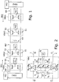
- Fig. 1 shows a power supply device with a two-pole bus line L , which is divided into bus segments BS by bus coupling elements (consumer bus coupling elements VBA1, ..., VBAn and feed bus coupling elements SBA1, SBA2 ).
- the bus line L can be interrupted (segmented into bus segments BS ) via switching elements S1 .
- the power bus here has a linear topology, for example, and is supplied with power from both sides of the power bus by a supply PS1, PS2 .
- the power bus is then preferably started up from the two supplies PS1, PS2 in sequence directions SR1, SR2 simultaneously from both sides of the power bus sequentially according to the method according to the invention described below.
- the first consumer bus coupling element VBA1 is directly connected to the first supply PS1 via the infeed bus coupling element SBA1 and the nth (last) consumer bus coupling element VBAn is directly connected to the further supply PS2 via a further infeed bus coupling element SBA2.
- the relevant bus segment BS' can be isolated by putting the neighboring consumer bus coupling elements (here: consumer bus coupling elements VBA2, VBA3) into the first operating state (see below) by opening the switching elements S1 ) to be brought.
- Consumers FE1, FE2 which are located on the consumer bus coupling elements VBA1, VBA2, which are located on the left of the disturbed bus segment BS ', can then use the first supply PS1, the consumers FE3 ... FEn which are located on the right of the disturbed bus segment BS' , are supplied via the further PS2 supply.
- switched-mode power supplies sometimes have very high input capacitances, which cause large inrush currents (rush-in currents).
- the current transients in turn lead to voltage drops on the power bus. Sequencing enables inrush current peaks to be avoided when an entire network of payloads (consumers) is switched on simultaneously.
- the loads and the bus segments are sequentially checked for faults during the bus setup and are connected to the power bus.
- a consumer bus coupling element VBA which enables the method according to the invention and thus the isolation of a disturbed bus segment and the (new) construction of the energy bus with an isolated bus segment, is shown in Fig. 2 shown.
- the consumer bus coupling element VBA comprises, in addition to the first switching element pair with the first switching elements S1 , a second switching element pair with second switching elements S2 , diodes and a control processor KP .
- the diodes are used to connect the control processor KP and a consumer FE to the bus line L.
- the control processor KP is connected in parallel to the test bridge branch PZ and is fed on one or both sides by the bus line L via the diodes. He switches on the consumer FE according to a certain predetermined criterion. This in Fig.
- the consumer bus coupling element VBA shown is in the basic state (switching elements S1, S2 are open).
- the consumer FE can be switched on by means of the second switching element S2 (first operating state).
- the bus line L is connected through (preferably after a time delay after closing the second switching elements S2) (second operating state).
- the first bus segment VBA1 in sequence direction SR1 is checked for faults.
- the bus coupling element preceding the bus segment serves as a reference bus coupling element for checking a bus segment. If the first bus segment is checked, the infeed bus coupling element serves as the reference bus coupling element RBA (SBA / RBA s. Fig. 7 ).
- RBA reference bus coupling element
- the voltage across the bridging resistors Due to the voltage drop across the bridging resistors, the voltage across the bridging resistors (test voltage) and thus on the control processor KP is lower than the minimum supply voltage during the testing process.
- the bridge voltages U +, U- or UR +, U R - measured by means of the bridge circuit ; U L +, U L - (depending on the direction of the sequence)
- any faults that may be present can be determined.
- the bus segment to be checked is supplied with energy at low resistance by closing the first switching elements S1 of the reference bus coupling element RBA.
- the first consumer bus coupling element VBA1 has an operating voltage which (due to voltage losses along the bus line) is generally lower than the supply voltage (typically 500 ... 900 VDC).
- the exceeding of the minimum operating voltage is then recognized and the consumer FE1 is switched on by closing the second switching element S2 of the first consumer bus coupling element VBA1 via a soft start.
- the next bus segment is checked.
- sequence direction SR1 one bus segment after the other is now checked completely autonomously and (if there is no fault) connected. At the same time and independently of this, this process can take place starting from the second feed PS2 in the sequence direction SR2. If a fault (eg short circuit) is detected in a bus segment BS ', the corresponding bus segment BS' is not switched on.
- a partial bus is then built up from each side (in each case from the supply PS1, PS2 to the disturbed bus segment BS ') so that the disturbed bus segment BS' remains isolated.
- the power bus and the consumers FE1, ... FEn connected to it can continue to be operated.
- This sequential check and connection of bus segments can be carried out when the bus is initially set up or after consumers have been switched off due to a short circuit during operation of the energy bus, as described below:
- the maximum possible current of the supplies PS1, PS2 and the supplies PS1, PS2 usually reduce the voltage in order to limit the current.
- the currents are usually actively limited and no fuses are used on the feed side of the feed voltage. The occurrence of a short circuit thus leads to a considerable voltage reduction, which leads to the connected loads being switched off by opening the second switching element S2 (undervoltage detection by the control processor KP).
- the energy supply device according to the invention preferably has local energy stores E in the consumers, which can maintain the entire operation for a few minutes.
- the method according to the invention works completely without a higher-level configuration and control and enables a safe and fast bus structure, especially during operation of the energy bus, without consumers having to be switched off, so that the functionality of the energy bus can also function after a bus segment BS is lost (unusable) due to a short circuit can be guaranteed.
- the consumer bus coupling elements VBA are designed so that the fault test can be carried out using a double Wheatstone bridge circuit.
- the consumer bus coupling elements VBA include three bridge resistors R B , which are connected in series with one another between the positive potential side and the negative potential side of the bus line L, and two bridging resistors R S , which each bridge a switching element S1 of the first switching element pair.
- Fig. 3 shows on the left a section of a first embodiment of a power supply device according to the invention with an infeed bus coupling element SBA and two consumer bus coupling elements VBA1, VBA2, which limit the bus segment BS to be checked.
- the consumer bus coupling element VBA1 which is closer to the infeed bus coupling element SBA (in the direction of the arrow, which represents the direction of the bus setup sequence), is used in the inventive check of the bus segment BS (selected here as an example) as a reference bus coupling element RBA that is removed from the infeed bus coupling element SBA located consumer bus coupling element serves as a test bus coupling element PBA .
- Components of the two consumer bus coupling elements RBA, PBA and the bus segment to be checked form the double bridge circuit required for the method according to the invention, which is shown in FIG Fig. 3 shown on the right.
- the bridge resistors R B (hatched) of the reference bus coupling element RBA form a reference bridge branch RZ and the bridge resistors R B (checked) of the test bus coupling element PBA together with the bridging resistors R S (dotted) of the reference bus coupling element RBA form a test bridge branch PZ .
- the bridge resistances R B of a certain consumer bus coupling element can be part of the test bridge branch PZ or the reference bridge branch RZ of the bridge circuit, depending on whether the bus segment preceding or following the respective consumer bus coupling element is to be checked.
- the consumer bus coupling element VBA1 can also be used as a test bus coupling element for testing the from the infeed bus coupling element SBA1 and the consumer bus coupling element VBA1 are used for limited bus segments.
- An indicator bridge branch IZ to the bus line L goes off between the outer bridge resistances and the middle bridge resistance.
- Each indicator bridge branch IZ comprises a voltage measuring device V.
- the in Fig. 2 and Fig. 3 The consumer bus coupling elements shown are each shown on both sides (in the direction along the bus line L) indicator bridge branches IZ each to the positive and negative potential side of the bus line L; this enables the test according to the invention to be carried out from both sequence directions SR1, SR2.
- the indicator bridge branches IZ are Bridge voltages U +, U-, measured. Using this high-impedance, potential-free voltage measurement, all relevant states of the bus line L can be recorded.
- the failure to differentiate between “open line” and “connection” is not critical here, because the method according to the invention is intended to prevent interference caused by connecting a “bad” line.
- the line status "Line open or connection of the line” is not rated as a fault. If the state “line open or connection of the line” is determined, the first switching elements S1 of the reference bus coupling element RBA are closed anyway. In the case of a merger the energy bus is then connected through (fully assembled). In the event of an open line, the sequencing stops automatically and the power bus can be set up (provided that both sides are fed in) from the other side to the disturbed point.
- the separate central diagnostic unit is responsible for checking whether all consumers are being supplied by the power bus.
- Fig. 4 the corresponding faults in the power bus are shown in the marked area (top left: earth fault + pole->earth; bottom left: earth fault - pole->earth; right short circuit between bus lines).
- R B For the values of the bridge resistances R B , R and for the values of the bridging resistances R S were assumed to be 3R.
- a ground in the infeed bus coupling element SBA serves as the reference potential.
- the reference potential to earth becomes imprecise over the distance.
- Fig. 6 therefore shows a section of a further embodiment of an energy supply device according to the invention with a temporary reference potential in the reference bridge branch RZ. This is achieved by dividing the middle bridge resistance and providing a further switching element S3 with which a ground connection can be established from the division point of the middle bridge resistance. If a consumer bus coupling element is used as the reference bus coupling element RBA, the further switching element S3 is closed and the temporary reference potential is thus generated. However, because of the regulations for insulation monitoring and the required high insulation values, this connection should not exist continuously during operation, so that the further switching element S3 is opened as soon as the corresponding Consumer bus coupling element is no longer used as a reference bus coupling element RBA.
- Fig. 7 a section of the energy supply device according to the invention is shown (control processor and supply have been omitted from the illustration for the sake of clarity), in which the structure of the infeed bus coupling element SBA used for the energy supply device according to the invention is shown.
- the infeed bus coupling element SBA can serve as a reference bus coupling element RBA for checking the first bus segment VBA1 (in the direction of the arrow).
- the bus segments can also be checked on both sides (in both sequence directions SR1, SR2).
- the infeed bus coupling element SBA ' must be compared to the in Fig. 7 embodiment shown by further first switching elements S1 ' , which are independent of the first switching elements S1, bridging resistors R' S and voltage measuring devices V 'are expanded, as in Fig. 8 shown.
- the in Fig. 8 In addition, the mean bridge resistance R B is divided and can be used to balance the voltage in the IT network at the same time.
- an insulation measurement (which, for example, is normatively prescribed for the IT network type of the control and safety technology) can be carried out in addition to the above-described sequential check of the individual bus segments using the bridge circuit.
- These insulation measurements are carried out at the feed point with certified, industrial insulation monitoring devices.
- the insulation monitoring is carried out via a supply sector (between two feed points) with the help of a higher-level diagnostic unit, which is responsible for locating the bus line at suitable points to perform the insulation measurements.
- each bus segment can be electrically isolated between the consumer bus coupling elements VBA during operation.
- the diagnostic unit carries out the standardized quantitative insulation measurement at regular intervals. For this purpose, the diagnostic unit switches a separation point to the fully operational supply sector, which is fed from both sides, starting from the location of the active insulation monitoring device. After each measurement, the separation point is switched to another bus segment. The earth fault can be localized by switching the separation point of the power bus. This procedure gives an overview of the insulation conditions over the entire supply sector with a local resolution of a segment.
- the diagnostic unit regularly calls up operating data from the operating processors of the consumer bus coupling elements. As a result, the accessibility of the consumer bus coupling elements is checked and a stop of the autonomous sequential connection due to an error in the segment to be connected again is recognized.
Landscapes
- Physics & Mathematics (AREA)
- General Physics & Mathematics (AREA)
- Engineering & Computer Science (AREA)
- Power Engineering (AREA)
- Testing Of Short-Circuits, Discontinuities, Leakage, Or Incorrect Line Connections (AREA)
- Supply And Distribution Of Alternating Current (AREA)
Claims (18)
- Dispositif d'alimentation en énergie conçu pour alimenter en énergie des appareils consommateurs, comprenant• un bus de puissance, muni d'une ligne de bus (L) à 2 pôles,• des éléments (SBA, SBA1, SBA2, VBA, VBA1, ..., VBAn) de couplage de bus, sachant que deux éléments de couplage de bus délimitent un segment de bus de ladite ligne de bus (L) devant être contrôlé, et sachant que lesdits éléments (SBA, SBA1, SBA2, VBA, VBA1, ..., VBAn) de couplage de bus incluent, à chaque fois, une première paire d'éléments de commutation dotée de premiers éléments de commutation (S1) affectés au sectionnement électrique de ladite ligne de bus (L), et• un premier approvisionnement (PS1), en particulier une source de tension continue,caractérisé
par le fait que les éléments (SBA, SBA1, SBA2, VBA, VBA1, ..., VBAn) de couplage de bus incluent, à chaque fois, trois résistances de pont (RB) branchées mutuellement en série entre un côté potentiel positif et un côté potentiel négatif de la ligne de bus (L), et deux résistances de pontage (RS) respectivement montées en dérivation d'un élément de commutation (S1) de la première paire d'éléments de commutation ;
par le fait que ledit dispositif d'alimentation en énergie présente, en vue de spécifier des perturbations de ligne, un branchement en double pont de Wheatstone comportant une branche de pont de référence (RZ), une branche de pont de test (PZ) et deux branches de pont d'indication (IZ) ; et
par le fait que, pour contrôler le segment de bus (BS), l'un des éléments (SBA, SBA1, SBA2, VBA, VBA1, ..., VBAn) de couplage de bus, délimitant ledit segment de bus à contrôler, remplit une fonction d'élément de couplage de bus de référence (RBA), et l'autre, une fonction d'élément de couplage de bus de test (PBA), sachant que la branche de pont de référence (RZ) inclut les trois résistances de pont (RB) dudit élément de couplage de bus de référence (RBA), et sachant que la branche de pont de test (PZ) inclut les trois résistances de pont (RB) dudit élément de couplage de bus de test (PBA), ainsi que les résistances de pontage (RS) dudit élément de couplage de bus de référence (RBA). - Dispositif selon la revendication 1, caractérisé par le fait que les appareils consommateurs (FE) sont équipés, au moins en partie, d'un accumulateur local d'énergie (E).
- Dispositif selon l'une des revendications précédentes, caractérisé par le fait que la ligne de bus (L) est connectée électriquement à un approvisionnement additionnel (PS2).
- Dispositif selon l'une des revendications précédentes, caractérisé par le fait que la résistance de pont médiane, au sein des résistances de pont (RB) branchées en série, présente une plus grande valeur résistive que les deux résistances de pont extérieures, en particulier d'un facteur de 1,2 à 1,5.
- Dispositif selon l'une des revendications précédentes, caractérisé par la présence d'un appareil de surveillance d'isolement, dédié à l'exécution de mesures d'isolement sur des segments de bus (BS) et/ou sur les éléments individuels (VBA, VBA1, .., VBAn) de couplage de bus, et d'une unité de diagnostic conçue pour commander lesdites mesures d'isolement.
- Dispositif selon l'une des revendications précédentes, caractérisé par le fait qu'au moins un appareil consommateur (FE) est connecté à l'un des éléments (VBA, VBA1, ..., VBAn) de couplage de bus, les appareils consommateurs (FE) se présentant, de préférence, comme des composants de la technologie de contrôle et de commande, en particulier comme des éléments de terrain, lesdits appareils consommateurs (FE) incluant, à chaque fois, une logique et un processeur d'exploitation.
- Procédé d'actionnement d'un dispositif d'alimentation en énergie conforme à l'une des revendications précédentes, ledit procédé incluant les étapes opératoires suivantes, consistant à :a) sélectionner un segment de bus à contrôler, sachant qu'une tension de service est appliquée à l'élément de couplage de bus de référence (RBA) dudit segment de bus à contrôler, et sachant que les premiers éléments de commutation (S1) dudit élément de couplage de bus de référence (RBA) du segment de bus à contrôler sont ouverts de telle sorte qu'une tension de test, réduite par rapport à ladite tension de service, soit appliquée à l'élément de couplage de bus de test (PBA) ;b) mesurer une première tension de pont et une seconde tension de pont du branchement en double pont de Wheatstone ;c) contrôler, en fonction des tensions de pont mesurées, si une perturbation se présente ;d) en l'absence de perturbation :l'élément de couplage de bus de test (PBA) est mis en circuit avec le bus de puissance, par fermeture des éléments de commutation (S1) de la première paire d'éléments de commutation de l'élément de couplage de bus de référence (RBA), etles étapes a) - d) sont réitérées, un segment de bus (BS) successif étant alors sélectionné pour constituer le segment de bus à contrôler ;e) en présence d'une perturbation, le procédé est arrêté de telle sorte que l'élément de couplage de bus de test (PBA) ne soit pas mis en circuit avec le bus de puissance, et qu'il ne s'opère aucun contrôle de segments de bus (BS) supplémentaires.
- Procédé selon la revendication 7, caractérisé par le fait qu'une perturbation est constatée, à l'étape c), lorsquei. la première tension de pont et la seconde tension de pont excèdent une valeur limite positive, ouii. ladite première tension de pont et ladite seconde tension de pont se situent en deçà d'une valeur limite négative, ouiii. lorsque ladite première tension de pont se situe en deçà d'une valeur limite négative, et ladite seconde tension de pont excède une valeur limite positive.
- Procédé selon la revendication 7 ou 8, caractérisé par le fait que ledit procédé est utilisé pour démarrer le bus de puissance, la mise en circuit des éléments (VBA, VBA1, ..., VBAn) de couplage de bus ayant lieu séquentiellement à partir de l'approvisionnement.
- Procédé selon l'une des revendications 7 à 9, caractérisé par le fait que ledit procédé est utilisé, au cours du fonctionnement du bus de puissance, après constatation d'une perturbation en service, d'un court-circuit en particulier, et d'un isolement du segment de bus concerné par ladite perturbation en service dans ledit bus de puissance.
- Procédé selon la revendication 10, caractérisé par le fait que la perturbation en service est détectée par détection d'une sous-tension sur un ou plusieurs élément(s) (VBA) de couplage de bus d'appareil(s) consommateur(s),
que, dans les éléments (VBA) de couplage de bus d'appareils consommateurs dans lesquels ladite sous-tension a été détectée, l'appareil consommateur (FE) est déconnecté automatiquement d'avec le bus de puissance par ouverture des deuxièmes éléments de commutation (S2), et
que l'isolement du segment de bus (BS') concerné par ladite perturbation en service s'opère automatiquement, par ouverture des premiers éléments de commutation (S1). - Procédé selon la revendication 10 ou 11, caractérisé par le fait que les appareils consommateurs (FE) sont alimentés en énergie, au cours du procédé de configuration du bus, par l'intermédiaire d'accumulateurs locaux d'énergie (E).
- Procédé selon l'une des revendications 7 à 12, caractérisé par le fait qu'un segment de bus (BS), voisin du segment de bus à contrôler préalablement sélectionné, est sélectionné à l'étape d) en tant que segment de bus à contrôler.
- Procédé selon l'une des revendications 7 à 13, caractérisé par le fait qu'un potentiel local de référence par rapport à la terre est commuté temporairement dans la branche de pont de référence (RZ), de préférence en scindant la résistance de pont médiane en deux éléments de résistance de pont et en connectant, entre ces éléments de résistance de pont, un élément de commutation supplémentaire (S3) au potentiel de terre.
- Procédé selon l'une des revendications 7 à 14, caractérisé par le fait que le bus de puissance est alimenté en énergie des deux côtés.
- Procédé selon la revendication 15, caractérisé par le fait que les étapes a) - e) sont exécutées en simultanéité pour un segment de bus supplémentaire à contrôler, la tension de test étant appliquée au segment de bus à contrôler, et audit segment de bus supplémentaire à contrôler, à partir de directions différentes à l'intérieur du bus de puissance.
- Procédé selon la revendication 16, caractérisé par le fait que l'alimentation du segment de bus supplémentaire à contrôler, par la tension de test, a lieu au moyen d'un second approvisionnement (PS2).
- Procédé selon l'une des revendications 7 à 17, caractérisé par le fait que, durant le fonctionnement du bus de puissance, des mesures d'isolement sont effectuées, au moyen d'un appareil de surveillance d'isolement, sur des tronçons de la ligne de bus (L) qui sont commandés à distance au moyen d'une unité de diagnostic, des appareils consommateurs (FE) demeurant en service à l'intérieur de ce tronçon de ligne.
Priority Applications (4)
| Application Number | Priority Date | Filing Date | Title |
|---|---|---|---|
| EP18158615.7A EP3531137B1 (fr) | 2018-02-26 | 2018-02-26 | Dispositif d'alimentation en énergie et procédé de fonctionnement d'un dispositif d'alimentation en énergie |
| ES18158615T ES2833470T3 (es) | 2018-02-26 | 2018-02-26 | Dispositivo de suministro de energía y procedimiento para operar un dispositivo de suministro de energía |
| PT181586157T PT3531137T (pt) | 2018-02-26 | 2018-02-26 | Dispositivo de alimentação de energia eléctrica e procedimento para operação do mesmo |
| DK18158615.7T DK3531137T3 (da) | 2018-02-26 | 2018-02-26 | Energiforsyningsapparat samt fremgangsmåde til drift af et energiforsyningsapparat |
Applications Claiming Priority (1)
| Application Number | Priority Date | Filing Date | Title |
|---|---|---|---|
| EP18158615.7A EP3531137B1 (fr) | 2018-02-26 | 2018-02-26 | Dispositif d'alimentation en énergie et procédé de fonctionnement d'un dispositif d'alimentation en énergie |
Publications (2)
| Publication Number | Publication Date |
|---|---|
| EP3531137A1 EP3531137A1 (fr) | 2019-08-28 |
| EP3531137B1 true EP3531137B1 (fr) | 2020-10-28 |
Family
ID=61386728
Family Applications (1)
| Application Number | Title | Priority Date | Filing Date |
|---|---|---|---|
| EP18158615.7A Active EP3531137B1 (fr) | 2018-02-26 | 2018-02-26 | Dispositif d'alimentation en énergie et procédé de fonctionnement d'un dispositif d'alimentation en énergie |
Country Status (4)
| Country | Link |
|---|---|
| EP (1) | EP3531137B1 (fr) |
| DK (1) | DK3531137T3 (fr) |
| ES (1) | ES2833470T3 (fr) |
| PT (1) | PT3531137T (fr) |
Families Citing this family (1)
| Publication number | Priority date | Publication date | Assignee | Title |
|---|---|---|---|---|
| DE102022206731A1 (de) * | 2022-06-30 | 2024-01-04 | Gts Deutschland Gmbh | Schutzvorrichtung zum schutz einer elektrischen gleisfeld-infrastruktur, gleisfeld-energieversorgungseinrichtung und verfahren zur begrenzung von potentialverschiebungen in einer elektrischen gleisfeld-infrastruktur |
Family Cites Families (3)
| Publication number | Priority date | Publication date | Assignee | Title |
|---|---|---|---|---|
| DE102010030821A1 (de) * | 2010-07-01 | 2012-01-05 | Endress + Hauser Process Solutions Ag | Verfahren und Vorrichtung zur Inbetriebnahme von Feldgeräten, insbesondere von HART-Feldgeräten im Multidrop-Betriebsmodus |
| EP3109128A1 (fr) | 2015-06-25 | 2016-12-28 | Siemens Schweiz AG | Système et procédé d'élimination de court-circuit dans un bus d'alimentation |
| PT3247015T (pt) | 2016-05-18 | 2020-01-27 | Thales Man & Services Deutschland Gmbh | Dispositivo de abastecimento de corrente e processo para a operação de um dispositivo de abastecimento de corrente |
-
2018
- 2018-02-26 DK DK18158615.7T patent/DK3531137T3/da active
- 2018-02-26 PT PT181586157T patent/PT3531137T/pt unknown
- 2018-02-26 ES ES18158615T patent/ES2833470T3/es active Active
- 2018-02-26 EP EP18158615.7A patent/EP3531137B1/fr active Active
Non-Patent Citations (1)
| Title |
|---|
| None * |
Also Published As
| Publication number | Publication date |
|---|---|
| DK3531137T3 (da) | 2020-11-30 |
| PT3531137T (pt) | 2020-11-25 |
| ES2833470T3 (es) | 2021-06-15 |
| EP3531137A1 (fr) | 2019-08-28 |
Similar Documents
| Publication | Publication Date | Title |
|---|---|---|
| DE3886690T2 (de) | Gleichstromleistungsversorgung mit einem Hauptregler und Nebenreglern. | |
| DE102019112706A1 (de) | Verfahren und Vorrichtung zur Energieversorgung eines elektrischen Verbrauchers eines Fahrzeugs | |
| DE112010000698T5 (de) | Elektrischer Schaltkreis mit redundanter Verbindungsleitung | |
| DE102015107622A1 (de) | Motorantriebsvorrichtung , umfassend Funktion zur Fehlererfassung im Wechselrichter und in der Stromleitung | |
| EP3109128A1 (fr) | Système et procédé d'élimination de court-circuit dans un bus d'alimentation | |
| WO2020035296A1 (fr) | Ensemble de conversion ca/cc électrique | |
| EP4354803A2 (fr) | Procédé et circuit pour faire fonctionner un réseau ou une section de réseau | |
| EP3501100B1 (fr) | Dispositif de séparation pour une chaîne photovoltaïque | |
| EP3247015B1 (fr) | Dispositif d'alimentation electrique et procede de fonctionnement d'un dispositif d'alimentation electrique | |
| DE2453011A1 (de) | Verfahren und schaltungsanordnung zur auswahl eines signals aus wenigstens drei redundanten signalkanaelen | |
| DE102013209142A1 (de) | Verfahren zur Ermittlung eines Isolationswiderstands eines mehrere Teilnetze umfassenden Energieversorgungsnetzwerks eines Fahrzeugs | |
| EP2434358A1 (fr) | Procédé de fonctionnement d'un système redondant et système | |
| EP2546852A2 (fr) | Relais de sécurité bistable | |
| EP3531137B1 (fr) | Dispositif d'alimentation en énergie et procédé de fonctionnement d'un dispositif d'alimentation en énergie | |
| WO2020207730A1 (fr) | Localisation d'un défaut à la terre dans un réseau à tension continue | |
| EP3200033B1 (fr) | Systeme comprenant au moins deux unites peripheriques et un capteur | |
| DE102018206804A1 (de) | Erkennung von Unterbrechungen eines Stromkreises | |
| EP1190403B1 (fr) | Circuit pour enclencher et actionner des appareils connectes en serie dans une installation de commande et de transmission de donnees, en ce qui concerne leur tension d'alimentation | |
| WO2017140698A1 (fr) | Rupture de câble dans les systèmes modulaires | |
| DE102013113474B3 (de) | Verbindungseinrichtung, Verfahren zu deren Betrieb sowie Buskommunikationsvorrichtung | |
| DE102018113489B4 (de) | Einheit | |
| DE10213732B4 (de) | Verfahren für die elektrische Versorgung von elektrischen Lasten in einem Fahrzeug | |
| EP4163739B1 (fr) | Procédé de surveillance d'un agencement de commutation électrique | |
| DE102020210339B4 (de) | Schaltungsanordnung und Verfahren zur Fehlererkennung | |
| DE102023206292A1 (de) | LLC-Resonanzwandleranordnung |
Legal Events
| Date | Code | Title | Description |
|---|---|---|---|
| PUAI | Public reference made under article 153(3) epc to a published international application that has entered the european phase |
Free format text: ORIGINAL CODE: 0009012 |
|
| STAA | Information on the status of an ep patent application or granted ep patent |
Free format text: STATUS: THE APPLICATION HAS BEEN PUBLISHED |
|
| AK | Designated contracting states |
Kind code of ref document: A1 Designated state(s): AL AT BE BG CH CY CZ DE DK EE ES FI FR GB GR HR HU IE IS IT LI LT LU LV MC MK MT NL NO PL PT RO RS SE SI SK SM TR |
|
| AX | Request for extension of the european patent |
Extension state: BA ME |
|
| STAA | Information on the status of an ep patent application or granted ep patent |
Free format text: STATUS: REQUEST FOR EXAMINATION WAS MADE |
|
| 17P | Request for examination filed |
Effective date: 20200122 |
|
| RBV | Designated contracting states (corrected) |
Designated state(s): AL AT BE BG CH CY CZ DE DK EE ES FI FR GB GR HR HU IE IS IT LI LT LU LV MC MK MT NL NO PL PT RO RS SE SI SK SM TR |
|
| GRAP | Despatch of communication of intention to grant a patent |
Free format text: ORIGINAL CODE: EPIDOSNIGR1 |
|
| STAA | Information on the status of an ep patent application or granted ep patent |
Free format text: STATUS: GRANT OF PATENT IS INTENDED |
|
| RIC1 | Information provided on ipc code assigned before grant |
Ipc: H02J 1/06 20060101ALI20200513BHEP Ipc: G01R 17/10 20060101AFI20200513BHEP |
|
| INTG | Intention to grant announced |
Effective date: 20200527 |
|
| GRAS | Grant fee paid |
Free format text: ORIGINAL CODE: EPIDOSNIGR3 |
|
| GRAA | (expected) grant |
Free format text: ORIGINAL CODE: 0009210 |
|
| STAA | Information on the status of an ep patent application or granted ep patent |
Free format text: STATUS: THE PATENT HAS BEEN GRANTED |
|
| AK | Designated contracting states |
Kind code of ref document: B1 Designated state(s): AL AT BE BG CH CY CZ DE DK EE ES FI FR GB GR HR HU IE IS IT LI LT LU LV MC MK MT NL NO PL PT RO RS SE SI SK SM TR |
|
| REG | Reference to a national code |
Ref country code: GB Ref legal event code: FG4D Free format text: NOT ENGLISH |
|
| REG | Reference to a national code |
Ref country code: CH Ref legal event code: EP |
|
| REG | Reference to a national code |
Ref country code: RO Ref legal event code: EPE |
|
| REG | Reference to a national code |
Ref country code: CH Ref legal event code: NV Representative=s name: VALIPAT S.A. C/O BOVARD SA NEUCHATEL, CH |
|
| REG | Reference to a national code |
Ref country code: AT Ref legal event code: REF Ref document number: 1328735 Country of ref document: AT Kind code of ref document: T Effective date: 20201115 |
|
| REG | Reference to a national code |
Ref country code: FI Ref legal event code: FGE |
|
| REG | Reference to a national code |
Ref country code: DE Ref legal event code: R096 Ref document number: 502018002820 Country of ref document: DE |
|
| REG | Reference to a national code |
Ref country code: PT Ref legal event code: SC4A Ref document number: 3531137 Country of ref document: PT Date of ref document: 20201125 Kind code of ref document: T Free format text: AVAILABILITY OF NATIONAL TRANSLATION Effective date: 20201119 Ref country code: IE Ref legal event code: FG4D Free format text: LANGUAGE OF EP DOCUMENT: GERMAN |
|
| REG | Reference to a national code |
Ref country code: DK Ref legal event code: T3 Effective date: 20201124 |
|
| REG | Reference to a national code |
Ref country code: SE Ref legal event code: TRGR |
|
| REG | Reference to a national code |
Ref country code: NL Ref legal event code: FP |
|
| REG | Reference to a national code |
Ref country code: NO Ref legal event code: T2 Effective date: 20201028 |
|
| PG25 | Lapsed in a contracting state [announced via postgrant information from national office to epo] |
Ref country code: GR Free format text: LAPSE BECAUSE OF FAILURE TO SUBMIT A TRANSLATION OF THE DESCRIPTION OR TO PAY THE FEE WITHIN THE PRESCRIBED TIME-LIMIT Effective date: 20210129 Ref country code: RS Free format text: LAPSE BECAUSE OF FAILURE TO SUBMIT A TRANSLATION OF THE DESCRIPTION OR TO PAY THE FEE WITHIN THE PRESCRIBED TIME-LIMIT Effective date: 20201028 |
|
| REG | Reference to a national code |
Ref country code: LT Ref legal event code: MG4D |
|
| PG25 | Lapsed in a contracting state [announced via postgrant information from national office to epo] |
Ref country code: IS Free format text: LAPSE BECAUSE OF FAILURE TO SUBMIT A TRANSLATION OF THE DESCRIPTION OR TO PAY THE FEE WITHIN THE PRESCRIBED TIME-LIMIT Effective date: 20210228 Ref country code: LV Free format text: LAPSE BECAUSE OF FAILURE TO SUBMIT A TRANSLATION OF THE DESCRIPTION OR TO PAY THE FEE WITHIN THE PRESCRIBED TIME-LIMIT Effective date: 20201028 Ref country code: BG Free format text: LAPSE BECAUSE OF FAILURE TO SUBMIT A TRANSLATION OF THE DESCRIPTION OR TO PAY THE FEE WITHIN THE PRESCRIBED TIME-LIMIT Effective date: 20210128 |
|
| REG | Reference to a national code |
Ref country code: ES Ref legal event code: FG2A Ref document number: 2833470 Country of ref document: ES Kind code of ref document: T3 Effective date: 20210615 |
|
| PG25 | Lapsed in a contracting state [announced via postgrant information from national office to epo] |
Ref country code: HR Free format text: LAPSE BECAUSE OF FAILURE TO SUBMIT A TRANSLATION OF THE DESCRIPTION OR TO PAY THE FEE WITHIN THE PRESCRIBED TIME-LIMIT Effective date: 20201028 |
|
| REG | Reference to a national code |
Ref country code: DE Ref legal event code: R097 Ref document number: 502018002820 Country of ref document: DE |
|
| PG25 | Lapsed in a contracting state [announced via postgrant information from national office to epo] |
Ref country code: LT Free format text: LAPSE BECAUSE OF FAILURE TO SUBMIT A TRANSLATION OF THE DESCRIPTION OR TO PAY THE FEE WITHIN THE PRESCRIBED TIME-LIMIT Effective date: 20201028 Ref country code: CZ Free format text: LAPSE BECAUSE OF FAILURE TO SUBMIT A TRANSLATION OF THE DESCRIPTION OR TO PAY THE FEE WITHIN THE PRESCRIBED TIME-LIMIT Effective date: 20201028 Ref country code: EE Free format text: LAPSE BECAUSE OF FAILURE TO SUBMIT A TRANSLATION OF THE DESCRIPTION OR TO PAY THE FEE WITHIN THE PRESCRIBED TIME-LIMIT Effective date: 20201028 Ref country code: SM Free format text: LAPSE BECAUSE OF FAILURE TO SUBMIT A TRANSLATION OF THE DESCRIPTION OR TO PAY THE FEE WITHIN THE PRESCRIBED TIME-LIMIT Effective date: 20201028 Ref country code: SK Free format text: LAPSE BECAUSE OF FAILURE TO SUBMIT A TRANSLATION OF THE DESCRIPTION OR TO PAY THE FEE WITHIN THE PRESCRIBED TIME-LIMIT Effective date: 20201028 |
|
| PLBE | No opposition filed within time limit |
Free format text: ORIGINAL CODE: 0009261 |
|
| STAA | Information on the status of an ep patent application or granted ep patent |
Free format text: STATUS: NO OPPOSITION FILED WITHIN TIME LIMIT |
|
| PG25 | Lapsed in a contracting state [announced via postgrant information from national office to epo] |
Ref country code: MC Free format text: LAPSE BECAUSE OF FAILURE TO SUBMIT A TRANSLATION OF THE DESCRIPTION OR TO PAY THE FEE WITHIN THE PRESCRIBED TIME-LIMIT Effective date: 20201028 |
|
| 26N | No opposition filed |
Effective date: 20210729 |
|
| PG25 | Lapsed in a contracting state [announced via postgrant information from national office to epo] |
Ref country code: LU Free format text: LAPSE BECAUSE OF NON-PAYMENT OF DUE FEES Effective date: 20210226 Ref country code: AL Free format text: LAPSE BECAUSE OF FAILURE TO SUBMIT A TRANSLATION OF THE DESCRIPTION OR TO PAY THE FEE WITHIN THE PRESCRIBED TIME-LIMIT Effective date: 20201028 |
|
| PG25 | Lapsed in a contracting state [announced via postgrant information from national office to epo] |
Ref country code: SI Free format text: LAPSE BECAUSE OF FAILURE TO SUBMIT A TRANSLATION OF THE DESCRIPTION OR TO PAY THE FEE WITHIN THE PRESCRIBED TIME-LIMIT Effective date: 20201028 |
|
| PG25 | Lapsed in a contracting state [announced via postgrant information from national office to epo] |
Ref country code: IE Free format text: LAPSE BECAUSE OF NON-PAYMENT OF DUE FEES Effective date: 20210226 |
|
| PG25 | Lapsed in a contracting state [announced via postgrant information from national office to epo] |
Ref country code: IS Free format text: LAPSE BECAUSE OF FAILURE TO SUBMIT A TRANSLATION OF THE DESCRIPTION OR TO PAY THE FEE WITHIN THE PRESCRIBED TIME-LIMIT Effective date: 20210228 |
|
| PG25 | Lapsed in a contracting state [announced via postgrant information from national office to epo] |
Ref country code: CY Free format text: LAPSE BECAUSE OF FAILURE TO SUBMIT A TRANSLATION OF THE DESCRIPTION OR TO PAY THE FEE WITHIN THE PRESCRIBED TIME-LIMIT Effective date: 20201028 |
|
| PG25 | Lapsed in a contracting state [announced via postgrant information from national office to epo] |
Ref country code: HU Free format text: LAPSE BECAUSE OF FAILURE TO SUBMIT A TRANSLATION OF THE DESCRIPTION OR TO PAY THE FEE WITHIN THE PRESCRIBED TIME-LIMIT; INVALID AB INITIO Effective date: 20180226 |
|
| PG25 | Lapsed in a contracting state [announced via postgrant information from national office to epo] |
Ref country code: MK Free format text: LAPSE BECAUSE OF FAILURE TO SUBMIT A TRANSLATION OF THE DESCRIPTION OR TO PAY THE FEE WITHIN THE PRESCRIBED TIME-LIMIT Effective date: 20201028 |
|
| P01 | Opt-out of the competence of the unified patent court (upc) registered |
Free format text: CASE NUMBER: APP_35438/2024 Effective date: 20240613 |
|
| PG25 | Lapsed in a contracting state [announced via postgrant information from national office to epo] |
Ref country code: MT Free format text: LAPSE BECAUSE OF FAILURE TO SUBMIT A TRANSLATION OF THE DESCRIPTION OR TO PAY THE FEE WITHIN THE PRESCRIBED TIME-LIMIT Effective date: 20201028 |
|
| PGFP | Annual fee paid to national office [announced via postgrant information from national office to epo] |
Ref country code: PT Payment date: 20250221 Year of fee payment: 8 |
|
| PGFP | Annual fee paid to national office [announced via postgrant information from national office to epo] |
Ref country code: RO Payment date: 20250211 Year of fee payment: 8 |
|
| PGFP | Annual fee paid to national office [announced via postgrant information from national office to epo] |
Ref country code: CH Payment date: 20250301 Year of fee payment: 8 |
|
| PGFP | Annual fee paid to national office [announced via postgrant information from national office to epo] |
Ref country code: PL Payment date: 20250114 Year of fee payment: 8 |
|
| PG25 | Lapsed in a contracting state [announced via postgrant information from national office to epo] |
Ref country code: TR Free format text: LAPSE BECAUSE OF FAILURE TO SUBMIT A TRANSLATION OF THE DESCRIPTION OR TO PAY THE FEE WITHIN THE PRESCRIBED TIME-LIMIT Effective date: 20201028 |
|
| PGFP | Annual fee paid to national office [announced via postgrant information from national office to epo] |
Ref country code: NL Payment date: 20260116 Year of fee payment: 9 |
|
| REG | Reference to a national code |
Ref country code: CH Ref legal event code: U11 Free format text: ST27 STATUS EVENT CODE: U-0-0-U10-U11 (AS PROVIDED BY THE NATIONAL OFFICE) Effective date: 20260301 |
|
| PGFP | Annual fee paid to national office [announced via postgrant information from national office to epo] |
Ref country code: SE Payment date: 20260112 Year of fee payment: 9 |
|
| PGFP | Annual fee paid to national office [announced via postgrant information from national office to epo] |
Ref country code: GB Payment date: 20260119 Year of fee payment: 9 |
|
| PGFP | Annual fee paid to national office [announced via postgrant information from national office to epo] |
Ref country code: ES Payment date: 20260310 Year of fee payment: 9 |
|
| PGFP | Annual fee paid to national office [announced via postgrant information from national office to epo] |
Ref country code: NO Payment date: 20260211 Year of fee payment: 9 Ref country code: DE Payment date: 20260114 Year of fee payment: 9 Ref country code: DK Payment date: 20260213 Year of fee payment: 9 |
|
| PGFP | Annual fee paid to national office [announced via postgrant information from national office to epo] |
Ref country code: AT Payment date: 20260127 Year of fee payment: 9 |
|
| PGFP | Annual fee paid to national office [announced via postgrant information from national office to epo] |
Ref country code: BE Payment date: 20260113 Year of fee payment: 9 Ref country code: IT Payment date: 20260122 Year of fee payment: 9 Ref country code: FI Payment date: 20260213 Year of fee payment: 9 |
|
| PGFP | Annual fee paid to national office [announced via postgrant information from national office to epo] |
Ref country code: FR Payment date: 20260121 Year of fee payment: 9 |