EP3531220A1 - Feldgerät für ein automatisierungssystem - Google Patents
Feldgerät für ein automatisierungssystem Download PDFInfo
- Publication number
- EP3531220A1 EP3531220A1 EP18158857.5A EP18158857A EP3531220A1 EP 3531220 A1 EP3531220 A1 EP 3531220A1 EP 18158857 A EP18158857 A EP 18158857A EP 3531220 A1 EP3531220 A1 EP 3531220A1
- Authority
- EP
- European Patent Office
- Prior art keywords
- field device
- configuration
- unit
- signal
- arithmetic unit
- Prior art date
- Legal status (The legal status is an assumption and is not a legal conclusion. Google has not performed a legal analysis and makes no representation as to the accuracy of the status listed.)
- Granted
Links
Images
Classifications
-
- G—PHYSICS
- G05—CONTROLLING; REGULATING
- G05B—CONTROL OR REGULATING SYSTEMS IN GENERAL; FUNCTIONAL ELEMENTS OF SUCH SYSTEMS; MONITORING OR TESTING ARRANGEMENTS FOR SUCH SYSTEMS OR ELEMENTS
- G05B19/00—Program-control systems
- G05B19/02—Program-control systems electric
- G05B19/04—Program control other than numerical control, i.e. in sequence controllers or logic controllers
- G05B19/05—Programmable logic controllers, e.g. simulating logic interconnections of signals according to ladder diagrams or function charts
- G05B19/054—Input/output
-
- H—ELECTRICITY
- H04—ELECTRIC COMMUNICATION TECHNIQUE
- H04L—TRANSMISSION OF DIGITAL INFORMATION, e.g. TELEGRAPHIC COMMUNICATION
- H04L41/00—Arrangements for maintenance, administration or management of data switching networks, e.g. of packet switching networks
- H04L41/08—Configuration management of networks or network elements
- H04L41/0803—Configuration setting
- H04L41/0813—Configuration setting characterised by the conditions triggering a change of settings
-
- G—PHYSICS
- G05—CONTROLLING; REGULATING
- G05B—CONTROL OR REGULATING SYSTEMS IN GENERAL; FUNCTIONAL ELEMENTS OF SUCH SYSTEMS; MONITORING OR TESTING ARRANGEMENTS FOR SUCH SYSTEMS OR ELEMENTS
- G05B19/00—Program-control systems
- G05B19/02—Program-control systems electric
- G05B19/04—Program control other than numerical control, i.e. in sequence controllers or logic controllers
- G05B19/042—Program control other than numerical control, i.e. in sequence controllers or logic controllers using digital processors
-
- G—PHYSICS
- G05—CONTROLLING; REGULATING
- G05B—CONTROL OR REGULATING SYSTEMS IN GENERAL; FUNCTIONAL ELEMENTS OF SUCH SYSTEMS; MONITORING OR TESTING ARRANGEMENTS FOR SUCH SYSTEMS OR ELEMENTS
- G05B19/00—Program-control systems
- G05B19/02—Program-control systems electric
- G05B19/418—Total factory control, i.e. centrally controlling a plurality of machines, e.g. direct or distributed numerical control [DNC], flexible manufacturing systems [FMS], integrated manufacturing systems [IMS] or computer integrated manufacturing [CIM]
- G05B19/4185—Total factory control, i.e. centrally controlling a plurality of machines, e.g. direct or distributed numerical control [DNC], flexible manufacturing systems [FMS], integrated manufacturing systems [IMS] or computer integrated manufacturing [CIM] characterised by the network communication
- G05B19/4186—Total factory control, i.e. centrally controlling a plurality of machines, e.g. direct or distributed numerical control [DNC], flexible manufacturing systems [FMS], integrated manufacturing systems [IMS] or computer integrated manufacturing [CIM] characterised by the network communication by protocol, e.g. MAP, TOP
-
- H—ELECTRICITY
- H04—ELECTRIC COMMUNICATION TECHNIQUE
- H04L—TRANSMISSION OF DIGITAL INFORMATION, e.g. TELEGRAPHIC COMMUNICATION
- H04L41/00—Arrangements for maintenance, administration or management of data switching networks, e.g. of packet switching networks
- H04L41/08—Configuration management of networks or network elements
- H04L41/0866—Checking the configuration
- H04L41/0869—Validating the configuration within one network element
-
- H—ELECTRICITY
- H04—ELECTRIC COMMUNICATION TECHNIQUE
- H04L—TRANSMISSION OF DIGITAL INFORMATION, e.g. TELEGRAPHIC COMMUNICATION
- H04L41/00—Arrangements for maintenance, administration or management of data switching networks, e.g. of packet switching networks
- H04L41/28—Restricting access to network management systems or functions, e.g. using authorisation function to access network configuration
-
- H—ELECTRICITY
- H04—ELECTRIC COMMUNICATION TECHNIQUE
- H04L—TRANSMISSION OF DIGITAL INFORMATION, e.g. TELEGRAPHIC COMMUNICATION
- H04L63/00—Network architectures or network communication protocols for network security
- H04L63/08—Network architectures or network communication protocols for network security for authentication of entities
- H04L63/083—Network architectures or network communication protocols for network security for authentication of entities using passwords
-
- H—ELECTRICITY
- H04—ELECTRIC COMMUNICATION TECHNIQUE
- H04L—TRANSMISSION OF DIGITAL INFORMATION, e.g. TELEGRAPHIC COMMUNICATION
- H04L63/00—Network architectures or network communication protocols for network security
- H04L63/10—Network architectures or network communication protocols for network security for controlling access to devices or network resources
- H04L63/102—Entity profiles
-
- H—ELECTRICITY
- H04—ELECTRIC COMMUNICATION TECHNIQUE
- H04L—TRANSMISSION OF DIGITAL INFORMATION, e.g. TELEGRAPHIC COMMUNICATION
- H04L63/00—Network architectures or network communication protocols for network security
- H04L63/18—Network architectures or network communication protocols for network security using different networks or channels, e.g. using out of band channels
-
- H—ELECTRICITY
- H04—ELECTRIC COMMUNICATION TECHNIQUE
- H04L—TRANSMISSION OF DIGITAL INFORMATION, e.g. TELEGRAPHIC COMMUNICATION
- H04L67/00—Network arrangements or protocols for supporting network services or applications
- H04L67/01—Protocols
- H04L67/02—Protocols based on web technology, e.g. hypertext transfer protocol [HTTP]
-
- H—ELECTRICITY
- H04—ELECTRIC COMMUNICATION TECHNIQUE
- H04L—TRANSMISSION OF DIGITAL INFORMATION, e.g. TELEGRAPHIC COMMUNICATION
- H04L67/00—Network arrangements or protocols for supporting network services or applications
- H04L67/01—Protocols
- H04L67/02—Protocols based on web technology, e.g. hypertext transfer protocol [HTTP]
- H04L67/025—Protocols based on web technology, e.g. hypertext transfer protocol [HTTP] for remote control or remote monitoring of applications
-
- G—PHYSICS
- G05—CONTROLLING; REGULATING
- G05B—CONTROL OR REGULATING SYSTEMS IN GENERAL; FUNCTIONAL ELEMENTS OF SUCH SYSTEMS; MONITORING OR TESTING ARRANGEMENTS FOR SUCH SYSTEMS OR ELEMENTS
- G05B2219/00—Program-control systems
- G05B2219/20—Pc systems
- G05B2219/25—Pc structure of the system
- G05B2219/25428—Field device
-
- H—ELECTRICITY
- H04—ELECTRIC COMMUNICATION TECHNIQUE
- H04L—TRANSMISSION OF DIGITAL INFORMATION, e.g. TELEGRAPHIC COMMUNICATION
- H04L67/00—Network arrangements or protocols for supporting network services or applications
- H04L67/34—Network arrangements or protocols for supporting network services or applications involving the movement of software or configuration parameters
Definitions
- the invention relates to a field device for an automation system, which comprises a computing unit, a control element and a hardware interface.
- the arithmetic unit is configured to manage configuration data for operating the field device.
- the operating element is a user-operable operating element whose actuation can be detected by the arithmetic unit.
- the hardware interface allows the connection of the field device to a communication system of the automation system or a configuration unit.
- a field device of the type mentioned above is a technical device in the field of automation technology.
- the field device serves e.g. the control and / or monitoring and / or protection of a component in a production process or work process.
- the field device is connected either via a fieldbus or increasingly via a real-time Ethernet as a communication system with a control and management system, are evaluated in the data that is used to control, control and further processing of the field device or the associated Component can be used.
- the configuration takes place via an external configuration unit, which can access it via the communication system and the hardware interface of the field device.
- the hardware interface is designed to connect the field device to a fieldbus system, then it has only limited, local communication options.
- a technician For on-site configuration of the field device, a technician must have a Profinet connection (or other, from fieldbus supported serial data connection), which requires special software tools. These software tools may differ from field device to field device, making such a configuration inflexible. Alternatively, a programmable controller could be used, which, however, also a considerable effort is connected.
- the hardware interface is provided for connection to a real-time Ethernet communication system, an extended, standardized communication with the field device is possible.
- the design of the hardware interface as an Ethernet interface entails an increased risk potential for attacks. Provides e.g. an attacker access to the Ethernet-based communication system of the automation system, he can in the absence of further protection mechanisms readily access the computing unit of the field device and possibly delete configuration data for operation of the field device and / or change, which in the worst case, a normal operation of the field device is no longer possible.
- a field device for an automation system that includes a computing unit, a user-operable control element and a hardware interface includes.
- the arithmetic unit is configured to manage configuration data for operating the field device. An actuation of the operating element by a user can be detected by the arithmetic unit.
- the hardware interface is used to connect the field device to a communication system of the automation system or a configuration unit.
- the arithmetic unit is configured to put the field device in a configuration mode for changing the configuration data, if at the same time a first signal from the operating element, which represents an actuation by a user, and a second signal from the hardware interface, the connection of a wired Connection represents, be received.
- Such a designed field device allows the integration of a special on-site mode, which allows the change of the configuration data for operation of the field device by a user only at the location of the field device.
- the change of the configuration data is made possible by the arithmetic unit only when two conditions are met at the same time.
- the actuation of the control element by a user is required, on the other hand, the signaling of the connection of a wired connection is necessary. This is understood to mean the process of connecting a cable to the hardware interface.
- Both criteria require that the user perform the two acts at the location of the field device to allow the arithmetic unit to check these as criteria. An access or a change of the configuration data is thus only possible if the user has physical access to the field device. Regardless of the design of the hardware interface and / or the communication system and their respective protection mechanisms, a high security against manipulation can be ensured.
- the arithmetic unit executes a web server, by means of which the configuration data can be changed.
- the e. can communicate via a hardware-interface with the computing unit of the field device via a configuration unit in the form of a computer or tablet PC, can provide all the data required for configuration, input screens, etc.
- the field device thus does not need to have a proprietary display for changing the configuration data.
- the execution of the web server can be initiated by the field device via a wired connection, which is plugged into the hardware interface, connected to the configuration unit simultaneously actuate the control.
- the arithmetic unit can be set up to allow a change, in particular a write, of the configuration data in the configuration mode.
- the arithmetic unit is set up to query a password in the configuration mode before the authorization of a change.
- another password must be entered by the user as a further criterion in order to change the configuration data of the field device to be able to make using the executed by the computing unit of the field device web server.
- the web server can be reached by the configuration unit via a predetermined (fixed) address.
- the user In order to reach the web server, the user must therefore know the address of the web server.
- the web server can be reached via a dynamic assignment of a network configuration with name resolution from the configuration unit. This principle is known as DHCP (Dynamic Host Configuration Protocol).
- DHCP Dynamic Host Configuration Protocol
- an "alias" could also be implemented so that the user in the web server in the address line only has a name known to him, e.g. Must specify "ABCdevice".
- the first signal may include a predetermined content information and / or be present for a predetermined period of time.
- a predetermined content information can be used, for example, if the field device has a plurality of operating elements, wherein the actuation of a respective operating element represents a different information. If the field device has only one operating element or if a specific operating element has to be actuated to activate the configuration mode, this can be done e.g. be realized by pressing for a predetermined minimum period of time.
- the second signal results according to a further embodiment from the attachment of the wired connection to the hardware interface.
- known mechanisms of the recognition of respective plug-in components and the associated signaling protocols can be used.
- the hardware interface is an Ethernet interface based on the IP protocol.
- the arithmetic unit is set up to automatically enter the configuration mode after a predetermined period of time to end.
- the time span is expediently dimensioned such that all required for a configuration or configuration change activities can be completed safely.
- Automatic termination of the configuration mode after a predetermined period of time does not require the user to explicitly log off the web server or close the web server. This is associated with an increase in security against unauthorized access to the field device.
- a method for computer-aided configuration of a field device is proposed, wherein the field device is designed according to the manner described above and described below.
- the method includes the step of receiving a first signal from the actuator that represents an operation by a user.
- the method includes the further step of receiving a second signal from the hardware interface that represents the connection of a wired connection.
- the method comprises the step of converting the field device into a configuration mode in which the configuration data of the field device can be changed by a configuration unit when the first and the second signal are received simultaneously.
- the arithmetic unit executes a web server in the configuration mode.
- the web server is expediently started automatically when the arithmetic unit determines that the first and second signals have been received simultaneously.
- the arithmetic unit permits a change, in particular a write, of the configuration data.
- the writing or changing of the configuration data is expediently carried out with the aid of an external configuration unit which is connected to the field device via the wired connection and the hardware interface.
- the configuration unit may be a computer, such as a computer. a laptop, a tablet PC and the like.
- the web server is expediently reached by the configuration unit via a predetermined (fixed) address.
- the address of the web server must be known to the user.
- the web server can be reached by the configuration unit via a dynamic assignment of network configuration and name resolution. This can be assigned automatically via the known method DHCP, a network address.
- an "alias" may be implemented so that the user making the configuration in the address field of the web server only has a known alias name, e.g. Must enter "ABCdevice".
- the arithmetic unit determines whether the first signal comprises a predetermined content information or is applied for a predetermined period of time. Only in the presence of a respective criterion then represents the first signal actuation by a user.
- the arithmetic unit determines whether the second signal results from the attachment of the wired connection to the hardware interface. Only in this case, the second signal represents the connection of a wired connection and thus leads to a fulfillment of the criterion.
- a further embodiment provides that the arithmetic unit automatically terminates the configuration mode after a predetermined period of time. This will ensure that at a temporally ongoing connection of the configuration unit with the field device no later change to the configuration data can take place, which may not come from an authorized user.
- a computer program product which can be loaded directly into the internal memory of a digital arithmetic unit and includes software code sections with which the method described herein can be performed when the product is running on the arithmetic unit.
- the computer program product may be in the form of a CD-ROM, a DVD, a USB memory stick or a signal loadable via a wired or wireless network.
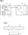
- Fig. 1 shows a field device 10 for a not-shown automation system.
- the field device 10 comprises a computing unit 11, an operating element 12, a hardware interface 13 and a memory 15.
- the memory 15 stores configuration data 16 which are processed by the computing unit 11 for operation of the field device 10.
- the field device 10 is used in a manner known to those skilled in the art for controlling and / or monitoring a component (not shown) of the automation system.
- the operating element 12 may be, for example, a button, a switch or another element which serves for the intended operation of the field device.
- the control element can be a reset button in order to be able to put the field device in an initial state at the request of a user.
- the field device 10 is connected via the hardware interface 13 to a not shown communication system of the automation system.
- the communication system can be designed, for example, as a real-time Ethernet.
- field device 10 may exchange data (e.g., measurement data, control data, and the like) with a control and guidance system or other field devices in a manner known to those skilled in the art.
- the changing of the configuration data 16 contained in the memory 15 takes place with the aid of a web server 14, which can be executed by the arithmetic unit 11.
- a web server 14 which can be executed by the arithmetic unit 11.
- two conditions must exist which require the physical proximity of a user to the field device 10.
- the operating element 12 is to be actuated by the user in a predefined manner; on the other hand, a wired connection, for example a network cable, is to be connected to the hardware interface 13.
- the actuation of the control element 12 in the predetermined manner leads to a first signal sig1, which is received by the arithmetic unit 11.
- connection of a network cable to the hardware interface 13 leads to a second signal sig2, which is also received by the interface 11. If the first and second signals sig1 and sig2 are simultaneously received by the arithmetic unit 11, the conditions for starting and executing the web server 14 are met.
- the web server 14 may be implemented, for example, by a configuration unit 20 in the form of a computer, e.g. Laptop or tablet PC, to be used.
- the configuration unit 20 has a display 21, an input means 22 (e.g., keyboard and / or touch-sensitive display and / or pointing device) and an interface 23 into which the other end of the network cable 30 representing the wired connection is plugged.
- Access to the web server 14 by the configuration unit 20 is either via a fixed address input by a user of the configuration unit 20 via the input means.
- a dynamic assignment of an address can be made via DHCP as soon as the physical connection is established by means of the wired connection 30 between the hardware interface 13 and the interface 23.
- access to the web server is, as described above, only possible if at the same time the operation of the operating element 12 by the user could be determined by the computing unit 11. For this purpose, as described, for example, it may be necessary for the operating element 12 to be in operation for a predetermined period of time, e.g. for several seconds, is pressed.
- a change of the configuration data 16 can take place by means of the configuration unit 20.
- the configuration data which are currently stored in the memory 15, can be first visualized on the display 21 and changed using the input unit 22, overwritten or deleted.
- the web server 14 can be automatically stopped by the arithmetic unit 11 when For example, after starting the web server a predetermined period of time, eg 10 minutes, has passed. This additionally makes it more difficult for potential attackers to manipulate the configuration data 16 in the field device 10.
- the two components can also be interconnected with the interposition of a router or other technical switching device.
- Fig. 2 shows the basic sequence of the method of the computer-aided configuration of the field device 10.
- a first signal sig1 is received by the operating element 12, which represents an actuation by a user.
- a second signal sig2 is received by the hardware interface 13, which represents the connection of a wired connection. If it is determined in a step S3 that the first and the second signal sig1, sig2 are simultaneously received by the arithmetic unit 11, the field device 10 is converted by the arithmetic unit 11 into a configuration mode, in which the configuration data 16 of the field device 10 by a to the Hardware interface 13 connected configuration unit 20 are changeable.
Landscapes
- Engineering & Computer Science (AREA)
- Computer Networks & Wireless Communication (AREA)
- Signal Processing (AREA)
- Computer Security & Cryptography (AREA)
- General Engineering & Computer Science (AREA)
- Computer Hardware Design (AREA)
- Computing Systems (AREA)
- Automation & Control Theory (AREA)
- General Physics & Mathematics (AREA)
- Physics & Mathematics (AREA)
- Manufacturing & Machinery (AREA)
- Quality & Reliability (AREA)
- Small-Scale Networks (AREA)
- Programmable Controllers (AREA)
Abstract
Description
- Die Erfindung betrifft ein Feldgerät für ein Automatisierungssystem, das eine Recheneinheit, ein Bedienelement und eine Hardware-Schnittstelle umfasst. Die Recheneinheit ist dazu eingerichtet, Konfigurationsdaten zum Betrieb des Feldgeräts zu verwalten. Das Bedienelement ist ein durch einen Nutzer betätigbares Bedienelement, dessen Betätigung durch die Recheneinheit erfassbar ist. Die Hardware-Schnittstelle ermöglicht den Anschluss des Feldgeräts an ein Kommunikationssystem des Automatisierungssystems oder eine Konfigurationseinheit.
- Ein Feldgerät der oben genannten Art ist eine technische Einrichtung im Bereich der Automatisierungstechnik. Das Feldgerät dient z.B. der Steuerung und/oder Überwachung und/oder dem Schutz einer Komponente in einem Produktionsprozess oder einem Arbeitsprozess. Über seine Hardware-Schnittstelle ist das Feldgerät entweder über einen Feldbus oder zunehmend auch über ein Echtzeit-Ethernet als Kommunikationssystem mit einem Steuerungs- und Leitsystem verbunden, in dem Daten ausgewertet werden, die zur Regelung, Steuerung und weiteren Verarbeitung des Feldgeräts bzw. der zugeordneten Komponente genutzt werden.
- Da nicht alle Feldgeräte über ein ausreichend großes Display verfügen, erfolgt die Konfiguration über eine externe Konfigurationseinheit, welche über das Kommunikationssystem und die Hardware-Schnittstelle des Feldgeräts auf dieses zugreifen kann.
- Ist die Hardware-Schnittstelle zum Anschluss des Feldgeräts an ein Feldbussystem ausgebildet, so verfügt diese über lediglich eingeschränkte, lokale Kommunikationsmöglichkeiten. Für eine Vor-Ort-Konfiguration des Feldgeräts muss durch einen Techniker eine Profinet-Verbindung (oder eine andere, von dem Feldbus unterstützte serielle Datenverbindung) aufgebaut werden, wofür spezielle Software-Tools erforderlich sind. Diese Software-Tools können sich dabei von Feldgerät zu Feldgerät unterscheiden, wodurch eine derartige Konfiguration unflexibel ist. Alternativ könnte eine speicherprogrammierbare Steuerung genutzt werden, womit jedoch ebenfalls ein nicht unerheblicher Aufwand verbunden ist.
- Ist die Hardware-Schnittstelle demgegenüber zum Anschluss an ein Echtzeit-Ethernet-Kommunikationssystem vorgesehen, so ist eine erweiterte, da standardisierte Kommunikation mit dem Feldgerät möglich. Die Ausgestaltung der Hardware-Schnittstelle als Ethernet-Schnittstelle bringt jedoch ein erhöhtes Gefährdungspotential für Angriffe mit sich. Verschafft sich z.B. ein Angreifer Zugriff auf das Ethernet-basierte Kommunikationssystem des Automatisierungssystems, so kann er beim Fehlen weiterer Schutzmechanismen ohne Weiteres auf die Recheneinheit des Feldgeräts zugreifen und ggf. Konfigurationsdaten zum Betrieb des Feldgeräts löschen und/oder verändern, wodurch im schlimmsten Fall ein bestimmungsgemäßer Betrieb des Feldgeräts nicht mehr möglich ist.
- Es ist daher Aufgabe der vorliegenden Erfindung, ein Feldgerät für ein Automatisierungssystem sowie ein Verfahren zum rechnergestützten Konfigurieren eines Feldgeräts für ein Automatisierungssystem anzugeben, welche eine einfache Vor-Ort-Konfiguration bei gleichzeitig hohem Sicherheitsstandard gegen unerlaubte Zugriffe bereitstellen.
- Diese Aufgaben werden gelöst durch ein Feldgerät gemäß den Merkmalen des Patentanspruchs 1 und ein Verfahren gemäß den Merkmalen des Patentanspruchs 11. Vorteilhafte Ausgestaltungen ergeben sich aus den jeweiligen abhängigen Patentansprüchen.
- Gemäß einem ersten Aspekt wird ein Feldgerät für ein Automatisierungssystem vorgeschlagen, das eine Recheneinheit, ein durch einen Nutzer betätigbares Bedienelement und eine Hardware-Schnittstelle umfasst. Die Recheneinheit ist dazu eingerichtet, Konfigurationsdaten zum Betrieb des Feldgeräts zu verwalten. Eine Betätigung des Bedienelements durch einen Nutzer ist durch die Recheneinheit erfassbar. Die Hardware-Schnittstelle dient zum Anschluss des Feldgeräts an ein Kommunikationssystem des Automatisierungssystems oder eine Konfigurationseinheit.
- Die Recheneinheit ist dazu eingerichtet, das Feldgerät zur Änderung der Konfigurationsdaten in einen Konfigurationsmodus zu versetzen, wenn gleichzeitig ein erstes Signal von dem Bedienelement, das eine Betätigung durch einen Nutzer repräsentiert, und ein zweites Signal von der Hardware-Schnittstelle, das den Anschluss einer drahtgebundenen Verbindung repräsentiert, empfangen werden.
- Ein derart ausgestaltetes Feldgerät ermöglicht die Integration eines speziellen Vor-Ort-Modus, der die Veränderung der Konfigurationsdaten zum Betrieb des Feldgeräts durch einen Nutzer nur am Ort des Feldgeräts ermöglicht. Die Änderung der Konfigurationsdaten wird durch die Recheneinheit dabei erst dann ermöglicht, wenn zwei Bedingungen zum gleichen Zeitpunkt erfüllt sind. Zum einen ist die Betätigung des Bedienelements durch einen Nutzer erforderlich, zum anderen ist die Signalisierung des Anschlusses einer drahtgebundenen Verbindung notwendig. Hierunter wird der Vorgang des Verbindens eines Kabels mit der Hardware-Schnittstelle verstanden. Beide Kriterien erfordern es, dass der Nutzer die beiden Handlungen am Ort des Feldgeräts durchführt, um es der Recheneinheit zu ermöglichen, diese als Kriterien zu überprüfen. Ein Zugriff bzw. eine Veränderung der Konfigurationsdaten ist somit nur möglich, wenn der Nutzer physikalischen Zugriff auf das Feldgerät hat. Unabhängig von der Ausgestaltung der Hardware-Schnittstelle und/oder des Kommunikationssystems und deren jeweiligen Schutzmechanismen kann dadurch eine hohe Sicherheit gegenüber Manipulation gewährleistet werden.
- Dadurch wird es ermöglicht, das Feldgerät derart auszugestalten, dass die Recheneinheit einen Webserver ausführt, durch den die Konfigurationsdaten geändert werden können. Auf diese Weise kann zur Änderung der Konfigurationsdaten auf spezielle Software-Tools verzichtet werden, da der Web-Server einem Nutzer, der z.B. über eine Konfigurationseinheit in Gestalt eines Rechners oder Tablet-PCs über die Hardware-Schnittstelle mit der Recheneinheit des Feldgeräts kommunizieren kann, sämtliche zur Konfiguration erforderlichen Daten, Eingabemasken usw. bereitstellen kann. Das Feldgerät braucht damit zur Änderung der Konfigurationsdaten über kein proprietäres Display zu verfügen. Die Ausführung des Webservers kann initiiert werden, indem das Feldgerät über eine drahtgebundene Verbindung, die in die Hardware-Schnittstelle eingesteckt wird, mit der Konfigurationseinheit verbunden gleichzeitig das Bedienelement betätigen wird. Durch diese beiden Kriterien ist das Feldgerät dann in den Konfigurationsmodus versetzt, der das Ändern der Konfigurationsdaten gestattet.
- Gemäß einer weiteren zweckmäßigen Ausgestaltung kann die Recheneinheit dazu eingerichtet sein, in dem Konfigurationsmodus eine Änderung, insbesondere ein Schreiben, der Konfigurationsdaten zuzulassen.
- Um eine weitere Erhöhung der Sicherheit gegen einen unbefugten Zugriff auf die Konfigurationsdaten des Feldgeräts zu ermöglichen, kann zweckmäßigerweise vorgesehen sein, dass die Recheneinheit dazu eingerichtet ist, in dem Konfigurationsmodus vor der Zulassung einer Änderung ein Passwort abzufragen. Neben der physischen Präsenz des das Feldgerät konfigurierenden Nutzers, der gleichzeitig das Bedienelement des Feldgeräts betätigen und eine drahtgebundene Verbindung an die Hardware-Schnittstelle anschließen muss, muss als weiteres Kriterium durch den Nutzer also ein Passwort eingegeben werden, um eine Änderung an den Konfigurationsdaten des Feldgeräts mit Hilfe des von der Recheneinheit des Feldgeräts ausgeführten Webservers vornehmen zu können.
- Gemäß einer weiteren zweckmäßigen Ausgestaltung kann vorgesehen sein, dass der Webserver über eine vorgegebene (feste) Adresse von der Konfigurationseinheit erreichbar ist. Um den Webserver zu erreichen, muss dem Nutzer die Adresse des Webservers somit bekannt sein. Alternativ kann der Webserver über eine dynamische Zuweisung einer Netzwerkkonfiguration mit Namensauflösung von der Konfigurationseinheit erreichbar sein. Dieses Prinzip ist als DHCP (Dynamic Host Configuration Protocol) bekannt. Ebenso könnte auch ein "Alias" implementiert werden, so dass der Nutzer im Webserver in der Adresszeile lediglich einen ihm bekannten Namen, z.B. "ABCdevice" angeben muss.
- Das erste Signal kann eine vorgegebene Inhaltsinformation umfassen und/oder eine vorgegebene Zeitdauer anliegen. Eine vorgegebene Inhaltsinformation kann beispielsweise dann genutzt werden, wenn das Feldgerät über eine Mehrzahl an Bedienelementen verfügt, wobei die Betätigung eines jeweiligen Bedienelements eine unterschiedliche Information repräsentiert. Verfügt das Feldgerät über lediglich ein Bedienelement oder muss zur Aktivierung des Konfigurationsmodus ein bestimmtes Bedienelement betätigt werden, so kann dies z.B. durch das Betätigen für eine vorgegebene Mindestzeitdauer realisiert werden.
- Das zweite Signal resultiert gemäß einer weiteren Ausgestaltung aus dem Anstecken der drahtgebundenen Verbindung an die Hardware-Schnittstelle. Hierbei können bekannte Mechanismen der Erkennung jeweiliger Steckkomponenten und die damit verbundenen Signalisierungsprotokolle genutzt werden.
- Insbesondere handelt es sich bei der Hardware-Schnittstelle um eine Ethernet-Schnittstelle, die auf dem IP-Protokoll basiert.
- Gemäß einer weiteren zweckmäßigen Ausgestaltung ist vorgesehen, dass die Recheneinheit dazu eingerichtet ist, den Konfigurationsmodus nach einer vorgegebenen Zeitspanne automatisch zu beenden. Hierdurch wird die Möglichkeit der Vornahme von Änderungen an den Konfigurationsdaten zeitlich begrenzt, wobei die Zeitspanne zweckmäßigerweise derart bemessen ist, dass sämtliche für eine Konfigurationsvornahme oder Konfigurationsänderung erforderlichen Tätigkeiten sicher abgeschlossen werden können. Durch die automatische Beendigung des Konfigurationsmodus nach einer vorgegebenen Zeitspanne ist es nicht erforderlich, dass sich der Nutzer explizit von dem Webserver abmeldet oder den Webserver schließt. Hiermit ist eine Erhöhung der Sicherheit gegen unbefugte Zugriffe auf das Feldgerät verbunden.
- Gemäß einem zweiten Aspekt der vorliegenden Erfindung wird ein Verfahren zum rechnergestützten Konfigurieren eines Feldgeräts vorgeschlagen, wobei das Feldgerät gemäß der oben beschriebenen und nachfolgend beschriebenen Weise ausgebildet ist. Das Verfahren umfasst den Schritt des Empfangens eines ersten Signals von dem Betätigungselement, das eine Betätigung durch einen Nutzer repräsentiert. Das Verfahren umfasst den weiteren Schritt des Empfangens eines zweiten Signals von der Hardware-Schnittstelle, das den Anschluss einer drahtgebundenen Verbindung repräsentiert. Das Verfahren umfasst den Schritt des Überführens des Feldgeräts in einen Konfigurationsmodus, in dem die Konfigurationsdaten des Feldgeräts durch eine Konfigurationseinheit veränderbar sind, wenn das erste und das zweite Signal gleichzeitig empfangen werden.
- Das beschriebene Verfahren weist die gleichen Vorteile auf, wie diese vorstehend in Verbindung mit dem erfindungsgemäßen Feldgerät beschrieben wurden.
- Gemäß einer zweckmäßigen Ausgestaltung des Verfahrens führt die Recheneinheit in dem Konfigurationsmodus einen Webserver aus. Der Webserver wird zweckmäßigerweise automatisch gestartet, wenn die Recheneinheit feststellt, dass das erste und das zweite Signal gleichzeitig empfangen wurden.
- In dem Konfigurationsmodus lässt die Recheneinheit eine Änderung, insbesondere ein Schreiben, der Konfigurationsdaten zu. Das Schreiben bzw. Verändern der Konfigurationsdaten erfolgt zweckmäßigerweise mit Hilfe einer externen Konfigurationseinheit, die über die drahtgebundene Verbindung und die Hardware-Schnittstelle mit dem Feldgerät verbunden ist. Bei der Konfigurationseinheit kann es sich um einen Rechner, wie z.B. einen Laptop, einen Tablet-PC und dergleichen handeln.
- Der Webserver wird zweckmäßigerweise über eine vorgegebene (feste) Adresse von der Konfigurationseinheit erreicht. Die Adresse des Webservers muss dabei dem Nutzer bekannt sein. Alternativ kann der Webserver von der Konfigurationseinheit über eine dynamische Zuweisung einer Netzwerkkonfiguration und Namensauflösung erreicht werden. Damit kann über das bekannte Verfahren DHCP eine Netzwerkadresse automatisch zugewiesen werden. Ebenso kann ein "Alias" implementiert werden, so dass der die Konfiguration vornehmende Nutzer im Adressfeld des Webservers lediglich einen ihm bekannten Alias-Namen, z.B. "ABCdevice" eingeben muss.
- Gemäß einer weiteren Ausgestaltung wird durch die Recheneinheit bestimmt, ob das erste Signal eine vorgegebene Inhaltsinformation umfasst oder für eine vorgegebene Zeitdauer anliegt. Nur beim Vorliegen eines jeweiligen Kriteriums repräsentiert dann das erste Signal eine Betätigung durch einen Nutzer.
- Gemäß einer weiteren zweckmäßigen Ausgestaltung wird durch die Recheneinheit bestimmt, ob das zweite Signal aus dem Anstecken der drahtgebundenen Verbindung an die Hardware-Schnittstelle resultiert. Nur in diesem Fall repräsentiert das zweite Signal den Anschluss einer drahtgebundenen Verbindung und führt damit zu einem Erfüllen des Kriteriums.
- Eine weitere Ausgestaltung sieht vor, dass die Recheneinheit den Konfigurationsmodus nach einer vorgegebenen Zeitspanne automatisch beendet. Hierdurch wird sichergestellt, dass bei einer zeitlich fortdauernden Verbindung der Konfigurationseinheit mit dem Feldgerät keine spätere Änderung an den Konfigurationsdaten erfolgen kann, welche womöglich nicht von einem autorisierten Nutzer stammt.
- Es wird ferner ein Computerprogramm mit Softwarecodeabschnitten zur Durchführung der oben genannten Schritte vorgeschlagen.
- Darüber hinaus wird ein Computerprogrammprodukt vorgeschlagen, das direkt in den internen Speicher einer digitalen Recheneinheit geladen werden kann und Softwarecodeabschnitte umfasst, mit denen das hierin beschriebene Verfahren ausgeführt werden kann, wenn das Produkt auf der Recheneinheit läuft. Das Computerprogrammprodukt kann in Gestalt einer CD-ROM, einer DVD, einem USB-Speicherstick oder eines über ein drahtgebundenes oder drahtloses Netzwerk ladbares Signal vorliegen.
- Weitere Merkmale der Erfindung werden nachfolgend durch die Beschreibung eines Ausführungsbeispiels in den Zeichnungen erläutert. Es zeigen:
- Fig. 1
- eine schematische Darstellung eines erfindungsgemäßen Feldgeräts für ein Automatisierungssystem, das zur Konfiguration mit einer Konfigurationseinheit zum Austausch von Daten gekoppelt ist; und
- Fig. 2
- einen Ablaufplan, der die prinzipiellen Schritte des erfindungsgemäßen Verfahrens illustriert.
-
Fig. 1 zeigt ein Feldgerät 10 für ein nicht näher dargestelltes Automatisierungssystem. Das Feldgerät 10 umfasst eine Recheneinheit 11, ein Bedienelement 12, eine Hardware-Schnittstelle 13 sowie einen Speicher 15. In dem Speicher 15 sind Konfigurationsdaten 16 gespeichert, welche zum Betrieb des Feldgeräts 10 durch die Recheneinheit 11 verarbeitet werden. Das Feldgerät 10 dient in einer dem Fachmann bekannten Weise zum Steuern und/oder Überwachen einer nicht dargestellten Komponente des Automatisierungssystems. - Das Bedienelement 12 kann beispielsweise ein Taster, ein Schalter oder ein anderes Element sein, welches für den bestimmungsgemäßen Betrieb des Feldgeräts dient. Beispielsweise kann das Bedienelement ein Resettaster sein, um das Feldgerät auf Wunsch eines Nutzers in einen Ausgangszustand versetzen zu können.
- Das Feldgerät 10 ist über die Hardware-Schnittstelle 13 an ein nicht dargestelltes Kommunikationssystem des Automatisierungssystems angeschlossen. Das Kommunikationssystem kann beispielsweise als ein Echtzeit-Ethernet ausgebildet sein. Über das Kommunikationssystem kann das Feldgerät 10 in einer dem Fachmann bekannten Weise Daten (z.B. Messdaten, Steuerdaten und dergleichen) mit einem Steuerungs- und Leitsystem oder anderen Feldgeräten austauschen.
- Das Ändern der in dem Speicher 15 enthaltenen Konfigurationsdaten 16 erfolgt mit Hilfe eines Webservers 14, welcher durch die Recheneinheit 11 ausgeführt werden kann. Um den Webserver 14 starten und über diesen Konfigurationsdaten 16 auslesen oder schreiben (allgemein: ändern) zu können, müssen zwei Bedingungen vorliegen, die die physische Nähe eines Nutzers zu dem Feldgerät 10 erfordern. Zum einen ist das Bedienelement 12 durch den Nutzer in vorgegebener Weise zu betätigen, zum anderen ist eine drahtgebundene Verbindung, z.B. ein Netzwerk-Kabel, mit der Hardware-Schnittstelle 13 zu verbinden. Die Betätigung des Bedienelements 12 in der vorgegebenen Weise (z.B. mehr als 2 Sekunden) führt zu einem ersten Signal sig1, welches von der Recheneinheit 11 empfangen wird. Die Verbindung eines Netzwerk-Kabels mit der Hardware-Schnittstelle 13 führt zu einem zweiten Signal sig2, welches ebenfalls von der Schnittstelle 11 empfangen wird. Werden das erste und das zweite Signal sig1 und sig2 gleichzeitig von der Recheneinheit 11 empfangen, so sind die Bedingungen für den Start und die Ausführung des Webservers 14 erfüllt.
- Der Webserver 14 kann beispielsweise durch eine Konfigurationseinheit 20 in Gestalt eines Rechners, z.B. Laptop oder Tablet-PC, genutzt werden. Die Konfigurationseinheit 20 verfügt über ein Display 21, ein Eingabemittel 22 (z.B. Tastatur und/oder berührungsempfindliches Display und/oder Zeigegerät) sowie eine Schnittstelle 23, in die das andere Ende des Netzwerk-Kabels 30, welches die drahtgebundene Verbindung darstellt, eingesteckt ist.
- Der Zugriff auf den Webserver 14 durch die Konfigurationseinheit 20 erfolgt entweder über eine feste Adresse, die von einem Nutzer der Konfigurationseinheit 20 über das Eingabemittel eingegeben wird. Alternativ kann eine dynamische Zuweisung einer Adresse über DHCP erfolgen, sobald die physikalische Verbindung mit Hilfe der drahtgebundenen Verbindung 30 zwischen der Hardware-Schnittstelle 13 und der Schnittstelle 23 hergestellt ist. Der Zugriff auf den Webserver wird jedoch, wie oben beschrieben, nur dann ermöglicht, wenn gleichzeitig die Betätigung des Bedienelements 12 durch den Nutzer durch die Recheneinheit 11 festgestellt werden konnte. Hierzu kann es, wie beschrieben, beispielsweise erforderlich sein, dass das Bedienelement 12 für eine vorgegebene Zeitdauer, z.B. mehrere Sekunden, gedrückt wird.
- Sobald der Webserver aktiviert ist, kann eine Änderung der Konfigurationsdaten 16 mittels der Konfigurationseinheit 20 erfolgen. Die Konfigurationsdaten, die aktuell in dem Speicher 15 hinterlegt sind, können dazu zunächst auf dem Display 21 visualisiert und mit Hilfe der Eingabeeinheit 22 geändert, überschrieben oder gelöscht werden.
- Um die Sicherheit zu erhöhen, kann es darüber hinaus vorgesehen sein, nach dem Starten des Webservers über die Konfigurationseinheit von dem Nutzer ein Passwort abzufragen.
- Es ist weiterhin zweckmäßig, wenn der Zugriff auf den Webserver 14 zeitlich beschränkt ist. So kann der Webserver 14 durch die Recheneinheit 11 automatisch gestoppt werden, wenn z.B. nach dem Starten des Webservers eine vorgegebene Zeitspanne, z.B. 10 Minuten, vergangen ist. Dies erschwert es potentiellen Angreifern zusätzlich, die Konfigurationsdaten 16 in dem Feldgerät 10 zu manipulieren.
- Um die Veränderung der Konfigurationsdaten 16, wie beschrieben, durchführen zu können, ist gemäß der obigen Beschreibung vorgesehen, die im Betrieb vorgesehene Verbindung der Hardware-Schnittstelle 13 zu dem Kommunikationssystem aufzutrennen und stattdessen eine direkte Verbindung mit einer drahtgebundenen Verbindung 30 (Netzwerk-Kabel) zu der Konfigurationseinheit 20 vorzunehmen. Nach Abschluss der Konfiguration wird die drahtgebundene Verbindung 30 von der Hardware-Schnittstelle 13 getrennt und wiederum eine Verbindung zu dem Kommunikationssystem vorgenommen.
- Anstelle eine direkte Verbindung zwischen dem Feldgerät 10 und der Konfigurationseinheit 20 vorzunehmen, wie dies in
Fig. 1 dargestellt ist, können die beiden Komponenten auch unter Zwischenschaltung eines Routers oder eines anderen technischen Vermittlungsgeräts miteinander verbunden sein. -
Fig. 2 zeigt den prinzipiellen Ablauf des Verfahrens des rechnergestützten Konfigurierens des Feldgeräts 10. In einem ersten Schritt S1 erfolgt ein Empfangen eines ersten Signals sig1 von dem Bedienelement 12, das eine Betätigung durch einen Nutzer repräsentiert. In einem Schritt S2 erfolgt ein Empfangen eines zweiten Signals sig2 von der Hardware-Schnittstelle 13, das den Anschluss einer drahtgebundenen Verbindung repräsentiert. Wird in einem Schritt S3 festgestellt, dass das erste und das zweite Signal sig1, sig2 gleichzeitig von der Recheneinheit 11 empfangen werden, wird das Feldgerät 10 durch die Recheneinheit 11 in einen Konfigurationsmodus überführt, in dem die Konfigurationsdaten 16 des Feldgeräts 10 durch eine an die Hardware-Schnittstelle 13 angeschlossene Konfigurationseinheit 20 veränderbar sind.
Claims (20)
- Feldgerät für ein Automatisierungssystem, umfassend:- eine Recheneinheit (11), die dazu eingerichtet ist, Konfigurationsdaten zum Betrieb des Feldgeräts (10) zu verwalten;- ein durch einen Nutzer betätigbares Bedienelement (12), dessen Betätigung durch die Recheneinheit (11) erfassbar ist;- eine Hardware-Schnittstelle (13) zum Anschluss des Feldgeräts (10) an ein Kommunikationssystem des Automatisierungssystems oder eine Konfigurationseinheit (20);dadurch gekennzeichnet, dass
die Recheneinheit (11) ferner dazu eingerichtet ist, das Feldgerät (10) zur Änderung der Konfigurationsdaten in einen Konfigurationsmodus zu versetzen, wenn gleichzeitig ein erstes Signal (sig1) von dem Bedienelement (12), das eine Betätigung durch einen Nutzer repräsentiert, und ein zweites Signal (sig2) von der Hardware-Schnittstelle (13), das den Anschluss einer drahtgebundenen Verbindung repräsentiert, empfangen werden. - Feldgerät nach Anspruch 1, dadurch gekennzeichnet, dass die Recheneinheit (11) dazu eingerichtet ist, in dem Konfigurationsmodus einen Webserver (14) auszuführen.
- Feldgerät nach Anspruch 1 oder 2, dadurch gekennzeichnet, dass die Recheneinheit (11) dazu eingerichtet ist, in dem Konfigurationsmodus eine Änderung, insbesondere ein Schreiben, der Konfigurationsdaten zuzulassen.
- Feldgerät nach Anspruch 3, dadurch gekennzeichnet, dass die Recheneinheit (11) dazu eingerichtet ist, in dem Konfigurationsmodus vor der Zulassung einer Änderung ein Passwort abzufragen.
- Feldgerät nach einem der Ansprüche 2 bis 4, dadurch gekennzeichnet, dass der Webserver (14) über eine vorgegebene Adresse von der Konfigurationseinheit (20) erreichbar ist.
- Feldgerät nach einem der Ansprüche 2 bis 4, dadurch gekennzeichnet, dass der Webserver (14) über eine dynamische Zuweisung einer Netzwerkkonfiguration und Namensauflösung von der Konfigurationseinheit (20) erreichbar ist.
- Feldgerät nach einem der vorhergehenden Ansprüche, dadurch gekennzeichnet, dass das erste Signal (sig1) eine vorgegebene Inhaltsinformation umfasst und/oder für eine vorgegebene Zeitdauer anliegt.
- Feldgerät nach einem der vorhergehenden Ansprüche, dadurch gekennzeichnet, dass das zweite Signal (sig2) aus dem Anstecken der drahtgebundenen Verbindung an die Hardware-Schnittstelle (13) resultiert.
- Feldgerät nach einem der vorhergehenden Ansprüche, dadurch gekennzeichnet, dass die Recheneinheit (11) dazu eingerichtet ist, den Konfigurationsmodus nach einer vorgegebenen Zeitspanne automatisch zu beenden.
- Feldgerät nach einem der vorhergehenden Ansprüche, dadurch gekennzeichnet, dass die Hardware-Schnittstelle (13) eine Ethernet-Schnittstelle ist, die auf dem IP-Protokoll basiert.
- Verfahren zum rechnergestützten Konfigurieren eines Feldgeräts, wobei das Feldgerät (10) gemäß einem der vorhergehenden Ansprüche ausgebildet ist, mit den Schritten:- Empfangen (S1) eines ersten Signals (sig1) von dem Bedienelement (12), das eine Betätigung durch einen Nutzer repräsentiert;- Empfangen (S2) eines zweiten Signals (sig2) von der Hardware-Schnittstelle (13), das den Anschluss einer drahtgebundenen Verbindung repräsentiert;- Überführen des Feldgeräts (10) in einen Konfigurationsmodus, in dem die Konfigurationsdaten des Feldgeräts durch eine Konfigurationseinheit (20) veränderbar sind, wenn das erste und das zweite Signal (sig1, sig2) gleichzeitig empfangen werden.
- Verfahren nach Anspruch 11, bei dem die Recheneinheit (11) in dem Konfigurationsmodus einen Webserver (14) ausführt.
- Verfahren nach Anspruch 11 oder 12, bei dem die Recheneinheit (11) in dem Konfigurationsmodus eine Änderung, insbesondere ein Schreiben, der Konfigurationsdaten zulässt.
- Verfahren nach einem der Ansprüche 12 bis 13, bei dem der Webserver (14) über eine vorgegebene Adresse von der Konfigurationseinheit (20) erreicht wird.
- Verfahren nach einem der Ansprüche 12 bis 13, bei dem der Webserver (14) über eine dynamische Zuweisung einer Netzwerkkonfiguration und Namensauflösung von der Konfigurationseinheit (20) erreicht wird.
- Verfahren nach einem der Ansprüche 11 bis 15, bei dem durch die Recheneinheit (11) bestimmt wird, ob das erste Signal (sig1) eine vorgegebene Inhaltsinformation umfasst oder für eine vorgegebene Zeitdauer anliegt.
- Verfahren nach einem der Ansprüche 11 bis 16, bei dem durch die Recheneinheit (11) bestimmt wird, ob das zweite Signal (sig2) aus dem Anstecken der drahtgebundenen Verbindung an die Hardware-Schnittstelle (13) resultiert.
- Verfahren nach einem der Ansprüche 11 bis 17, bei dem die Recheneinheit (11) den Konfigurationsmodus nach einer vorgegebenen Zeitspanne automatisch beendet.
- Computerprogramm mit Softwarecodeabschnitten zur Durchführung der Schritte gemäß einem der Ansprüche 11 bis 18.
- Computerprogrammprodukt, das direkt in den internen Speicher einer digitalen Recheneinheit geladen werden kann und Softwarecodeabschnitte umfasst, mit denen die Schritte gemäß einem der Ansprüche 11 bis 18 ausgeführt werden, wenn das Produkt auf der Recheneinheit läuft.
Priority Applications (3)
| Application Number | Priority Date | Filing Date | Title |
|---|---|---|---|
| EP18158857.5A EP3531220B1 (de) | 2018-02-27 | 2018-02-27 | Feldgerät und verfahren für ein automatisierungssystem |
| CN201910140509.9A CN110196578B (zh) | 2018-02-27 | 2019-02-26 | 用于自动化系统的现场设备 |
| US16/286,547 US20190268223A1 (en) | 2018-02-27 | 2019-02-26 | Field device for an automation system |
Applications Claiming Priority (1)
| Application Number | Priority Date | Filing Date | Title |
|---|---|---|---|
| EP18158857.5A EP3531220B1 (de) | 2018-02-27 | 2018-02-27 | Feldgerät und verfahren für ein automatisierungssystem |
Publications (2)
| Publication Number | Publication Date |
|---|---|
| EP3531220A1 true EP3531220A1 (de) | 2019-08-28 |
| EP3531220B1 EP3531220B1 (de) | 2020-09-02 |
Family
ID=61521329
Family Applications (1)
| Application Number | Title | Priority Date | Filing Date |
|---|---|---|---|
| EP18158857.5A Active EP3531220B1 (de) | 2018-02-27 | 2018-02-27 | Feldgerät und verfahren für ein automatisierungssystem |
Country Status (3)
| Country | Link |
|---|---|
| US (1) | US20190268223A1 (de) |
| EP (1) | EP3531220B1 (de) |
| CN (1) | CN110196578B (de) |
Cited By (1)
| Publication number | Priority date | Publication date | Assignee | Title |
|---|---|---|---|---|
| DE102024104323A1 (de) * | 2024-02-15 | 2025-08-21 | Vega Grieshaber Kg | Inbetriebnahme einer Vorrichtung über eine Datenverbindung |
Families Citing this family (2)
| Publication number | Priority date | Publication date | Assignee | Title |
|---|---|---|---|---|
| DE102021001276A1 (de) * | 2021-03-10 | 2022-09-15 | WAGO Verwaltungsgesellschaft mit beschränkter Haftung | Anbindung von Eingangs- und oder Ausgangsmodulen an einen Feldbus mit einer übergeordneten Steuerung |
| EP4625069A1 (de) * | 2024-03-26 | 2025-10-01 | Sick Ag | Konfigurierbarer sensor, verfahren zum konfigurieren eines sensors und system zum konfigurieren eines sensors |
Citations (5)
| Publication number | Priority date | Publication date | Assignee | Title |
|---|---|---|---|---|
| US6170007B1 (en) * | 1996-10-25 | 2001-01-02 | Hewlett-Packard Company | Embedding web access functionality into a device for user interface functions |
| US20080294915A1 (en) * | 2007-05-25 | 2008-11-27 | Eric Juillerat | Ethernet interface |
| US20090292524A1 (en) * | 2008-05-20 | 2009-11-26 | Honeywell International Inc. | System and method for accessing and configuring field devices in a process control system using distributed control components |
| DE102014106409A1 (de) * | 2014-05-07 | 2015-11-12 | Fraba B.V | System zum Konfigurieren und Überwachen eines Sensors |
| EP2952986A1 (de) * | 2014-06-04 | 2015-12-09 | Yokogawa Electric Corporation | Feldvorrichtungsverwaltungssystem |
Family Cites Families (8)
| Publication number | Priority date | Publication date | Assignee | Title |
|---|---|---|---|---|
| US20070065357A1 (en) * | 2005-09-19 | 2007-03-22 | Mediatek Inc. | Cellular phone with push to talk over cellular (POC) service |
| US8966018B2 (en) * | 2006-05-19 | 2015-02-24 | Trapeze Networks, Inc. | Automated network device configuration and network deployment |
| US8607144B2 (en) * | 2007-01-08 | 2013-12-10 | Apple Inc. | Monitor configuration for media device |
| US9486138B2 (en) * | 2009-02-05 | 2016-11-08 | Roche Diabetes Care, Inc. | Portable handheld medical diagnostic device having a mezzanine circuit board with a universal connection interface |
| US9405285B2 (en) * | 2011-03-18 | 2016-08-02 | Honeywell International Inc. | Interface for local configuration and monitoring of an industrial field device with support for provisioning onto an industrial wireless network and related system and method |
| EP2595016A1 (de) * | 2011-11-17 | 2013-05-22 | VEGA Grieshaber KG | Verfahren, Computerprogramm, computerlesbares Medium und Recheneinheit zur Bedienung von Feldgeräten |
| US9471049B2 (en) * | 2012-12-19 | 2016-10-18 | General Equipment And Manufacturing Company, Inc. | System and method for configuring a field device of a control system |
| US9450812B2 (en) * | 2014-03-14 | 2016-09-20 | Dechnia, LLC | Remote system configuration via modulated audio |
-
2018
- 2018-02-27 EP EP18158857.5A patent/EP3531220B1/de active Active
-
2019
- 2019-02-26 CN CN201910140509.9A patent/CN110196578B/zh active Active
- 2019-02-26 US US16/286,547 patent/US20190268223A1/en not_active Abandoned
Patent Citations (5)
| Publication number | Priority date | Publication date | Assignee | Title |
|---|---|---|---|---|
| US6170007B1 (en) * | 1996-10-25 | 2001-01-02 | Hewlett-Packard Company | Embedding web access functionality into a device for user interface functions |
| US20080294915A1 (en) * | 2007-05-25 | 2008-11-27 | Eric Juillerat | Ethernet interface |
| US20090292524A1 (en) * | 2008-05-20 | 2009-11-26 | Honeywell International Inc. | System and method for accessing and configuring field devices in a process control system using distributed control components |
| DE102014106409A1 (de) * | 2014-05-07 | 2015-11-12 | Fraba B.V | System zum Konfigurieren und Überwachen eines Sensors |
| EP2952986A1 (de) * | 2014-06-04 | 2015-12-09 | Yokogawa Electric Corporation | Feldvorrichtungsverwaltungssystem |
Cited By (1)
| Publication number | Priority date | Publication date | Assignee | Title |
|---|---|---|---|---|
| DE102024104323A1 (de) * | 2024-02-15 | 2025-08-21 | Vega Grieshaber Kg | Inbetriebnahme einer Vorrichtung über eine Datenverbindung |
Also Published As
| Publication number | Publication date |
|---|---|
| EP3531220B1 (de) | 2020-09-02 |
| CN110196578B (zh) | 2022-06-07 |
| US20190268223A1 (en) | 2019-08-29 |
| CN110196578A (zh) | 2019-09-03 |
Similar Documents
| Publication | Publication Date | Title |
|---|---|---|
| EP2182418B1 (de) | Verfahren und Vorrichtung zum Zugreifen auf ein Funktionsmodul eines Automatiersierungssystems | |
| EP2724494B1 (de) | Verfahren zum betreiben eines feldgerätes und feldgerät | |
| EP1540433B1 (de) | System zur virtuellen prozessanbindung über remote desktop protocol (rdp) | |
| EP2817922B1 (de) | Profinet ethernet adapter | |
| EP1430369B1 (de) | Dynamischer zugriff auf automatisierungsressourcen | |
| EP1472851A2 (de) | System und verfahren zur analyse eines netzwerks und/oder generierung der topologie eines netzwerks | |
| EP3531220B1 (de) | Feldgerät und verfahren für ein automatisierungssystem | |
| WO2006042788A1 (de) | Kunststoffverarbeitende maschine | |
| DE102019210982A1 (de) | Verfahren zur abgesicherten Konfiguration von Automatisierungssystemen | |
| EP1431877A2 (de) | Parametrier-/Diagnosesystem für Feldgeräte | |
| EP0823803A1 (de) | Einrichtung zum Zugriff auf ein an ein lokales Netzwerk angeschlossenes Gerät über ein öffentliches Netzwerk | |
| DE102007025989A1 (de) | Verfahren zur Datenübertragung | |
| DE10254152A1 (de) | Verfahren zum Datenaustausch zwischen einem elektrischen Gerät und einer Benutzerschnittstelle über ein Datennetz | |
| EP3282331B1 (de) | Funktionsanschlusseinheit | |
| DE102007026457B4 (de) | Vorrichtung zur Inbetriebnahme eines Feldbusteilnehmersystems sowie Inbetriebnahmeverfahren | |
| EP3800864B1 (de) | Verfahren zum konfigurieren eines opc ua pubsub teilnehmers, automatisierungssystem, computerprogramm und computerlesbares medium | |
| DE10331307A1 (de) | Vorrichtung und Verfahren sowie Sicherheitsmodul zur Sicherung eines Datenzugriffs eines Kommunikationsteilnehmers auf mindestens eine Automatisierungskomponente eines Automatisierungssystems | |
| WO2025131921A1 (de) | Verfahren zum initialisieren eines automatisierungsnetzwerks, austausch-busteilnehmer und automatisierungsnetzwerk | |
| EP3767910A1 (de) | Verfahren zur konfiguration von firewall-einrichtungen für ein kommunikationsnetz und kommunikationsnetz-management-system | |
| EP4136824B1 (de) | Gerät zum einsatz im internet der dinge | |
| EP3106950B1 (de) | Werkzeugsystem für eine montageanlage und verfahren für ein werkzeugsystem für eine montageanlage | |
| EP3895406B1 (de) | Verfahren zum betreiben eines datennetzwerks eines kraftfahrzeugs und kraftfahrzeug mit einem entsprechend betreibbaren datennetzwerk | |
| EP3165975B1 (de) | Verfahren und anordnung zur fernbedienung von feldgeräten zumindest einer automatisierungsanlage | |
| EP1435025B1 (de) | System und verfahren zum zugriff auf ein gerät, insbesondere ein automatisierungsgerät mit einer standardisierten schnittstelle | |
| EP2634970A2 (de) | Zugriff auf Ressourcen innerhalb eines lokalen Netzwerks |
Legal Events
| Date | Code | Title | Description |
|---|---|---|---|
| PUAI | Public reference made under article 153(3) epc to a published international application that has entered the european phase |
Free format text: ORIGINAL CODE: 0009012 |
|
| STAA | Information on the status of an ep patent application or granted ep patent |
Free format text: STATUS: THE APPLICATION HAS BEEN PUBLISHED |
|
| AK | Designated contracting states |
Kind code of ref document: A1 Designated state(s): AL AT BE BG CH CY CZ DE DK EE ES FI FR GB GR HR HU IE IS IT LI LT LU LV MC MK MT NL NO PL PT RO RS SE SI SK SM TR |
|
| AX | Request for extension of the european patent |
Extension state: BA ME |
|
| STAA | Information on the status of an ep patent application or granted ep patent |
Free format text: STATUS: REQUEST FOR EXAMINATION WAS MADE |
|
| 17P | Request for examination filed |
Effective date: 20200225 |
|
| RBV | Designated contracting states (corrected) |
Designated state(s): AL AT BE BG CH CY CZ DE DK EE ES FI FR GB GR HR HU IE IS IT LI LT LU LV MC MK MT NL NO PL PT RO RS SE SI SK SM TR |
|
| GRAP | Despatch of communication of intention to grant a patent |
Free format text: ORIGINAL CODE: EPIDOSNIGR1 |
|
| STAA | Information on the status of an ep patent application or granted ep patent |
Free format text: STATUS: GRANT OF PATENT IS INTENDED |
|
| RIC1 | Information provided on ipc code assigned before grant |
Ipc: H04L 12/24 20060101ALI20200312BHEP Ipc: H04L 29/08 20060101ALI20200312BHEP Ipc: H04L 29/06 20060101ALI20200312BHEP Ipc: G05B 19/05 20060101AFI20200312BHEP |
|
| INTG | Intention to grant announced |
Effective date: 20200407 |
|
| GRAS | Grant fee paid |
Free format text: ORIGINAL CODE: EPIDOSNIGR3 |
|
| GRAA | (expected) grant |
Free format text: ORIGINAL CODE: 0009210 |
|
| STAA | Information on the status of an ep patent application or granted ep patent |
Free format text: STATUS: THE PATENT HAS BEEN GRANTED |
|
| AK | Designated contracting states |
Kind code of ref document: B1 Designated state(s): AL AT BE BG CH CY CZ DE DK EE ES FI FR GB GR HR HU IE IS IT LI LT LU LV MC MK MT NL NO PL PT RO RS SE SI SK SM TR |
|
| REG | Reference to a national code |
Ref country code: GB Ref legal event code: FG4D Free format text: NOT ENGLISH |
|
| REG | Reference to a national code |
Ref country code: AT Ref legal event code: REF Ref document number: 1309559 Country of ref document: AT Kind code of ref document: T Effective date: 20200915 Ref country code: CH Ref legal event code: EP |
|
| REG | Reference to a national code |
Ref country code: DE Ref legal event code: R096 Ref document number: 502018002307 Country of ref document: DE |
|
| REG | Reference to a national code |
Ref country code: IE Ref legal event code: FG4D Free format text: LANGUAGE OF EP DOCUMENT: GERMAN |
|
| REG | Reference to a national code |
Ref country code: LT Ref legal event code: MG4D |
|
| PG25 | Lapsed in a contracting state [announced via postgrant information from national office to epo] |
Ref country code: GR Free format text: LAPSE BECAUSE OF FAILURE TO SUBMIT A TRANSLATION OF THE DESCRIPTION OR TO PAY THE FEE WITHIN THE PRESCRIBED TIME-LIMIT Effective date: 20201203 Ref country code: FI Free format text: LAPSE BECAUSE OF FAILURE TO SUBMIT A TRANSLATION OF THE DESCRIPTION OR TO PAY THE FEE WITHIN THE PRESCRIBED TIME-LIMIT Effective date: 20200902 Ref country code: HR Free format text: LAPSE BECAUSE OF FAILURE TO SUBMIT A TRANSLATION OF THE DESCRIPTION OR TO PAY THE FEE WITHIN THE PRESCRIBED TIME-LIMIT Effective date: 20200902 Ref country code: LT Free format text: LAPSE BECAUSE OF FAILURE TO SUBMIT A TRANSLATION OF THE DESCRIPTION OR TO PAY THE FEE WITHIN THE PRESCRIBED TIME-LIMIT Effective date: 20200902 Ref country code: BG Free format text: LAPSE BECAUSE OF FAILURE TO SUBMIT A TRANSLATION OF THE DESCRIPTION OR TO PAY THE FEE WITHIN THE PRESCRIBED TIME-LIMIT Effective date: 20201202 Ref country code: SE Free format text: LAPSE BECAUSE OF FAILURE TO SUBMIT A TRANSLATION OF THE DESCRIPTION OR TO PAY THE FEE WITHIN THE PRESCRIBED TIME-LIMIT Effective date: 20200902 Ref country code: NO Free format text: LAPSE BECAUSE OF FAILURE TO SUBMIT A TRANSLATION OF THE DESCRIPTION OR TO PAY THE FEE WITHIN THE PRESCRIBED TIME-LIMIT Effective date: 20201202 |
|
| REG | Reference to a national code |
Ref country code: NL Ref legal event code: MP Effective date: 20200902 |
|
| PG25 | Lapsed in a contracting state [announced via postgrant information from national office to epo] |
Ref country code: PL Free format text: LAPSE BECAUSE OF FAILURE TO SUBMIT A TRANSLATION OF THE DESCRIPTION OR TO PAY THE FEE WITHIN THE PRESCRIBED TIME-LIMIT Effective date: 20200902 Ref country code: RS Free format text: LAPSE BECAUSE OF FAILURE TO SUBMIT A TRANSLATION OF THE DESCRIPTION OR TO PAY THE FEE WITHIN THE PRESCRIBED TIME-LIMIT Effective date: 20200902 Ref country code: LV Free format text: LAPSE BECAUSE OF FAILURE TO SUBMIT A TRANSLATION OF THE DESCRIPTION OR TO PAY THE FEE WITHIN THE PRESCRIBED TIME-LIMIT Effective date: 20200902 |
|
| PG25 | Lapsed in a contracting state [announced via postgrant information from national office to epo] |
Ref country code: CZ Free format text: LAPSE BECAUSE OF FAILURE TO SUBMIT A TRANSLATION OF THE DESCRIPTION OR TO PAY THE FEE WITHIN THE PRESCRIBED TIME-LIMIT Effective date: 20200902 Ref country code: PT Free format text: LAPSE BECAUSE OF FAILURE TO SUBMIT A TRANSLATION OF THE DESCRIPTION OR TO PAY THE FEE WITHIN THE PRESCRIBED TIME-LIMIT Effective date: 20210104 Ref country code: RO Free format text: LAPSE BECAUSE OF FAILURE TO SUBMIT A TRANSLATION OF THE DESCRIPTION OR TO PAY THE FEE WITHIN THE PRESCRIBED TIME-LIMIT Effective date: 20200902 Ref country code: EE Free format text: LAPSE BECAUSE OF FAILURE TO SUBMIT A TRANSLATION OF THE DESCRIPTION OR TO PAY THE FEE WITHIN THE PRESCRIBED TIME-LIMIT Effective date: 20200902 Ref country code: SM Free format text: LAPSE BECAUSE OF FAILURE TO SUBMIT A TRANSLATION OF THE DESCRIPTION OR TO PAY THE FEE WITHIN THE PRESCRIBED TIME-LIMIT Effective date: 20200902 |
|
| PG25 | Lapsed in a contracting state [announced via postgrant information from national office to epo] |
Ref country code: IS Free format text: LAPSE BECAUSE OF FAILURE TO SUBMIT A TRANSLATION OF THE DESCRIPTION OR TO PAY THE FEE WITHIN THE PRESCRIBED TIME-LIMIT Effective date: 20210102 Ref country code: AL Free format text: LAPSE BECAUSE OF FAILURE TO SUBMIT A TRANSLATION OF THE DESCRIPTION OR TO PAY THE FEE WITHIN THE PRESCRIBED TIME-LIMIT Effective date: 20200902 Ref country code: ES Free format text: LAPSE BECAUSE OF FAILURE TO SUBMIT A TRANSLATION OF THE DESCRIPTION OR TO PAY THE FEE WITHIN THE PRESCRIBED TIME-LIMIT Effective date: 20200902 |
|
| REG | Reference to a national code |
Ref country code: DE Ref legal event code: R097 Ref document number: 502018002307 Country of ref document: DE |
|
| PG25 | Lapsed in a contracting state [announced via postgrant information from national office to epo] |
Ref country code: SK Free format text: LAPSE BECAUSE OF FAILURE TO SUBMIT A TRANSLATION OF THE DESCRIPTION OR TO PAY THE FEE WITHIN THE PRESCRIBED TIME-LIMIT Effective date: 20200902 |
|
| PLBE | No opposition filed within time limit |
Free format text: ORIGINAL CODE: 0009261 |
|
| STAA | Information on the status of an ep patent application or granted ep patent |
Free format text: STATUS: NO OPPOSITION FILED WITHIN TIME LIMIT |
|
| 26N | No opposition filed |
Effective date: 20210603 |
|
| PG25 | Lapsed in a contracting state [announced via postgrant information from national office to epo] |
Ref country code: DK Free format text: LAPSE BECAUSE OF FAILURE TO SUBMIT A TRANSLATION OF THE DESCRIPTION OR TO PAY THE FEE WITHIN THE PRESCRIBED TIME-LIMIT Effective date: 20200902 Ref country code: SI Free format text: LAPSE BECAUSE OF FAILURE TO SUBMIT A TRANSLATION OF THE DESCRIPTION OR TO PAY THE FEE WITHIN THE PRESCRIBED TIME-LIMIT Effective date: 20200902 |
|
| PG25 | Lapsed in a contracting state [announced via postgrant information from national office to epo] |
Ref country code: MC Free format text: LAPSE BECAUSE OF FAILURE TO SUBMIT A TRANSLATION OF THE DESCRIPTION OR TO PAY THE FEE WITHIN THE PRESCRIBED TIME-LIMIT Effective date: 20200902 |
|
| REG | Reference to a national code |
Ref country code: BE Ref legal event code: MM Effective date: 20210228 |
|
| PG25 | Lapsed in a contracting state [announced via postgrant information from national office to epo] |
Ref country code: CH Free format text: LAPSE BECAUSE OF NON-PAYMENT OF DUE FEES Effective date: 20210228 Ref country code: LI Free format text: LAPSE BECAUSE OF NON-PAYMENT OF DUE FEES Effective date: 20210228 Ref country code: LU Free format text: LAPSE BECAUSE OF NON-PAYMENT OF DUE FEES Effective date: 20210227 |
|
| PG25 | Lapsed in a contracting state [announced via postgrant information from national office to epo] |
Ref country code: IE Free format text: LAPSE BECAUSE OF NON-PAYMENT OF DUE FEES Effective date: 20210227 |
|
| PG25 | Lapsed in a contracting state [announced via postgrant information from national office to epo] |
Ref country code: BE Free format text: LAPSE BECAUSE OF NON-PAYMENT OF DUE FEES Effective date: 20210228 |
|
| GBPC | Gb: european patent ceased through non-payment of renewal fee |
Effective date: 20220227 |
|
| PG25 | Lapsed in a contracting state [announced via postgrant information from national office to epo] |
Ref country code: GB Free format text: LAPSE BECAUSE OF NON-PAYMENT OF DUE FEES Effective date: 20220227 |
|
| P01 | Opt-out of the competence of the unified patent court (upc) registered |
Effective date: 20230512 |
|
| PG25 | Lapsed in a contracting state [announced via postgrant information from national office to epo] |
Ref country code: NL Free format text: LAPSE BECAUSE OF NON-PAYMENT OF DUE FEES Effective date: 20200923 Ref country code: CY Free format text: LAPSE BECAUSE OF FAILURE TO SUBMIT A TRANSLATION OF THE DESCRIPTION OR TO PAY THE FEE WITHIN THE PRESCRIBED TIME-LIMIT Effective date: 20200902 |
|
| PG25 | Lapsed in a contracting state [announced via postgrant information from national office to epo] |
Ref country code: HU Free format text: LAPSE BECAUSE OF FAILURE TO SUBMIT A TRANSLATION OF THE DESCRIPTION OR TO PAY THE FEE WITHIN THE PRESCRIBED TIME-LIMIT; INVALID AB INITIO Effective date: 20180227 |
|
| REG | Reference to a national code |
Ref country code: AT Ref legal event code: MM01 Ref document number: 1309559 Country of ref document: AT Kind code of ref document: T Effective date: 20230227 |
|
| PG25 | Lapsed in a contracting state [announced via postgrant information from national office to epo] |
Ref country code: AT Free format text: LAPSE BECAUSE OF NON-PAYMENT OF DUE FEES Effective date: 20230227 |
|
| PG25 | Lapsed in a contracting state [announced via postgrant information from national office to epo] |
Ref country code: MK Free format text: LAPSE BECAUSE OF FAILURE TO SUBMIT A TRANSLATION OF THE DESCRIPTION OR TO PAY THE FEE WITHIN THE PRESCRIBED TIME-LIMIT Effective date: 20200902 Ref country code: AT Free format text: LAPSE BECAUSE OF NON-PAYMENT OF DUE FEES Effective date: 20230227 |
|
| PG25 | Lapsed in a contracting state [announced via postgrant information from national office to epo] |
Ref country code: TR Free format text: LAPSE BECAUSE OF FAILURE TO SUBMIT A TRANSLATION OF THE DESCRIPTION OR TO PAY THE FEE WITHIN THE PRESCRIBED TIME-LIMIT Effective date: 20200902 |
|
| PG25 | Lapsed in a contracting state [announced via postgrant information from national office to epo] |
Ref country code: MT Free format text: LAPSE BECAUSE OF FAILURE TO SUBMIT A TRANSLATION OF THE DESCRIPTION OR TO PAY THE FEE WITHIN THE PRESCRIBED TIME-LIMIT Effective date: 20200902 |
|
| PGFP | Annual fee paid to national office [announced via postgrant information from national office to epo] |
Ref country code: DE Payment date: 20250714 Year of fee payment: 9 |
|
| PGFP | Annual fee paid to national office [announced via postgrant information from national office to epo] |
Ref country code: AT Payment date: 20260410 Year of fee payment: 5 |
|
| PGFP | Annual fee paid to national office [announced via postgrant information from national office to epo] |
Ref country code: IT Payment date: 20260225 Year of fee payment: 9 |
|
| PGFP | Annual fee paid to national office [announced via postgrant information from national office to epo] |
Ref country code: FR Payment date: 20260213 Year of fee payment: 9 |