EP3531394A2 - System und verfahren zur steuerung eines beweglichen körpers - Google Patents
System und verfahren zur steuerung eines beweglichen körpers Download PDFInfo
- Publication number
- EP3531394A2 EP3531394A2 EP19157702.2A EP19157702A EP3531394A2 EP 3531394 A2 EP3531394 A2 EP 3531394A2 EP 19157702 A EP19157702 A EP 19157702A EP 3531394 A2 EP3531394 A2 EP 3531394A2
- Authority
- EP
- European Patent Office
- Prior art keywords
- movable body
- processor
- overtaking
- control system
- sensor
- Prior art date
- Legal status (The legal status is an assumption and is not a legal conclusion. Google has not performed a legal analysis and makes no representation as to the accuracy of the status listed.)
- Ceased
Links
- 238000000034 method Methods 0.000 title claims description 30
- 230000002093 peripheral effect Effects 0.000 claims abstract description 25
- 238000010586 diagram Methods 0.000 description 18
- 230000006870 function Effects 0.000 description 16
- 230000008569 process Effects 0.000 description 13
- 230000007246 mechanism Effects 0.000 description 5
- 238000005516 engineering process Methods 0.000 description 4
- 230000005540 biological transmission Effects 0.000 description 2
- 230000008859 change Effects 0.000 description 2
- 238000004891 communication Methods 0.000 description 2
- 238000001514 detection method Methods 0.000 description 2
- 230000001965 increasing effect Effects 0.000 description 2
- 238000012545 processing Methods 0.000 description 2
- 238000010276 construction Methods 0.000 description 1
- 238000013500 data storage Methods 0.000 description 1
- 230000007423 decrease Effects 0.000 description 1
- 230000003247 decreasing effect Effects 0.000 description 1
- 230000000694 effects Effects 0.000 description 1
- 238000003384 imaging method Methods 0.000 description 1
- 230000001771 impaired effect Effects 0.000 description 1
- 230000001939 inductive effect Effects 0.000 description 1
- 238000012986 modification Methods 0.000 description 1
- 230000004048 modification Effects 0.000 description 1
- 238000012544 monitoring process Methods 0.000 description 1
- 238000009877 rendering Methods 0.000 description 1
- 239000004065 semiconductor Substances 0.000 description 1
- 239000007787 solid Substances 0.000 description 1
Images





Classifications
-
- G—PHYSICS
- G08—SIGNALLING
- G08G—TRAFFIC CONTROL SYSTEMS
- G08G1/00—Traffic control systems for road vehicles
- G08G1/16—Anti-collision systems
- G08G1/167—Driving aids for lane monitoring, lane changing, e.g. blind spot detection
-
- G—PHYSICS
- G08—SIGNALLING
- G08G—TRAFFIC CONTROL SYSTEMS
- G08G1/00—Traffic control systems for road vehicles
- G08G1/01—Detecting movement of traffic to be counted or controlled
- G08G1/0104—Measuring and analyzing of parameters relative to traffic conditions
- G08G1/0125—Traffic data processing
- G08G1/0133—Traffic data processing for classifying traffic situation
-
- G—PHYSICS
- G08—SIGNALLING
- G08G—TRAFFIC CONTROL SYSTEMS
- G08G1/00—Traffic control systems for road vehicles
- G08G1/01—Detecting movement of traffic to be counted or controlled
- G08G1/0104—Measuring and analyzing of parameters relative to traffic conditions
- G08G1/0137—Measuring and analyzing of parameters relative to traffic conditions for specific applications
- G08G1/0145—Measuring and analyzing of parameters relative to traffic conditions for specific applications for active traffic flow control
-
- G—PHYSICS
- G08—SIGNALLING
- G08G—TRAFFIC CONTROL SYSTEMS
- G08G1/00—Traffic control systems for road vehicles
- G08G1/09—Arrangements for giving variable traffic instructions
- G08G1/091—Traffic information broadcasting
- G08G1/093—Data selection, e.g. prioritizing information, managing message queues, selecting the information to be output
-
- G—PHYSICS
- G08—SIGNALLING
- G08G—TRAFFIC CONTROL SYSTEMS
- G08G1/00—Traffic control systems for road vehicles
- G08G1/09—Arrangements for giving variable traffic instructions
- G08G1/0962—Arrangements for giving variable traffic instructions having an indicator mounted inside the vehicle, e.g. giving voice messages
- G08G1/0965—Arrangements for giving variable traffic instructions having an indicator mounted inside the vehicle, e.g. giving voice messages responding to signals from another vehicle, e.g. emergency vehicle
-
- G—PHYSICS
- G08—SIGNALLING
- G08G—TRAFFIC CONTROL SYSTEMS
- G08G1/00—Traffic control systems for road vehicles
- G08G1/09—Arrangements for giving variable traffic instructions
- G08G1/0962—Arrangements for giving variable traffic instructions having an indicator mounted inside the vehicle, e.g. giving voice messages
- G08G1/0967—Systems involving transmission of highway information, e.g. weather, speed limits
- G08G1/096766—Systems involving transmission of highway information, e.g. weather, speed limits where the system is characterised by the origin of the information transmission
- G08G1/096791—Systems involving transmission of highway information, e.g. weather, speed limits where the system is characterised by the origin of the information transmission where the origin of the information is another vehicle
-
- G—PHYSICS
- G08—SIGNALLING
- G08G—TRAFFIC CONTROL SYSTEMS
- G08G1/00—Traffic control systems for road vehicles
- G08G1/16—Anti-collision systems
- G08G1/161—Decentralised systems, e.g. inter-vehicle communication
- G08G1/162—Decentralised systems, e.g. inter-vehicle communication event-triggered
-
- G—PHYSICS
- G08—SIGNALLING
- G08G—TRAFFIC CONTROL SYSTEMS
- G08G1/00—Traffic control systems for road vehicles
- G08G1/16—Anti-collision systems
- G08G1/166—Anti-collision systems for active traffic, e.g. moving vehicles, pedestrians, bikes
Definitions
- the present invention relates to technology for realizing safe overtaking of a movable body.
- a traveling speed of each movable body traveling on a road or the like is different. Therefore, when a traveling speed of a following movable body is higher than a traveling speed of a preceding movable body in the same lane, the following movable body may perform overtaking for passing through sideways of the preceding movable body and moving in front of the preceding movable body.
- An autonomously traveling movable body such as an automatic operation vehicle is designed with emphasis on safety of traveling in an early stage of introduction to a market in particular and travels at a traveling speed lower than a traveling speed of a skilled driver. For this reason, it is considered that a vehicle operated by a person often overtakes the autonomously traveling movable body.
- overtaking is an act of requiring a change of a lane or a protrusion to an opposite lane and increasing an accident potential, in an environment where overtaking frequently occurs, a method for safely performing overtaking is required.
- JP 2010-287162 A operation support device discloses a method for evaluating safety in an operation when an own vehicle overtakes a preceding vehicle.
- JP 2006-293615 A vehicle overtaking support device discloses a method for enabling an exchange of information on overtaking between a preceding vehicle and a following vehicle.
- a danger potential in an overtaking operation is that a view of a following movable body performing overtaking is blocked by a preceding movable body, so that a situation after the following movable body performs the overtaking operation cannot be sufficiently predicted. Therefore, if information for determining the situation after the overtaking operation grasped by the preceding movable body can be provided to the following movable body, the danger potential of the overtaking operation can be decreased.
- JP 2010-287162 A a method for sequentially calculating the safety of its operation by the following movable body performing the overtaking operation and interrupting the overtaking operation when the safety is impaired is disclosed. Although this method can interrupt a dangerous overtaking operation, the method cannot provide information to increase the safety of the overtaking operation.
- JP 2006-293615 A a method for sharing information on the overtaking operation via an inter-vehicle communication device provided in each of the preceding and following movable bodies is disclosed.
- information cannot be provided to a movable body not provided with the inter-vehicle communication device and its application range is limited.
- the information transmitted from the preceding vehicle to the following vehicle is limited to an expression of the intention of performing overtaking and it is impossible to suppress the dangerous situation by overtaking.
- an aspect of the present invention provides a control system mounted on a first movable body. And/Or the control system has a sensor recognizing a peripheral object of the first movable body, a processor connected to the sensor, and a first output device connected to the processor. And/Or the processor estimates safety of overtaking of the first movable body by a second movable body moving at the back of the first movable body, on the basis of information acquired from the sensor, and the processor outputs an estimation result of the safety to the second movable body via the first output device.
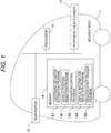
- Fig. 1 is a block diagram showing a configuration of a movable body 1 in a first embodiment of the present invention.
- the movable body 1 includes a control system including a peripheral object sensor 11, a rear display 12, a processor 13, and a memory 14 for holding a plurality of programs.
- the movable body 1 has an autonomous traveling function and includes components necessary for autonomous traveling.
- the peripheral object sensor 11 refers to sensors for recognizing objects around the movable body 1, such as an in-vehicle camera, a radar and a rider (light detection and ranging or laser imaging detection and ranging), and the like and includes any single body of these sensors or a sensor group including a plurality of sensors.
- the rear display 12 is a display device for displaying information such as characters or images with respect to a vehicle traveling at the back of the movable body 1.
- the rear display 12 can change information to be displayed according to an instruction from a program in the connected memory.
- the rear display 12 may have a function of changing a direction and an angle of the display by a physical mechanism (for example, a drive device such as a motor not shown in the drawings), according to an instruction from a program in the connected memory.
- the rear display 12 may have a function of changing setting relating to visibility such as a brightness, according to an instruction from a program in the connected memory.
- An overtaking situation estimation program 141 is a program for causing the processor 13 to execute a process of estimating safety when a following movable body overtakes the movable body 1, on the basis of information of peripheral objects recognized by the peripheral object sensor 11.
- a vehicle position selection program 142 is a program for causing the processor 13 to execute a process of determining a traveling position of the movable body 1 in a lane, on the basis of an overtaking situation estimated by the overtaking situation estimation program 141.
- An operation control program 143 is a program for causing the processor 13 to execute vehicle control for changing the traveling position of the movable body 1 to the traveling position in the lane determined by the vehicle position selection program 142.
- a display information selection program 144 is a program for causing the processor 13 to execute a process of determining information to be displayed on the rear display 12 and rendering the information on the rear display 12, on the basis of an overtaking situation estimated by the overtaking situation estimation program 141. Further, in the case where the rear display 12 has a function of changing settings relating to a direction, an angle, and visibility, the display information selection program 144 may cause the processor 13 to execute a process of changing the setting, according to external information such as a position of the following movable body recognized by the peripheral object sensor 11.
- a process start trigger program 145 is a program for causing the processor 13 to execute a process of monitoring a distance between the following movable body and the movable body 1 recognized by the peripheral object sensor 11 and determining whether the distance becomes a predetermined threshold value or less.
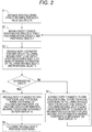
- Fig. 2 is a flowchart showing a whole process of the movable body 1 in the first embodiment of the present invention. Hereinafter, an operation of the present embodiment will be described according to the present flowchart.
- the process start trigger program always uses the peripheral object sensor 11 to detect existence of the following movable body traveling in the same direction as itself (that is, the movable body 1 on which the processor 13 executing the program is mounted) and measure a distance between the movable body and itself.
- the distance with the following movable body becomes the predetermined threshold value x[m] or less, the subsequent process is started (S1).
- the overtaking situation estimation program 141 uses the peripheral object sensor 11 to sense information such as positions of itself, the following movable body where the distance with itself becomes the threshold value x[m] or less, and the peripheral object and traveling speeds of both the movable bodies (S2).
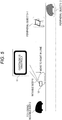
- Fig. 3 is a schematic diagram showing an example of a situation where the movable body 1 performs an overtaking situation estimation in the first embodiment of the present invention.
- the overtaking situation estimation program 141 estimates whether or not the following movable body 2 can safely overtake itself (for example, whether or not the safety of overtaking is higher than a predetermined standard), on the basis of the information sensed in S2 (S3).
- An estimation mechanism uses a method examined for an autonomously traveling movable body, such as a method described in JP 2016-11030 A , for example.
- Known technologies including the method described in the above document are generally mechanisms for verifying the safety when an autonomously traveling movable body overtakes a preceding movable body.
- Fig. 4 is an explanatory diagram showing an example of a situation where it is determined that the following movable body 2 cannot safely overtake the movable body 1 in the first embodiment of the present invention.
- the overtaking situation estimation program 141 determines that the following movable body 2 cannot safely overtake the movable body 1.
- Fig. 5 is an explanatory diagram showing an example of an operation performed by the movable body 1 when it is determined that the following movable body 2 cannot safely overtake the movable body 1 in the first embodiment of the present invention.
- the vehicle position selection program 142 selects a position where the following movable body 2 is hard to overtake the movable body 1 as its own position in the lane.
- the vehicle position selection program 142 may specify a position relation between the movable body 1 and the following movable body 2 on the basis of the information acquired from the peripheral object sensor 11 and may select a position where the following movable body 2 is hard to overtake the movable body 1 and a driver of the following movable body 2 easily views the rear display 12 as its own position in the lane, on the basis of the specified position relation.
- the vehicle position selection program 142 may specify a direction of a screen of the rear display 12 which the driver of the following movable body 2 easily views, on the basis of the specified position relation, and may control a drive device of the rear display 12 so as to be oriented in the direction.
- the vehicle position selection program 142 may select a position closer to the opposite lane than the center of the lane.
- the position closer to the opposite lane than the center of the lane means a rightward position in the lane.
- the rightward position in the lane means the position closer to the opposite lane than the center of the lane and a leftward position in the lane means a position farther from the opposite lane than the center of the lane.
- the leftward position in the lane becomes the position closer to the opposite lane than the center of the lane and the rightward position in the lane becomes the position farther from the opposite lane than the center of the lane.
- the operation control program 143 performs control for moving the movable body 1 to the position in the lane. Specifically, the processor 13 outputs a signal for controlling a steering device (not shown in the drawings) and a drive device (not shown in the drawings) of the movable body 1 and performs control so that the movable body 1 travels at the rightward position in the lane according to the control signal. Further, the display information selection program 144 displays information showing that overtaking is impossible as an estimation result of the safety of overtaking on the rear display 12 (S4). Fig. 5 shows an example of the operation in S4.
- Fig. 7 is an explanatory diagram showing another example of information output by the movable body 1 when it is determined that the following movable body 2 cannot safely overtake the movable body 1 in the first embodiment of the present invention.
- the information displayed by the rear display 12 of the movable body 1 may be, for example, characters such as "overtaking is impossible” shown in Fig. 5 or an image of an icon showing "overtaking is impossible” as shown in Fig. 7A .
- the rear display 12 may display front video photographed by the in-vehicle camera as shown in Fig. 7B .
- the rear display 12 may display a combination thereof.
- the rear display 12 in the above example is an example of a device for outputting an estimation result of the safety of overtaking and notifying the following movable body 2 of information is not limited to being performed by displaying information on the rear display 12.
- the movable body 1 includes an audio output device such as a speaker instead of the rear display 12, audio information may be used to transmit information showing that the overtaking is dangerous to the following movable body 2.
- the video information and the audio information may be combined and output.
- the overtaking situation estimation program 141 returns to S2 after S4 and repeatedly performs the estimation until overtaking can be performed safely.
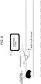
- Fig. 6 is an explanatory diagram showing an example of a situation where it is determined that the following movable body 2 can safely overtake the movable body 1 and an operation performed by the movable body 1 in this situation, in the first embodiment of the present invention.
- the overtaking situation estimation program 141 estimates that overtaking can be performed safely.
- the vehicle position selection program 142 selects a position where the following movable body 2 easily overtakes the movable body 1, such as the left side in the lane, as its own position in the lane.
- the operation control program 143 performs control for moving the movable body 1 to the position in the lane.
- the display information selection program 144 displays information showing that overtaking is safe as an estimation result of the safety of overtaking on the rear display 12 (S5).
- Fig. 6 shows an example of the operation in S5.
- Fig. 8 is an explanatory diagram showing another example of information output by the movable body 1 when it is determined that the following movable body 2 can safely overtake the movable body 1 in the first embodiment of the present invention.
- the information displayed by the rear display 12 of the movable body 1 may be, for example, characters such as "overtaking is safe” shown in Fig. 6 or an image of an icon showing "overtaking is safe” as shown in Fig. 8A .
- the rear display 12 may display front video photographed by the in-vehicle camera as shown in Fig. 8B .
- the rear display 12 may display a combination thereof.
- audio information may be used to transmit information showing that the overtaking can be safely performed to the following movable body 2.
- the processor 13 may control the rear display 12 so that the rear display 12 is easily viewed by the following movable body 1, on the basis of the information acquired from the peripheral object sensor 11. For example, the processor 13 may control the direction of the screen of the rear display 12, as described above.
- the peripheral object sensor 11 includes a further sensor for detecting the surrounding brightness of the movable body 1
- the brightness of the screen of the rear display 12 may be controlled so as to be matched with the surrounding brightness, according to the brightness.
- the driver of the following movable body 2 obtains information showing that overtaking is safe from the movable body 1, the driver can perform overtaking of the movable body 1 by controlling the following movable body 2 (S6).
- the autonomous traveling function may be a complete autonomous traveling function that does not require any operation by a person or may be an autonomous traveling function that requires a partial operation by the person (or can be operated by the person as necessary).
- the control system of the movable body 1 estimates the safety of overtaking of the movable body 1 by the following movable body 2, on the basis of the information acquired from the peripheral object sensor 11, and outputs a result thereof to the following movable body 2. As a result, dangerous overtaking by the following movable body is prevented.
- the control system may control movement of the movable body 1 so that overtaking becomes difficult. Specifically, the control system may control the movable body 1 so that the movable body 1 travels at a position closer to the opposite lane than the center of the lane. As a result, dangerous overtaking by the following movable body 2 is prevented.
- the control system may control movement of the movable body 1 so that overtaking becomes easy. Specifically, the control system may control the movable body 1 so that the movable body 1 travels at a position farther from the opposite lane than the center of the lane and decelerates. As a result, the safety of overtaking by the following movable body 2 is increased and dangerous overtaking is prevented.
- the control system may display the character or the image showing the estimation result of the safety of overtaking with respect to the following movable body 2 or may output the audio information showing the estimation result of the safety of overtaking with respect to the following movable body 2.
- the control system may control the movement of the movable body 1 so that the driver of the following movable body 2 easily views the display and may control the display device to display the character or the image.
- the control system may control the direction of the screen of the display device so that the driver of the following movable body 2 easily views the display or may control the brightness of the screen of the display device to be matched with the surrounding brightness of the movable body 1.
- the driver of the following movable body 2 surely views the display, so that dangerous overtaking is prevented.
- the peripheral object sensor 11 may include a camera for photographing the front of the movable body 1 and the display device may output video photographed by the camera.
- a movable body 1 has an autonomous traveling function.
- the scope of application of the present invention also includes the case where the movable body 1 is operated by a driver who gets on the movable body 1.
- a second embodiment shows a situation where the movable body 1 is operated by the driver who gets on the movable body 1. Since each component of a system according to the second embodiment has the same function as that of each component denoted by the same reference numeral in the first embodiment, except for a difference to be described below, description thereof will be omitted.
- Fig. 9 is a block diagram showing a configuration of the movable body 1 in the second embodiment of the present invention.
- a vehicle position selection program 142 and an operation control program 143 are unnecessary.
- an in-vehicle user interface (UI) 15 to transmit information to the driver of the movable body 1 is necessary.
- the in-vehicle UI 15 includes at least an output device that outputs information to the driver of the movable body 1, for example, a display device that outputs characters or images or a speaker that outputs audio.
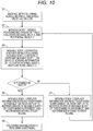
- Fig. 10 is a flowchart showing a whole process of the movable body 1 in the second embodiment of the present invention.
- an operation of the present embodiment will be described according to the present flowchart with a focus on the difference with the first embodiment.
- S1 to S3 The operation of S1 to S3 is the same as that in the first embodiment.
- a display information selection program 144 displays information showing that safe overtaking cannot be performed on a rear display 12, similarly to S4 of the first embodiment. Further, the display information selection program 144 displays information for explaining the corresponding situation to the driver of the movable body 1 and transmitting a recommendation operation on the in-vehicle UI 15 (S7).
- the display information selection program 144 displays information showing that safe overtaking can be performed on the rear display 12, similarly to S5 of the first embodiment. Further, the overtaking situation estimation program 141 displays information for explaining the corresponding situation to the driver of the movable body 1 and transmitting a recommendation operation on the in-vehicle UI 15 (S8).
- the driver of the following movable body 2 that has acquired the information displayed on the rear display 12 in S8 can perform overtaking of the movable body 1 by controlling the following movable body 2 (S9).
- Fig. 11 is an explanatory diagram showing an example of the information displayed on the in-vehicle UI 15 by the movable body 1 in the second embodiment of the present invention.
- Fig. 11A shows an example of information (S7) displayed on the in-vehicle UI 15 in a situation where it is estimated that safe overtaking cannot be performed.
- the in-vehicle UI 15 outputs information recommending traveling at a rightward position in the lane.
- character information showing "Overtaking is dangerous. Please move to the right” is displayed.
- the driver of the movable body 1 controls the movable body 1 so that the movable body 1 travels on the right side in the lane, thereby suppressing overtaking of the movable body 1 by the following movable body 2.
- Fig. 11B shows an example of information (S8) displayed on the in-vehicle UI 15 in a situation where it is estimated that safe overtaking can be performed.
- the in-vehicle UI 15 outputs information recommending traveling at a leftward position in the lane and further deceleration.
- character information showing "Overtaking is preferable. Please decelerate to the left” is displayed.
- the driver of the movable body 1 controls the movable body 1 so that the movable body 1 travels on the left side in the lane and decelerates, thereby inducing overtaking of the movable body 1 by the following movable body 2.
- the in-vehicle UI 15 displays the character information.
- the in-vehicle UI may output information other than the character.
- the in-vehicle UI may display an image showing the recommended control content of the movable body 1 as described above or may output audio for reading the character information.
- the control system of the movable body 1 when it is estimated that overtaking of the movable body 1 by the following movable body 2 cannot be safely performed, the control system of the movable body 1 outputs information recommending traveling at a position closer to the opposite lane than the center of the lane to the driver of the movable body 1.
- the control system of the movable body 1 when it is estimated that overtaking the movable body 1 by the following movable body 2 can be safely performed, the control system of the movable body 1 outputs information recommending traveling at a position farther from the opposite lane than the center of the lane and deceleration to the driver of the movable body 1.
- the driver of the movable body 1 performs an operation according to this information, so that dangerous overtaking by the following movable body 2 is prevented.
- the present invention is not limited to the embodiments described above and various modifications are included.
- the embodiments are described in detail to facilitate the understanding of the present invention and the present invention is not limited to including all of the configurations described above.
- a part of the configurations of the certain embodiment can be replaced by the configurations of another embodiment or the configurations of another embodiment can be added to the configurations of the certain embodiment.
- a part of the configurations of the individual embodiments may be removed or may be added or replaced with other configurations.
- the individual configurations, functions, processing units, and processing mechanisms may be designed by integrated circuits and may be realized by hardware.
- the individual configurations and functions may be realized by software by analyzing programs for realizing the functions by a processor and executing the programs by the processor.
- Information such as programs, tables, and files for realizing the individual functions can be stored in a storage device such as a nonvolatile semiconductor memory, a hard disk drive, and a solid state drive (SSD) and a computer readable non-transitory data storage medium such as an IC card, an SD card, and a DVD.
- SSD solid state drive
- control lines or information lines necessary for explanation are shown and the control lines or information lines do not mean all control lines or information lines necessary for a product. In actuality, almost all configurations may be mutually connected.
Landscapes
- Physics & Mathematics (AREA)
- General Physics & Mathematics (AREA)
- Chemical & Material Sciences (AREA)
- Analytical Chemistry (AREA)
- Life Sciences & Earth Sciences (AREA)
- Atmospheric Sciences (AREA)
- Business, Economics & Management (AREA)
- Emergency Management (AREA)
- Engineering & Computer Science (AREA)
- Multimedia (AREA)
- Traffic Control Systems (AREA)
- Feedback Control In General (AREA)
- Manipulator (AREA)
Applications Claiming Priority (1)
| Application Number | Priority Date | Filing Date | Title |
|---|---|---|---|
| JP2018030184A JP6978962B2 (ja) | 2018-02-22 | 2018-02-22 | 移動体の制御システムおよび制御方法 |
Publications (2)
| Publication Number | Publication Date |
|---|---|
| EP3531394A2 true EP3531394A2 (de) | 2019-08-28 |
| EP3531394A3 EP3531394A3 (de) | 2019-11-20 |
Family
ID=65493887
Family Applications (1)
| Application Number | Title | Priority Date | Filing Date |
|---|---|---|---|
| EP19157702.2A Ceased EP3531394A3 (de) | 2018-02-22 | 2019-02-18 | System und verfahren zur steuerung eines beweglichen körpers |
Country Status (3)
| Country | Link |
|---|---|
| US (1) | US10726728B2 (de) |
| EP (1) | EP3531394A3 (de) |
| JP (1) | JP6978962B2 (de) |
Families Citing this family (3)
| Publication number | Priority date | Publication date | Assignee | Title |
|---|---|---|---|---|
| SE542680C2 (en) * | 2018-07-10 | 2020-06-23 | Scania Cv Ab | A method for controlling a vehicle lighting device, a control device, a vehicle lighting device, a vehicle, a computer program and a computer-readable medium |
| JP2020009289A (ja) * | 2018-07-11 | 2020-01-16 | クラリオン株式会社 | 車両用案内表示装置 |
| JP7838706B2 (ja) * | 2023-03-16 | 2026-04-01 | 日本電気株式会社 | 情報処理装置、情報処理方法及びプログラム |
Citations (8)
| Publication number | Priority date | Publication date | Assignee | Title |
|---|---|---|---|---|
| JP2002319091A (ja) * | 2001-04-20 | 2002-10-31 | Fuji Heavy Ind Ltd | 後続車両認識装置 |
| JP2006293615A (ja) | 2005-04-08 | 2006-10-26 | Denso Corp | 車両の追い越し支援装置 |
| JP2010287162A (ja) | 2009-06-15 | 2010-12-24 | Aisin Aw Co Ltd | 運転支援装置及びプログラム |
| JP2016011030A (ja) | 2014-06-27 | 2016-01-21 | 富士重工業株式会社 | 車両の運転支援装置 |
| CN106125731A (zh) * | 2016-07-21 | 2016-11-16 | 上海海事大学 | 一种基于后方车辆行驶意图识别的无人驾驶车辆运动控制系统及方法 |
| FR3046771A1 (fr) * | 2016-01-18 | 2017-07-21 | Peugeot Citroen Automobiles Sa | Procede et dispositif d’aide a la conduite de vehicule(s) non prioritaire(s) en presence d’un vehicule prioritaire |
| WO2017148531A1 (en) * | 2016-03-04 | 2017-09-08 | Telefonaktiebolaget Lm Ericsson (Publ) | Method and traffic control entity for controlling vehicle traffic |
| US20170301234A1 (en) * | 2016-04-18 | 2017-10-19 | Mando Corporation | System for supporting emergency vehicle using drone |
Family Cites Families (10)
| Publication number | Priority date | Publication date | Assignee | Title |
|---|---|---|---|---|
| GB9111129D0 (en) | 1991-05-23 | 1991-07-17 | Imatronic Ltd | Vehicle collision avoidance |
| US7979173B2 (en) | 1997-10-22 | 2011-07-12 | Intelligent Technologies International, Inc. | Autonomous vehicle travel control systems and methods |
| GB2436916B (en) * | 2006-03-29 | 2008-09-24 | John Turnbull | Warning System |
| JP4953845B2 (ja) * | 2007-02-05 | 2012-06-13 | Udトラックス株式会社 | 安全走行支援装置 |
| WO2016014966A2 (en) * | 2014-07-24 | 2016-01-28 | Brubaker Curtis M | Systems, methods, and devices for generating critical mass in a mobile advertising, media, and communications platform |
| CN107531244B (zh) | 2015-04-21 | 2020-04-21 | 松下知识产权经营株式会社 | 信息处理系统、信息处理方法、以及记录介质 |
| JP6176460B2 (ja) * | 2015-04-24 | 2017-08-09 | マツダ株式会社 | 車両の制御装置 |
| JP6132168B2 (ja) * | 2015-04-24 | 2017-05-24 | マツダ株式会社 | 車両の制御装置 |
| US20170337816A1 (en) * | 2016-05-19 | 2017-11-23 | Toyota Jidosha Kabushiki Kaisha | Wireless Vehicle Data-Enhanced Micro-Navigation Lane Suggestion |
| US20170355306A1 (en) * | 2016-06-08 | 2017-12-14 | Leo Burnett Company, Inc. | Vehicle-Mounted External Display System |
-
2018
- 2018-02-22 JP JP2018030184A patent/JP6978962B2/ja not_active Expired - Fee Related
-
2019
- 2019-02-07 US US16/270,182 patent/US10726728B2/en not_active Expired - Fee Related
- 2019-02-18 EP EP19157702.2A patent/EP3531394A3/de not_active Ceased
Patent Citations (8)
| Publication number | Priority date | Publication date | Assignee | Title |
|---|---|---|---|---|
| JP2002319091A (ja) * | 2001-04-20 | 2002-10-31 | Fuji Heavy Ind Ltd | 後続車両認識装置 |
| JP2006293615A (ja) | 2005-04-08 | 2006-10-26 | Denso Corp | 車両の追い越し支援装置 |
| JP2010287162A (ja) | 2009-06-15 | 2010-12-24 | Aisin Aw Co Ltd | 運転支援装置及びプログラム |
| JP2016011030A (ja) | 2014-06-27 | 2016-01-21 | 富士重工業株式会社 | 車両の運転支援装置 |
| FR3046771A1 (fr) * | 2016-01-18 | 2017-07-21 | Peugeot Citroen Automobiles Sa | Procede et dispositif d’aide a la conduite de vehicule(s) non prioritaire(s) en presence d’un vehicule prioritaire |
| WO2017148531A1 (en) * | 2016-03-04 | 2017-09-08 | Telefonaktiebolaget Lm Ericsson (Publ) | Method and traffic control entity for controlling vehicle traffic |
| US20170301234A1 (en) * | 2016-04-18 | 2017-10-19 | Mando Corporation | System for supporting emergency vehicle using drone |
| CN106125731A (zh) * | 2016-07-21 | 2016-11-16 | 上海海事大学 | 一种基于后方车辆行驶意图识别的无人驾驶车辆运动控制系统及方法 |
Also Published As
| Publication number | Publication date |
|---|---|
| JP6978962B2 (ja) | 2021-12-08 |
| JP2019144971A (ja) | 2019-08-29 |
| US20190259285A1 (en) | 2019-08-22 |
| US10726728B2 (en) | 2020-07-28 |
| EP3531394A3 (de) | 2019-11-20 |
Similar Documents
| Publication | Publication Date | Title |
|---|---|---|
| US10895875B2 (en) | Autonomous driving system | |
| KR102506871B1 (ko) | 자율 주행 제어 장치 및 그의 전방차량 출발 알림 방법 | |
| JP6614777B2 (ja) | 予測的レーン変更支援のための方法及びシステム、プログラムソフトウェア製品、並びに乗り物 | |
| US20220076577A1 (en) | Drive assist device | |
| KR102610748B1 (ko) | 차량의 군집 주행을 위한 사용자 인터페이스 제공 장치 및 방법 | |
| EP3521124A1 (de) | Fahrzeugmontierte vorrichtung, steuerungsverfahren und programm | |
| JP4893507B2 (ja) | 脇見検出装置および方法、並びに、プログラム | |
| US11807277B2 (en) | Driving assistance apparatus | |
| CN114103981B (zh) | 车载显示装置、车载显示方法以及计算机可读存储介质 | |
| US11292398B2 (en) | Apparatus for displaying forward blind spot situation | |
| US12252135B2 (en) | Vehicle controller and method thereof | |
| US10726728B2 (en) | System and method for controlling movable body | |
| JP7670197B2 (ja) | 表示制御装置、表示装置、表示制御方法及びプログラム | |
| CN111196279B (zh) | 用于控制车辆驾驶辅助的装置及方法、包括该装置的系统 | |
| US10272922B2 (en) | Driving support device and driving support method | |
| JP6676789B2 (ja) | 車両におけるアダプティブクルーズコントロールのための追い越し加速支援 | |
| KR20210129800A (ko) | 전방 사각지대 상황 디스플레이 장치 | |
| JP2016224553A (ja) | 車両用交通情報表示システム | |
| KR20240177615A (ko) | 자율 주행 제어 장치 및 그 운전자 상태 판단 방법 | |
| JP2026031611A (ja) | 車両用情報出力制御装置、車両用情報出力制御方法及び車両用情報出力制御プログラム | |
| US11370436B2 (en) | Vehicle controller, system including the same, and method thereof | |
| KR20210129801A (ko) | 전방 사각지대 상황 디스플레이 장치 | |
| US20250256720A1 (en) | Driving assistance device and driving assistance method | |
| US20260097653A1 (en) | Sight-line guidance apparatus, sight-line guidance method, and recording medium | |
| US9428221B2 (en) | Drive assist control device |
Legal Events
| Date | Code | Title | Description |
|---|---|---|---|
| PUAI | Public reference made under article 153(3) epc to a published international application that has entered the european phase |
Free format text: ORIGINAL CODE: 0009012 |
|
| STAA | Information on the status of an ep patent application or granted ep patent |
Free format text: STATUS: REQUEST FOR EXAMINATION WAS MADE |
|
| 17P | Request for examination filed |
Effective date: 20190311 |
|
| AK | Designated contracting states |
Kind code of ref document: A2 Designated state(s): AL AT BE BG CH CY CZ DE DK EE ES FI FR GB GR HR HU IE IS IT LI LT LU LV MC MK MT NL NO PL PT RO RS SE SI SK SM TR |
|
| AX | Request for extension of the european patent |
Extension state: BA ME |
|
| PUAL | Search report despatched |
Free format text: ORIGINAL CODE: 0009013 |
|
| AK | Designated contracting states |
Kind code of ref document: A3 Designated state(s): AL AT BE BG CH CY CZ DE DK EE ES FI FR GB GR HR HU IE IS IT LI LT LU LV MC MK MT NL NO PL PT RO RS SE SI SK SM TR |
|
| AX | Request for extension of the european patent |
Extension state: BA ME |
|
| RIC1 | Information provided on ipc code assigned before grant |
Ipc: G08G 1/16 20060101ALI20191014BHEP Ipc: G08G 1/0967 20060101AFI20191014BHEP |
|
| STAA | Information on the status of an ep patent application or granted ep patent |
Free format text: STATUS: EXAMINATION IS IN PROGRESS |
|
| 17Q | First examination report despatched |
Effective date: 20210909 |
|
| STAA | Information on the status of an ep patent application or granted ep patent |
Free format text: STATUS: THE APPLICATION HAS BEEN REFUSED |
|
| 18R | Application refused |
Effective date: 20240407 |