EP3532258B1 - Procédé de fabrication d'un produit en bois stratifié - Google Patents
Procédé de fabrication d'un produit en bois stratifié Download PDFInfo
- Publication number
- EP3532258B1 EP3532258B1 EP17864276.5A EP17864276A EP3532258B1 EP 3532258 B1 EP3532258 B1 EP 3532258B1 EP 17864276 A EP17864276 A EP 17864276A EP 3532258 B1 EP3532258 B1 EP 3532258B1
- Authority
- EP
- European Patent Office
- Prior art keywords
- plank
- less
- weight
- crack
- wedging
- Prior art date
- Legal status (The legal status is an assumption and is not a legal conclusion. Google has not performed a legal analysis and makes no representation as to the accuracy of the status listed.)
- Active
Links
Images

Classifications
-
- B—PERFORMING OPERATIONS; TRANSPORTING
- B27—WORKING OR PRESERVING WOOD OR SIMILAR MATERIAL; NAILING OR STAPLING MACHINES IN GENERAL
- B27M—WORKING OF WOOD NOT PROVIDED FOR IN SUBCLASSES B27B - B27L; MANUFACTURE OF SPECIFIC WOODEN ARTICLES
- B27M1/00—Working of wood not provided for in subclasses B27B - B27L, e.g. by stretching
- B27M1/003—Mechanical surface treatment
-
- B—PERFORMING OPERATIONS; TRANSPORTING
- B27—WORKING OR PRESERVING WOOD OR SIMILAR MATERIAL; NAILING OR STAPLING MACHINES IN GENERAL
- B27D—WORKING VENEER OR PLYWOOD
- B27D1/00—Joining wood veneer with any material; Forming articles thereby; Preparatory processing of surfaces to be joined, e.g. scoring
- B27D1/005—Tenderising, e.g. by incising, crushing
-
- B—PERFORMING OPERATIONS; TRANSPORTING
- B27—WORKING OR PRESERVING WOOD OR SIMILAR MATERIAL; NAILING OR STAPLING MACHINES IN GENERAL
- B27D—WORKING VENEER OR PLYWOOD
- B27D1/00—Joining wood veneer with any material; Forming articles thereby; Preparatory processing of surfaces to be joined, e.g. scoring
- B27D1/04—Joining wood veneer with any material; Forming articles thereby; Preparatory processing of surfaces to be joined, e.g. scoring to produce plywood or articles made therefrom; Plywood sheets
- B27D1/08—Manufacture of shaped articles; Presses specially designed therefor
-
- B—PERFORMING OPERATIONS; TRANSPORTING
- B27—WORKING OR PRESERVING WOOD OR SIMILAR MATERIAL; NAILING OR STAPLING MACHINES IN GENERAL
- B27F—DOVETAILED WORK; TENONS; SLOTTING MACHINES FOR WOOD OR SIMILAR MATERIAL; NAILING OR STAPLING MACHINES
- B27F1/00—Dovetailed work; Tenons; Making tongues or grooves; Groove- and- tongue jointed work; Finger- joints
- B27F1/02—Making tongues or grooves, of indefinite length
-
- B—PERFORMING OPERATIONS; TRANSPORTING
- B27—WORKING OR PRESERVING WOOD OR SIMILAR MATERIAL; NAILING OR STAPLING MACHINES IN GENERAL
- B27M—WORKING OF WOOD NOT PROVIDED FOR IN SUBCLASSES B27B - B27L; MANUFACTURE OF SPECIFIC WOODEN ARTICLES
- B27M1/00—Working of wood not provided for in subclasses B27B - B27L, e.g. by stretching
- B27M1/02—Working of wood not provided for in subclasses B27B - B27L, e.g. by stretching by compressing
-
- B—PERFORMING OPERATIONS; TRANSPORTING
- B27—WORKING OR PRESERVING WOOD OR SIMILAR MATERIAL; NAILING OR STAPLING MACHINES IN GENERAL
- B27M—WORKING OF WOOD NOT PROVIDED FOR IN SUBCLASSES B27B - B27L; MANUFACTURE OF SPECIFIC WOODEN ARTICLES
- B27M1/00—Working of wood not provided for in subclasses B27B - B27L, e.g. by stretching
- B27M1/08—Working of wood not provided for in subclasses B27B - B27L, e.g. by stretching by multi-step processes
-
- B—PERFORMING OPERATIONS; TRANSPORTING
- B27—WORKING OR PRESERVING WOOD OR SIMILAR MATERIAL; NAILING OR STAPLING MACHINES IN GENERAL
- B27M—WORKING OF WOOD NOT PROVIDED FOR IN SUBCLASSES B27B - B27L; MANUFACTURE OF SPECIFIC WOODEN ARTICLES
- B27M3/00—Manufacture or reconditioning of specific semi-finished or finished articles
- B27M3/0013—Manufacture or reconditioning of specific semi-finished or finished articles of composite or compound articles
- B27M3/0026—Manufacture or reconditioning of specific semi-finished or finished articles of composite or compound articles characterised by oblong elements connected laterally
- B27M3/0053—Manufacture or reconditioning of specific semi-finished or finished articles of composite or compound articles characterised by oblong elements connected laterally using glue
-
- B—PERFORMING OPERATIONS; TRANSPORTING
- B27—WORKING OR PRESERVING WOOD OR SIMILAR MATERIAL; NAILING OR STAPLING MACHINES IN GENERAL
- B27M—WORKING OF WOOD NOT PROVIDED FOR IN SUBCLASSES B27B - B27L; MANUFACTURE OF SPECIFIC WOODEN ARTICLES
- B27M3/00—Manufacture or reconditioning of specific semi-finished or finished articles
- B27M3/0013—Manufacture or reconditioning of specific semi-finished or finished articles of composite or compound articles
- B27M3/0086—Manufacture or reconditioning of specific semi-finished or finished articles of composite or compound articles characterised by connecting using glue
-
- B—PERFORMING OPERATIONS; TRANSPORTING
- B32—LAYERED PRODUCTS
- B32B—LAYERED PRODUCTS, i.e. PRODUCTS BUILT-UP OF STRATA OF FLAT OR NON-FLAT, e.g. CELLULAR OR HONEYCOMB, FORM
- B32B21/00—Layered products comprising a layer of wood, e.g. wood board, veneer, wood particle board
- B32B21/02—Layered products comprising a layer of wood, e.g. wood board, veneer, wood particle board the layer being formed of fibres, chips, or particles, e.g. MDF, HDF, OSB, chipboard, particle board, hardboard
-
- B—PERFORMING OPERATIONS; TRANSPORTING
- B32—LAYERED PRODUCTS
- B32B—LAYERED PRODUCTS, i.e. PRODUCTS BUILT-UP OF STRATA OF FLAT OR NON-FLAT, e.g. CELLULAR OR HONEYCOMB, FORM
- B32B21/00—Layered products comprising a layer of wood, e.g. wood board, veneer, wood particle board
- B32B21/04—Layered products comprising a layer of wood, e.g. wood board, veneer, wood particle board comprising wood as the main or only constituent of a layer, which is next to another layer of the same or of a different material
- B32B21/042—Layered products comprising a layer of wood, e.g. wood board, veneer, wood particle board comprising wood as the main or only constituent of a layer, which is next to another layer of the same or of a different material of wood
-
- B—PERFORMING OPERATIONS; TRANSPORTING
- B32—LAYERED PRODUCTS
- B32B—LAYERED PRODUCTS, i.e. PRODUCTS BUILT-UP OF STRATA OF FLAT OR NON-FLAT, e.g. CELLULAR OR HONEYCOMB, FORM
- B32B21/00—Layered products comprising a layer of wood, e.g. wood board, veneer, wood particle board
- B32B21/04—Layered products comprising a layer of wood, e.g. wood board, veneer, wood particle board comprising wood as the main or only constituent of a layer, which is next to another layer of the same or of a different material
- B32B21/08—Layered products comprising a layer of wood, e.g. wood board, veneer, wood particle board comprising wood as the main or only constituent of a layer, which is next to another layer of the same or of a different material of synthetic resin
-
- B—PERFORMING OPERATIONS; TRANSPORTING
- B32—LAYERED PRODUCTS
- B32B—LAYERED PRODUCTS, i.e. PRODUCTS BUILT-UP OF STRATA OF FLAT OR NON-FLAT, e.g. CELLULAR OR HONEYCOMB, FORM
- B32B21/00—Layered products comprising a layer of wood, e.g. wood board, veneer, wood particle board
- B32B21/10—Next to a fibrous or filamentary layer
-
- B—PERFORMING OPERATIONS; TRANSPORTING
- B32—LAYERED PRODUCTS
- B32B—LAYERED PRODUCTS, i.e. PRODUCTS BUILT-UP OF STRATA OF FLAT OR NON-FLAT, e.g. CELLULAR OR HONEYCOMB, FORM
- B32B21/00—Layered products comprising a layer of wood, e.g. wood board, veneer, wood particle board
- B32B21/13—Layered products comprising a layer of wood, e.g. wood board, veneer, wood particle board all layers being exclusively wood
-
- B—PERFORMING OPERATIONS; TRANSPORTING
- B32—LAYERED PRODUCTS
- B32B—LAYERED PRODUCTS, i.e. PRODUCTS BUILT-UP OF STRATA OF FLAT OR NON-FLAT, e.g. CELLULAR OR HONEYCOMB, FORM
- B32B21/00—Layered products comprising a layer of wood, e.g. wood board, veneer, wood particle board
- B32B21/14—Layered products comprising a layer of wood, e.g. wood board, veneer, wood particle board comprising wood board or veneer
-
- B—PERFORMING OPERATIONS; TRANSPORTING
- B32—LAYERED PRODUCTS
- B32B—LAYERED PRODUCTS, i.e. PRODUCTS BUILT-UP OF STRATA OF FLAT OR NON-FLAT, e.g. CELLULAR OR HONEYCOMB, FORM
- B32B3/00—Layered products comprising a layer with external or internal discontinuities or unevennesses, or a layer of non-planar shape; Layered products comprising a layer having particular features of form
- B32B3/10—Layered products comprising a layer with external or internal discontinuities or unevennesses, or a layer of non-planar shape; Layered products comprising a layer having particular features of form characterised by a discontinuous layer, i.e. formed of separate pieces of material
- B32B3/18—Layered products comprising a layer with external or internal discontinuities or unevennesses, or a layer of non-planar shape; Layered products comprising a layer having particular features of form characterised by a discontinuous layer, i.e. formed of separate pieces of material characterised by an internal layer formed of separate pieces of material which are juxtaposed side-by-side
-
- B—PERFORMING OPERATIONS; TRANSPORTING
- B32—LAYERED PRODUCTS
- B32B—LAYERED PRODUCTS, i.e. PRODUCTS BUILT-UP OF STRATA OF FLAT OR NON-FLAT, e.g. CELLULAR OR HONEYCOMB, FORM
- B32B5/00—Layered products characterised by the non- homogeneity or physical structure, i.e. comprising a fibrous, filamentary, particulate or foam layer; Layered products characterised by having a layer differing constitutionally or physically in different parts
- B32B5/02—Layered products characterised by the non- homogeneity or physical structure, i.e. comprising a fibrous, filamentary, particulate or foam layer; Layered products characterised by having a layer differing constitutionally or physically in different parts characterised by structural features of a fibrous or filamentary layer
- B32B5/022—Non-woven fabric
-
- B—PERFORMING OPERATIONS; TRANSPORTING
- B32—LAYERED PRODUCTS
- B32B—LAYERED PRODUCTS, i.e. PRODUCTS BUILT-UP OF STRATA OF FLAT OR NON-FLAT, e.g. CELLULAR OR HONEYCOMB, FORM
- B32B5/00—Layered products characterised by the non- homogeneity or physical structure, i.e. comprising a fibrous, filamentary, particulate or foam layer; Layered products characterised by having a layer differing constitutionally or physically in different parts
- B32B5/02—Layered products characterised by the non- homogeneity or physical structure, i.e. comprising a fibrous, filamentary, particulate or foam layer; Layered products characterised by having a layer differing constitutionally or physically in different parts characterised by structural features of a fibrous or filamentary layer
- B32B5/024—Woven fabric
-
- B—PERFORMING OPERATIONS; TRANSPORTING
- B32—LAYERED PRODUCTS
- B32B—LAYERED PRODUCTS, i.e. PRODUCTS BUILT-UP OF STRATA OF FLAT OR NON-FLAT, e.g. CELLULAR OR HONEYCOMB, FORM
- B32B5/00—Layered products characterised by the non- homogeneity or physical structure, i.e. comprising a fibrous, filamentary, particulate or foam layer; Layered products characterised by having a layer differing constitutionally or physically in different parts
- B32B5/02—Layered products characterised by the non- homogeneity or physical structure, i.e. comprising a fibrous, filamentary, particulate or foam layer; Layered products characterised by having a layer differing constitutionally or physically in different parts characterised by structural features of a fibrous or filamentary layer
- B32B5/12—Layered products characterised by the non- homogeneity or physical structure, i.e. comprising a fibrous, filamentary, particulate or foam layer; Layered products characterised by having a layer differing constitutionally or physically in different parts characterised by structural features of a fibrous or filamentary layer characterised by the relative arrangement of fibres or filaments of different layers, e.g. the fibres or filaments being parallel or perpendicular to each other
-
- B—PERFORMING OPERATIONS; TRANSPORTING
- B32—LAYERED PRODUCTS
- B32B—LAYERED PRODUCTS, i.e. PRODUCTS BUILT-UP OF STRATA OF FLAT OR NON-FLAT, e.g. CELLULAR OR HONEYCOMB, FORM
- B32B7/00—Layered products characterised by the relation between layers; Layered products characterised by the relative orientation of features between layers, or by the relative values of a measurable parameter between layers, i.e. products comprising layers having different physical, chemical or physicochemical properties; Layered products characterised by the interconnection of layers
- B32B7/04—Interconnection of layers
- B32B7/12—Interconnection of layers using interposed adhesives or interposed materials with bonding properties
-
- E—FIXED CONSTRUCTIONS
- E04—BUILDING
- E04C—STRUCTURAL ELEMENTS; BUILDING MATERIALS
- E04C2/00—Building elements of relatively thin form for the construction of parts of buildings, e.g. sheet materials, slabs, or panels
- E04C2/02—Building elements of relatively thin form for the construction of parts of buildings, e.g. sheet materials, slabs, or panels characterised by specified materials
- E04C2/10—Building elements of relatively thin form for the construction of parts of buildings, e.g. sheet materials, slabs, or panels characterised by specified materials of wood, fibres, chips, vegetable stems, or the like; of plastics; of foamed products
- E04C2/12—Building elements of relatively thin form for the construction of parts of buildings, e.g. sheet materials, slabs, or panels characterised by specified materials of wood, fibres, chips, vegetable stems, or the like; of plastics; of foamed products of solid wood
-
- E—FIXED CONSTRUCTIONS
- E04—BUILDING
- E04C—STRUCTURAL ELEMENTS; BUILDING MATERIALS
- E04C3/00—Structural elongated elements designed for load-supporting
- E04C3/02—Joists; Girders, trusses, or trusslike structures, e.g. prefabricated; Lintels; Transoms; Braces
- E04C3/12—Joists; Girders, trusses, or trusslike structures, e.g. prefabricated; Lintels; Transoms; Braces of wood, e.g. with reinforcements, with tensioning members
- E04C3/122—Laminated
-
- B—PERFORMING OPERATIONS; TRANSPORTING
- B27—WORKING OR PRESERVING WOOD OR SIMILAR MATERIAL; NAILING OR STAPLING MACHINES IN GENERAL
- B27B—SAWS FOR WOOD OR SIMILAR MATERIAL; COMPONENTS OR ACCESSORIES THEREFOR
- B27B5/00—Sawing machines working with circular or cylindrical saw blades; Components or equipment therefor
- B27B5/02—Sawing machines working with circular or cylindrical saw blades; Components or equipment therefor characterised by a special purpose only
- B27B5/06—Sawing machines working with circular or cylindrical saw blades; Components or equipment therefor characterised by a special purpose only for dividing plates in parts of determined size, e.g. panels
- B27B5/065—Sawing machines working with circular or cylindrical saw blades; Components or equipment therefor characterised by a special purpose only for dividing plates in parts of determined size, e.g. panels with feedable saw blades, e.g. arranged on a carriage
- B27B5/075—Sawing machines working with circular or cylindrical saw blades; Components or equipment therefor characterised by a special purpose only for dividing plates in parts of determined size, e.g. panels with feedable saw blades, e.g. arranged on a carriage characterised by having a plurality of saw blades, e.g. turning about perpendicular axes
-
- B—PERFORMING OPERATIONS; TRANSPORTING
- B27—WORKING OR PRESERVING WOOD OR SIMILAR MATERIAL; NAILING OR STAPLING MACHINES IN GENERAL
- B27F—DOVETAILED WORK; TENONS; SLOTTING MACHINES FOR WOOD OR SIMILAR MATERIAL; NAILING OR STAPLING MACHINES
- B27F1/00—Dovetailed work; Tenons; Making tongues or grooves; Groove- and- tongue jointed work; Finger- joints
- B27F1/02—Making tongues or grooves, of indefinite length
- B27F1/04—Making tongues or grooves, of indefinite length along only one edge of a board
-
- B—PERFORMING OPERATIONS; TRANSPORTING
- B32—LAYERED PRODUCTS
- B32B—LAYERED PRODUCTS, i.e. PRODUCTS BUILT-UP OF STRATA OF FLAT OR NON-FLAT, e.g. CELLULAR OR HONEYCOMB, FORM
- B32B2250/00—Layers arrangement
- B32B2250/03—3 layers
-
- B—PERFORMING OPERATIONS; TRANSPORTING
- B32—LAYERED PRODUCTS
- B32B—LAYERED PRODUCTS, i.e. PRODUCTS BUILT-UP OF STRATA OF FLAT OR NON-FLAT, e.g. CELLULAR OR HONEYCOMB, FORM
- B32B2250/00—Layers arrangement
- B32B2250/40—Symmetrical or sandwich layers, e.g. ABA, ABCBA, ABCCBA
-
- B—PERFORMING OPERATIONS; TRANSPORTING
- B32—LAYERED PRODUCTS
- B32B—LAYERED PRODUCTS, i.e. PRODUCTS BUILT-UP OF STRATA OF FLAT OR NON-FLAT, e.g. CELLULAR OR HONEYCOMB, FORM
- B32B2307/00—Properties of the layers or laminate
- B32B2307/50—Properties of the layers or laminate having particular mechanical properties
- B32B2307/546—Flexural strength; Flexion stiffness
-
- B—PERFORMING OPERATIONS; TRANSPORTING
- B32—LAYERED PRODUCTS
- B32B—LAYERED PRODUCTS, i.e. PRODUCTS BUILT-UP OF STRATA OF FLAT OR NON-FLAT, e.g. CELLULAR OR HONEYCOMB, FORM
- B32B2307/00—Properties of the layers or laminate
- B32B2307/70—Other properties
- B32B2307/732—Dimensional properties
Definitions
- the present disclosure relates to a method of making a laminated wood product, according to the preamble of claim 1. Such a method is known from the document EP 2535155 A1 .
- the method is specifically suitable for processing of so-called hardwood, but may also be used for softwood.
- beech is attractive, because of its strength properties, which are actually superior to those of spruce.
- Beech exhibits more shrinkage than e.g. spruce and is thus more prone to deforming (twisting, bowing, cupping, crooking) in connection with drying than spruce.
- dried planks of beech call for more removal of material in order to achieve planar planks, than corresponding planks of spruce.
- processing of beech is associated with greater material losses than processing of spruce.
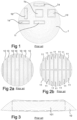
- Fig.1 illustrates how different plank or rod geometries 1a, 1b, 1c, 1d, 1e, 1f may be cut from a piece of raw material in the form of a wooden log 1.
- the orientation of the year rings will differ between different parts of the cross section.
- planks or rods cut from different parts of the log will deform differently as they dry, as indicated in Fig. 1 .
- Figs 2a-2b schematically illustrate how a log 1 is typically cut into a plurality of planks.
- the log 1 may be cut along a plurality of parallel longitudinal planes, such that a plurality of wood planks 10 are formed.
- the log 1 may be cut into planks 11 along one or more first longitudinal planes, and then subsequently along one or more second longitudinal planes perpendicular to the first longitudinal planes.
- one first longitudinal cutting plane is provided, whereby the log is cut in halves having a respective semicircular cross section, and subsequently eight second longitudinal cutting planes, which are all perpendicular to the first one, and typically equally spaced from each other.
- each plank will have its unique properties and thus its unique deformation when drying.
- Fig. 3 schematically illustrates a cross section of a cupped plank 10. Such cupping typically occurs during the drying process. From Fig. 3 , it can be deduced how much material would need to be cut away in order to provide a plank 101 having a rectangular cross section. In reality, losses of about 40-50 % are not uncommon.
- An objective of the present disclosure is to provide a method which reduces the loss of material and thus provides for more efficient use of beech, and other hard and soft woods as a construction material.
- a method of producing a laminated wood product comprising providing a plank presenting a pair of parallel major surfaces, a pair of minor surfaces, a pair of end surfaces and a longitudinal direction parallel with said major and minor surfaces and perpendicular to the end surfaces, said plank having a water content of more than 25 % by weight, preferably more than 30 % by weight.
- Initializing according to the invention at least one longitudinal crack in the plank, drying said crack initialized plank to a moisture content of less than 20 % by weight, and laminating said crack initialized plank by gluing at least one of its major surfaces to a surface of a second member, thus forming the laminated wood product.
- a method of controlling the initiation of cracks in a plank is provided, both with regards to the location of a crack as well as to the number of cracks to be created.
- the term “longitudinal” is understood to refer to a direction which is substantially parallel with a main fiber direction of such log or plank.
- the term “substantial” here reflects that fibers are not always perfectly straight throughout the log or plank, and that there may be local variations in fiber direction, e.g. due to knots or other defects.
- width is understood to refer to a direction that is perpendicular to the longitudinal direction, parallel with a major cut surface of the plank.
- the term “thickness” is understood to refer to a direction which is perpendicular to the major cut surface of the plank.
- a "plank” is a typically elongate piece of sawn lumber, which is formed of one piece of lumber and which is integral. That is, all pieces making up a plank remain connected, albeit with cracks and partial separations, and thus have not been artificially joined together.
- An initialized crack means that the plank has been provided with a notch or dent from which a crack may start propagating.
- the second member may be one or more planks, a wood fiber based board, a chipboard, a film, a web, etc.
- the invention is based on the insight that, in many circumstances, longitudinal cracks are more of an optical, or aesthetic, problem, than a strength problem.
- the strength properties may nevertheless be equal, or close to equal, to a laminated structure lamellae that are non-cracked. Hence, the cracks do not prevent the fiber strength from being utilized.
- the overall yield may be increased.
- cracked planks may allow for faster drying.
- the initializing comprises according to the invention wedging into the plank.
- the wedging may be performed towards at least one of the end surfaces.
- the wedging may comprise applying a force by a wedge member in a direction +/- 45°, preferably +/- 30°, +/- 10° or approximately perpendicular, to a surface normal of the end surfaces.
- the wedging may be performed with a wedge edge, which is oriented substantially perpendicular to the major surfaces.
- the wedging may be performed with a wedge edge, which is oriented substantially perpendicular to a year ring tangent where the wedge engages the end surface.
- the wedge edge may be driven into the end surface less than 5 % of a plank length, preferably less than 1 % or less than 0.1 % of the plank length.
- the wedges may be driven only a few centimeters, or even millimeters, into the end surface.
- the initializing may comprise providing a longitudinal notch in at least one of the major surfaces.
- the longitudinal notch may comprise wedging or cutting into the major surface.
- the longitudinal notch may comprise sawing or milling into the major surface.
- the notch may be continuous over at least 50 % of a length of the plank, preferably over at least 70 % or at least 90 %.
- the notch may be discontinuous and presents at least two aligned notch sections of less than 45 % of a length of the plank, preferably less than 30 % or less than 10 %.
- the notch sections may be aligned longitudinally along the plank, or along a feature of the plank, such as a year ring or a fiber.
- a notch depth may be less than 90 % of a plank thickness, preferably less than 30 %, less than 20 % or less than 10 %.
- notch depth may be on the order of 0.5-5 mm.
- the method may further comprise measuring a wedging force, whereby the wedging may be performed until the wedging force starts decreasing.
- the initializing may comprise cutting into the plank.
- the cutting may comprise removing material in the form of dust or chips.
- the cutting may be performed towards an end surface of the plank.
- the cutting may be performed towards a major surface of the plank.
- At least two laterally spaced cracks may be initiated along respective longitudinal directions of one major surface.
- the cracks may be spaced apart by a distance corresponding to a thickness of the plank +/- 25 %, preferably +/-10 %.
- the method may further comprise obtaining data on fiber directions of at least part of the at least one of the major surfaces and initiating at least one crack parallel with such fiber direction.
- the method may further comprise opening at least one initiated crack.
- Such opening may comprise applying a torque about an axis parallel with the longitudinal direction of the plank.
- the plank may, prior to said drying, have a water content of less than 40 % by weight, preferably less than 35 % by weight.
- the laminating may be performed before the drying step.
- the second member may present a water content of less than 25 % by weight, preferably less than 20 % by weight.
- the second member may present a water content of more than 25 % by weight, preferably more than 30 % by weight.
- the method may further comprise a sanding step and/or a planing step of at least one of the major surfaces after the drying and prior to the laminating.
- the laminating may be performed after the drying step.
- the second member may present a water content of less than 25 % by weight, preferably less than 20 % by weight.
- the plank may be formed of hardwood, i.e. from an angiosperm tree species, having a dry wood density of more than 400 kg/m 3 .
- “Dry wood” is defined as wood having a moisture content that is typical to commercial lumber, i.e. wood which has been air-dried or kiln-dried. Usually this moisture content may be on the order of 8-18 % by weight.
- a laminated wood product comprising a first layer which is formed of at least one hardwood plank presenting a pair of parallel major surfaces, a pair of minor surfaces, a pair of end surfaces and a longitudinal direction parallel with said major and minor surfaces and perpendicular to the end surfaces, said plank having a water content of less than 25 % by weight, and said plank presents a pair of juxtaposed plank portions, at least partially separated by an open gap running along a fiber direction of the plank, said gap presenting crack surfaces; and at least one second layer, laminated to the major surface.
- a crack surface is a surface of a crack or split of the wood, and may be recognized in that it is generally irregular and generally follows the fiber direction of the wood without cutting off the fibers. Cracks and splits are characterized in that originally adjacent wood fibers have been separated in a direction perpendicular to their longitudinal directions without removal of material.
- an "open gap” herein refers to that the crack surfaces are physically separated by said gap, i.e. at the position of a gap the respective crack surfaces are not connected to each other for example by means of any filling material or substance.
- the crack may present a depth from at least one major surface of 5 - 100% of a thickness of the plank, preferably of 5-90 % of a more preferably 10-50 %.
- the laminated wood product may further comprise at least two second layers, which sandwich said plank.
- the two second sandwiching layers may be non-cracked.
- the at least two second layers may present fiber directions which are substantially perpendicular to the fiber direction of the plank.
- a plank forming part of the second layer may extend across the gap. That is, a plank forming part of the second layer may be offset in its width direction relative to the plank of the first layer.
- At least two second layers may present fiber directions which are substantially parallel to the fiber direction of the plank.
- said gap running along a fiber direction of the plank is an open crack, meaning that a non-filled gap is created between the two inner longitudinal side surfaces of a crack.
- non-filled is to be interpreted as “empty” or "void of any filling material or substance”.
- An embodiment wherein the cracks are unfilled leads to the advantage that any natural dimensional changes of the wood e.g. in the form of shrinking and swelling caused by changes in humidity are tolerated thus avoiding undesired tension in the plank and/or the upcome of uncontrolled cracks.
- any swelling or shrinking will mainly occur inside the plank and build-up of tensions in the material is minimized.
- the fact that the cracks are open leads to that water vapor may be ventilated through the air inside the cracks to/from the wood tissue upon humidity changes,.
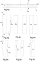
- Fig 4a-4d and 5a-5b show a strategy to increase the overall yield: If you would leave the boards intact ( Fig. 4b ) there will be no two identical boards, so it will be very difficult to fit them together into a layer with small gaps. Normally you would trim the edges to get boards with parallel edges. On the other hand most boards can be split symmetrically in the middle, so that the two halves can be fit together nicely, as illustrated, which results in a layer where you have rather small gaps between the boards and small trimming waste.
- Figs 4a-4d schematically illustrate how an approximately trapezoidal plank 20 may be cut longitudinally and rearranged in order to provide an approximately rectangular aggregate panel.
- the plank 20 may be cut along a longitudinal line, thereby forming a pair of plank pieces 21a, 21b.
- the plank pieces 21a, 21b By shifting positions of the plank pieces 21a, 21b such that their rounded edges face each other and also turning one of the plank pieces 21b about 180° about an axis that is parallel with the plank's 21b width direction W (and thus perpendicular to its length direction), the plank pieces may be arranged with their respective longitudinal cut edges parallel and with a minimum gap between the plank pieces 21a, 21b.
- the rounded edges 22a, 22b may wholly or partially overlap each other.
- Figs. 5a-5c schematically illustrate how a bent plank 30 may be cut and rearranged to provide an approximately rectangular aggregate panel.
- plank 30 may be cut along a longitudinal line to form a pair of plank pieces 31a, 31b of which one has a convex longitudinal edge 32a and the other one has a concave longitudinal edge 32b.
- the plank pieces 31a, 31b By shifting positions of the plank pieces 31a, 31b such that their rounded edges face each other and also turning one of the plank pieces 31b about 180° about an axis that is parallel with the plank's 31b width direction W (and thus perpendicular to its length direction), the plank pieces may be arranged with their respective longitudinal cut edges parallel and with a minimum gap between the plank pieces 31a, 31b. Moreover, the rounded edges 32a, 32b may wholly or partially overlap each other.
- the principles of Figs 4a-4d and 5a-5c can be used in order to optimize use of planks when forming, in particular, cross laminated timber products.
- a plank typically presents a pair of substantially planar, mutually parallel major surfaces, a pair of minor surfaces and a pair of end surfaces.
- a longitudinal direction L is defined as the direction between the end surfaces.
- the major surfaces extend substantially parallel with the longitudinal direction, as do the minor surfaces.
- the plank has a thickness direction T, perpendicular to the major surfaces and a width W, perpendicular to both the major surfaces and to the thickness.
- Plank length (L direction) may be on the order of 200-10000 mm, most often about 1000-5000 mm.
- Plank thickness (T direction) may be on the order of 5-50 mm, most often about 10-40 mm.
- Plank width (W direction) may be on the order of 30-1000 mm, most often about 50-500 mm.
- plank's major surfaces may be rectangular or trapezoidal in shape.
- the minor surfaces may, but need not be mutually parallel.
- a principal fiber direction of the plank may extend substantially parallel with the longitudinal direction, i.e. parallel +/- 20°, preferably +/- 10° or +/- 5°.
- the end surfaces may be substantially perpendicular to at least one of the major and minor surfaces.
- a longitudinal crack may be defined as a crack that extends along the longitudinal direction of the plank. Preferably, such a crack will propagate along a fiber direction of the plank, along the length direction and/or along the thickness direction.
- the crack initialized, or cracked, plank may be laminated to at least one second layer when wet, as defined above, or after a drying step.
- the plank members, to whom the plank is laminated may be dry or wet.
- the laminated product may then be subject to drying.
- the crack initialized, or cracked, plank may be dried prior to lamination.
- the plank may need formatting, such as sanding and/or planing in order to restore a sufficiently planar shape to allow for lamination.
- a cracked or crack-initiated plank is much more flexible than a non-cracked plank.
- the cracked plank can be pressed flat and the planing losses can thus be made much smaller compared to a conventional plank.
- a planing step may be combined with a pressing step, wherein the plank is pressed, e.g. by a calendar arrangement, in the thickness direction while being planed.
- a first set of calendar rolls may be arranged immediately upstream of the planing tool and a second set of calendar rolls may be arranged downstream of the planing tool.
- Drying may also be performed in the conventional manner, such as kiln drying.
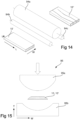
- the thus crack initiated, or cracked, plank 10' may be included, alone, or arranged coplanarly with other planks 10', 12, as a layer L1 of a laminated wood product 1000, as shown in Fig. 16 .
- Fig. 16 there is seen an example of a laminated wood product 1000 according to the invention, wherein a middle layer L1 is made up by crack initiated or cracked boards 10', and adjacent, sandwiching outer layers L2, L3 are made from non-cracked planks.
- the planks 10' may optionally have its initiated cracks opened, or completed. However, it is preferred that cracks are only opened or completed to an extent that allows the plank to still form one piece. That is, portions of the plank situated on different sides of a longitudinal crack should remain held together.
- Lamination of the crack initiated or cracked planks 10' may be performed in conventional manner.
- the lamination may take place using adhesive selected for the particular system that is to be laminated.
- adhesive selected for the particular system that is to be laminated.
- a wet gluing system may be used, such as polyurethane based glue.
- the lamination may be supplemented by further measures, such as application of pressure, in particular in a direction perpendicular to a lamination plane (here the major surfaces), to the laminate in connection with the drying, setting or hardening of the adhesive.
- a catalyst or other reaction initiating measures may be supplied, such as radiation (UV light), heat or water (which is used in polyurethane systems).
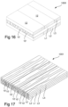
- a plurality of crack initiated or cracked planks 10', 10" may be arranged coplanarly side by side, optionally with a minor gap between adjacent plank edges, whereby major surfaces of the planks 10' are laminated to major surfaces of further layers L2, L3.
- the further layers L2, L3, L4 may comprise further crack initiated or cracked planks 10', 10", which may be arranged with their longitudinal directions parallel to the planks, but shifted laterally (in the width direction W), such that each crack/gap is bridged by the further plank. This is illustrated by the product 1001 in Fig. 17 .
- the further layers L2, L3 may comprise further crack initiated or cracked planks 10', 10", which may be arranged with their longitudinal directions at an angle other than parallel, such as perpendicular, to the planks, such that a cross laminated wood product is provided. This is illustrated in Fig. 16 .
- one or more of the further layer(s) L2, L3 may comprise or consist of planks 12 that are neither (deliberately) cracked nor crack initiated, as illustrated in Fig. 16 .
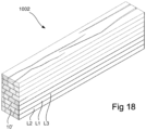
- cracked or crack initiated planks 10', 10" may be laminated major surface to major surface to provide a beam 1002, as illustrated in Fig. 18 .
- some planks may be cracked or crack initiated and others may not be.
- outermost planks, as seen in the thickness direction T may, for aesthetic reasons, be non-cracked.
- the further layers with which the cracked or crack initiated planks are laminated may comprise, or consist of, other cracked or crack initiated planks, normal planks or board materials, such as fiber board, chip board, MDF, HDF or even polymer films, woven or non-woven webs or plastic sheets.
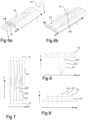
- Figs 6-12b illustrate various ways of artificially initiating a crack in a wood plank.
- Figs 6-9 illustrate various ways of initiating a longitudinal crack by wedging or cutting into a short edge of the plank.
- Fig. 6a there is illustrated a trapezoidal (with respect to major surface shape) plank 10 and a plurality of wedging tools 5, 6.
- three wedging tools 5 may be applied, each having a respective wedge edge 51, which extends perpendicular to the major surfaces of the plank, and which is driven into at least one end surface of the plank, substantially along the longitudinal direction.
- the wedge edge 51 may be oriented at an angle, as seen in a plane perpendicular to the major surface and to the short edges (i.e. a L-T plane) other than perpendicular to the end surface. It is also understood that the wedge may be driven in a direction which is not perpendicular to the end surface. Moreover, the wedge edge may be linear in shape, or it may be pointed, convex, concave, etc.
- An extent of this wedging may be on the order of one or a few millimeters, up to one or a few (typically less than 5) centimeters, as the purpose may be to only initiate a crack, but not to complete it such that the pieces on opposite sides of the crack would separate.
- more than one crack may be initiated, such that multiple longitudinal cracks are provided.
- Cracks may typically be initiated with a spacing, as seen in a direction W transversely of the longitudinal direction L, of 50-200 % of a thickness T of the plank, preferably about 50-150 %, 75-150 % or 100-150 % of such thickness T.
- cracks C1, C2, C3 may, but need not, be initiated from both ends of a plank 10.
- three cracks are initiated by first wedging tools 5 from the major end surface and two cracks are initiated by second wedging tools 6 from the minor end surface.
- the number of cracks initiated at a minor end surface may be on the order of n-a, where n is the number of cracks initiated at the major end surface and a is an integer value of 0-3.
- Fig. 7 there is illustrated a case where the number of a is 0, that is, the number of cracks C1, C2, C3 initiated at each short edge are the same. Other than that, the device illustrated in Fig. 7 operates in the same manner as that of Fig. 6a .
- FIG. 6b there is illustrated another way of initiating cracks.
- cracks are initiated on the major surfaces using a device, wherein one or more wedging tools 6' are caused to perform an oscillating motion in a direction perpendicular to the major surfaces. That is, the wedging tools 6' will reciprocate towards and away from the major surface, forming, at each cycle, a longitudinally extending elongate dent in the major surface.
- the wedging tools 6' may have their wedge edges 62 parallel with the longitudinal direction L, and optionally also with the major surface towards which it is to act.
- Longitudinal spacing of such dents may be varied by varying the oscillation frequency and/or the speed with which the plank is being fed past the wedging tool. Hence, it is possible to provide everything from a continuous groove along the length of the plank to one or a few separate dents along the length of each plank.
- the wedging tools may be rotatable about an axis perpendicular to the major surface, such that the orientation of the wedge edge 62 may be tuned to follow fiber direction in the major surface.
- the rotation may be limited to +/- 20°, +/- 10° or +/- 5°, relative to the longitudinal axis L.
- Such wedging tools may be provided to operate on one or both major surfaces of the plank.
- Fig. 8 illustrates a first principle of orienting the wedge edges in Figs 6 or 7 .
- the wedge edges are aligned with year ring radii of the plank, or actually of the log from which the plank was formed. For example, it is possible to achieve this by analyzing curvature of year rings of the plank, derive a tangent of each year ring at each lateral position where a crack is to be initiated, and to align the wedge edge 51, 61 such that it is perpendicular to the tangent of the year ring at that position.
- Fig. 9 illustrates the principle used in Figs 6a and 7 . That is, the wedge edges 51, 61 are simply arranged perpendicular to the major surface.
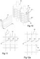
- Figs 10-12b illustrate various ways of initiating a longitudinal crack by wedging or cutting into a major surface of the plank.
- Fig. 10 there is illustrated a first way of wedging into a major surface of the plank,.
- At least one calendar 9a, 9b having a cutting edge 911, 921 extending along a portion of its circumference it is possible cause at least one calendar 9a, 9b having a cutting edge 911, 921 extending along a portion of its circumference to interact with a major surface of the plank while the plank and the calendar 9a, 9b move relative each other.
- the calendar 9a, 9b is stationary and rotatable, whereby the plank is passed by it while being pressed against the calendar.
- the plank may be propelled by the calendars 9a, 9b, and both surfaces may be crack-initiated at the same time.
- each calendar 9a, 9b may comprise at least one circumferential cutting edge 911, 921. However, it may be rational to provide more such circumferential cutting edges 911, 921.
- a first set 91 of partially circumferential cutting edges 911 may be axially aligned and spaced from each other.
- An axial spacing between adjacent cutting edges 911 may be on the order of the crack spacing mentioned above, as seen in a direction W transversely of the longitudinal direction L. That is 50-200 % of a thickness T of the plank, preferably about 50-150 %, 75-150 % or 100-150 % of such thickness T.
- One or more further sets 92 of partially circumferential cutting edges 921 may be axially aligned and spaced from each other, and optionally axially offset from the first set 91. Preferably, this further set may also be angularly offset from the first set.
- each partially circumferential cutting edge 911, 921 may extend over a portion of the circumference corresponding to about 10°-45° angle about a central axis of the calendar. That is, a length of the cutting edge 911, 921 may correspond to about 10°-45° of the central angle.
- a circumferential offset between two adjacent sets 91, 92 of cutting edges 911, 921 may be on the order of 50-150 % of the cutting edge length.
- One or both calendars 9a, 9b may be provided with cutting edges 911, 921.
- both calendars 9a, 9b have cutting edges 911, 921, as illustrated in Fig. 10 .
- only one of the calendars have cutting edges, while the other one merely provides support and assists in driving the plank, and pressing it towards the calendar having cutting edges.
- FIG. 11 there is illustrated another way of initiating cracks C1, C2, C3.
- each crack initiating tool 7 is formed by a rotatable cutting disk, having a continuous (possibly non-serrated) cutting edge 71, which, depending on its sharpness and the force applied, wedges into and/or cuts into at least one of the major surfaces of the plank 10.
- a respective set of tools is operable on each major surface of the plank 10.
- This cutting edge 71 may be caused to move relative to the plank in a substantially slip-free manner, i.e. there is no relative movement between the cutting disk edge 71 and the plank 10.
- the cutting disks 7 may be controllably movable in the transverse direction, such that the groove or cut formed by each grooving tool may follow fibers of the wood.
- the cutting disks 7 may be individually rotatable, each independently with regard to other disks on the same axle 72 or major surface, or rotatable as a group on a common axle.
- a plurality of rotatable saw blades 8 are provided, each of which presenting a saw edge 81 for cutting a shallow groove in the major surface of the plank. Thus, material is being removed from these grooves.
- the saw blades 8 may be controllably movable in the transverse direction, such that the groove formed by each saw blade 7 may follow fibers of the wood.
- the saw blades 8 may be individually rotatable, each independently with regard to other disks on the same axle or major surface, or rotatable as a group on a common axle 82.
- the cutting depth may be relatively shallow, preferably on the order of 5-35 %, preferably 5-25 %, of the thickness of the plank. This way, the amount of material removed is reduced.
- cutting depth of the saw blades 8 may be as much as 50-90 % of the thickness of the plank 10, possibly 70-90 % or 80-90 %.
- the cuts C1', C2' may extend over more than half of the plank thickness, which will further facilitate any subsequent cracking process.
- a first device for opening, or completing, cracks comprises at least two pairs 93a, 93b, 93c of rollers 93a1, 93a2; 93b1, 93b2; 93c1, 93c2, wherein the rollers 93a1, 93a2 of a first pair 93a are rotatable about first mutually parallel axes 93a3, 93a4 and wherein the rollers 93b1, 93b2 of the second pair are rotatable about second mutually parallel axes.
- the first and second parallel axes 93b3, 93b4 present an angle of 5°-45°, preferably 10°-30°.
- the pairs 93a, 93b, 93c of rollers simultaneously engage laterally (in the W direction) juxtaposed portions of the plank 10, 10', typically (but not necessarily) a crack-initiated plank 10', such that a bending torque is applied to the plank about an axis parallel with the longitudinal direction L of the plank.
- the plank 10' is fed along its longitudinal direction L through the roller pairs 93a, 93b, 93c, and is thus successively bent and thus cracked.
- the plank may optionally be passed through at least two successive set of rollers, wherein the angle between the axes of the roller sets gradually increase.
- a second device for opening cracks comprises at least three rollers 94a, 94b, 94c, one of which 94a arranged to engage a first major surface of the plank and the others 94b, 94c arranged to simultaneously engage the second major surface of the plank, which may be pristine or crack-initiated.
- the rollers 94a, 94b, 94c are arranged such that a line that tangents both second rollers 94b, 94c at points facing the first roller 94a presents a minimum distance to the periphery of the first roller 94a, which minimum distance is less than a thickness of the plank that is to be processed, preferably less than 75 % of said thickness or less than 50 % of said thickness.
- the distance may be zero or negative. That is, the periphery of the first roller may tangent or intersect said line.
- the plank 10, 10' may be passed through the rollers along its transversal direction.
- the rollers may be of length equal to the plank.
- plank 10 When the plank 10" has been passed through the device of Fig. 13 , it will typically be cracked. However, as mentioned, it is desirable only to crack the plank to such an extent that it still forms an integral piece of material. In the alternative, two or more sets of spaced apart rollers may be provided.
- a third device 95 for opening cracks comprises a pair of profiled members 95a, 95b, one 95b of which being concave and the other one 95a being convex.
- the profiled members 95a, 95b may be provided as a pressing tool, wherein one or more planks 10, 10' are cracked in each cycle.
- the profiled members 95a, 95b may be formed as rollers, whereby the plank 10, 10' may be passed between the rollers in a manner similar to that illustrated in Fig. 13 .
Landscapes
- Engineering & Computer Science (AREA)
- Life Sciences & Earth Sciences (AREA)
- Wood Science & Technology (AREA)
- Forests & Forestry (AREA)
- Mechanical Engineering (AREA)
- Architecture (AREA)
- Manufacturing & Machinery (AREA)
- Civil Engineering (AREA)
- Structural Engineering (AREA)
- Textile Engineering (AREA)
- Laminated Bodies (AREA)
- Veneer Processing And Manufacture Of Plywood (AREA)
Claims (25)
- Procédé de production d'un produit en bois laminé (1000, 1001, 1002), comprenant :
la fourniture d'une planche (10) présentant une paire de surfaces majeures (10a, 10b) parallèles, une paire de surfaces mineures (10c, 10d), une paire de surfaces d'extrémité (10e, 10f) et une direction longitudinale (L) parallèle auxdites surfaces majeures et mineures (10a, 10b ; 10c, 10d) et perpendiculaire aux surfaces d'extrémité (10e, 10f), ladite planche ayant une teneur en eau de plus de 25 % en poids, de préférence de plus de 30 % en poids, caractérisé en ce qu'il comprend :l'amorce de l'au moins une fissure longitudinale dans la planche (10) par calage dans la planche, laquelle planche a une teneur en eau de plus de 25 % en poids,le séchage de ladite planche (10') à fissure amorcée jusqu'à une teneur en humidité inférieure à 20 % en poids, etla stratification de ladite planche (10', 10'') à fissure amorcée par collage de l'au moins une de ses surfaces majeures (10a, 10b) sur une surface d'un deuxième élément, formant ainsi le produit en bois lamellé (1000, 1001, 1002). - Procédé selon la revendication 1, dans lequel le calage est réalisé vers l'au moins une des surfaces d'extrémité (10e, 10f).
- Procédé selon la revendication 2, dans lequel ledit calage est réalisé avec un bord de coin (51, 61) qui est orienté sensiblement perpendiculairement aux surfaces majeures (10a, 10b).
- Procédé selon la revendication 1 ou 2, dans lequel ledit calage est réalisé avec un bord de coin (51, 61) qui est orienté sensiblement perpendiculairement à une tangente de cerne annuel où le coin vient en prise avec la surface d'extrémité (10e, 10f).
- Procédé selon l'une quelconque des revendications précédentes, dans lequel ledit bord de coin (51, 61) est entraîné dans la surface d'extrémité (10e, 10f) à moins de 5 % d'une longueur de planche, de préférence à moins de 1 % ou à moins de 0,1 % de la longueur de planche.
- Procédé selon l'une quelconque des revendications précédentes, dans lequel ladite amorce comprend la fourniture d'une encoche longitudinale dans l'au moins une des surfaces majeures (10a, 10b).
- Procédé selon la revendication 6, dans lequel la réalisation de l'encoche longitudinale comprend le calage ou la découpe dans la surface majeure (10a, 10b).
- Procédé selon la revendication 6, dans lequel la fourniture de l'encoche longitudinale comprend le sciage ou le fraisage dans la surface majeure (10a, 10b).
- Procédé selon l'une quelconque des revendications 6 à 8, dans lequel l'encoche est continue sur au moins 50 % d'une longueur de la planche (10'), de préférence sur au moins 70 % ou au moins 90 %.
- Procédé selon l'une quelconque des revendications 6 à 8, dans lequel l'encoche est discontinue et présente au moins deux sections d'encoche alignées de moins de 45 % d'une longueur de la planche (10'), de préférence moins de 30 % ou moins de 10 %.
- Procédé selon l'une quelconque des revendications 6 à 10, dans lequel une profondeur d'encoche est inférieure à 90 % d'une épaisseur de planche, de préférence inférieure à 30 %, inférieure à 20 % ou inférieure à 10 %.
- Procédé selon l'une quelconque des revendications 1 à 5 ou 7 à 11, comprenant en outre la mesure d'une force de calage, dans lequel ledit calage est réalisé jusqu'à ce que la force de calage commence à diminuer.
- Procédé selon l'une quelconque des revendications précédentes, dans lequel au moins deux fissures espacées latéralement sont amorcées le long de directions respectives sensiblement longitudinales (L) d'une surface majeure (10a, 10b).
- Procédé selon la revendication 14, dans lequel les fissures sont espacées d'une distance correspondant à une épaisseur de la planche +/- 25 %, de préférence +/- 10 %.
- Procédé selon l'une quelconque des revendications précédentes, comprenant en outre l'obtention de données sur les directions de fibre de l'au moins une partie de l'au moins une des surfaces majeures et l'amorce d'au moins une fissure parallèle à une telle direction de fibre.
- Procédé selon l'une quelconque des revendications précédentes, comprenant en outre l'ouverture de l'au moins une fissure amorcée.
- Procédé selon la revendication 16, dans lequel ladite ouverture comprend l'application d'un couple autour d'un axe parallèle à la direction longitudinale de la planche (10, 10').
- Procédé selon l'une quelconque des revendications précédentes, dans lequel la planche, avant ledit séchage, a une teneur en eau inférieure à 40 % en poids, de préférence inférieure à 35 % en poids.
- Procédé selon l'une quelconque des revendications précédentes, dans lequel la lamination est réalisée avant l'étape de séchage.
- Procédé selon l'une quelconque des revendications précédentes, dans lequel le deuxième élément présente une teneur en eau inférieure à 25 % en poids, de préférence inférieure à 20 % en poids.
- Procédé selon l'une quelconque des revendications 1 à 15, dans lequel le deuxième élément présente une teneur en eau de plus de 25 % en poids, de préférence de plus de 30 % en poids.
- Procédé selon l'une quelconque des revendications précédentes, comprenant en outre une étape de ponçage et/ou une étape de rabotage de l'au moins une des surfaces majeures après le séchage et avant la lamination.
- Procédé selon l'une quelconque des revendications 1 à 18, dans lequel la lamination est réalisée après l'étape de séchage.
- Procédé selon la revendication 22, dans lequel le deuxième élément présente une teneur en eau inférieure à 25 % en poids, de préférence inférieure à 20 % en poids.
- Procédé selon l'une quelconque des revendications précédentes, dans lequel la planche est formée de bois dur, c'est-à-dire à partir d'une espèce d'arbre angiosperme, ayant une masse volumique de bois sec supérieure à 400 kg/m3, ou à partir de bois tendre.
Applications Claiming Priority (2)
| Application Number | Priority Date | Filing Date | Title |
|---|---|---|---|
| SE1651424A SE540292C2 (en) | 2016-10-28 | 2016-10-28 | Method of making a laminated wood product and such a laminated wood product |
| PCT/IB2017/056647 WO2018078556A1 (fr) | 2016-10-28 | 2017-10-26 | Procédé de fabrication d'un produit en bois stratifié |
Publications (4)
| Publication Number | Publication Date |
|---|---|
| EP3532258A1 EP3532258A1 (fr) | 2019-09-04 |
| EP3532258A4 EP3532258A4 (fr) | 2020-07-08 |
| EP3532258C0 EP3532258C0 (fr) | 2025-06-11 |
| EP3532258B1 true EP3532258B1 (fr) | 2025-06-11 |
Family
ID=62023292
Family Applications (1)
| Application Number | Title | Priority Date | Filing Date |
|---|---|---|---|
| EP17864276.5A Active EP3532258B1 (fr) | 2016-10-28 | 2017-10-26 | Procédé de fabrication d'un produit en bois stratifié |
Country Status (10)
| Country | Link |
|---|---|
| US (2) | US10843371B2 (fr) |
| EP (1) | EP3532258B1 (fr) |
| CN (1) | CN110087842A (fr) |
| BR (1) | BR112019008460B1 (fr) |
| CA (1) | CA3041768A1 (fr) |
| EA (1) | EA201991057A1 (fr) |
| ES (1) | ES3034432T3 (fr) |
| PL (1) | PL3532258T3 (fr) |
| SE (1) | SE540292C2 (fr) |
| WO (1) | WO2018078556A1 (fr) |
Families Citing this family (5)
| Publication number | Priority date | Publication date | Assignee | Title |
|---|---|---|---|---|
| US12510489B2 (en) * | 2018-09-18 | 2025-12-30 | Solarwood International Pty Ltd | Manufacturing wood products |
| US11084245B2 (en) * | 2019-01-09 | 2021-08-10 | Six Minutes LLC | Cross-laminated timber having a conduit therein |
| FI12763Y1 (fi) * | 2020-07-02 | 2020-09-04 | Honkarakenne Oyj | Lamellihirsi |
| AT524651B1 (de) * | 2021-03-17 | 2022-08-15 | Agentur Riener Gmbh | Gefräste ausziehbare Funktionsplatte |
| DE102023116006B3 (de) * | 2023-06-19 | 2024-05-23 | Minda Industrieanlagen Gmbh | Verfahren zum Herstellen von mit Ausschnitten versehenen Brettsperrholzplatten |
Family Cites Families (15)
| Publication number | Priority date | Publication date | Assignee | Title |
|---|---|---|---|---|
| US357521A (en) | 1887-02-08 | byrkit | ||
| DE553854C (de) | 1930-10-18 | 1932-07-01 | Schmidt Karl | Kernbrett fuer Sperrplatten, dessen Faserzusammenhang teilweise zerstoert ist |
| US3427216A (en) * | 1965-02-24 | 1969-02-11 | Johns Manville | Building material laminate |
| US4473099A (en) * | 1979-08-20 | 1984-09-25 | Masaru Koike | Method and apparatus for drying veneer sheet |
| GB2058315B (en) | 1979-08-20 | 1984-04-04 | Meinan Machinery Works | Method of and apparatus for drying veneer sheet |
| US4747899A (en) * | 1986-01-31 | 1988-05-31 | Meinan Machinery Works, Inc. | Method for improving the mechanical strength of veneer sheets having lathe checks |
| JP3492828B2 (ja) | 1995-09-07 | 2004-02-03 | 株式会社太平製作所 | 単板積層材 |
| AU2001275894A1 (en) | 2000-07-17 | 2002-01-30 | Anderson-Tully Engineered Wood, L.L.C. | Veneer face plywood flooring and methods of making the same |
| AUPR388201A0 (en) | 2001-03-21 | 2001-04-12 | University Of Melbourne, The | Modified wood product and process for the preparation thereof |
| DE102004020063A1 (de) | 2004-04-24 | 2005-11-17 | Man Nutzfahrzeuge Ag | Verfahren zum Bruchtrennen wieder zusammensetzbarer Bauteile oder deren Vormaterialien |
| CN101357470B (zh) * | 2008-06-03 | 2010-09-29 | 中国林业科学研究院木材工业研究所 | 一种重组木及其制造方法 |
| CN101607411B (zh) * | 2009-07-27 | 2012-04-11 | 中国林业科学研究院木材工业研究所 | 竹纤维增强复合材料及其制造方法 |
| AT11958U1 (de) * | 2010-09-07 | 2011-08-15 | Hans-Peter Ing Leitinger | Verfahren zur verarbeitung von roh-rundholz und keilverzinkte holzverbundprodukte |
| AT511209B1 (de) * | 2011-06-15 | 2012-10-15 | Mafi Naturholzboden Gmbh | Verfahren zur beeinflussung des optischen erscheinungsbildes eines holzelementes |
| JP2014113748A (ja) | 2012-12-10 | 2014-06-26 | Uni Wood Corporation Co Ltd | 裏割れを利用する板材並びにその製造方法 |
-
2016
- 2016-10-28 SE SE1651424A patent/SE540292C2/en not_active IP Right Cessation
-
2017
- 2017-10-26 EA EA201991057A patent/EA201991057A1/ru unknown
- 2017-10-26 US US16/345,440 patent/US10843371B2/en active Active
- 2017-10-26 BR BR112019008460-6A patent/BR112019008460B1/pt active IP Right Grant
- 2017-10-26 CA CA3041768A patent/CA3041768A1/fr active Pending
- 2017-10-26 CN CN201780066654.6A patent/CN110087842A/zh active Pending
- 2017-10-26 WO PCT/IB2017/056647 patent/WO2018078556A1/fr not_active Ceased
- 2017-10-26 PL PL17864276.5T patent/PL3532258T3/pl unknown
- 2017-10-26 ES ES17864276T patent/ES3034432T3/es active Active
- 2017-10-26 EP EP17864276.5A patent/EP3532258B1/fr active Active
-
2020
- 2020-10-16 US US17/072,219 patent/US11383403B2/en active Active
Also Published As
| Publication number | Publication date |
|---|---|
| BR112019008460B1 (pt) | 2023-11-28 |
| SE540292C2 (en) | 2018-05-22 |
| EP3532258A1 (fr) | 2019-09-04 |
| EP3532258C0 (fr) | 2025-06-11 |
| EA201991057A1 (ru) | 2019-09-30 |
| ES3034432T3 (en) | 2025-08-18 |
| EP3532258A4 (fr) | 2020-07-08 |
| US20210031402A1 (en) | 2021-02-04 |
| SE1651424A1 (en) | 2018-04-29 |
| US10843371B2 (en) | 2020-11-24 |
| PL3532258T3 (pl) | 2025-09-01 |
| US11383403B2 (en) | 2022-07-12 |
| US20190275698A1 (en) | 2019-09-12 |
| CN110087842A (zh) | 2019-08-02 |
| BR112019008460A2 (pt) | 2019-07-09 |
| CA3041768A1 (fr) | 2018-05-03 |
| WO2018078556A1 (fr) | 2018-05-03 |
Similar Documents
| Publication | Publication Date | Title |
|---|---|---|
| US11383403B2 (en) | Method of making a laminated wood product | |
| US5255726A (en) | Substantially uncurved and unwaved plywood produced by using veneers with unstraight fibers and method for producing such a plywood | |
| US6695944B2 (en) | Veneer face plywood flooring and methods of making the same | |
| US5352317A (en) | Method of preparing a multilayered solid wood panel | |
| EP0196302B1 (fr) | Fabrication de produits de bois reconstitue | |
| CN107735233B (zh) | 生产层叠的木制品的方法,以及层叠的木制品 | |
| US5560409A (en) | Backsawn timber production from radially sawn wedges | |
| EP3352986A1 (fr) | Procédé de formation d'un composant de bois stratifié, et composant de bois stratifié ainsi formé | |
| WO1989004747A1 (fr) | Procede de sciage de bois et produits de bois ainsi realises | |
| JP5367498B2 (ja) | ベニヤレース及び積層板の製造方法 | |
| WO1999044796A1 (fr) | Procede de fabrication d'une plaque en bambou, dispositif de decoupe en continu de plaque de bambou et plaque de bambou ainsi obtenue | |
| US20190240860A1 (en) | Laminated-Veneer-Lumber Product and Method for Producing the Same | |
| US3878017A (en) | Method of making a decorative building panel of lumber planks and laminated veneer plies | |
| KR101779810B1 (ko) | 목질판상재료와 천연목재 가공판재를 사용한 합판 제조방법을 통한 원형봉 가공방법 | |
| JP2013240899A (ja) | 針葉樹原木から旋削されたベニヤ単板の脱水装置 | |
| US20170037205A1 (en) | Unknown | |
| JP2019089215A (ja) | 表面加工用積層材製品とその製造方法 | |
| US20010035071A1 (en) | Dieboard and method of construction | |
| JPH09234711A (ja) | 木質系複合材料の製造方法 | |
| EP3259104A1 (fr) | Bois de placage pliable en trois dimensions | |
| JP2017226142A (ja) | 木材製造方法 |
Legal Events
| Date | Code | Title | Description |
|---|---|---|---|
| STAA | Information on the status of an ep patent application or granted ep patent |
Free format text: STATUS: THE INTERNATIONAL PUBLICATION HAS BEEN MADE |
|
| PUAI | Public reference made under article 153(3) epc to a published international application that has entered the european phase |
Free format text: ORIGINAL CODE: 0009012 |
|
| STAA | Information on the status of an ep patent application or granted ep patent |
Free format text: STATUS: REQUEST FOR EXAMINATION WAS MADE |
|
| 17P | Request for examination filed |
Effective date: 20190528 |
|
| AK | Designated contracting states |
Kind code of ref document: A1 Designated state(s): AL AT BE BG CH CY CZ DE DK EE ES FI FR GB GR HR HU IE IS IT LI LT LU LV MC MK MT NL NO PL PT RO RS SE SI SK SM TR |
|
| AX | Request for extension of the european patent |
Extension state: BA ME |
|
| DAV | Request for validation of the european patent (deleted) | ||
| DAX | Request for extension of the european patent (deleted) | ||
| A4 | Supplementary search report drawn up and despatched |
Effective date: 20200609 |
|
| RIC1 | Information provided on ipc code assigned before grant |
Ipc: B27M 1/08 20060101AFI20200604BHEP Ipc: B27D 1/00 20060101ALI20200604BHEP Ipc: B27M 1/00 20060101ALI20200604BHEP Ipc: B32B 21/13 20060101ALI20200604BHEP Ipc: B32B 21/14 20060101ALI20200604BHEP Ipc: E04C 3/12 20060101ALI20200604BHEP Ipc: B32B 21/04 20060101ALI20200604BHEP Ipc: B27M 3/00 20060101ALI20200604BHEP Ipc: B27B 5/075 20060101ALI20200604BHEP |
|
| STAA | Information on the status of an ep patent application or granted ep patent |
Free format text: STATUS: EXAMINATION IS IN PROGRESS |
|
| 17Q | First examination report despatched |
Effective date: 20220112 |
|
| GRAP | Despatch of communication of intention to grant a patent |
Free format text: ORIGINAL CODE: EPIDOSNIGR1 |
|
| STAA | Information on the status of an ep patent application or granted ep patent |
Free format text: STATUS: GRANT OF PATENT IS INTENDED |
|
| INTG | Intention to grant announced |
Effective date: 20250114 |
|
| GRAS | Grant fee paid |
Free format text: ORIGINAL CODE: EPIDOSNIGR3 |
|
| GRAA | (expected) grant |
Free format text: ORIGINAL CODE: 0009210 |
|
| STAA | Information on the status of an ep patent application or granted ep patent |
Free format text: STATUS: THE PATENT HAS BEEN GRANTED |
|
| AK | Designated contracting states |
Kind code of ref document: B1 Designated state(s): AL AT BE BG CH CY CZ DE DK EE ES FI FR GB GR HR HU IE IS IT LI LT LU LV MC MK MT NL NO PL PT RO RS SE SI SK SM TR |
|
| REG | Reference to a national code |
Ref country code: GB Ref legal event code: FG4D |
|
| REG | Reference to a national code |
Ref country code: CH Ref legal event code: EP |
|
| REG | Reference to a national code |
Ref country code: IE Ref legal event code: FG4D |
|
| REG | Reference to a national code |
Ref country code: DE Ref legal event code: R096 Ref document number: 602017089929 Country of ref document: DE |
|
| U01 | Request for unitary effect filed |
Effective date: 20250709 |
|
| U07 | Unitary effect registered |
Designated state(s): AT BE BG DE DK EE FI FR IT LT LU LV MT NL PT RO SE SI Effective date: 20250715 |
|
| REG | Reference to a national code |
Ref country code: ES Ref legal event code: FG2A Ref document number: 3034432 Country of ref document: ES Kind code of ref document: T3 Effective date: 20250818 |
|
| PG25 | Lapsed in a contracting state [announced via postgrant information from national office to epo] |
Ref country code: GR Free format text: LAPSE BECAUSE OF FAILURE TO SUBMIT A TRANSLATION OF THE DESCRIPTION OR TO PAY THE FEE WITHIN THE PRESCRIBED TIME-LIMIT Effective date: 20250912 |
|
| PGFP | Annual fee paid to national office [announced via postgrant information from national office to epo] |
Ref country code: NO Payment date: 20250925 Year of fee payment: 9 |
|
| PGFP | Annual fee paid to national office [announced via postgrant information from national office to epo] |
Ref country code: GB Payment date: 20250923 Year of fee payment: 9 |
|
| PG25 | Lapsed in a contracting state [announced via postgrant information from national office to epo] |
Ref country code: HR Free format text: LAPSE BECAUSE OF FAILURE TO SUBMIT A TRANSLATION OF THE DESCRIPTION OR TO PAY THE FEE WITHIN THE PRESCRIBED TIME-LIMIT Effective date: 20250611 |
|
| PG25 | Lapsed in a contracting state [announced via postgrant information from national office to epo] |
Ref country code: RS Free format text: LAPSE BECAUSE OF FAILURE TO SUBMIT A TRANSLATION OF THE DESCRIPTION OR TO PAY THE FEE WITHIN THE PRESCRIBED TIME-LIMIT Effective date: 20250911 |
|
| PGFP | Annual fee paid to national office [announced via postgrant information from national office to epo] |
Ref country code: CZ Payment date: 20250929 Year of fee payment: 9 |
|
| REG | Reference to a national code |
Ref country code: CH Ref legal event code: U11 Free format text: ST27 STATUS EVENT CODE: U-0-0-U10-U11 (AS PROVIDED BY THE NATIONAL OFFICE) Effective date: 20251101 |
|
| U20 | Renewal fee for the european patent with unitary effect paid |
Year of fee payment: 9 Effective date: 20251031 |
|
| PG25 | Lapsed in a contracting state [announced via postgrant information from national office to epo] |
Ref country code: IS Free format text: LAPSE BECAUSE OF FAILURE TO SUBMIT A TRANSLATION OF THE DESCRIPTION OR TO PAY THE FEE WITHIN THE PRESCRIBED TIME-LIMIT Effective date: 20251011 |
|
| PG25 | Lapsed in a contracting state [announced via postgrant information from national office to epo] |
Ref country code: SM Free format text: LAPSE BECAUSE OF FAILURE TO SUBMIT A TRANSLATION OF THE DESCRIPTION OR TO PAY THE FEE WITHIN THE PRESCRIBED TIME-LIMIT Effective date: 20250611 |
|
| PGFP | Annual fee paid to national office [announced via postgrant information from national office to epo] |
Ref country code: CH Payment date: 20251101 Year of fee payment: 9 |
|
| PGFP | Annual fee paid to national office [announced via postgrant information from national office to epo] |
Ref country code: PL Payment date: 20251014 Year of fee payment: 9 |
|
| PG25 | Lapsed in a contracting state [announced via postgrant information from national office to epo] |
Ref country code: SK Free format text: LAPSE BECAUSE OF FAILURE TO SUBMIT A TRANSLATION OF THE DESCRIPTION OR TO PAY THE FEE WITHIN THE PRESCRIBED TIME-LIMIT Effective date: 20250611 |
|
| PGFP | Annual fee paid to national office [announced via postgrant information from national office to epo] |
Ref country code: ES Payment date: 20251103 Year of fee payment: 9 |
|
| PLBE | No opposition filed within time limit |
Free format text: ORIGINAL CODE: 0009261 |
|
| STAA | Information on the status of an ep patent application or granted ep patent |
Free format text: STATUS: NO OPPOSITION FILED WITHIN TIME LIMIT |
|
| REG | Reference to a national code |
Ref country code: CH Ref legal event code: L10 Free format text: ST27 STATUS EVENT CODE: U-0-0-L10-L00 (AS PROVIDED BY THE NATIONAL OFFICE) Effective date: 20260423 |