EP3532372B1 - Verschlusslamelle - Google Patents
Verschlusslamelle Download PDFInfo
- Publication number
- EP3532372B1 EP3532372B1 EP17797548.9A EP17797548A EP3532372B1 EP 3532372 B1 EP3532372 B1 EP 3532372B1 EP 17797548 A EP17797548 A EP 17797548A EP 3532372 B1 EP3532372 B1 EP 3532372B1
- Authority
- EP
- European Patent Office
- Prior art keywords
- hollow body
- watercraft
- closure
- outer skin
- figures
- Prior art date
- Legal status (The legal status is an assumption and is not a legal conclusion. Google has not performed a legal analysis and makes no representation as to the accuracy of the status listed.)
- Active
Links
Images





Classifications
-
- B—PERFORMING OPERATIONS; TRANSPORTING
- B63—SHIPS OR OTHER WATERBORNE VESSELS; RELATED EQUIPMENT
- B63G—OFFENSIVE OR DEFENSIVE ARRANGEMENTS ON VESSELS; MINE-LAYING; MINE-SWEEPING; SUBMARINES; AIRCRAFT CARRIERS
- B63G13/00—Other offensive or defensive arrangements on vessels; Vessels characterised thereby
- B63G13/02—Camouflage
-
- B—PERFORMING OPERATIONS; TRANSPORTING
- B63—SHIPS OR OTHER WATERBORNE VESSELS; RELATED EQUIPMENT
- B63B—SHIPS OR OTHER WATERBORNE VESSELS; EQUIPMENT FOR SHIPPING
- B63B19/00—Arrangements or adaptations of ports, doors, windows, port-holes, or other openings or covers
- B63B19/08—Ports or like openings in vessels' sides or at the vessels' bow or stern
-
- E—FIXED CONSTRUCTIONS
- E05—LOCKS; KEYS; WINDOW OR DOOR FITTINGS; SAFES
- E05F—DEVICES FOR MOVING WINGS INTO OPEN OR CLOSED POSITION; CHECKS FOR WINGS; WING FITTINGS NOT OTHERWISE PROVIDED FOR, CONCERNED WITH THE FUNCTIONING OF THE WING
- E05F15/00—Power-operated mechanisms for wings
- E05F15/50—Power-operated mechanisms for wings using fluid-pressure actuators
- E05F15/56—Power-operated mechanisms for wings using fluid-pressure actuators for horizontally-sliding wings
-
- E—FIXED CONSTRUCTIONS
- E05—LOCKS; KEYS; WINDOW OR DOOR FITTINGS; SAFES
- E05F—DEVICES FOR MOVING WINGS INTO OPEN OR CLOSED POSITION; CHECKS FOR WINGS; WING FITTINGS NOT OTHERWISE PROVIDED FOR, CONCERNED WITH THE FUNCTIONING OF THE WING
- E05F15/00—Power-operated mechanisms for wings
- E05F15/60—Power-operated mechanisms for wings using electrical actuators
- E05F15/603—Power-operated mechanisms for wings using electrical actuators using rotary electromotors
- E05F15/632—Power-operated mechanisms for wings using electrical actuators using rotary electromotors for horizontally-sliding wings
- E05F15/635—Power-operated mechanisms for wings using electrical actuators using rotary electromotors for horizontally-sliding wings operated by push-pull mechanisms, e.g. flexible or rigid rack-and-pinion arrangements
- E05F15/638—Power-operated mechanisms for wings using electrical actuators using rotary electromotors for horizontally-sliding wings operated by push-pull mechanisms, e.g. flexible or rigid rack-and-pinion arrangements allowing or involving a secondary movement of the wing, e.g. rotational or transversal
-
- B—PERFORMING OPERATIONS; TRANSPORTING
- B63—SHIPS OR OTHER WATERBORNE VESSELS; RELATED EQUIPMENT
- B63G—OFFENSIVE OR DEFENSIVE ARRANGEMENTS ON VESSELS; MINE-LAYING; MINE-SWEEPING; SUBMARINES; AIRCRAFT CARRIERS
- B63G13/00—Other offensive or defensive arrangements on vessels; Vessels characterised thereby
- B63G13/02—Camouflage
- B63G2013/025—Camouflage using means for reducing radiation emission of electromagnetic waves, e.g. infrared, into air or water
-
- E—FIXED CONSTRUCTIONS
- E05—LOCKS; KEYS; WINDOW OR DOOR FITTINGS; SAFES
- E05Y—INDEXING SCHEME ASSOCIATED WITH SUBCLASSES E05D AND E05F, RELATING TO CONSTRUCTION ELEMENTS, ELECTRIC CONTROL, POWER SUPPLY, POWER SIGNAL OR TRANSMISSION, USER INTERFACES, MOUNTING OR COUPLING, DETAILS, ACCESSORIES, AUXILIARY OPERATIONS NOT OTHERWISE PROVIDED FOR, APPLICATION THEREOF
- E05Y2900/00—Application of doors, windows, wings or fittings thereof
- E05Y2900/50—Application of doors, windows, wings or fittings thereof for vehicles
- E05Y2900/514—Application of doors, windows, wings or fittings thereof for vehicles for ships
-
- F—MECHANICAL ENGINEERING; LIGHTING; HEATING; WEAPONS; BLASTING
- F41—WEAPONS
- F41H—ARMOUR; ARMOURED TURRETS; ARMOURED OR ARMED VEHICLES; MEANS OF ATTACK OR DEFENCE, e.g. CAMOUFLAGE, IN GENERAL
- F41H3/00—Camouflage, i.e. means or methods for concealment or disguise
- F41H3/02—Flexible, e.g. fabric covers, e.g. screens, nets characterised by their material or structure
Definitions
- the invention relates to a watercraft with a closure lamella for closing an opening in the outer skin of the watercraft.
- a watercraft with an opening in the hull and with a closure device are, for example, out JP2004027739 and EP2433859 known.
- Closure devices may be provided to close off these spaces when access is not required.
- a closure device can have a gate-like closure element or several closure lamellae arranged parallel to one another in order to close or cover the outer skin opening. Closing lamellas have the advantage that they can be arranged in a space-saving manner in the open position if they are arranged appropriately relative to one another and the closing mechanism of the closing device is designed accordingly.
- Closure lamellae place certain demands on the strength and the manner in which the closure lamellae are coupled to the locking mechanism of the closure device. Furthermore, when shaping the outer contour of the closure lamellae, care must be taken to ensure that adjacent closure lamellae are complementary to one another in such a way that they can move towards one another when the closure device is opened, in order to take up the smallest possible space when open.
- the object of the present invention is to provide a shutter blade that takes account of the requirements outlined above.
- a closure lamella for closing an opening in the outer skin of the watercraft, comprising a hollow body with at least one reinforcement element arranged in the interior of the hollow body, wherein an outer circumference of a cross-sectional area of the hollow body is point-symmetrically defined by two parallel longitudinal edges and two connecting the longitudinal edges at their ends mutually arranged transverse edges is formed.
- a closure blade according to the invention has a longitudinal extent along a longitudinal direction L.
- a cross-sectional area of the hollow body is therefore to be understood in relation to this longitudinal direction L as a surface in a plane in which the longitudinal direction L forms the surface normal of the cross-sectional area.
- perpendicular or vertical shutter blades are provided.
- One cross-sectional area is arranged in a horizontal plane. With such an arrangement of the shutter lamellae, it is preferably provided that a vertical extent of a shutter lamella is not less than 2000 mm.
- an advantageous embodiment of the invention provides that the hollow body is made or manufactured from a GRP, CFRP, steel or aluminum material.
- the closure lamellae can be produced in a lightweight construction, with the necessary strength being able to be ensured via the reinforcing element so that the closure lamellae are able to withstand the loads that occur.
- the at least one reinforcement element has a web-shaped course.
- the strength of the closure lamella can be designed specifically for the expected loads by suitably designing the web-shaped course.
- an alternative embodiment of the invention provides that the at least one reinforcement element is designed as a foam core of the hollow body.
- the provision of a foam core offers advantages in terms of manufacturing technology, since the hollow body only has to be evenly filled with foam.
- An advantageous embodiment of the invention provides that the outer circumference of the cross-sectional area of the hollow body describes a parallelogram with the longitudinal edges and the transverse edges. In this case, it is provided in particular that opposite internal angles of the parallelogram are 40°-90°. As a result, adjacent closure lamellae can be geometrically matched to one another in such a way that they can move in relation to one another when the closure device is opened.
- end faces of the hollow body which face away from one another are designed for fastening a guide element in order to hold the closure lamella in the outer skin opening of the watercraft via the guide element.
- the guide elements can be acted upon by the closing mechanism and transmit an opening movement or a closing movement to the shutter slats.
- the guide element is designed to be insertable into the hollow body.
- the hollow body preferably encloses the guide element flush and circumferentially when the guide element is pushed into the hollow body.
- An advantageous embodiment of the invention provides that edge regions of the hollow body running between opposite end faces of the hollow body form radii with a dimension between 5 mm and 50 mm. This also allows adjacent closure lamellae to be geometrically matched to one another in such a way that they can move in relation to one another when the closure device is opened.
- the figure 1 shows a surface ship 2 in the form of a naval ship. Above a water surface that is not further identified, the surface ship 2 has two outer skin openings 4, this number being to be regarded as an example here.
- the outer skin openings 4 are each covered with a closure device 10, it being possible for the closure device 10 to be moved between a closed position shown here and an open position.
- the closure device 10 has a plurality of closure lamellae 12 according to the invention that are aligned essentially vertically and are movable.
- a closure device 10 is shown purely by way of example with eight closure lamellae 12, any number deviating from this being able to be provided. However, it is preferred that an even number of shutter blades 12 is provided.
- closure lamellae 12 can be moved in equal parts to opposite sides of the outer skin opening 4 into the open position, i.e. starting from the closed position, the outer skin opening 4 is released in the middle and moved to the sides of the outer skin opening 4 into the open position.
- the figure 2 shows the closure device 10 in a schematic representation that is not true to scale. Shown is a drive device 30, an upper and the lower guide rail 50, 52 and two shutter blades 12 1 and 12 1 '. With the two shutter blades 12 1 , 12 1 ' it is the respective first closure lamella 12 of the two halves of the closure device 10, which preferably open in equal parts on opposite sides of the outer skin opening 4. For this purpose, the two shutter blades 12 1 , 12 1 ′ can be moved by the drive device 30 to the opposite sides into the open position.
- the drive device 30 comprises an upper 32 1 and a lower roller chain 32 2 , drive means 34 e.g.
- roller chains 32 1 , 32 2 in the form of an electric motor or a pneumatic motor for driving the roller chains 32 1 , 32 2 and two deflections 36, 38 on opposite sides of the closure device 10 via which the Roller chains 32 1 , 32 2 are performed.
- the deflection 36 is driven by the drive means 34 and the other deflection 38 is passive.
- the two roller chains 32 1 , 32 2 are driven via the deflection 36 .
- Both roller chains 32 1 , 32 2 are in the form of endless chains and are connected in terms of drive to the two closure plates 12 1 and 12 1 ′.
- the upper roller chain 32 1 is connected to upper guide elements 40 1 and 40 1 ′ and the lower roller chain 32 2 is connected to lower guide elements 42 1 and 42 1 ′ of the shutter slats 12 1 , 12 1 ′.
- the longitudinal direction L of the shutter slats 12 is identified by a dot-dash line.
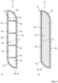
- FIG. 3 to 5 shows various embodiments of a closure blade 12 according to the invention, with a variant with a web-shaped reinforcement element 16 being shown in the left-hand half of the figure labeled a) and an alternative variant with a reinforcement element 16 designed as a foam core being shown in the right-hand half of the figure labeled b).
- the Figure 3a shows a cross section of a closure blade 12 with a hollow body 14 and a bar-shaped reinforcing element 16 arranged in its interior, which here comprises four bars 18 1 to 18 4 .
- the outer circumference of the hollow body 14 forms the shape of a parallelogram with pairs of opposite longitudinal sides 20 1 , 20 2 or transverse sides 22 1 , 22 2 .
- the webs 18 1 to 18 4 run parallel and spaced evenly from one another and connect the longitudinal sides 20 1 , 20 2 to one another.
- the arrangement of the webs 18 1 to 18 4 is such that the webs 18 1 , 18 2 with the longitudinal sides 20 1 , 20 2 and the webs 18 2 , 18 3 with the longitudinal sides 20 1 , 20 2 and the webs 18 3 , 18 4 with the longitudinal sides 20 1 , 20 2 enclosing respectively right-angled volume elements 24 1 , 24 2 , 24 3 .
- the web 18 1 , the transverse side 22 1 , the longitudinal side 20 2 and the web 18 4 , the transverse side 22 2 , the longitudinal side 20 3 each enclose triangular volume elements 26 1 , 26 2 .
- a guide element 40 , 42 is indicated by a dot-dash line around the hollow body 14 .
- the Figure 3b shows a cross section of a closure lamella 12 with a hollow body 14 and a reinforcing element 16 arranged in its interior, which is present as a foam core 28 of the Hollow body 14 is formed.
- the foam core 28 completely fills the interior of the hollow body 14 .
- the foam core 28 would also be conceivable for the foam core 28 to leave out certain areas of the interior of the hollow body 14 .
- the foam core has a varying density, for example more solid and denser in areas close to the hollow body 14.
- the hollow body 14 can be made of either GRP or CFRP.
- FIGS. 4a) and 4b ) show a further embodiment of a closure blade 12 according to the invention, compared to the embodiment of FIG Figures 3a) and 3b ) only the hollow body 14 has been changed in such a way that it now has a rectangular shape, as a special form of a parallelogram, so that in the variant with the bar-shaped reinforcing element 16 only two bars 18 1 and 18 2 and also no triangular volume elements are provided.
- FIGS 5a) and 5b show a further embodiment of a closure blade 12 according to the invention, this being basically one of the embodiment according to FIG Figures 3a) and 3b ) have a comparable basic form. Only the transverse sides 22 1 and 22 2 are designed as curved edges of the hollow body 14 .
- FIGS. 6a) and 6b ) show the embodiment according to Figures 3a) and 3b ) with metal rails 44 1 , 44 2 attached in the area of the acute angle between the longitudinal sides 20 1 , 20 2 and transverse sides 22 1 , 22 2 , which can be used to attach a grounding strap - not shown - to the hull of the watercraft.
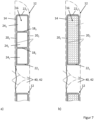
- FIGS 7a) and 7b ) show the embodiment according to Figures 4a) and 4b ) in an assembly of two closure lamellae 12. It can be seen that on one side between the two closure lamellae 12 shown, a fabric web 46 for sealing against ambient water is arranged.
- the fabric panel 46 can be made of a fabric reinforced by a steel mesh, for example.
- FIGS 8a) and 8b ) show the embodiment according to Figures 3a) and 3b ) in an assembly of two closure lamellae 12.
- a seal is provided between two closure lamellae 12 shown for sealing against ambient water.
- the seal is formed by a seal 48 in the area of the acute angle between longitudinal sides 20 1 , 20 2 and transverse sides 22 1 , 22 2 of the adjacent closure lamellae 12 .
- the figure 9 shows a perspective view of one of the guide elements 40, 42, via which the closure plate 12 can be held in the outer skin opening 4 of the watercraft 2.
- the Guide element 40, 42 has a sliding shoe 54, via which it is guided in the respective guide rail 50, 52. Furthermore, the guide element 40, 42 has a retaining collar 56 attached perpendicularly to the sliding shoe 54, via which the guide element 40, 42 can be inserted and fastened into the hollow body 14 at opposite ends of the shutter blade 12.
- the guide element 40, 42 can be fastened to or in the hollow body 14 via the holding collar 56, for example by means of an adhesive bond.
- positive-locking elements are provided on the retaining collar 56, which are latched to the hollow body in a suitable manner. Screwing the retaining collar 56 to the hollow body 14 is also conceivable.
Landscapes
- Engineering & Computer Science (AREA)
- Aviation & Aerospace Engineering (AREA)
- Chemical & Material Sciences (AREA)
- Combustion & Propulsion (AREA)
- Mechanical Engineering (AREA)
- Ocean & Marine Engineering (AREA)
- Operating, Guiding And Securing Of Roll- Type Closing Members (AREA)
- Fertilizing (AREA)
- Vehicle Step Arrangements And Article Storage (AREA)
- Closures For Containers (AREA)
Description
- Die Erfindung betrifft ein Wasserfahrzeug mit einer Verschlusslamelle zum Verschließen einer Au-ßenhautöffnung des Wasserfahrzeugs. Ein Wasserfahrzeug mit einer Außenhautöffnung und mit einer Verschlussvorrichtung sind z.B. aus
JP 2004027739 EP 2433859 bekannt. - Bei Wasserfahrzeugen, beispielsweise militärisch genutzten Überwasserschiffen, sind regelmäßig innerhalb der Außenhaut des Schiffes angeordnete Räume vorgesehen, die als Stauraum für Beiboote vorgesehen sein können, um diese bei Bedarf zu Wasser lassen zu können. Es können Verschlussvorrichtungen vorgesehen sein, um diese Räume zu verschließen, wenn kein Zugang erforderlich ist. Eine Verschlussvorrichtung kann über ein torartiges Verschlusselement oder aber über mehrere parallel zueinander angeordnete Verschlusslamellen verfügen, um die Außenhautöffnung zu verschließen beziehungsweise abzudecken. Verschlusslamellen haben bei entsprechender Anordnung zueinander und Gestaltung der Schließmechanik der Verschlussvorrichtung den Vorteil, dass sie in der geöffneten Position platzsparend angeordnet werden können. Verschlusslamellen stellen allerdings bestimmte Anforderungen an der Festigkeit und die Art und Weise der Ankopplung der Verschlusslamellen an die Schließmechanik der Verschlussvorrichtung. Weiterhin ist bei der Formgebung der Außenkontur der Verschlusslamellen darauf zu achten, dass jeweils benachbarte Verschlusslamellen derart komplementär zueinander sind, dass sie beim Öffnen der Verschlussvorrichtung sich gegeneinander bewegen können, um geöffnet einen möglichst kleinen Raum einzunehmen.
- Ausgehend hiervon besteht die Aufgabe der vorliegenden Erfindung darin, eine Verschlusslamelle bereitzustellen, die oben skizzierten Anforderungen Rechnung trägt.
- Die Aufgabe wird gelöst durch das Wasserfahrzeug mit einer Verschlusslamelle zum Verschließen einer Außenhautöffnung des Wasserfahrzeugs, umfassend einen Hohlkörper mit zumindest einem im Inneren des Hohlkörpers angeordneten Verstärkungselement, wobei ein Außenumfang einer Querschnittfläche des Hohlkörpers durch zwei parallele Längskanten und zwei die Längskanten an ihren Enden verbindende punktsymmetrisch zueinander angeordneten Querkanten gebildet wird. Eine erfindungsgemäße Verschlusslamelle hat eine Längsausdehnung entlang einer Längsrichtung L. Unter einer Querschnittsfläche des Hohlkörpers ist demnach bezogen auf diese Längsrichtung L eine Fläche in einer Ebene zu verstehen, bei der die Längsrichtung L die Flächennormale der Querschnittsfläche bildet. Erfindungsgemäß sind senkrecht beziehungsweise vertikal stehende Verschlusslamellen vorgesehen. Der eine Querschnittsfläche ist in einer horizontalen Ebene angeordnet. Bevorzugt ist bei eine derartigen Anordnung der Verschlusslamellen vorgesehen, dass eine vertikale Ausdehnung einer Verschlusslamelle 2000 mm nicht unterschreitet.
- Eine vorteilhafte Ausgestaltung der Erfindung sieht vor, dass der Hohlkörper aus einem GFK-, CFK-, Stahl-, oder Aluminiumwerkstoff hergestellt beziehungsweise gefertigt ist. Hierdurch sind die Verschlusslamellen in Leichtbauweise herzustellen, wobei sich über das Verstärkungselement die nötige Festigkeit gewährleisten lässt, damit die Verschlusslamellen in der Lage ist den auftretenden Belastungen standzuhalten.
- Erfindungsgemäß sieht vor, dass das zumindest eine Verstärkungselement einen stegförmigen Verlauf hat. Über eine geeignete Gestaltung des stegförmigen Verlaufs lässt sich die Festigkeit der Verschlusslamelle gezielt auf die zu erwartenden Belastungen auslegen.
- Eine alternative Ausgestaltung der Erfindung sieht vor, dass das zumindest eine Verstärkungselement als Schaumkern des Hohlkörpers ausgebildet ist. Das vorsehen eines Schaumkerns bieten fertigungstechnische Vorteile, da hier der Hohlkörper lediglich gleichmäßig ausgeschäumt werden muss.
- Eine vorteilhafte Ausgestaltung der Erfindung sieht vor, dass der Außenumfang der Querschnittfläche des Hohlkörpers mit den Längskanten und den Querkanten ein Parallelogramm beschreibt. Hierbei ist insbesondere vorgesehen, dass gegenüberliegende Innenwinkel des Parallelogramms 40° - 90° betragen. Hierdurch lassen sich benachbarte Verschlusslamellen derart geometrisch aufeinander abstimmen, dass sie sich beim Öffnen der Verschlussvorrichtung gegeneinander bewegen können.
- Erfindungsgemäß ist vorgesehen, dass voneinander abgewandte Stirnseiten des Hohlkörpers zur Befestigung eines Führungselements ausgebildet sind, um über das Führungselement die Verschlusslamelle in der Außenhautöffnung des Wasserfahrzeugs zu halten. Hierdurch wird eine Schnittstelle geschaffen, über die die Verschlusslamellen bedarfsweise mit unterschiedlichen Führungselementen ausgestattet werden können. Die Führungselemente können von der Schließmechanik beaufschlagt werden und übertragen eine Öffnungsbewegung oder eine Schließbewegung auf die Verschlusslamellen.
- Erfindungsgemäß ist vorgesehen, dass das Führungselement in den Hohlkörper einschiebbar ausgebildet ist. Bevorzugt umschließt der Hohlkörper das Führungselement bündig und umfängliche, wenn das Führungselement in de Hohlkörper eingeschoben ist.
- Eine vorteilhafte Ausgestaltung der Erfindung sieht vor, dass zwischen voneinander abgewandten Stirnseiten des Hohlkörpers verlaufende Kantenbereiche des Hohlkörpers Radien mit einem Maß zwischen 5 mm und 50 mm ausbilden. Auch hierdurch lassen sich benachbarte Verschlusslamellen derart geometrisch aufeinander abstimmen, dass sie sich beim Öffnen der Verschlussvorrichtung gegeneinander bewegen können.
- Die Erfindung wird nachfolgend mit weiteren Merkmalen, Einzelheiten und Vorteilen anhand der beigefügten Figuren erläutert. Die Figuren illustrieren dabei lediglich beispielhafte Ausführungsformen der Erfindung. Hierin zeigen
- Figur 1
- ein Überwasserschiff mit zwei Außenhautöffnungen und diese abdeckende Verschlussvorrichtungen;
- Figur 2
- eine perspektivische Ansicht einer Verschlussvorrichtung:
- Figuren 3a, 3b
- eine Ausführungsform einer erfindungsgemäßen Verschlusslamelle;
- Figuren 3a, 3b
- eine weitere Ausführungsform einer erfindungsgemäßen Verschlusslamelle;
- Figuren 4a, 4b
- eine weitere Ausführungsform einer erfindungsgemäßen Verschlusslamelle;
- Figuren 5a, 5b
- eine weitere Ausführungsform einer erfindungsgemäßen Verschlusslamelle;
- Figuren 6a, 6b
- ein optionales Detail der Ausführungsform gemäß
Figuren 3a, 3b ; - Figuren 7a, 7b
- ein Zusammenbau von zwei Verschlusslamellen der Ausführungsform gemäß
Figuren 4a, 4b und - Figuren 8a, 8b
- ein Zusammenbau von zwei Verschlusslamellen der Ausführungsform gemäß
Figuren 3a, 3b - Die
Figur 1 zeigt ein Überwasserschiff 2 in Gestalt eines Marineschiffes. Oberhalb einer nicht weiter gekennzeichneten Wasseroberfläche weist das Überwasserschiff 2 zwei Außenhautöffnungen 4 auf, wobei diese Anzahl vorliegend als exemplarisch anzusehen ist. Die Außenhautöffnungen 4 sind mit jeweils einer Verschlussvorrichtung 10 abgedeckt, wobei die Verschlussvorrichtung 10 zwischen einer vorliegend dargestellten Schließposition und einer Öffnungsposition bewegt werden kann. Hierzu weist die Verschlussvorrichtung 10 mehrere im Wesentlichen senkrecht ausgerichtete und bewegbare erfindungsgemäße Verschlusslamellen 12 auf. Vorliegend ist eine Verschlussvorrichtung 10 rein exemplarisch mit acht Verschlusslamellen 12 dargestellt, wobei jede hiervon abweichende Anzahl vorgesehen sein kann. Bevorzugt ist allerdings, dass eine gerade Anzahl an Verschlusslamellen 12 vorgesehen ist. Weiterhin ist bevorzugt, dass sich die Verschlusslamellen 12 zu gleichen Teilen zu entgegengesetzten Seiten der Außenhautöffnung 4 in die Öffnungsposition verschieben lassen, das heißt ausgehend von der Schließposition die Außenhautöffnung 4 mittig freigeben und zu den Seiten der Außenhautöffnung 4 in die Öffnungsposition verfahren. - Die
Figur 2 zeigt die Verschlussvorrichtung 10 in einer schematischen und nicht maßstabsgetreuen Darstellung. Gezeigt ist eine Antriebsvorrichtung 30, eine obere und die untere Führungsschiene 50, 52 und zwei Verschlusslamellen 121 und 121'. Bei den beiden Verschlusslamellen 121, 121' handelt es sich um die jeweils erste Verschlusslamelle 12 der beiden Hälften der Verschlussvorrichtung 10, die bevorzugt zu gleichen Teilen zu entgegengesetzten Seiten der Außenhautöffnung 4 öffnen. Die beiden Verschlusslamellen 121, 121' können hierzu von der Antriebsvorrichtung 30 zu den entgegengesetzten Seiten in die Öffnungsposition bewegt werden. Die Antriebsvorrichtung 30 umfasst eine obere 321 und eine untere Rollenkette 322, Antriebsmittel 34 beispielsweise in Form eines Elektromotors oder eines Pneumatikmotors zum Antrieb der Rollenketten 321, 322 und zwei Umlenkungen 36, 38 an entgegengesetzten Seiten der Verschlussvorrichtung 10, über die die Rollenketten 321, 322 geführt sind. Hierbei ist die Umlenkung 36 durch die Antriebsmittel 34 angetrieben und die andere Umlenkung 38 passiv ausgeführt. Über die Umlenkung 36 sind die beiden Rollenketten 321, 322 angetrieben. Beide Rollenketten 321, 322 sind als Endlosketten gestaltet und jeweils mit den beiden Verschlusslamellen 121 und 121' antriebsmäßig verbunden. Hierbei ist die obere Rollenkette 321 mit oberen Führungselementen 401 und 401' und die untere Rollenkette 322 mit unteren Führungselementen 421 und 421' der Verschlusslamellen 121, 121' verbunden. Weiterhin ist mit einer strichpunktierten Linie die Längsrichtung L der Verschlusslamellen 12 gekennzeichnet. - Die
Figuren 3 bis 5 zeigt verschiedene Ausführungsformen einer erfindungsgemäßen Verschlusslamelle 12, wobei in der jeweils linken mit a) bezeichneten Bildhälfte eine Variante mit stegförmig ausgebildetem Verstärkungselement 16 und in der jeweils rechten mit b) bezeichneten Bildhälfte eine alternative Variante mit als Schaumkern ausgebildetem Verstärkungselement 16 gezeigt ist. - Die
Figur 3a ) zeigt einen Querschnitt einer Verschlusslamelle 12 mit einem Hohlkörper 14 und ein in dessen Innerem angeordnetes stegförmiges Verstärkungselement 16, das vorliegend vier Stege 181 bis 184 umfasst. Der Außenumfang des Hohlkörpers 14 bildet die Form eines Parallelogramms mit paarweise gegenüberliegenden Längsseiten 201, 202 beziehungsweise Querseiten 221, 222. Die Stege 181 bis 184 verlaufen parallel und gleichmäßig beabstandet zueinander und verbinden jeweils die Längsseiten 201, 202 miteinander. Die Anordnung der Stege 181 bis 184 ist derart getroffen, dass die Stege 181, 182 mit den Längsseiten 201, 202 und die Stege 182, 183 mit den Längsseiten 201, 202 und die Stege 183, 184 mit den Längsseiten 201, 202 jeweils rechtwinklige Volumenelemente 241, 242, 243 einschließen. Außerdem schließen der Steg 181, die Querseite 221, die Längsseite 202 und der Steg 184, die Querseite 222, die Längsseite 203 jeweils dreieckige Volumenelemente 261, 262 ein. Weiterhin ist mit einer strichpunktierten Linie um den Hohlkörper 14 herum ein Führungselement 40, 42 angedeutet. - Die
Figur 3b ) zeigt einen Querschnitt einer Verschlusslamelle 12 mit einem Hohlkörper 14 und ein in dessen Innerem angeordnetes Verstärkungselement 16, das vorliegend als Schaumkern 28 des Hohlkörpers 14 ausgebildet ist. Hierbei kann vorgesehen sein, dass der Schaumkern 28 das Innere des Hohlkörpers 14 vollständig ausfüllt. Denkbar wäre auch, dass der Schaumkern 28 gewisse Bereiche des Inneren des Hohlkörpers 14 ausspart. Weiterhin ist denkbar, dass der Schaumkern eine variierende Dichte aufweist, beispielsweise fester und dichter in Bereichen nahe des Hohlkörpers 14. Der Hohlkörper 14 kann wahlweise aus GFK oder CFK gefertigt sein. - Die
Figuren 4a) und 4b ) zeigen eine weitere Ausführungsform einer erfindungsgemäßen Verschlusslamelle 12, wobei gegenüber der Ausführungsform derFiguren 3a) und 3b ) lediglich der Hohlkörper 14 dahingehend geändert wurde, dass dieser nunmehr eine rechteckige Form, als Sonderform eines Parallelogramms, ausbildet, so dass bei der Varianten mit dem stegförmigen Verstärkungselement 16 nur zwei Stege 181 und 182 und außerdem keine dreieckigen Volumenelemente vorgesehen sind. - Die
Figuren 5a) und 5b ) zeigen eine weitere Ausführungsform einer erfindungsgemäßen Verschlusslamelle 12, wobei diese grundsätzlich eine zu der Ausführungsform gemäßFiguren 3a) und 3b ) vergleichbare Grundform habe. Lediglich die Querseiten 221 und 222 sind als gebogene Kanten des Hohlkörpers 14 ausgeführt. - Die
Figuren 6a) und 6b ) zeigen die Ausführungsform gemäßFiguren 3a) und 3b ) mit im Bereich des spitzen Winkels zwischen Längsseiten 201, 202 und Querseiten 221, 222 angebrachten Metallschienen 441, 442, die als Befestigungsmöglichkeit für ein Erdungsband - nicht dargestellt - zum Rumpf des Wasserfahrzeugs dienen können. - Die
Figuren 7a) und 7b ) zeigen die Ausführungsform gemäßFiguren 4a) und 4b ) in einem Zusammenbau von zwei Verschlusslamellen 12. Zu erkennen ist, dass auf einer Seite zwischen den zwei dargestellten Verschlusslamellen 12 eine Stoffbahn 46 zur Abdichtung gegen Umgebungswasser angeordnet ist. Die Stoffbahn 46 kann beispielsweise aus einem durch ein Stahlgewebe verstärkten Stoff hergestellt sein. - Die
Figuren 8a) und 8b ) zeigen die Ausführungsform gemäßFiguren 3a) und 3b ) in einem Zusammenbau von zwei Verschlusslamellen 12. Auch hier ist eine Abdichtung zwischen zwei dargestellten Verschlusslamellen 12 zur Abdichtung gegen Umgebungswasser vorgesehen. Die Abdichtung wird durch eine Dichtung 48 im Bereich des spitzen Winkels zwischen Längsseiten 201, 202 und Querseiten 221, 222 der benachbarten Verschlusslamellen 12 gebildet. - Die
Figur 9 zeigt in perspektivischer Ansicht eins der Führungselemente 40, 42, über die die Verschlusslamelle 12 in der Außenhautöffnung 4 des Wasserfahrzeugs 2 gehalten werden kann. Das Führungselement 40, 42 weist einen Gleitschuh 54 auf, über den es in der jeweiligen Führungsschiene 50, 52 geführt ist. Weiterhin weist das Führungselement 40, 42 einen senkrecht auf dem Gleitschuh 54 angebrachten Haltekragen 56 auf, über den das Führungselement 40, 42 in den Hohlkörper 14 an entgegengesetzten Enden der Verschlusslamelle 12 eingeschoben und befestigt werden kann. Über den Haltekragen 56 kann das Führungselement 40, 42 beispielsweise über eine Verklebung an beziehungsweise in dem Hohlkörper 14 befestigt werden. Alternativ oder zusätzlich ist denkbar, dass Formschlusselemente an dem Haltekragen 56 vorgesehen sind, die in geeigneter Weise mit dem Hohlkörper verrastet werden. Denkbar ist auch eine Verschraubung des Haltekragens 56 an dem Hohlkörper 14. -
- 2
- Überwasserschiff
- 4
- Außenhautöffnung
- 10
- Verschlussvorrichtung
- 12
- Verschlusslamelle
- 14
- Hohlkörper
- 16
- Verstärkungselement
- 18
- Steg
- 20
- Längsseite
- 22
- Querseite
- 24
- Volumenelement
- 26
- Volumenelement
- 28
- Schaumkern
- 30
- Antriebsvorrichtung
- 32
- Rollenkette
- 34
- Antriebsmittel
- 36
- Umlenkungen
- 38
- Umlenkungen
- 40
- Führungselement
- 42
- Führungselement
- 44
- Metallschiene
- 46
- Stoffbahn
- 50
- Führungsschiene
- 52
- Führungsschiene
- 54
- Gleitschuh
- 56
- Haltekragen
- L
- Längsrichtung
Claims (8)
- Wasserfahrzeug (2) mit einer Außenhautöffnung (4) und einer Verschlusslamelle (12) zum Verschließen der Außenhautöffnung (4) des Wasserfahrzeugs (2), umfassendeinen Hohlkörper (14) mit zumindest einem im Inneren des Hohlkörpers (14) angeordneten stegförmig verlaufenden Verstärkungselement (16),wobei ein Außenumfang einer Querschnittfläche des Hohlkörpers (14) durch zwei parallele Längskanten (201, 202) und zwei die Längskanten (201, 202) an ihren Enden verbindende punktsymmetrisch zueinander angeordneten Querkanten (221, 222) gebildet wird, wobei in den Hohlkörper (14) einschiebbar ausgebildete Führungselemente (40, 42) vorgesehen sind und voneinander abgewandte Stirnseiten des Hohlkörpers (14) zur Befestigung jeweils eines der Führungselemente (40, 42) ausgebildet sind, um über das Führungselement (40, 42) die Verschlusslamelle (12) in der Außenhautöffnung (4) des Wasserfahrzeugs (2) zu halten, wobei die Verschlusslamellen senkrecht stehend angeordnet sind.
- Wasserfahrzeug (2) nach Anspruch 1, dadurch gekennzeichnet, dass der Hohlkörper (14) eine radarstrahlenreflektierende Oberfläche aufweist.
- Wasserfahrzeug (2) nach Anspruch 2, dadurch gekennzeichnet, dass die Oberfläche durch eine metallische Folie oder eine metallische Gitterstruktur gebildet wird.
- Wasserfahrzeug (2) nach einem der Ansprüche 1 bis 3, dadurch gekennzeichnet, dass der Hohlkörper (14) aus einem GFK-, CFK-, Stahl-, oder Aluminiumwerkstoff hergestellt ist.
- Wasserfahrzeug (2) nach einem der Ansprüche 1 bis 4, dadurch gekennzeichnet, dass das zumindest eine Verstärkungselement (16) als Schaumkern (28) des Hohlkörpers (14) ausgebildet ist.
- Wasserfahrzeug (2) nach einem der Ansprüche 1 bis 5, dadurch gekennzeichnet, dass der Außenumfang der Querschnittfläche des Hohlkörpers (14) mit den Längskanten und den Querkanten ein Parallelogramm beschreibt.
- Wasserfahrzeug (2) nach Anspruch 6, dadurch gekennzeichnet, dass gegenüberliegende Innenwinkel des Parallelogramms 40° - 90° betragen.
- Wasserfahrzeug (2) nach einem der Ansprüche 1 bis 7, dadurch gekennzeichnet, dass zwischen voneinander abgewandten Stirnseiten des Hohlkörpers (14) verlaufende Kantenbereiche des Hohlkörpers (14) Radien mit einem Maß zwischen 5 mm und 50 mm ausbilden.
Applications Claiming Priority (2)
| Application Number | Priority Date | Filing Date | Title |
|---|---|---|---|
| DE102016221146.3A DE102016221146A1 (de) | 2016-10-27 | 2016-10-27 | Verschlusslamelle |
| PCT/EP2017/077253 WO2018077924A1 (de) | 2016-10-27 | 2017-10-25 | Verschlusslamelle |
Publications (3)
| Publication Number | Publication Date |
|---|---|
| EP3532372A1 EP3532372A1 (de) | 2019-09-04 |
| EP3532372B1 true EP3532372B1 (de) | 2023-06-07 |
| EP3532372C0 EP3532372C0 (de) | 2023-06-07 |
Family
ID=60320834
Family Applications (1)
| Application Number | Title | Priority Date | Filing Date |
|---|---|---|---|
| EP17797548.9A Active EP3532372B1 (de) | 2016-10-27 | 2017-10-25 | Verschlusslamelle |
Country Status (4)
| Country | Link |
|---|---|
| EP (1) | EP3532372B1 (de) |
| DE (1) | DE102016221146A1 (de) |
| ES (1) | ES2954852T3 (de) |
| WO (1) | WO2018077924A1 (de) |
Family Cites Families (8)
| Publication number | Priority date | Publication date | Assignee | Title |
|---|---|---|---|---|
| DE7641171U1 (de) * | 1976-12-31 | 1979-06-28 | Rupprecht, Josef, 8700 Wuerzburg | Lamellenfenster |
| JP2004027739A (ja) * | 2002-06-27 | 2004-01-29 | Mitsubishi Heavy Ind Ltd | 艦船用格納庫 |
| DE10250284A1 (de) * | 2002-10-29 | 2004-05-13 | Otto Volz | Elementtor |
| DE102004035640A1 (de) * | 2004-07-22 | 2006-02-16 | Kuhlgatz, Klaus | Boot mit einem Verschluss für eine Einstiegsöffnung |
| DE202007013192U1 (de) * | 2007-09-20 | 2008-02-28 | Lacker, Herbert | Lamellenfläche |
| DE102010046608B4 (de) * | 2010-09-25 | 2012-07-26 | Howaldtswerke-Deutsche Werft Gmbh | Vorrichtung zum Verschließen einer seitlichen Öffnung in der Außenhaut oder Wandung eines Boots |
| DE102014212867A1 (de) * | 2014-07-02 | 2016-01-07 | Klimasky Gmbh | Lamelle für ein Lamellendach oder ein Lamellenfenster sowie Lamellendach oder Lamellenfenster mit einer solchen Lamelle |
| DE102015202551A1 (de) * | 2015-02-12 | 2016-08-18 | Thyssenkrupp Ag | Faltbarer RCS Behälter |
-
2016
- 2016-10-27 DE DE102016221146.3A patent/DE102016221146A1/de not_active Withdrawn
-
2017
- 2017-10-25 WO PCT/EP2017/077253 patent/WO2018077924A1/de not_active Ceased
- 2017-10-25 ES ES17797548T patent/ES2954852T3/es active Active
- 2017-10-25 EP EP17797548.9A patent/EP3532372B1/de active Active
Also Published As
| Publication number | Publication date |
|---|---|
| EP3532372A1 (de) | 2019-09-04 |
| DE102016221146A1 (de) | 2018-05-03 |
| WO2018077924A1 (de) | 2018-05-03 |
| ES2954852T3 (es) | 2023-11-27 |
| EP3532372C0 (de) | 2023-06-07 |
Similar Documents
| Publication | Publication Date | Title |
|---|---|---|
| DE2134134A1 (de) | Schottur Anordnung | |
| EP3271242B1 (de) | Montageeinrichtung | |
| DE102011100345B3 (de) | Schaltschrank | |
| DE102018120371B4 (de) | Batteriegehäuse für ein elektromotorisch angetriebenes Fahrzeug | |
| DE102014107404A1 (de) | Druckschott für einen Flugzeugrumpf | |
| EP4309241B1 (de) | Antennenverkleidung für flugzeuge | |
| DE102010028490B4 (de) | Flügelprofil mit veränderlicher Krümmung | |
| DE1755580C2 (de) | Kraftstofftank für Fahrzeuge | |
| DE102009056533B4 (de) | Flugzeugrumpfbauteil | |
| DE2701905B2 (de) | Stranggepreßtes Bauelement zum Aufbau von Wänden, insbesondere von Kraftfahrzeugen | |
| EP3087337B1 (de) | Wärmetauscher mit umlaufender dichtung | |
| EP3532372B1 (de) | Verschlusslamelle | |
| DE102004031466B4 (de) | Vorrichtung zur Aufnahme von Gütern | |
| EP0502361A1 (de) | Grabenverbauvorrichtung | |
| EP2826650B1 (de) | Rahmen eines Fahrzeugschiebedachs mit Kabelkanälen | |
| EP2653641B1 (de) | Kettenantrieb | |
| DE102005061127A1 (de) | Luftfahrzeugtür-Anordnung sowie Luftfahrzeugrumpf mit einer derartigen Luftfahrzeugtür-Anordnung | |
| EP0415025A2 (de) | Abdeckband | |
| DE202009008378U1 (de) | Laserschutzwand | |
| EP0461336A2 (de) | Verfahren zur Herstellung einer Druckkammer mit Widerstandfähigkeit gegen innere Detonationen, und gemäss diesem Verfahren hergestellte Druckkammer | |
| EP0407482B1 (de) | Konstruktionsprofil | |
| EP3468861B1 (de) | Verschlussvorrichtung | |
| DE102009053568A1 (de) | Führungsprofil und Linearmotorantriebseinrichtung | |
| EP1771276B1 (de) | Abdeckvorrichtung | |
| DE102009004811A1 (de) | Vorrichtung zum Verriegeln einer Passagiertür |
Legal Events
| Date | Code | Title | Description |
|---|---|---|---|
| STAA | Information on the status of an ep patent application or granted ep patent |
Free format text: STATUS: UNKNOWN |
|
| STAA | Information on the status of an ep patent application or granted ep patent |
Free format text: STATUS: THE INTERNATIONAL PUBLICATION HAS BEEN MADE |
|
| PUAI | Public reference made under article 153(3) epc to a published international application that has entered the european phase |
Free format text: ORIGINAL CODE: 0009012 |
|
| STAA | Information on the status of an ep patent application or granted ep patent |
Free format text: STATUS: REQUEST FOR EXAMINATION WAS MADE |
|
| 17P | Request for examination filed |
Effective date: 20190527 |
|
| AK | Designated contracting states |
Kind code of ref document: A1 Designated state(s): AL AT BE BG CH CY CZ DE DK EE ES FI FR GB GR HR HU IE IS IT LI LT LU LV MC MK MT NL NO PL PT RO RS SE SI SK SM TR |
|
| AX | Request for extension of the european patent |
Extension state: BA ME |
|
| RAP1 | Party data changed (applicant data changed or rights of an application transferred) |
Owner name: THYSSENKRUPP MARINE SYSTEMS GMBH Owner name: THYSSENKRUPP AG |
|
| DAV | Request for validation of the european patent (deleted) | ||
| DAX | Request for extension of the european patent (deleted) | ||
| STAA | Information on the status of an ep patent application or granted ep patent |
Free format text: STATUS: EXAMINATION IS IN PROGRESS |
|
| 17Q | First examination report despatched |
Effective date: 20200901 |
|
| RAP3 | Party data changed (applicant data changed or rights of an application transferred) |
Owner name: THYSSENKRUPP AG Owner name: THYSSENKRUPP MARINE SYSTEMS GMBH |
|
| GRAP | Despatch of communication of intention to grant a patent |
Free format text: ORIGINAL CODE: EPIDOSNIGR1 |
|
| STAA | Information on the status of an ep patent application or granted ep patent |
Free format text: STATUS: GRANT OF PATENT IS INTENDED |
|
| INTG | Intention to grant announced |
Effective date: 20221111 |
|
| GRAS | Grant fee paid |
Free format text: ORIGINAL CODE: EPIDOSNIGR3 |
|
| GRAA | (expected) grant |
Free format text: ORIGINAL CODE: 0009210 |
|
| STAA | Information on the status of an ep patent application or granted ep patent |
Free format text: STATUS: THE PATENT HAS BEEN GRANTED |
|
| AK | Designated contracting states |
Kind code of ref document: B1 Designated state(s): AL AT BE BG CH CY CZ DE DK EE ES FI FR GB GR HR HU IE IS IT LI LT LU LV MC MK MT NL NO PL PT RO RS SE SI SK SM TR |
|
| REG | Reference to a national code |
Ref country code: GB Ref legal event code: FG4D Free format text: NOT ENGLISH |
|
| REG | Reference to a national code |
Ref country code: CH Ref legal event code: EP Ref country code: AT Ref legal event code: REF Ref document number: 1574226 Country of ref document: AT Kind code of ref document: T Effective date: 20230615 |
|
| REG | Reference to a national code |
Ref country code: DE Ref legal event code: R096 Ref document number: 502017014887 Country of ref document: DE |
|
| U01 | Request for unitary effect filed |
Effective date: 20230707 |
|
| U07 | Unitary effect registered |
Designated state(s): AT BE BG DE DK EE FI FR IT LT LU LV MT NL PT SE SI Effective date: 20230719 |
|
| REG | Reference to a national code |
Ref country code: LT Ref legal event code: MG9D |
|
| PG25 | Lapsed in a contracting state [announced via postgrant information from national office to epo] |
Ref country code: NO Free format text: LAPSE BECAUSE OF FAILURE TO SUBMIT A TRANSLATION OF THE DESCRIPTION OR TO PAY THE FEE WITHIN THE PRESCRIBED TIME-LIMIT Effective date: 20230907 |
|
| REG | Reference to a national code |
Ref country code: ES Ref legal event code: FG2A Ref document number: 2954852 Country of ref document: ES Kind code of ref document: T3 Effective date: 20231127 |
|
| U20 | Renewal fee for the european patent with unitary effect paid |
Year of fee payment: 7 Effective date: 20231024 |
|
| PG25 | Lapsed in a contracting state [announced via postgrant information from national office to epo] |
Ref country code: RS Free format text: LAPSE BECAUSE OF FAILURE TO SUBMIT A TRANSLATION OF THE DESCRIPTION OR TO PAY THE FEE WITHIN THE PRESCRIBED TIME-LIMIT Effective date: 20230607 Ref country code: HR Free format text: LAPSE BECAUSE OF FAILURE TO SUBMIT A TRANSLATION OF THE DESCRIPTION OR TO PAY THE FEE WITHIN THE PRESCRIBED TIME-LIMIT Effective date: 20230607 Ref country code: GR Free format text: LAPSE BECAUSE OF FAILURE TO SUBMIT A TRANSLATION OF THE DESCRIPTION OR TO PAY THE FEE WITHIN THE PRESCRIBED TIME-LIMIT Effective date: 20230908 |
|
| PG25 | Lapsed in a contracting state [announced via postgrant information from national office to epo] |
Ref country code: SK Free format text: LAPSE BECAUSE OF FAILURE TO SUBMIT A TRANSLATION OF THE DESCRIPTION OR TO PAY THE FEE WITHIN THE PRESCRIBED TIME-LIMIT Effective date: 20230607 |
|
| PG25 | Lapsed in a contracting state [announced via postgrant information from national office to epo] |
Ref country code: IS Free format text: LAPSE BECAUSE OF FAILURE TO SUBMIT A TRANSLATION OF THE DESCRIPTION OR TO PAY THE FEE WITHIN THE PRESCRIBED TIME-LIMIT Effective date: 20231007 |
|
| PG25 | Lapsed in a contracting state [announced via postgrant information from national office to epo] |
Ref country code: SM Free format text: LAPSE BECAUSE OF FAILURE TO SUBMIT A TRANSLATION OF THE DESCRIPTION OR TO PAY THE FEE WITHIN THE PRESCRIBED TIME-LIMIT Effective date: 20230607 Ref country code: SK Free format text: LAPSE BECAUSE OF FAILURE TO SUBMIT A TRANSLATION OF THE DESCRIPTION OR TO PAY THE FEE WITHIN THE PRESCRIBED TIME-LIMIT Effective date: 20230607 Ref country code: RO Free format text: LAPSE BECAUSE OF FAILURE TO SUBMIT A TRANSLATION OF THE DESCRIPTION OR TO PAY THE FEE WITHIN THE PRESCRIBED TIME-LIMIT Effective date: 20230607 Ref country code: IS Free format text: LAPSE BECAUSE OF FAILURE TO SUBMIT A TRANSLATION OF THE DESCRIPTION OR TO PAY THE FEE WITHIN THE PRESCRIBED TIME-LIMIT Effective date: 20231007 Ref country code: CZ Free format text: LAPSE BECAUSE OF FAILURE TO SUBMIT A TRANSLATION OF THE DESCRIPTION OR TO PAY THE FEE WITHIN THE PRESCRIBED TIME-LIMIT Effective date: 20230607 |
|
| PG25 | Lapsed in a contracting state [announced via postgrant information from national office to epo] |
Ref country code: PL Free format text: LAPSE BECAUSE OF FAILURE TO SUBMIT A TRANSLATION OF THE DESCRIPTION OR TO PAY THE FEE WITHIN THE PRESCRIBED TIME-LIMIT Effective date: 20230607 |
|
| REG | Reference to a national code |
Ref country code: DE Ref legal event code: R097 Ref document number: 502017014887 Country of ref document: DE |
|
| PLBE | No opposition filed within time limit |
Free format text: ORIGINAL CODE: 0009261 |
|
| STAA | Information on the status of an ep patent application or granted ep patent |
Free format text: STATUS: NO OPPOSITION FILED WITHIN TIME LIMIT |
|
| 26N | No opposition filed |
Effective date: 20240308 |
|
| PG25 | Lapsed in a contracting state [announced via postgrant information from national office to epo] |
Ref country code: MC Free format text: LAPSE BECAUSE OF FAILURE TO SUBMIT A TRANSLATION OF THE DESCRIPTION OR TO PAY THE FEE WITHIN THE PRESCRIBED TIME-LIMIT Effective date: 20230607 |
|
| REG | Reference to a national code |
Ref country code: CH Ref legal event code: PL |
|
| GBPC | Gb: european patent ceased through non-payment of renewal fee |
Effective date: 20231025 |
|
| PG25 | Lapsed in a contracting state [announced via postgrant information from national office to epo] |
Ref country code: GB Free format text: LAPSE BECAUSE OF NON-PAYMENT OF DUE FEES Effective date: 20231025 |
|
| PG25 | Lapsed in a contracting state [announced via postgrant information from national office to epo] |
Ref country code: CH Free format text: LAPSE BECAUSE OF NON-PAYMENT OF DUE FEES Effective date: 20231031 |
|
| PG25 | Lapsed in a contracting state [announced via postgrant information from national office to epo] |
Ref country code: GB Free format text: LAPSE BECAUSE OF NON-PAYMENT OF DUE FEES Effective date: 20231025 Ref country code: CH Free format text: LAPSE BECAUSE OF NON-PAYMENT OF DUE FEES Effective date: 20231031 |
|
| PG25 | Lapsed in a contracting state [announced via postgrant information from national office to epo] |
Ref country code: IE Free format text: LAPSE BECAUSE OF NON-PAYMENT OF DUE FEES Effective date: 20231025 |
|
| PG25 | Lapsed in a contracting state [announced via postgrant information from national office to epo] |
Ref country code: IE Free format text: LAPSE BECAUSE OF NON-PAYMENT OF DUE FEES Effective date: 20231025 |
|
| U20 | Renewal fee for the european patent with unitary effect paid |
Year of fee payment: 8 Effective date: 20241025 |
|
| PG25 | Lapsed in a contracting state [announced via postgrant information from national office to epo] |
Ref country code: CY Free format text: LAPSE BECAUSE OF FAILURE TO SUBMIT A TRANSLATION OF THE DESCRIPTION OR TO PAY THE FEE WITHIN THE PRESCRIBED TIME-LIMIT; INVALID AB INITIO Effective date: 20171025 |
|
| PG25 | Lapsed in a contracting state [announced via postgrant information from national office to epo] |
Ref country code: HU Free format text: LAPSE BECAUSE OF FAILURE TO SUBMIT A TRANSLATION OF THE DESCRIPTION OR TO PAY THE FEE WITHIN THE PRESCRIBED TIME-LIMIT; INVALID AB INITIO Effective date: 20171025 |
|
| U20 | Renewal fee for the european patent with unitary effect paid |
Year of fee payment: 9 Effective date: 20251028 |
|
| PG25 | Lapsed in a contracting state [announced via postgrant information from national office to epo] |
Ref country code: TR Free format text: LAPSE BECAUSE OF FAILURE TO SUBMIT A TRANSLATION OF THE DESCRIPTION OR TO PAY THE FEE WITHIN THE PRESCRIBED TIME-LIMIT Effective date: 20230607 |
|
| PGFP | Annual fee paid to national office [announced via postgrant information from national office to epo] |
Ref country code: ES Payment date: 20251216 Year of fee payment: 9 |