EP3532740B1 - Rotationssystem mit axialer gaslagerung - Google Patents
Rotationssystem mit axialer gaslagerung Download PDFInfo
- Publication number
- EP3532740B1 EP3532740B1 EP17788265.1A EP17788265A EP3532740B1 EP 3532740 B1 EP3532740 B1 EP 3532740B1 EP 17788265 A EP17788265 A EP 17788265A EP 3532740 B1 EP3532740 B1 EP 3532740B1
- Authority
- EP
- European Patent Office
- Prior art keywords
- bearing
- mpa
- axial
- rotary system
- radially
- Prior art date
- Legal status (The legal status is an assumption and is not a legal conclusion. Google has not performed a legal analysis and makes no representation as to the accuracy of the status listed.)
- Active
Links
Images







Classifications
-
- F—MECHANICAL ENGINEERING; LIGHTING; HEATING; WEAPONS; BLASTING
- F16—ENGINEERING ELEMENTS AND UNITS; GENERAL MEASURES FOR PRODUCING AND MAINTAINING EFFECTIVE FUNCTIONING OF MACHINES OR INSTALLATIONS; THERMAL INSULATION IN GENERAL
- F16C—SHAFTS; FLEXIBLE SHAFTS; ELEMENTS OR CRANKSHAFT MECHANISMS; ROTARY BODIES OTHER THAN GEARING ELEMENTS; BEARINGS
- F16C33/00—Parts of bearings; Special methods for making bearings or parts thereof
- F16C33/02—Parts of sliding-contact bearings
- F16C33/04—Brasses; Bushes; Linings
- F16C33/06—Sliding surface mainly made of metal
- F16C33/10—Construction relative to lubrication
- F16C33/1005—Construction relative to lubrication with gas, e.g. air, as lubricant
-
- F—MECHANICAL ENGINEERING; LIGHTING; HEATING; WEAPONS; BLASTING
- F16—ENGINEERING ELEMENTS AND UNITS; GENERAL MEASURES FOR PRODUCING AND MAINTAINING EFFECTIVE FUNCTIONING OF MACHINES OR INSTALLATIONS; THERMAL INSULATION IN GENERAL
- F16C—SHAFTS; FLEXIBLE SHAFTS; ELEMENTS OR CRANKSHAFT MECHANISMS; ROTARY BODIES OTHER THAN GEARING ELEMENTS; BEARINGS
- F16C17/00—Sliding-contact bearings for exclusively rotary movement
- F16C17/04—Sliding-contact bearings for exclusively rotary movement for axial load only
-
- F—MECHANICAL ENGINEERING; LIGHTING; HEATING; WEAPONS; BLASTING
- F16—ENGINEERING ELEMENTS AND UNITS; GENERAL MEASURES FOR PRODUCING AND MAINTAINING EFFECTIVE FUNCTIONING OF MACHINES OR INSTALLATIONS; THERMAL INSULATION IN GENERAL
- F16C—SHAFTS; FLEXIBLE SHAFTS; ELEMENTS OR CRANKSHAFT MECHANISMS; ROTARY BODIES OTHER THAN GEARING ELEMENTS; BEARINGS
- F16C35/00—Rigid support of bearing units; Housings, e.g. caps, covers
- F16C35/02—Rigid support of bearing units; Housings, e.g. caps, covers in the case of sliding-contact bearings
-
- F—MECHANICAL ENGINEERING; LIGHTING; HEATING; WEAPONS; BLASTING
- F16—ENGINEERING ELEMENTS AND UNITS; GENERAL MEASURES FOR PRODUCING AND MAINTAINING EFFECTIVE FUNCTIONING OF MACHINES OR INSTALLATIONS; THERMAL INSULATION IN GENERAL
- F16C—SHAFTS; FLEXIBLE SHAFTS; ELEMENTS OR CRANKSHAFT MECHANISMS; ROTARY BODIES OTHER THAN GEARING ELEMENTS; BEARINGS
- F16C37/00—Cooling of bearings
- F16C37/002—Cooling of bearings of fluid bearings
-
- F—MECHANICAL ENGINEERING; LIGHTING; HEATING; WEAPONS; BLASTING
- F16—ENGINEERING ELEMENTS AND UNITS; GENERAL MEASURES FOR PRODUCING AND MAINTAINING EFFECTIVE FUNCTIONING OF MACHINES OR INSTALLATIONS; THERMAL INSULATION IN GENERAL
- F16C—SHAFTS; FLEXIBLE SHAFTS; ELEMENTS OR CRANKSHAFT MECHANISMS; ROTARY BODIES OTHER THAN GEARING ELEMENTS; BEARINGS
- F16C2360/00—Engines or pumps
- F16C2360/23—Gas turbine engines
-
- F—MECHANICAL ENGINEERING; LIGHTING; HEATING; WEAPONS; BLASTING
- F16—ENGINEERING ELEMENTS AND UNITS; GENERAL MEASURES FOR PRODUCING AND MAINTAINING EFFECTIVE FUNCTIONING OF MACHINES OR INSTALLATIONS; THERMAL INSULATION IN GENERAL
- F16C—SHAFTS; FLEXIBLE SHAFTS; ELEMENTS OR CRANKSHAFT MECHANISMS; ROTARY BODIES OTHER THAN GEARING ELEMENTS; BEARINGS
- F16C27/00—Elastic or yielding bearings or bearing supports, for exclusively rotary movement
- F16C27/02—Sliding-contact bearings
-
- F—MECHANICAL ENGINEERING; LIGHTING; HEATING; WEAPONS; BLASTING
- F16—ENGINEERING ELEMENTS AND UNITS; GENERAL MEASURES FOR PRODUCING AND MAINTAINING EFFECTIVE FUNCTIONING OF MACHINES OR INSTALLATIONS; THERMAL INSULATION IN GENERAL
- F16C—SHAFTS; FLEXIBLE SHAFTS; ELEMENTS OR CRANKSHAFT MECHANISMS; ROTARY BODIES OTHER THAN GEARING ELEMENTS; BEARINGS
- F16C32/00—Bearings not otherwise provided for
- F16C32/06—Bearings not otherwise provided for with moving member supported by a fluid cushion formed, at least to a large extent, otherwise than by movement of the shaft, e.g. hydrostatic air-cushion bearings
- F16C32/0603—Bearings not otherwise provided for with moving member supported by a fluid cushion formed, at least to a large extent, otherwise than by movement of the shaft, e.g. hydrostatic air-cushion bearings supported by a gas cushion, e.g. an air cushion
-
- F—MECHANICAL ENGINEERING; LIGHTING; HEATING; WEAPONS; BLASTING
- F16—ENGINEERING ELEMENTS AND UNITS; GENERAL MEASURES FOR PRODUCING AND MAINTAINING EFFECTIVE FUNCTIONING OF MACHINES OR INSTALLATIONS; THERMAL INSULATION IN GENERAL
- F16C—SHAFTS; FLEXIBLE SHAFTS; ELEMENTS OR CRANKSHAFT MECHANISMS; ROTARY BODIES OTHER THAN GEARING ELEMENTS; BEARINGS
- F16C32/00—Bearings not otherwise provided for
- F16C32/06—Bearings not otherwise provided for with moving member supported by a fluid cushion formed, at least to a large extent, otherwise than by movement of the shaft, e.g. hydrostatic air-cushion bearings
- F16C32/0681—Construction or mounting aspects of hydrostatic bearings, for exclusively rotary movement, related to the direction of load
- F16C32/0692—Construction or mounting aspects of hydrostatic bearings, for exclusively rotary movement, related to the direction of load for axial load only
Definitions
- the present invention relates to a rotation system with at least one axial gas bearing.
- Rotation systems with an axial gas bearing contain a housing, a shaft that is rotatable relative to the housing, at least one bearing disk attached to the shaft, and at least one bearing assembly that supports the bearing disk relative to the housing through an axial gas bearing.
- the bearing assembly contains at least one thrust bearing element, which in many designs is formed by two thrust bearing washers, between which the bearing washer is mounted. An air gap is formed between the bearing washer and the axial bearing washers, which ensures gas storage.
- the DE 10 2007 062 496 A1 showing the features of the preamble of claim 1 discloses, among other things, bearing assemblies used in connection with gas turbine engines.
- the bearing assembly includes a pair of lamellar thrust bearings and a pair of spring means which are arranged substantially coaxially on the pair of lamellar thrust bearings. In this way, the bearing is sprung in the axial direction.
- the air gaps here are dependent on the gas pressure, which is disadvantageous.
- these bearing arrangements each contain a large number of independent components, all of which are subject to tolerances that add up.
- the air gap formed between the bearing assembly and the bearing disc should therefore remain as constant as possible, that is to say as independent of these conditions as possible, even under these conditions.
- the bearing surfaces of the axial bearing disks should remain as parallel as possible to one another.
- the rotation system contains a housing, a shaft rotatable relative to the housing, at least one, for example flat bearing disk attached to the shaft, and at least one bearing assembly which supports the bearing disk relative to the housing by means of an axial gas bearing.
- An air gap is thus formed between the bearing assembly, in particular the axial bearing disks described below, and the bearing disk.
- the bearing plate can be flat; alternatively, however, it can also be, for example, conical or have a free geometry, provided that opposite bearing surfaces allow a defined air gap.
- the bearing assembly has a radially inner region, a radially central region, and a radially outer region held by the housing, from the inside to the outside, which supports the bearing disk.
- the radially inner region contains at least one axial bearing element and at least one holding element, the bearing disk being mounted by means of the axial bearing element and the holding element holding the axial bearing element in the axial direction.
- the air gap formed between the bearing assembly and the bearing disc can remain very constant, i.e. practically independent of them, even at high rotational speeds and / or high temperatures and / or high temperature differences and / or other particularly variable operating influences, such as variable gas pressures or centrifugal forces Operating influences.
- variable gas pressures or centrifugal forces Operating influences This is because, in particular, housing deformations that occur can be minimized depending on operating influences so that the desired air gap is deformed at most in a very small permissible range.
- the rotation system can therefore also be operated under these conditions without the risk of excessive deformation of the air gap.
- the radially central region of the bearing assembly can be made more elastic than its radially inner region. This allows the part of the bearing assembly, which supports the bearing washer, overall rather rigid, so that, for example, the axial bearing washers of the bearing assembly remain comparatively parallel to one another even when the housing is warped. Due to its relatively more elastic design, the radially central region as a whole allows a certain elasticity of the radially inner region in relation to the warping housing. The radially central region can be made more elastic than the radially inner region, in particular due to at least one material weakening of the radially central region.
- the radially central region of the bearing assembly can be made more elastic than its radially outer region.
- the bearing assembly can be firmly and / or precisely connected to the housing.
- the radially central region can be made more elastic than the radially outer region, in particular due to at least one material weakening of the radially central region.
- Such a weakening of the material and an elastic design of the central region further contribute to the fact that the air gap formed between the bearing assembly and the bearing disc even at high rotational speeds and / or high temperatures and / or high temperature differences and / or further in particular variable operating influences, such as, for example, variable gas pressures or Centrifugal forces remains very constant and consequently the rotation system can also be operated under these conditions without the risk of excessive deformation of the air gap.
- At least one of the material weakenings can be formed by a recess formed in the axial direction or by an opening penetrating the bearing assembly.
- the recess of the opening can be formed in a spacer, explained in more detail below, in particular in an inner section such a spacer.
- the depression can be formed, for example, by a laser-sintered structure, a bore, an axial recess, a laser structure, a casting rib and / or a milled kidney.
- the weakening of the material can be achieved by a combination of different materials and / or a combination of the same materials with different properties. Different metals can be combined to form a bimetal. A material weakening can also be achieved by a mixture of two or more materials, in particular two or more metals. In principle, the same materials with different properties can be obtained, for example, by different types of production and / or processing, for example by soft annealing, foaming and / or laser sintering.
- the holding element holds the axial bearing element by clamping, screwing, soldering, welding, shrinking, pressing, gluing, crystallization connection, press connection, plastic casting and / or laser sintering.
- the at least one axial bearing element can contain or be formed by two axial bearing disks, between which the bearing disk is mounted.
- the at least one holding element can contain or be formed by two clamping rings which clamp the axial bearing disks in the axial direction. Such trapping does not impermissibly influence the basic geometry of the thrust bearing washers and / or prevent impermissible displacements. Due to the clamping, small displacements in the radial direction are possible without influencing the air gap inadmissibly.
- the holding element preferably contains two clamping blocks, each of which has one of the clamping rings in a radially inner region.
- the terminal blocks can each be formed in one piece.
- the radially central region of the bearing assembly is preferably formed by an inner section of a spacer disk to which the radially inner region of the bearing assembly is attached.
- a spacer enables simple and / or precise adjustment of the air gap.
- the spacer may contain or consist of at least one metal and / or at least one plastic.
- clamping rings described above or the clamping blocks having the clamping rings can be fastened to the inner section of the spacer disk.
- the clamping rings or the clamping blocks having the clamping rings preferably extend in opposite axial directions away from the inner section of the spacer disk.
- the radially outer region of the bearing assembly is formed by an outer section of the spacer disk which is held on the housing. In combination with the spacer and the housing, this results in greater stability, but in particular also an exact connection.
- the inner section of the spacer disk extends as far as between two axial bearing disks to the radially inner region of the bearing assembly.
- the axial bearing disks can then be clamped in the axial direction against the inner section of the spacer disk, so that each of the two axial bearing disks are clamped in the axial direction between the inner section of the spacer disk and one of the clamping blocks.
- the radially central region, in particular the spacer advantageously has a modulus of elasticity in the range from 1,000 MPa to 700,000 MPa, preferably from 3,000 MPa to 400,000 MPa, particularly preferably from 60,000 MPa to 220,000 MPa.
- the radially inner region, in particular the clamping rings advantageously have a modulus of elasticity in the range from 1,000 MPa to 700,000 MPa, preferably from 3,000 MPa to 400,000 MPa, particularly preferably from 60,000 MPa to 220,000 MPa.
- the radially inner region, in particular the axial bearing washers advantageously have a modulus of elasticity in the range from 10,000 MPa to 900,000 MPa, preferably from 100,000 MPa to 700,000 MPa, particularly preferably from 200,000 MPa to 650,000 MPa.
- the bearing assembly particularly preferably has at least one cooling channel extending in the circumferential direction.
- a cooling channel can be formed, for example, inside the bearing disk attached to the shaft or outside, in particular radially outside, this bearing disk. With the help of such a cooling channel, the temperature distribution within the rotation system can be adjusted. This can make a further contribution to the air gap maintaining a geometry that is as defined as possible.
- the cooling channel can be defined, for example, by a groove which is formed in a radially outer region of the clamping blocks mentioned above and which is closed in the axial direction away from the bearing disk by an annular cover.
- the cooling channel can be formed in the bearing disk attached to the shaft, in an axial bearing element, in particular an axial bearing disk, in the spacer disk or in the housing.
- cooling can be formed, for example, by a radial groove on the terminal blocks in the outer region and can be sealed off from the housing by means of sealing elements, for example O-rings.
- the cooling duct extending in the circumferential direction can be connected to a radial cooling duct in the bearing assembly, in particular in the spacer disk. Furthermore, the radial cooling duct in the bearing assembly can be connected to an axial cooling duct in the housing. In this way, the bearing arrangement can be cooled particularly effectively.
- At least one surface enlargement structure can be present in the cooling channel. This is understood to mean a structure which provides for an enlargement of the surfaces delimiting the cooling channel. In this way, an even further improved heat transfer and thus cooling can be achieved.
- the surface enlargement structure can contain, for example, one or more cooling fins, which can be approximately collar-shaped.
- an axial bearing washer can also be formed in one piece with a clamping block, which simplifies manufacture and reduces tolerances.
- the rotation system can be an in particular electrically driven turbomachine, such as a compressor, in particular a turbocompressor, a motor or a generator, a turbine, in particular a turbogenerator, a turbocharger, a clutch system (in particular a magnetic coupling) or a flywheel, especially a kinetic memory.
- a compressor in particular a turbocompressor, a motor or a generator
- a turbine in particular a turbogenerator, a turbocharger
- a clutch system in particular a magnetic coupling
- flywheel especially a kinetic memory
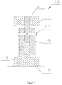
- Rotation system 10 is designed as a turbocompressor. It contains a housing 11 and a shaft 12 which is rotatable relative to the housing 11. A bearing disk 13 which is flat in this exemplary embodiment is fastened to the shaft 12. A Bearing assembly 14 supports the bearing plate 13 relative to the housing 11 by means of an axial gas bearing.
- the bearing assembly 14 has, from the inside to the outside, a radially inner region 15 which supports the bearing disk 13, a radially central region 16 and a radially outer region 17 held by the housing 11. More precisely, it contains a spacer 21 with an inner section 22 and an outer section 23. The outer section 23 of the spacer 21 forms the radially outer region 17 of the bearing assembly 14, which is held on the housing 11. The inner section 22 of the spacer disk 21 forms a radially central region 16 of the bearing assembly 14.
- the inner section 22 of the spacer disk 21 extends between two axial bearing disks 19, which form axial bearing elements 19.
- the bearing disk 13 is mounted between the axial bearing disks 19, wherein air gaps (not shown here) formed between the axial bearing disks 19 and the bearing disk 13 ensure axial gas storage.
- two clamping blocks 26 are fastened with the aid of clamping screws 27, which extend in opposite axial directions from the inner portion 22 of the spacer 21 and only one of which can be seen here.
- the clamping screws 27 penetrate each of the two clamping blocks 26 and the spacer 21, and their screw heads are received in blind holes in the clamping block 26 shown on the right.
- the clamping blocks 26 each have a holding element in the radially inner region, which is designed as a clamping ring 20.
- the clamping rings 20 clamp the axial bearing disks 19 in the axial direction against the inner section 22 of the spacer disk 21, so that each of the two axial bearing disks 19 in the axial direction between the inner section 22 of the spacer disk 21 and one of the two clamping rings 20 are trapped.
- the clamping block 26 and the axial bearing disks 19 together form a radially inner region 15 of the bearing assembly 14.
- the inner section 22 of the spacer disk 21 (that is to say the radially central region 16 of the bearing assembly 14) contains a plurality of openings 18 penetrating it in the axial direction.
- the openings 18 form material weaknesses which ensure that the radially central region 16 of the bearing assembly 14 is designed to be more elastic than the radially inner region 15 (ie as the clamping blocks 26 and the axial bearing disks 19).
- the part of the bearing assembly 14 which supports the bearing disk 13 is rather rigid overall, so that the axial bearing disks 19 remain comparatively parallel to one another even when the housing 11 is warped.
- the radially central region 16 Due to its relatively more elastic design, the radially central region 16 as a whole permits a certain elasticity of the radially inner region 15 with respect to the warping housing 11. Alternatively or in addition to the openings 18, depressions can also be provided, which can also form material weakenings with the effects mentioned. Because of the openings 18 mentioned, the radially central region 16 is also more elastic than the radially outer region 17.
- the spacer 21 has a modulus of elasticity of preferably 60,000 MPa to 220,000 MPa.
- the axial bearing disks 19 preferably have an elastic modulus of 200,000 MPa to 650,000 MPa.
- the clamping rings 20 have a preferred elastic modulus of 60,000 MPa to 220,000 MPa.
- This rotation system 10 ensures a high degree of parallelism between the bearing disk 13 and the axial bearing disks 19 even at high rotation speeds and temperatures.
- the temperature distribution can be influenced in a targeted manner with the aid of the cooling channels 24.
- the clamping blocks 26 are structurally separated from the spacer disk 21, so that the components can each be simpler in shape and the production is therefore generally cheaper.
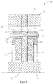
- each of the two clamping blocks 26 is clamped with the spacer 21 in the axial direction with respective clamping screws 27.
- the screw heads of the clamping screws 27 are not received in blind holes here.
- the axial bearing washers 19 are integrally formed with the clamping block.
- only one of the two axial bearing disks 19 can also be formed in one piece with a clamping block.
- the rotation system 10 according to Figure 4 differs from that in Figure 2 shown in that the inner portion 22 of the spacer 21 is penetrated by a plurality of openings 18 extending in the axial direction.
- the material weakening is not realized by an opening that completely penetrates the spacer disk 21, but by axial recesses 18 on both sides, which represent depressions 18 formed in the axial direction.
- the depressions 18 can also be arranged only on one side and / or asymmetrically.
- the material weakening 18 is formed by a bimetal or a mixture of two or more materials, in particular two or more metals, in the inner section 22 of the spacer disk 21.
- the stiffness of the spacer 21 can also be adjusted in this way.
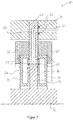
- the axial bearing disks 19 each contain a cooling channel 24 which extends in the circumferential direction and which are connected to an axial cooling channel 30 of the housing 11 via radial cooling channels 29 of the spacer disk 21.
- a cooling medium such as water
- O-rings 31 are provided, which serve for an elastic seal.
- Figure 8 shows a further embodiment in which the bearing disk 13 has a cooling channel 24 which extends in the circumferential direction and which can be supplied with a cooling medium by the shaft 12 (not shown).
- the spacer 21 can also have a cooling channel 24, for example, running in the circumferential direction - both radially inside and radially outside the clamping screws 27.
- the cooling channels 24 running radially inside the clamping screws 27 are enclosed by two parts of the spacer 21, which are connected via O-rings 31 in the axial direction.
- the two cooling channels 24 are in accordance with the sectional view Figure 9 not recognizable radial cooling channels connected.
- clamping blocks 26 are provided radially outside of the clamping screws 27 with cooling channels 24 running in the circumferential direction.
- FIG 11 it is the housing 11 which is provided, for example, with cooling channels 24 running in the circumferential direction. These cooling channels 24 are arranged on both sides of the spacer 21 in the axial direction and are closed in the radial direction on the outside by covers 28 which are sealingly fitted with O-rings 31.
- the cooling channels 24 can alternatively also be introduced directly into the housing 11 without a cover, for example by laser sintering or by laser welding.
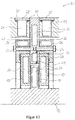
- the exemplary embodiment shown contains cooling channels 24 which run in the circumferential direction and which are arranged on both sides of the spacer disk 21 and are formed between the clamping blocks 26 and the housing 11. O-rings 31 are provided for elastic sealing between terminal blocks 26 and housing 11.
- Circumferential cooling fins 32 are formed on the radial outside of the clamping blocks 26 and extend into the cooling channels 24.
- the cooling fins 32 enlarge the surface in the cooling channels 24 and thus contribute to better heat transfer and better cooling of the axial bearing.
Landscapes
- Engineering & Computer Science (AREA)
- General Engineering & Computer Science (AREA)
- Mechanical Engineering (AREA)
- Support Of The Bearing (AREA)
- Mounting Of Bearings Or Others (AREA)
Description
- Die vorliegende Erfindung betrifft ein Rotationssystem mit mindestens einer axialen Gaslagerung.
- Rotationssysteme mit axialer Gaslagerung enthalten ein Gehäuse, eine relativ zum Gehäuse rotierbare Welle, mindestens eine an der Welle befestige Lagerscheibe und mindestens eine Lagerbaugruppe, welche die Lagerscheibe relativ zum Gehäuse durch eine axiale Gaslagerung lagert. Die Lagerbaugruppe enthält mindestens ein Axiallagerelement, welches in vielen Bauformen durch zwei Axiallagerscheiben gebildet ist, zwischen denen die Lagerscheibe gelagert ist. Zwischen der Lagerscheibe und den Axiallagerscheiben ist ein Luftspalt gebildet, der für die Gaslagerung sorgt.
- Die
DE 10 2007 062 496 A1 , die die Merkmale des Oberbegriffs des Anspruchs 1 zeigt, offenbart unter anderem Lageranordnungen, die in Verbindung mit Gasturbinentriebwerken verwendet werden. Die Lageranordnung enthält ein Paar Lamellendrucklager und ein Paar Federeinrichtungen, die im Wesentlichen koaxial an dem Paar Lamellendrucklagern angeordnet sind. Auf diese Weise wird das Lager in axialer Richtung gefedert. Die hier vorhandenen Luftspalte sind jedoch abhängig vom Gasdruck, was nachteilig ist. Weiterhin enthalten diese Lageranordnungen jeweils eine Vielzahl von unabhängigen Bauteilen, die allesamt Toleranzen unterliegen, die sich aufaddieren. - In der
DE 6907334 U ist eine elektrische Kleinmaschine mit einer umlaufenden Welle offenbart, die zumindest eine in axialer Richtung elastische Zwischenscheibe trägt. - Bei Gaslagerungen ist es entscheidend, dass die Dimensionen des genannten Luftspaltes möglichst konstant bleiben. Ein zu breiter Luftspalt würde nämlich lokal den Gasdruck reduzieren, so dass die Lagerung instabil wäre. Ein zu enger Luftspalt kann dazu führen, dass die Lagerflächen in Kontakt geraten. Insbesondere bei hohen Rotationsgeschwindigkeiten kann dies zur Zerstörung des gesamten Rotationssystems führen. Allerdings sind viele Rotationssysteme oftmals hohen Temperaturen und/oder hohen Temperaturunterschieden und/oder weiteren insbesondere variablen Betriebseinflüssen, wie beispielsweise variablen Gasdrücken oder Fliehkräften, ausgesetzt. Dies kann zu einem erheblichen Verzug von einzelnen Teilen des Rotationssystems führen. Beispielsweise kann sich bei hohen Temperaturen das Gehäuse verformen, was sich über die Lagerung auf die Lagerflächen der Axiallagerelemente überträgt. So können etwa die der Lagerscheibe zugewandten Lagerflächen zweier Axiallagerscheiben ihre Ebenheit oder Parallelität verlieren. Insgesamt kann ein sicherer Betrieb des Rotationssystems dann nicht mehr gewährleistet werden.
- Es ist eine Aufgabe der vorliegenden Erfindung, ein verbessertes Rotationssystem bereitzustellen, welches den genannten Anforderungen selbst bei hohen Rotationsgeschwindigkeiten und/oder hohen Temperaturen und/oder hohen Temperaturunterschieden und/oder weiteren insbesondere variablen Betriebseinflüssen, wie beispielsweise variablen Gasdrücken oder Fliehkräften, möglichst gerecht wird. Der zwischen Lagerbaugruppe und Lagerscheibe gebildete Luftspalt soll also selbst unter diesen Bedingungen möglichst konstant, also möglichst unabhängig von diesen Bedingungen, bleiben. Insbesondere sollen in einzelnen Ausführungsbeispiele die Lagerflächen der Axiallagerscheiben möglichst parallel zueinander bleiben.
- Diese und weitere Aufgaben werden durch das erfindungsgemässe Rotationssystem gelöst. Es enthält ein Gehäuse, eine relativ zum Gehäuse rotierbare Welle, mindestens eine an der Welle befestigte beispielsweise ebene Lagerscheibe sowie mindestens eine Lagerbaugruppe, welche die Lagerscheibe relativ zum Gehäuse durch eine axiale Gaslagerung lagert. Zwischen der Lagerbaugruppe, insbesondere deren unten noch beschriebenen Axiallagerscheiben, und der Lagerscheibe ist also ein Luftspalt gebildet. Bei der axialen Gaslagerung kann es sich um eine aerodynamische Gaslagerung, eine aerostatische Gaslagerung, eine Kippsegment-Gaslagerung (englisch: "tilting pad gas bearing") oder eine Folienlagerung handeln. Die Lagerscheibe kann, wie oben erwähnt, eben ausgebildet sein; alternativ kann sie aber auch beispielsweise konisch sein oder eine frei Geometrie aufweisen, sofern gegenüberliegende Lagerflächen einen definierten Luftspalt erlauben.
- Erfindungsgemäss weist die Lagerbaugruppe von innen nach aussen eine die Lagerscheibe lagernden radial inneren Bereich, einen radial mittleren Bereich und einen vom Gehäuse gehaltenen radial äusseren Bereich auf. Dabei enthält der radial innere Bereich mindestens ein Axiallagerelement und mindestens ein Halteelement, wobei die Lagerscheibe mittels des Axiallagerelementes gelagert ist und das Halteelement das Axiallagerelement in axialer Richtung hält.
- Durch diese erfindungsgemässe Ausbildung kann der zwischen Lagerbaugruppe und Lagerscheibe gebildete Luftspalt selbst bei hohen Rotationsgeschwindigkeiten und/oder hohen Temperaturen und/oder hohen Temperaturunterschieden und/oder weiteren insbesondere variablen Betriebseinflüssen, wie beispielsweise variablen Gasdrücken oder Fliehkräften, sehr konstant bleiben, also praktisch unabhängig von diesen Betriebseinflüssen. Denn insbesondere können entstehende Gehäuseverformungen abhängig von Betriebseinflüssen so minimiert werden, dass sich der gewünschte Luftspalt maximal in einem sehr geringen zulässigen Bereich verformt. Das Rotationssystem kann also auch unter diesen Bedingungen betrieben werden, ohne dass das Risiko einer übermässigen Verformung des Luftspaltes entsteht.
- In einigen Ausführungsbeispielen kann der radial mittlere Bereich der Lagerbaugruppe elastischer ausgebildet sein als ihr radial innerer Bereich. Hierdurch kann der Teil der Lagerbaugruppe, der die Lagerscheibe lagert, insgesamt eher starr ausgebildet sein, so dass beispielsweise die Axiallagerscheiben der Lagerbaugruppe auch bei einem Verzug des Gehäuses vergleichsweise parallel zueinander bleiben. Durch seine relativ elastischere Ausbildung erlaubt der radial mittlere Bereich insgesamt eine gewisse Elastizität des radial inneren Bereichs gegenüber dem sich verziehenden Gehäuse. Der radial mittlere Bereich kann insbesondere aufgrund zumindest einer Materialschwächung des radial mittleren Bereiches elastischer ausgebildet sein als der radial innere Bereich.
- Ferner kann der radial mittlere Bereich der Lagerbaugruppe elastischer ausgebildet sein als ihr radial äusserer Bereich. Auf diese Weise kann die Lagerbaugruppe fest und/oder genau definiert am Gehäuse angebunden werden. Der radial mittlere Bereich kann insbesondere aufgrund zumindest einer Materialschwächung des radial mittleren Bereiches elastischer ausgebildet sein als der radial äussere Bereich.
- Eine solche Materialschwächung und eine elastische Ausbildung des mittleren Bereichs tragen weiter dazu bei, dass der zwischen Lagerbaugruppe und Lagerscheibe gebildete Luftspalt selbst bei hohen Rotationsgeschwindigkeiten und/oder hohen Temperaturen und/oder hohen Temperaturunterschieden und/oder weiteren insbesondere variablen Betriebseinflüssen, wie beispielsweise variablen Gasdrücken oder Fliehkräften, sehr konstant bleibt und folglich das Rotationssystem auch unter diesen Bedingungen betrieben werden kann, ohne dass das Risiko einer übermässigen Verformung des Luftspaltes entsteht.
- Mindestens eine der Materialschwächungen kann durch eine in axialer Richtung gebildete Vertiefung oder eine die Lagerbaugruppe durchdringende Öffnung gebildet sein. Beispielsweise kann die Vertiefung der Öffnung in einer unten noch näher erläuterten Distanzscheibe gebildet sein, insbesondere in einem inneren Abschnitt einer solchen Distanzscheibe. Die Vertiefung kann beispielsweise durch eine lasergesinterte Struktur, eine Bohrung, einen Axialeinstich, eine Laserstruktur, eine Giessrippe und/oder eine gefräste Niere gebildet sein.
- Alternativ kann die Materialschwächung durch eine Kombination verschiedener Materialien und/oder eine Kombination an sich gleicher Materialien mit verschiedenen Eigenschaften erreicht werden. Verschiedene Metalle können zu einem Bimetall zusammengefügt sein. Eine Materialschwächung kann auch durch eine Mischung von zwei oder mehr Materialien, insbesondere von zwei oder mehr Metallen, erreicht werden. An sich gleiche Materialien mit verschiedenen Eigenschaften können beispielsweise durch verschiedene Arten der Herstellung und/oder Bearbeitung erhalten werden, etwa durch Weichglühen, Schäumen und/oder Lasersintern.
- In vorteilhaften Ausführungsformen hält das Halteelement das Axiallagerelement durch Klemmen, Schrauben, Löten, Schweissen, Schrumpfen, Pressen, Kleben, Kristallisationsverbindung, Pressverbindung, Kunststoffguss und/oder Lasersintern.
- Das mindestens eine Axiallagerelement kann zwei Axiallagerscheiben enthalten oder dadurch gebildet sein, zwischen denen die Lagerscheibe gelagert ist. Das mindestens eine Halteelement kann zwei Klemmringe enthalten oder dadurch gebildet sein, welche die Axiallagerscheiben in axialer Richtung einklemmen. Eine solche Einklemmung beeinflusst die Grundgeometrie der Axiallagerscheiben nicht unzulässig und/oder verhindert unzulässige Verschiebungen. Durch die Einklemmung sind kleine Verschiebungen in radialer Richtung möglich, ohne dabei den Luftspalt unzulässig zu beeinflussen.
- Bevorzugt enthält das Halteelement zwei Klemmblöcke, die in einem radial inneren Bereich jeweils einen der Klemmringe aufweisen. Zur Vereinfachung der Bauform können die Klemmblöcke jeweils einstückig ausgebildet sein.
- Bevorzugt ist der radial mittlere Bereich der Lagerbaugruppe durch einen inneren Abschnitt einer Distanzscheibe gebildet, an dem der radial innere Bereich der Lagerbaugruppe befestigt ist. Eine solche Distanzscheibe ermöglicht ein einfaches und/oder genaues Abstimmen des Luftspalts. Die Distanzscheibe kann mindestens ein Metall und/oder mindestens einen Kunststoff enthalten oder daraus bestehen.
- Insbesondere können die oben beschriebenen Klemmringe oder die die Klemmringe aufweisenden Klemmblöcke am inneren Abschnitt der Distanzscheibe befestigt sein. Bevorzugt erstrecken sich dabei die Klemmringe oder die die Klemmringe aufweisenden Klemmblöcke in entgegengesetzten axialen Richtungen vom inneren Abschnitt der Distanzscheibe weg.
- Dabei ist es besonders vorteilhaft, wenn der radial äussere Bereich der Lagerbaugruppe durch einen äusseren Abschnitt der Distanzscheibe gebildet ist, der am Gehäuse gehalten ist. In Kombination mit der Distanzscheibe und dem Gehäuse ergibt dies eine höhere Stabilität, aber insbesondere auch eine genaue Anbindung.
- Weiterhin vorteilhaft ist es, wenn sich der innere Abschnitt der Distanzscheibe bis zwischen zwei Axiallagerscheiben zum radial inneren Bereich der Lagerbaugruppe erstreckt. Mit Hilfe der oben beschriebenen Klemmringe können dann die Axiallagerscheiben in axialer Richtung gegen den inneren Abschnitt der Distanzscheibe verspannt werden, so dass jede der beiden Axiallagerscheiben in axialer Richtung zwischen dem inneren Abschnitt der Distanzscheibe und einem der Klemmblöcke eingeklemmt sind.
- Der radial mittlere Bereich, insbesondere die Distanzscheibe, weist mit Vorteil einen Elastizitätsmodul im Bereich von 1'000 MPa bis 700'000 MPa, bevorzugt von 3'000 MPa bis 400'000 MPa, besonders bevorzugt von 60'000 MPa bis 220'000 MPa auf.
- Der radial innere Bereich, insbesondere die Klemmringe, weisen mit Vorteil einen Elastizitätsmodul im Bereich von 1'000 MPa bis 700'000 MPa, bevorzugt von 3'000 MPa bis 400'000 MPa, besonders bevorzugt von 60'000 MPa bis 220'000 MPa auf.
- Der radial innere Bereich, insbesondere die Axiallagerscheiben, weisen mit Vorteil einen Elastizitätsmodul im Bereich von 10'000 MPa bis 900'000 MPa, bevorzugt von 100'000 MPa bis 700'000 MPa, besonders bevorzugt von 200'000 MPa bis 650'000 MPa auf.
- Besonders bevorzugt weist die Lagerbaugruppe mindestens einen sich in Umfangsrichtung erstreckenden Kühlkanal auf. Ein solcher Kühlkanal kann beispielsweise innerhalb der an der Welle befestigten Lagerscheibe oder ausserhalb, insbesondere radial ausserhalb, dieser Lagerscheibe gebildet sein. Mit Hilfe eines solchen Kühlkanals kann die Temperaturverteilung innerhalb des Rotationssystems eingestellt werden. Dies kann einen weiteren Beitrag dazu leisten, dass der Luftspalt eine möglichst definierte Geometrie behält. Der Kühlkanal kann beispielsweise durch eine Nut definiert sein, die in einem radial äusseren Bereich der oben genannten Klemmblöcke gebildet ist und die in axialer Richtung von der Lagerscheibe weg durch einen ringförmigen Deckel verschlossen ist. Alternativ kann der Kühlkanal in der an der Welle befestigten Lagerscheibe, in einem Axiallagerelement, insbesondere einer Axiallagerscheibe, in der Distanzscheibe oder im Gehäuse gebildet sein.
- Alternativ oder zusätzlich kann eine Kühlung beispielweise durch eine radiale Nut an den Klemmblöcken im äusseren Bereich ausgebildet sein und über Dichtungselemente, beispielsweise O-Ringe, zum Gehäuse hin abgedichtet werden.
- Der sich in Umfangsrichtung erstreckende Kühlkanal kann mit einem radialen Kühlkanal in der Lagerbaugruppe, insbesondere in der Distanzscheibe, verbunden sein. Ferner kann der radiale Kühlkanal in der Lagerbaugruppe mit einem axialen Kühlkanal im Gehäuse verbunden sein. Auf diese Weise kann die Lageranordnung besonders effektiv gekühlt werden.
- Im Kühlkanal kann mindestens eine Oberflächenvergrösserungsstruktur vorhanden sein. Darunter wird eine Struktur verstanden, die für eine Vergrösserung der den Kühlkanal begrenzenden Flächen sorgt. Auf diese Weise kann eine noch weiter verbesserte Wärmeübertragung und damit Kühlung erreicht werden. Die Oberflächenvergrösserungsstruktur kann beispielsweise eine oder mehrere Kühlrippen enthalten, die etwa kragenförmig ausgebildet sein können.
- In einigen Ausführungsbeispielen kann eine Axiallagerscheibe auch einstückig mit einem Klemmblock ausgebildet sein, was die Herstellung erleichtert und die Toleranzen reduziert.
- Bei dem Rotationssystem kann es sich um eine insbesondere elektrisch angetriebene Strömungsmaschine handeln, wie beispielsweise einen Verdichter, insbesondere einen Turboverdichter, einen Motor oder einen Generator, um eine Turbine, insbesondere einen Turbogenerator, um einen Turbolader, um ein Kupplungssystem (insbesondere eine Magnetkupplung) oder um ein Schwungrad, insbesondere einen kinetischen Speicher.
- Im Folgenden wird die Erfindung anhand eines Ausführungsbeispiels näher erläutert. Dabei zeigen, jeweils in einer seitlichen Schnittansicht,
- Figur 1:
- ein erstes erfindungsgemässes Rotationssystem;
- Figur 2:
- ein zweites erfindungsgemässes Rotationssystem mit vereinfachten Klemmblöcken;
- Figur 3:
- ein nicht erfindungsgemässes Rotationssystem mit einem einstückig mit einer Axiallagerscheibe ausgebildeten Klemmblock;
- Figur 4:
- ein drittes erfindungsgemässes Rotationssystem mit Öffnungen als Materialschwächung;
- Figur 5:
- ein viertes erfindungsgemässes Rotationssystem mit axialen Einstichen als Materialschwächungen;
- Figur 6:
- ein fünftes erfindungsgemässes Rotationssystem mit einem Bimetall als Materialschwächung;
- Figur 7:
- ein sechstes erfindungsgemässes Rotationssystem mit einem radialen und einem axialen Kühlkanal;
- Figur 8:
- ein siebtes erfindungsgemässes Rotationssystem mit einem Kühlkanal in der Lagerscheibe;
- Figur 9:
- ein achtes erfindungsgemässes Rotationssystem mit Kühlkanälen in der Distanzscheibe;
- Figur 10:
- ein neuntes erfindungsgemässes Rotationssystem mit Kühlkanälen in den Klemmblöcken;
- Figur 11:
- ein zehntes erfindungsgemässes Rotationssystem mit Kühlkanälen im Gehäuse;
- Figur 12:
- ein elftes erfindungsgemässes Rotationssystem mit mehreren Kühlkanälen;
- Figur 13:
- ein zwölftes erfindungsgemässes Rotationssystem mit mehreren Kühlkanälen.
- Das in
Figur 1 dargestellt Rotationssystem 10 ist als Turboverdichter ausgebildet. Es enthält ein Gehäuse 11 und eine relativ zum Gehäuse 11 rotierbare Welle 12. An der Welle 12 ist eine in diesem Ausführungsbeispiel ebene Lagerscheibe 13 befestigt. Eine Lagerbaugruppe 14 lagert die Lagerscheibe 13 relativ zum Gehäuse 11 durch eine axiale Gaslagerung. - Die Lagerbaugruppe 14 weist von innen nach aussen einen die Lagerscheibe 13 lagernden radialen inneren Bereich 15, einen radial mittleren Bereich 16 und einen vom Gehäuse 11 gehaltenen radialen äusseren Bereich 17 auf. Genauer enthält sie eine Distanzscheibe 21 mit einem inneren Abschnitt 22 und einem äusseren Abschnitt 23. Der äussere Abschnitt 23 der Distanzscheibe 21 bildet den radial äusseren Bereich 17 der Lagerbaugruppe 14, der am Gehäuse 11 gehalten ist. Der innere Abschnitt 22 der Distanzscheibe 21 bildet einen radial mittleren Bereich 16 der Lagerbaugruppe 14.
- Der innere Abschnitt 22 der Distanzscheibe 21 erstreckt sich bis zwischen zwei Axiallagerscheiben 19, welche Axiallagerelemente 19 bilden. Zwischen den Axiallagerscheiben 19 ist die Lagerscheibe 13 gelagert, wobei zwischen den Axiallagerscheiben 19 und der Lagerscheibe 13 gebildete, hier nicht erkennbare Luftspalte für eine axiale Gaslagerung sorgen. Am inneren Abschnitt 22 der Distanzscheibe 21 sind mit Hilfe von Spannschrauben 27 zwei Klemmblöcke 26 befestigt, die sich in entgegengesetzten axialen Richtungen vom inneren Abschnitt 22 der Distanzscheibe 21 weg erstrecken und von denen hier nur eine erkennbar ist. Die Spannschrauben 27 durchdringen jeweils beide Klemmblöcke 26 und die Distanzscheibe 21, und ihre Schraubenköpfe sind in Sackbohrungen des rechts dargestellten Klemmblocks 26 aufgenommen. Die Klemmblöcke 26 verfügen im radial inneren Bereich über je ein Halteelement, welches als Klemmring 20 ausgebildet ist. Mittels der Spannschrauben 27 verspannen die Klemmringe 20 die Axiallagerscheiben 19 in axialer Richtung gegen den inneren Abschnitt 22 der Distanzscheibe 21, so dass jede der beiden Axiallagerscheiben 19 in axialer Richtung zwischen dem inneren Abschnitt 22 der Distanzscheibe 21 und einem der beiden Klemmringe 20 eingeklemmt sind. Der Klemmblock 26 und die Axiallagerscheiben 19 bilden zusammen einen radial inneren Bereich 15 der Lagerbaugruppe 14.
- Im hier dargestellten Ausführungsbeispiel enthält der innere Abschnitt 22 der Distanzscheibe 21 (also der radial mittlere Bereich 16 der Lagerbaugruppe 14) mehrere ihn in axialer Richtung durchdringende Öffnungen 18. Auf diese Weise bilden die Öffnungen 18 Materialschwächungen, die dafür sorgen, dass der radial mittlere Bereich 16 der Lagerbaugruppe 14 elastischer ausgebildet ist als der radial innere Bereich 15 (also als die Klemmblöcke 26 und die Axiallagerscheiben 19). Hierdurch ist der Teil der Lagerbaugruppe 14, der die Lagerscheibe 13 lagert, insgesamt eher starr ausgebildet, so dass die Axiallagerscheiben 19 auch bei einem Verzug des Gehäuses 11 vergleichsweise parallel zueinander bleiben. Durch seine relativ elastischere Ausbildung erlaubt der radial mittlere Bereich 16 insgesamt eine gewisses Elastizität des radial inneren Bereichs 15 gegenüber dem sich verziehenden Gehäuse 11. Alternativ oder zusätzlich zu den Öffnungen 18 können auch Vertiefungen vorgesehen sein, welche ebenfalls Materialschwächungen mit den genannten Effekten bilden können. Aufgrund der genannten Öffnungen 18 ist der radial mittlere Bereich 16 auch elastischer ausgebildet als der radial äussere Bereich 17.
- Die Distanzscheibe 21 weist ein Elastizitätsmodul von bevorzugt 60'000 MPa bis 220'000 MPa auf. Die Axiallagerscheiben 19 verfügen bevorzugt über ein Elastizitätsmodul von 200'000 MPa bis 650'000 MPa. Die Klemmringe 20 haben einen bevorzugten Elastizitätsmodul von 60'000 MPa bis 220'000 MPa.
- Dieses erfindungsgemässe Rotationssystem 10 sorgt selbst bei hohen Rotationsgeschwindigkeiten und Temperaturen für eine hohe Parallelität zwischen der Lagerscheibe 13 und den Axiallagerscheiben 19. Der vergleichsweise starre innere Bereich 15, der durch die Klemmblöcke 26 und die Axiallagerscheiben 19 gebildet ist, gibt dabei die Parallelität vor. Zudem erfolgt aufgrund der Öffnungen 18 eine mechanische Entkopplung zwischen den Axiallagerscheiben 19 und dem Gehäuse 11. Ferner kann mit Hilfe der Kühlkanäle 24 gezielt die Temperaturverteilung beeinflusst werden. In dem hier beschriebenen Ausführungsbeispiel sind die Klemmblöcke 26 von der Distanzscheibe 21 baulich getrennt, sodass die Bauteile jeweils einfacher geformt sein können und die Herstellung damit insgesamt günstiger ist.
- Beim Rotationsystem 10 gemäss
Figur 2 ist jeder der beiden Klemmblöcke 26 mit jeweiligen Spannschrauben 27 in axialer Richtung mit der Distanzscheibe 21 verspannt. Im Gegensatz zu Figur 1 sind die Schraubenköpfe der Spannschrauben 27 hier nicht in Sackbohrungen aufgenommen. - Im Gegensatz zu
Figur 2 sind beim nicht erfindungsgemässen Rotationssystem 10 gemässFigur 3 die Axiallagerscheiben 19 einstückig mit dem Klemmblock ausgebildet. Alternativ kann auch nur eine der beiden Axiallagerscheiben 19 einstückig mit einem Klemmblock ausgebildet sein. - Das Rotationssystem 10 gemäss
Figur 4 unterscheidet sich von dem inFigur 2 dargestellten darin, dass der innere Abschnitt 22 der Distanzscheibe 21 von mehreren in axialer Richtung verlaufenden Öffnungen 18 durchdrungen ist. - Bei dem in
Figur 5 dargestellten Rotationssystem 10 ist die Materialschwächung nicht durch eine die Distanzscheibe 21 komplett durchdringende Öffnung, sondern durch beidseitige axiale Einstiche 18 realisiert, die in axialer Richtung gebildete Vertiefungen 18 darstellen. Abweichend von diesem Ausführungsbeispiel können die Vertiefungen 18 auch nur einseitig und/oder asymmetrisch angeordnet sind. - Im Ausführungsbeispiel gemäss
Figur 6 ist die Materialschwächung 18 durch ein Bimetall oder eine Mischung von zwei oder mehr Materialien, insbesondere von zwei oder mehr Metallen, im inneren Abschnitt 22 der Distanzscheibe 21 gebildet. Auch auf dieses Weise kann die Steifigkeit der Distanzscheibe 21 eingestellt werden. - In
Figur 7 enthalten die Axiallagerscheiben 19 jeweils einen sich in Umfangsrichtung erstreckenden Kühlkanal 24, der über radiale Kühlkanäle 29 der Distanzscheibe 21 mit einem axialen Kühlkanal 30 des Gehäuses 11 verbunden sind. Auf diese Weise kann ein Kühlmedium, wie beispielsweise Wasser, durch den axialen Kühlkanal 30 und die radialen Kühlkanäle 29 in die Kühlkanäle 24 eingeleitet werden. An den Verbindungsstellen zwischen den Axiallagerscheiben 19 und der Distanzscheibe 21 sowie zwischen der Distanzscheibe 21 und dem Gehäuse 11 sind O-Ringe 31 vorgesehen, die einer elastischen Abdichtung dienen. -
Figur 8 zeigt eine weitere Ausführungsform, in der die Lagerscheibe 13 einen sich in Umfangsrichtung erstreckenden Kühlkanal 24 aufweist, der durch die Welle 12 mit einem Kühlmedium versorgt werden kann (nicht eingezeichnet). - In
Figur 9 ist gezeigt, dass auch die Distanzscheibe 21 einen beispielsweise in Umfangsrichtung verlaufenden Kühlkanal 24 aufweisen kann - und zwar sowohl radial innerhalb als auch radial ausserhalb der Spannschrauben 27. Die radial innerhalb der Spannschrauben 27 verlaufenden Kühlkanäle 24 werden durch zwei Teile der Distanzscheibe 21 eingeschlossen, die über O-Ringe 31 in axialer Richtung verbunden sind. Die beiden Kühlkanäle 24 sind über in der Schnittansicht gemässFigur 9 nicht erkennbare radiale Kühlkanäle verbunden. - In
Figur 10 sind die Klemmblöcke 26 radial ausserhalb von den Spannschrauben 27 mit in Umfangsrichtung verlaufenden Kühlkanälen 24 versehen. - In
Figur 11 ist es das Gehäuse 11, das mit beispielsweise in Umfangsrichtung verlaufenden Kühlkanälen 24 versehen ist. Diese Kühlkanäle 24 sind in axialer Richtung beidseitig von der Distanzscheibe 21 angeordnet und in radialer Richtung nach aussen durch Deckel 28 abgeschlossen, die mit O-Ringen 31 dichtend aufgesetzt sind. Die Kühlkanäle 24 können alternativ auch ohne Deckel direkt in das Gehäuse 11 eingebracht werden, beispielsweise durch Lasersintern oder durch Laserschweissen. - In
Figur 12 ist eine Ausführungsform dargestellt, die sämtliche in denFiguren 7 bis 11 gezeigten Kühlkanäle 24 enthält (mit Ausnahme der beiden inFigur 7 gezeigten Kühlkanäle 29 und 30). - Das in
Figur 13 dargestellte Ausführungsbeispiel enthält in Umfangsrichtung verlaufende Kühlkanäle 24, welche beidseits der Distanzscheibe 21 angeordnet und zwischen den Klemmblöcken 26 und dem Gehäuse 11 gebildet sind. O-Ringe 31 sind zur elastischen Abdichtung zwischen Klemmblöcken 26 und Gehäuse 11 vorgesehen. - An der radialen Aussenseite der Klemmblöcke 26 sind umlaufende Kühlrippen 32 angeformt, die sich in die Kühlkanäle 24 hinein erstrecken. Die Kühlrippen 32 vergrössern die Oberfläche in den Kühlkanälen 24 und tragen somit zu einer besseren Wärmeübertragung und besseren Kühlung des Axiallagers bei.
Claims (16)
- Rotationssystem (10) mit mindestens einer axialen Gaslagerung, enthaltend:- ein Gehäuse (11),- eine relativ zum Gehäuse (11) rotierbare Welle (12),- mindestens eine an der Welle (12) befestigte Lagerscheibe (13),- mindestens eine Lagerbaugruppe (14), welche die Lagerscheibe (13) relativ zum Gehäuse (11) durch eine axiale Gaslagerung lagert,dadurch gekennzeichnet, dass
die Lagerbaugruppe (14) von innen nach aussen einen die Lagerscheibe (13) lagernden radial inneren Bereich (15), einen radial mittleren Bereich (16) und einen vom Gehäuse (11) gehaltenen radial äusseren Bereich (17) aufweist, wobei der radial innere Bereich (15) mindestens ein Axiallagerelement (19) und mindestens ein Halteelement (20) enthält, wobei die Lagerscheibe (13) mittels des Axiallagerelementes (19) gelagert ist und das Halteelement (20) das Axiallagerelement (19) in axialer Richtung hält. - Rotationssystem (10) gemäss Anspruch 1,
dadurch gekennzeichnet, dass
der radial mittlere Bereich (16) elastischer ausgebildet ist als der radial innere Bereich (15), insbesondere aufgrund zumindest einer Materialschwächung (18) des radial mittleren Bereiches (16). - Rotationssystem (10) gemäss einem der vorangehenden Ansprüche,
dadurch gekennzeichnet, dass
der radial mittlere Bereich (16) elastischer ausgebildet ist als der radial äussere Bereich (17), insbesondere aufgrund zumindest einer Materialschwächung (18) des radial mittleren Bereiches (16). - Rotationssystem (10) gemäss einem der Ansprüche 2 und 3,
dadurch gekennzeichnet, dass
mindestens eine der Materialschwächungen (18) durch eine in axialer Richtung gebildete Vertiefung (18) oder eine die Lagerbaugruppe (14) durchdringende Öffnung (18) gebildet ist. - Rotationssystem (10) gemäss einem der vorangehenden Ansprüche,
dadurch gekennzeichnet, dass
das Halteelement (20) das Axiallagerelement (19) durch Klemmen, Schrauben, Löten, Schweissen, Schrumpfen, Pressen, Kleben, Kristallisationsverbindung Pressverbindung, Kunststoffguss und/oder Lasersintern hält. - Rotationssystem (10) gemäss Anspruch 5,
dadurch gekennzeichnet, dass
das mindestens eine Axiallagerelement (19) zwei Axiallagerscheiben (19) enthält oder dadurch gebildet ist und das mindestens eine Halteelement (20) zwei Klemmringe (20) enthält oder dadurch gebildet ist, wobei die Lagerscheibe (13) zwischen den Axiallagerscheiben (19) gelagert ist und die Klemmringe (20) die Axiallagerscheiben (19) in axialer Richtung einklemmen. - Rotationssystem (10) gemäss einem der vorangehenden Ansprüche,
dadurch gekennzeichnet, dass
der radial mittlere Bereich (16) der Lagerbaugruppe (14) durch einen inneren Abschnitt (22) einer Distanzscheibe (21) gebildet ist, an dem der radial innere Bereich (15) der Lagerbaugruppe (14), insbesondere die Klemmringe (20), befestigt ist. - Rotationssystem (10) gemäss Anspruch 7,
dadurch gekennzeichnet, dass
der radial äussere Bereich (17) der Lagerbaugruppe (14) durch einen äusseren Abschnitt (23) der Distanzscheibe (21) gebildet ist, der am Gehäuse (11) gehalten ist. - Rotationssystem (10) gemäss einem der Ansprüche 7 und 8,
dadurch gekennzeichnet, dass
sich der innere Abschnitt (22) der Distanzscheibe (21) bis zwischen zwei Axiallagerscheiben (19) des radial inneren Bereichs (15) der Lagerbaugruppe (14) erstreckt, zwischen denen die Lagerscheibe (13) gelagert ist. - Rotationssystem (10) gemäss einem der vorangehenden Ansprüche,
dadurch gekennzeichnet, dass
der radial mittlere Bereich (16), insbesondere die Distanzscheibe (21), einen Elastizitätsmodul im Bereich von 1'000 MPa bis 700'000 MPa, bevorzugt von 3'000 MPa bis 400'000 MPa, besonders bevorzugt von 60'000 MPa bis 220'000 MPa aufweist. - Rotationssystem (10) gemäss einem der vorangehenden Ansprüche,
dadurch gekennzeichnet, dass
der radial innere Bereich (15), insbesondere die Klemmringe (20), einen Elastizitätsmodul im Bereich von 1'000 MPa bis 700'000 MPa, bevorzugt von 3'000 MPa bis 400'000 MPa, besonders bevorzugt von 60'000 MPa bis 220'000 MPa aufweist. - Rotationssystem (10) gemäss einem der Ansprüche 1 bis 10,
dadurch gekennzeichnet, dass
der radial innere Bereich (15), insbesondere die Axiallagerscheiben (19) und/oder die Klemmringe (20), einen Elastizitätsmodul im Bereich von 10'000 MPa bis 900'000 MPa, bevorzugt von 100'000 MPa bis 700'000 MPa, besonders bevorzugt von 200'000 MPa bis 650'000 MPa aufweist. - Rotationssystem (10) gemäss einem der vorangehenden Ansprüche,
dadurch gekennzeichnet, dass
die Lagerbaugruppe (14) mindestens einen sich in Umfangsrichtung erstreckenden Kühlkanal (24) aufweist. - Rotationssystem (10) gemäss Anspruch 13,
dadurch gekennzeichnet, dass
der sich in Umfangsrichtung erstreckende Kühlkanal (24) mit einem radialen Kühlkanal (29) in der Lagerbaugruppe (14) verbunden ist. - Rotationssystem (10) gemäss Anspruch 14,
dadurch gekennzeichnet, dass
der radiale Kühlkanal (29) in der Lagerbaugruppe (14) mit einem axialen Kühlkanal (30) im Gehäuse (11) verbunden ist. - Rotationssystem (10) gemäss einem der vorangehenden Ansprüche,
dadurch gekennzeichnet, dass
das Rotationssystem (10) eine insbesondere elektrisch angetriebene Strömungsmaschine (10) ist, wie beispielsweise ein Verdichter, insbesondere ein Turboverdichter, ein Motor oder ein Generator, eine Turbine, insbesondere ein Turbogenerator oder ein Turbolader, ein Kupplungssystem (insbesondere eine Magnetkupplung) oder ein Schwungrad, insbesondere ein kinetischer Speicher.
Applications Claiming Priority (2)
| Application Number | Priority Date | Filing Date | Title |
|---|---|---|---|
| EP16196569.4A EP3315802A1 (de) | 2016-10-31 | 2016-10-31 | Rotationssystem mit axialer gaslagerung |
| PCT/EP2017/077725 WO2018078150A1 (de) | 2016-10-31 | 2017-10-30 | Rotationssystem mit axialer gaslagerung |
Publications (2)
| Publication Number | Publication Date |
|---|---|
| EP3532740A1 EP3532740A1 (de) | 2019-09-04 |
| EP3532740B1 true EP3532740B1 (de) | 2020-08-05 |
Family
ID=57218775
Family Applications (2)
| Application Number | Title | Priority Date | Filing Date |
|---|---|---|---|
| EP16196569.4A Withdrawn EP3315802A1 (de) | 2016-10-31 | 2016-10-31 | Rotationssystem mit axialer gaslagerung |
| EP17788265.1A Active EP3532740B1 (de) | 2016-10-31 | 2017-10-30 | Rotationssystem mit axialer gaslagerung |
Family Applications Before (1)
| Application Number | Title | Priority Date | Filing Date |
|---|---|---|---|
| EP16196569.4A Withdrawn EP3315802A1 (de) | 2016-10-31 | 2016-10-31 | Rotationssystem mit axialer gaslagerung |
Country Status (5)
| Country | Link |
|---|---|
| US (1) | US11428264B2 (de) |
| EP (2) | EP3315802A1 (de) |
| CN (1) | CN110199129B (de) |
| DK (1) | DK3532740T3 (de) |
| WO (1) | WO2018078150A1 (de) |
Families Citing this family (6)
| Publication number | Priority date | Publication date | Assignee | Title |
|---|---|---|---|---|
| US11105223B2 (en) * | 2019-08-08 | 2021-08-31 | General Electric Company | Shape memory alloy reinforced casing |
| CN112160915B (zh) | 2020-09-22 | 2025-07-11 | 珠海格力电器股份有限公司 | 压缩机 |
| JP7459746B2 (ja) * | 2020-09-30 | 2024-04-02 | 株式会社豊田自動織機 | 流体機械 |
| US20220205284A1 (en) * | 2020-12-28 | 2022-06-30 | Steven Wai-Tong Cheung | Device compatible enclosure apparatus |
| CN115654027B (zh) * | 2022-10-25 | 2025-07-15 | 浙江永成机械有限公司 | 一种高稳定性铜合金滑动轴承 |
| DE102024102694A1 (de) | 2024-01-31 | 2025-07-31 | Ebm-Papst Mulfingen Gmbh & Co. Kg | Gekühltes aerodynamisches Axiallager sowie Turbokompressor mit einem solchen Axiallager |
Family Cites Families (60)
| Publication number | Priority date | Publication date | Assignee | Title |
|---|---|---|---|---|
| US3493273A (en) * | 1968-02-09 | 1970-02-03 | Babcock & Wilcox Co | Hydrostatic machine tool spindle |
| DE6907334U (de) | 1969-02-25 | 1969-11-13 | Bosch Gmbh Robert | Elektrische kleinmaschine, insbesondere kleinmotor, mit einer umlaufenden welle |
| US5137373A (en) | 1987-05-29 | 1992-08-11 | Ide Russell D | Bearings having beam mounted bearing pads and methods of making same |
| US5102237A (en) | 1976-05-29 | 1992-04-07 | Ide Russell D | Self positioning beam mounted bearing and bearing and shaft assembly including the same |
| US5112143A (en) | 1987-05-29 | 1992-05-12 | Ide Russell D | Beam mounted bearing pad and methods of making same |
| US5054938A (en) | 1987-05-29 | 1991-10-08 | Ide Russell D | Hydrodynamic bearings having beam mounted bearing pads and sealed bearing assemblies including the same |
| JPS5912419B2 (ja) * | 1976-12-16 | 1984-03-23 | 株式会社東芝 | テ−ブル装置 |
| US4099799A (en) | 1977-04-28 | 1978-07-11 | Nasa | Cantilever mounted resilient pad gas bearing |
| CH631523A5 (de) * | 1978-09-14 | 1982-08-13 | Bbc Brown Boveri & Cie | Kammlager. |
| JPS56141866A (en) * | 1980-04-04 | 1981-11-05 | Toyota Motor Corp | Thrust bearing of rotary atomizing electrostatic coating device |
| GB2074254B (en) * | 1980-04-18 | 1984-05-02 | Rolls Royce | Bearings |
| CH658499A5 (en) | 1982-05-26 | 1986-11-14 | Bbc Brown Boveri & Cie | Resilient supporting device for shaft bearings of high-speed rotors, in particular those of turbo machines |
| IT8353070V0 (it) | 1983-03-17 | 1983-03-17 | Riv Officine Di Villar Perosa | Gruppo trasmissione per un veicolo con motore trasversale e semiassi di uguale lunghezza con albero intermedio provvisto di supporto elastico |
| US5304006A (en) | 1989-02-08 | 1994-04-19 | Ide Russell D | Self positioning beam mounted bearing and bearing and shaft assembly including the same |
| US5284392A (en) | 1987-05-29 | 1994-02-08 | Ide Russell D | Bearings having spaced pads and methods of making the same |
| US5246295A (en) | 1991-10-30 | 1993-09-21 | Ide Russell D | Non-contacting mechanical face seal of the gap-type |
| US5603574A (en) | 1987-05-29 | 1997-02-18 | Kmc, Inc. | Fluid dampened support having variable stiffness and damping |
| US5120144A (en) | 1988-02-16 | 1992-06-09 | Lund Company, Ltd. | Paper separator |
| US5328198A (en) | 1991-04-26 | 1994-07-12 | Adams Andy B | Fluid and tension band-operated hitch adaptor |
| US5503479A (en) | 1987-05-29 | 1996-04-02 | Ide; Russell D. | Low profile thrust bearings having spaced pads and methods of making the same |
| US5425584A (en) | 1987-05-29 | 1995-06-20 | Ide; Russell D. | Fluid dampened support for rolling element bearings |
| US5564836A (en) | 1987-05-29 | 1996-10-15 | Kmc, Inc. | Multi-deflection pad hydrodynamic thrust bearings having a multimode construction |
| US5066144A (en) | 1989-02-08 | 1991-11-19 | Ide Russell D | Hydrodynamic bearings having a continuous beam mounted support surface |
| US5255984A (en) | 1987-05-29 | 1993-10-26 | Ide Russell D | Variable characteristic thrust bearing |
| US5455778A (en) | 1987-05-29 | 1995-10-03 | Ide; Russell D. | Bearing design analysis apparatus and method |
| US5125754A (en) | 1987-05-29 | 1992-06-30 | Ide Russell D | Multi-deflection pad hydrodynamic thrust and journal bearings having a modular construction |
| US5660481A (en) | 1987-05-29 | 1997-08-26 | Ide; Russell D. | Hydrodynamic bearings having beam mounted bearing pads and sealed bearing assemblies including the same |
| DE3856222T2 (de) | 1987-05-29 | 1998-12-03 | Russell D. Exeter R.I. Ide | Hydrodynamisches lager und verfahren zu dessen herstellung |
| US5620260A (en) | 1987-05-29 | 1997-04-15 | Ide; Russell D. | Variable characteristic thrust bearing |
| US5489155A (en) | 1987-05-29 | 1996-02-06 | Ide; Russell D. | Tilt pad variable geometry bearings having tilting bearing pads and methods of making same |
| US5102236A (en) | 1987-05-29 | 1992-04-07 | Ide Russell D | Hydrodynamic bearings having a continuous beam mounted support surface |
| US5393145A (en) | 1987-05-29 | 1995-02-28 | Ide; Russell D. | Pad type hydrodynamic thrust bearings having a modular construction |
| US5531522A (en) | 1987-05-29 | 1996-07-02 | Kmc, Inc. | Fluid dampened support having variable stiffness and damping |
| US5421655A (en) | 1987-05-29 | 1995-06-06 | Kmc, Inc. | Fluid dampened support having variable stiffness and damping |
| US5743654A (en) | 1987-05-29 | 1998-04-28 | Kmc, Inc. | Hydrostatic and active control movable pad bearing |
| US4940347A (en) | 1988-02-16 | 1990-07-10 | Lund Company | Paper tractor feed separator |
| US5033871A (en) | 1988-10-25 | 1991-07-23 | Ide Russell D | Extrudable multi-rigidity hydrodynamic bearing and method of making the same |
| US5372431A (en) | 1988-10-25 | 1994-12-13 | Ide; Russell D. | Hydrodynamic bearings having spaced bearing pads and methods of making same |
| IL99067A0 (en) | 1990-08-06 | 1992-07-15 | Ide Russell D | Hydrodynamic bearings |
| IE920985A1 (en) | 1991-04-15 | 1992-10-21 | Russell D Ide | Hydrodynamic Bearings Having Spaced Bearing Pads and Methods¹of Making Same |
| AU4926893A (en) | 1992-09-23 | 1994-04-12 | Russell D. Ide | Pad type hydrodynamic thrust bearings having a modular construction |
| GB2371838B (en) * | 2001-02-02 | 2004-07-21 | Federal Mogul Rpb Ltd | Thrust Bearing Arrangement |
| US7883311B2 (en) | 2006-12-20 | 2011-02-08 | General Electric Company | Bearing assembly and method of assembling the same |
| US7946118B2 (en) | 2009-04-02 | 2011-05-24 | EcoMotors International | Cooling an electrically controlled turbocharger |
| JP4856748B2 (ja) | 2009-10-22 | 2012-01-18 | 本田技研工業株式会社 | 過給機 |
| DE102009052919A1 (de) | 2009-11-12 | 2011-05-19 | Daimler Ag | Aufladeeinrichtung, Verdichterrad für eine Aufladeeinrichtung sowie Turbinenrad für eine Turbine einer Aufladeeinrichtung |
| DE102010022574A1 (de) | 2010-06-02 | 2011-12-08 | Bosch Mahle Turbo Systems Gmbh & Co. Kg | Rotorwelle mit Gleitlager |
| GB201120593D0 (en) | 2011-11-29 | 2012-01-11 | Gsi Group Ltd | Gas bearing spindles and gas bearing assemblies for gas bearing spindles |
| JP2013217426A (ja) * | 2012-04-06 | 2013-10-24 | Ihi Corp | スラスト軸受 |
| JP6017865B2 (ja) | 2012-07-06 | 2016-11-02 | 大豊工業株式会社 | ターボチャージャーのすべり軸受、及びターボチャージャーの軸受構造 |
| WO2014120302A2 (en) | 2012-10-26 | 2014-08-07 | Lawrence Livermore National Security, Llc | Gas bearing compensating for radiation-induced and thermal expansion |
| CN105121806A (zh) | 2013-02-22 | 2015-12-02 | 艾克莫特公司 | 配合到涡轮机轴上的电动转子 |
| JP2015038363A (ja) * | 2013-03-29 | 2015-02-26 | Abb株式会社 | 気体軸受スピンドル |
| US9121448B2 (en) | 2013-10-11 | 2015-09-01 | General Electric Company | Hermetically sealed damper assembly and methods of assembling same |
| US9664050B2 (en) | 2013-10-25 | 2017-05-30 | Ecomotors, Inc. | Bearings for a turbomachine having an electric motor |
| KR101966093B1 (ko) | 2013-12-24 | 2019-04-08 | 현대자동차 주식회사 | 전동식 터보 차저 |
| DE112015002059T5 (de) | 2014-04-30 | 2017-01-12 | Borgwarner Inc. | Umkehrbares Gleitlager mit Spiralnut zur Verwendung in Standard- und Gegenlaufturboladern |
| EP3249786A1 (de) | 2016-05-25 | 2017-11-29 | Celeroton AG | Elektromaschine und rotor für eine elektromaschine |
| DE102016212866A1 (de) | 2016-07-14 | 2018-01-18 | Bosch Mahle Turbo Systems Gmbh & Co. Kg | Gasdynamisches Luftlager |
| FR3055678B1 (fr) * | 2016-09-02 | 2020-09-18 | Danfoss Silicon Power Gmbh | Agencement de palier axial pour un arbre d'entrainement d'un compresseur centrifuge |
-
2016
- 2016-10-31 EP EP16196569.4A patent/EP3315802A1/de not_active Withdrawn
-
2017
- 2017-10-30 CN CN201780076219.1A patent/CN110199129B/zh active Active
- 2017-10-30 US US16/345,902 patent/US11428264B2/en active Active
- 2017-10-30 EP EP17788265.1A patent/EP3532740B1/de active Active
- 2017-10-30 DK DK17788265.1T patent/DK3532740T3/da active
- 2017-10-30 WO PCT/EP2017/077725 patent/WO2018078150A1/de not_active Ceased
Non-Patent Citations (1)
| Title |
|---|
| None * |
Also Published As
| Publication number | Publication date |
|---|---|
| CN110199129B (zh) | 2021-11-02 |
| WO2018078150A1 (de) | 2018-05-03 |
| DK3532740T3 (da) | 2020-11-02 |
| US20190293119A1 (en) | 2019-09-26 |
| US11428264B2 (en) | 2022-08-30 |
| EP3315802A1 (de) | 2018-05-02 |
| EP3532740A1 (de) | 2019-09-04 |
| CN110199129A (zh) | 2019-09-03 |
Similar Documents
| Publication | Publication Date | Title |
|---|---|---|
| EP3532740B1 (de) | Rotationssystem mit axialer gaslagerung | |
| DE69715147T2 (de) | Umfangsdichtung mit keramischem rotor | |
| EP2140114B1 (de) | Axiallager insbesondere für einen turbolader | |
| DE602004004195T2 (de) | Wellendichtungsvorrichtung | |
| DE60121539T2 (de) | Wellendichtungsanordnung und Gasturbine | |
| DE60319489T2 (de) | Dichtungsanordnung | |
| EP3545205B1 (de) | Rotationssystem mit radialer gaslagerung | |
| EP1391586B1 (de) | Abgasturbolader | |
| DE112013001173T5 (de) | Systeme und Verfahren zum Schutz eines Turboladeraluminiumlagergehäuses | |
| EP1391587B1 (de) | Abgasturbolader | |
| EP3091188B1 (de) | Strömungsmaschine mit einer dichtungseinrichtung | |
| DE19543764A1 (de) | Berührungsdichtung für Strömungsmaschinen | |
| DE112015000445T5 (de) | Axiallageranordnung mit verkleideten Lagerflächen | |
| EP1688589A1 (de) | Laüferwellen-Abdichteinrichtung einer Turbomaschine | |
| DE10323310A1 (de) | Bremsscheibeneinheit | |
| WO2018162306A1 (de) | Turbine mit verstellbaren leitschaufeln | |
| EP3273077A1 (de) | Wälzlager mit montageflansch | |
| WO2019214883A1 (de) | Lagereinrichtung mit einer strukturierten welle | |
| DE10230006A1 (de) | Asynchronmaschine | |
| DE102009037393A1 (de) | Strömungsmaschine | |
| WO2010072635A1 (de) | Abgasturbolader | |
| DE102019214279A1 (de) | Seitenkanalverdichter für ein Brennstoffzellensystem zur Förderung und/oder Verdichtung eines gasförmigen Mediums | |
| DE102017118204B4 (de) | Wälzlager und Drehverhinderungsmechanismus für einen Turbolader | |
| EP2561256B1 (de) | Gleitringdichtung mit rotierendem gegenring mit exakt definierter einspannung | |
| DE102008033361A1 (de) | Spindelmotor mit hydrodynamischem Lagersystem |
Legal Events
| Date | Code | Title | Description |
|---|---|---|---|
| STAA | Information on the status of an ep patent application or granted ep patent |
Free format text: STATUS: UNKNOWN |
|
| STAA | Information on the status of an ep patent application or granted ep patent |
Free format text: STATUS: THE INTERNATIONAL PUBLICATION HAS BEEN MADE |
|
| PUAI | Public reference made under article 153(3) epc to a published international application that has entered the european phase |
Free format text: ORIGINAL CODE: 0009012 |
|
| STAA | Information on the status of an ep patent application or granted ep patent |
Free format text: STATUS: REQUEST FOR EXAMINATION WAS MADE |
|
| 17P | Request for examination filed |
Effective date: 20190430 |
|
| AK | Designated contracting states |
Kind code of ref document: A1 Designated state(s): AL AT BE BG CH CY CZ DE DK EE ES FI FR GB GR HR HU IE IS IT LI LT LU LV MC MK MT NL NO PL PT RO RS SE SI SK SM TR |
|
| AX | Request for extension of the european patent |
Extension state: BA ME |
|
| RIN1 | Information on inventor provided before grant (corrected) |
Inventor name: BOLLER, ROLF Inventor name: HAGER, SIMON |
|
| DAV | Request for validation of the european patent (deleted) | ||
| DAX | Request for extension of the european patent (deleted) | ||
| GRAP | Despatch of communication of intention to grant a patent |
Free format text: ORIGINAL CODE: EPIDOSNIGR1 |
|
| STAA | Information on the status of an ep patent application or granted ep patent |
Free format text: STATUS: GRANT OF PATENT IS INTENDED |
|
| INTG | Intention to grant announced |
Effective date: 20200220 |
|
| GRAJ | Information related to disapproval of communication of intention to grant by the applicant or resumption of examination proceedings by the epo deleted |
Free format text: ORIGINAL CODE: EPIDOSDIGR1 |
|
| STAA | Information on the status of an ep patent application or granted ep patent |
Free format text: STATUS: REQUEST FOR EXAMINATION WAS MADE |
|
| GRAR | Information related to intention to grant a patent recorded |
Free format text: ORIGINAL CODE: EPIDOSNIGR71 |
|
| GRAS | Grant fee paid |
Free format text: ORIGINAL CODE: EPIDOSNIGR3 |
|
| STAA | Information on the status of an ep patent application or granted ep patent |
Free format text: STATUS: GRANT OF PATENT IS INTENDED |
|
| GRAA | (expected) grant |
Free format text: ORIGINAL CODE: 0009210 |
|
| STAA | Information on the status of an ep patent application or granted ep patent |
Free format text: STATUS: THE PATENT HAS BEEN GRANTED |
|
| INTC | Intention to grant announced (deleted) | ||
| AK | Designated contracting states |
Kind code of ref document: B1 Designated state(s): AL AT BE BG CH CY CZ DE DK EE ES FI FR GB GR HR HU IE IS IT LI LT LU LV MC MK MT NL NO PL PT RO RS SE SI SK SM TR |
|
| INTG | Intention to grant announced |
Effective date: 20200626 |
|
| REG | Reference to a national code |
Ref country code: GB Ref legal event code: FG4D Free format text: NOT ENGLISH |
|
| REG | Reference to a national code |
Ref country code: CH Ref legal event code: EP |
|
| REG | Reference to a national code |
Ref country code: AT Ref legal event code: REF Ref document number: 1299110 Country of ref document: AT Kind code of ref document: T Effective date: 20200815 |
|
| REG | Reference to a national code |
Ref country code: DE Ref legal event code: R096 Ref document number: 502017006645 Country of ref document: DE |
|
| REG | Reference to a national code |
Ref country code: IE Ref legal event code: FG4D Free format text: LANGUAGE OF EP DOCUMENT: GERMAN |
|
| REG | Reference to a national code |
Ref country code: CH Ref legal event code: NV Representative=s name: HEPP WENGER RYFFEL AG, CH |
|
| REG | Reference to a national code |
Ref country code: DK Ref legal event code: T3 Effective date: 20201026 |
|
| RAP2 | Party data changed (patent owner data changed or rights of a patent transferred) |
Owner name: FISCHER FUEL CELL COMPRESSOR AG |
|
| REG | Reference to a national code |
Ref country code: SE Ref legal event code: TRGR |
|
| REG | Reference to a national code |
Ref country code: LT Ref legal event code: MG4D |
|
| REG | Reference to a national code |
Ref country code: NL Ref legal event code: MP Effective date: 20200805 |
|
| PG25 | Lapsed in a contracting state [announced via postgrant information from national office to epo] |
Ref country code: FI Free format text: LAPSE BECAUSE OF FAILURE TO SUBMIT A TRANSLATION OF THE DESCRIPTION OR TO PAY THE FEE WITHIN THE PRESCRIBED TIME-LIMIT Effective date: 20200805 Ref country code: BG Free format text: LAPSE BECAUSE OF FAILURE TO SUBMIT A TRANSLATION OF THE DESCRIPTION OR TO PAY THE FEE WITHIN THE PRESCRIBED TIME-LIMIT Effective date: 20201105 Ref country code: HR Free format text: LAPSE BECAUSE OF FAILURE TO SUBMIT A TRANSLATION OF THE DESCRIPTION OR TO PAY THE FEE WITHIN THE PRESCRIBED TIME-LIMIT Effective date: 20200805 Ref country code: LT Free format text: LAPSE BECAUSE OF FAILURE TO SUBMIT A TRANSLATION OF THE DESCRIPTION OR TO PAY THE FEE WITHIN THE PRESCRIBED TIME-LIMIT Effective date: 20200805 Ref country code: ES Free format text: LAPSE BECAUSE OF FAILURE TO SUBMIT A TRANSLATION OF THE DESCRIPTION OR TO PAY THE FEE WITHIN THE PRESCRIBED TIME-LIMIT Effective date: 20200805 Ref country code: PT Free format text: LAPSE BECAUSE OF FAILURE TO SUBMIT A TRANSLATION OF THE DESCRIPTION OR TO PAY THE FEE WITHIN THE PRESCRIBED TIME-LIMIT Effective date: 20201207 Ref country code: GR Free format text: LAPSE BECAUSE OF FAILURE TO SUBMIT A TRANSLATION OF THE DESCRIPTION OR TO PAY THE FEE WITHIN THE PRESCRIBED TIME-LIMIT Effective date: 20201106 Ref country code: NO Free format text: LAPSE BECAUSE OF FAILURE TO SUBMIT A TRANSLATION OF THE DESCRIPTION OR TO PAY THE FEE WITHIN THE PRESCRIBED TIME-LIMIT Effective date: 20201105 |
|
| REG | Reference to a national code |
Ref country code: AT Ref legal event code: HC Ref document number: 1299110 Country of ref document: AT Kind code of ref document: T Owner name: FISCHER FUELL CELL COMPRESSOR AG, CH Effective date: 20201221 |
|
| PG25 | Lapsed in a contracting state [announced via postgrant information from national office to epo] |
Ref country code: PL Free format text: LAPSE BECAUSE OF FAILURE TO SUBMIT A TRANSLATION OF THE DESCRIPTION OR TO PAY THE FEE WITHIN THE PRESCRIBED TIME-LIMIT Effective date: 20200805 Ref country code: RS Free format text: LAPSE BECAUSE OF FAILURE TO SUBMIT A TRANSLATION OF THE DESCRIPTION OR TO PAY THE FEE WITHIN THE PRESCRIBED TIME-LIMIT Effective date: 20200805 Ref country code: NL Free format text: LAPSE BECAUSE OF FAILURE TO SUBMIT A TRANSLATION OF THE DESCRIPTION OR TO PAY THE FEE WITHIN THE PRESCRIBED TIME-LIMIT Effective date: 20200805 Ref country code: LV Free format text: LAPSE BECAUSE OF FAILURE TO SUBMIT A TRANSLATION OF THE DESCRIPTION OR TO PAY THE FEE WITHIN THE PRESCRIBED TIME-LIMIT Effective date: 20200805 Ref country code: IS Free format text: LAPSE BECAUSE OF FAILURE TO SUBMIT A TRANSLATION OF THE DESCRIPTION OR TO PAY THE FEE WITHIN THE PRESCRIBED TIME-LIMIT Effective date: 20201205 |
|
| PG25 | Lapsed in a contracting state [announced via postgrant information from national office to epo] |
Ref country code: RO Free format text: LAPSE BECAUSE OF FAILURE TO SUBMIT A TRANSLATION OF THE DESCRIPTION OR TO PAY THE FEE WITHIN THE PRESCRIBED TIME-LIMIT Effective date: 20200805 Ref country code: CZ Free format text: LAPSE BECAUSE OF FAILURE TO SUBMIT A TRANSLATION OF THE DESCRIPTION OR TO PAY THE FEE WITHIN THE PRESCRIBED TIME-LIMIT Effective date: 20200805 Ref country code: EE Free format text: LAPSE BECAUSE OF FAILURE TO SUBMIT A TRANSLATION OF THE DESCRIPTION OR TO PAY THE FEE WITHIN THE PRESCRIBED TIME-LIMIT Effective date: 20200805 Ref country code: SM Free format text: LAPSE BECAUSE OF FAILURE TO SUBMIT A TRANSLATION OF THE DESCRIPTION OR TO PAY THE FEE WITHIN THE PRESCRIBED TIME-LIMIT Effective date: 20200805 |
|
| REG | Reference to a national code |
Ref country code: DE Ref legal event code: R097 Ref document number: 502017006645 Country of ref document: DE |
|
| PG25 | Lapsed in a contracting state [announced via postgrant information from national office to epo] |
Ref country code: AL Free format text: LAPSE BECAUSE OF FAILURE TO SUBMIT A TRANSLATION OF THE DESCRIPTION OR TO PAY THE FEE WITHIN THE PRESCRIBED TIME-LIMIT Effective date: 20200805 |
|
| PLBE | No opposition filed within time limit |
Free format text: ORIGINAL CODE: 0009261 |
|
| STAA | Information on the status of an ep patent application or granted ep patent |
Free format text: STATUS: NO OPPOSITION FILED WITHIN TIME LIMIT |
|
| PG25 | Lapsed in a contracting state [announced via postgrant information from national office to epo] |
Ref country code: LU Free format text: LAPSE BECAUSE OF NON-PAYMENT OF DUE FEES Effective date: 20201030 Ref country code: SK Free format text: LAPSE BECAUSE OF FAILURE TO SUBMIT A TRANSLATION OF THE DESCRIPTION OR TO PAY THE FEE WITHIN THE PRESCRIBED TIME-LIMIT Effective date: 20200805 Ref country code: MC Free format text: LAPSE BECAUSE OF FAILURE TO SUBMIT A TRANSLATION OF THE DESCRIPTION OR TO PAY THE FEE WITHIN THE PRESCRIBED TIME-LIMIT Effective date: 20200805 |
|
| 26N | No opposition filed |
Effective date: 20210507 |
|
| REG | Reference to a national code |
Ref country code: BE Ref legal event code: MM Effective date: 20201031 |
|
| PG25 | Lapsed in a contracting state [announced via postgrant information from national office to epo] |
Ref country code: IT Free format text: LAPSE BECAUSE OF FAILURE TO SUBMIT A TRANSLATION OF THE DESCRIPTION OR TO PAY THE FEE WITHIN THE PRESCRIBED TIME-LIMIT Effective date: 20200805 |
|
| PG25 | Lapsed in a contracting state [announced via postgrant information from national office to epo] |
Ref country code: BE Free format text: LAPSE BECAUSE OF NON-PAYMENT OF DUE FEES Effective date: 20201031 Ref country code: SI Free format text: LAPSE BECAUSE OF FAILURE TO SUBMIT A TRANSLATION OF THE DESCRIPTION OR TO PAY THE FEE WITHIN THE PRESCRIBED TIME-LIMIT Effective date: 20200805 |
|
| PG25 | Lapsed in a contracting state [announced via postgrant information from national office to epo] |
Ref country code: IE Free format text: LAPSE BECAUSE OF NON-PAYMENT OF DUE FEES Effective date: 20201030 |
|
| PG25 | Lapsed in a contracting state [announced via postgrant information from national office to epo] |
Ref country code: TR Free format text: LAPSE BECAUSE OF FAILURE TO SUBMIT A TRANSLATION OF THE DESCRIPTION OR TO PAY THE FEE WITHIN THE PRESCRIBED TIME-LIMIT Effective date: 20200805 Ref country code: MT Free format text: LAPSE BECAUSE OF FAILURE TO SUBMIT A TRANSLATION OF THE DESCRIPTION OR TO PAY THE FEE WITHIN THE PRESCRIBED TIME-LIMIT Effective date: 20200805 Ref country code: CY Free format text: LAPSE BECAUSE OF FAILURE TO SUBMIT A TRANSLATION OF THE DESCRIPTION OR TO PAY THE FEE WITHIN THE PRESCRIBED TIME-LIMIT Effective date: 20200805 |
|
| PG25 | Lapsed in a contracting state [announced via postgrant information from national office to epo] |
Ref country code: MK Free format text: LAPSE BECAUSE OF FAILURE TO SUBMIT A TRANSLATION OF THE DESCRIPTION OR TO PAY THE FEE WITHIN THE PRESCRIBED TIME-LIMIT Effective date: 20200805 |
|
| PGFP | Annual fee paid to national office [announced via postgrant information from national office to epo] |
Ref country code: GB Payment date: 20250911 Year of fee payment: 9 |
|
| PGFP | Annual fee paid to national office [announced via postgrant information from national office to epo] |
Ref country code: FR Payment date: 20250908 Year of fee payment: 9 |
|
| PGFP | Annual fee paid to national office [announced via postgrant information from national office to epo] |
Ref country code: SE Payment date: 20250910 Year of fee payment: 9 |
|
| REG | Reference to a national code |
Ref country code: CH Ref legal event code: U11 Free format text: ST27 STATUS EVENT CODE: U-0-0-U10-U11 (AS PROVIDED BY THE NATIONAL OFFICE) Effective date: 20251101 |
|
| PGFP | Annual fee paid to national office [announced via postgrant information from national office to epo] |
Ref country code: DE Payment date: 20250902 Year of fee payment: 9 |
|
| PGFP | Annual fee paid to national office [announced via postgrant information from national office to epo] |
Ref country code: AT Payment date: 20250925 Year of fee payment: 9 |
|
| PGFP | Annual fee paid to national office [announced via postgrant information from national office to epo] |
Ref country code: DK Payment date: 20251014 Year of fee payment: 9 |
|
| PGFP | Annual fee paid to national office [announced via postgrant information from national office to epo] |
Ref country code: CH Payment date: 20251101 Year of fee payment: 9 |