EP3532901B1 - Fahrzeugleitsystem und verfahren, das luftdaten aus oberflächenmontierten drucksensoren zur fahrzeugausrichtungssteuerung nutzt - Google Patents
Fahrzeugleitsystem und verfahren, das luftdaten aus oberflächenmontierten drucksensoren zur fahrzeugausrichtungssteuerung nutzt Download PDFInfo
- Publication number
- EP3532901B1 EP3532901B1 EP17863516.5A EP17863516A EP3532901B1 EP 3532901 B1 EP3532901 B1 EP 3532901B1 EP 17863516 A EP17863516 A EP 17863516A EP 3532901 B1 EP3532901 B1 EP 3532901B1
- Authority
- EP
- European Patent Office
- Prior art keywords
- vehicle
- pressure
- value
- angle
- converged
- Prior art date
- Legal status (The legal status is an assumption and is not a legal conclusion. Google has not performed a legal analysis and makes no representation as to the accuracy of the status listed.)
- Active
Links
Images






Classifications
-
- G—PHYSICS
- G05—CONTROLLING; REGULATING
- G05D—SYSTEMS FOR CONTROLLING OR REGULATING NON-ELECTRIC VARIABLES
- G05D1/00—Control of position, course, altitude or attitude of land, water, air or space vehicles, e.g. using automatic pilots
- G05D1/08—Control of attitude, i.e. control of roll, pitch, or yaw
- G05D1/0808—Control of attitude, i.e. control of roll, pitch, or yaw specially adapted for aircraft
-
- B—PERFORMING OPERATIONS; TRANSPORTING
- B64—AIRCRAFT; AVIATION; COSMONAUTICS
- B64D—EQUIPMENT FOR FITTING IN OR TO AIRCRAFT; FLIGHT SUITS; PARACHUTES; ARRANGEMENT OR MOUNTING OF POWER PLANTS OR PROPULSION TRANSMISSIONS IN AIRCRAFT
- B64D43/00—Arrangements or adaptations of instruments
- B64D43/02—Arrangements or adaptations of instruments for indicating aircraft speed or stalling conditions
-
- B—PERFORMING OPERATIONS; TRANSPORTING
- B64—AIRCRAFT; AVIATION; COSMONAUTICS
- B64C—AEROPLANES; HELICOPTERS
- B64C13/00—Control systems or transmitting systems for actuating flying-control surfaces, lift-increasing flaps, air brakes, or spoilers
- B64C13/02—Initiating means
- B64C13/16—Initiating means actuated automatically, e.g. responsive to gust detectors
- B64C13/18—Initiating means actuated automatically, e.g. responsive to gust detectors using automatic pilot
-
- B—PERFORMING OPERATIONS; TRANSPORTING
- B64—AIRCRAFT; AVIATION; COSMONAUTICS
- B64C—AEROPLANES; HELICOPTERS
- B64C13/00—Control systems or transmitting systems for actuating flying-control surfaces, lift-increasing flaps, air brakes, or spoilers
- B64C13/24—Transmitting means
- B64C13/38—Transmitting means with power amplification
- B64C13/50—Transmitting means with power amplification using electrical energy
- B64C13/503—Fly-by-Wire
-
- B—PERFORMING OPERATIONS; TRANSPORTING
- B64—AIRCRAFT; AVIATION; COSMONAUTICS
- B64G—COSMONAUTICS; VEHICLES OR EQUIPMENT THEREFOR
- B64G1/00—Cosmonautic vehicles
- B64G1/22—Parts of, or equipment specially adapted for fitting in or to, cosmonautic vehicles
- B64G1/24—Guiding or controlling apparatus, e.g. for attitude control
- B64G1/244—Spacecraft control systems
-
- G—PHYSICS
- G01—MEASURING; TESTING
- G01L—MEASURING FORCE, STRESS, TORQUE, WORK, MECHANICAL POWER, MECHANICAL EFFICIENCY, OR FLUID PRESSURE
- G01L19/00—Details of, or accessories for, apparatus for measuring steady or quasi-steady pressure of a fluent medium insofar as such details or accessories are not special to particular types of pressure gauges
- G01L19/0061—Electrical connection means
- G01L19/0084—Electrical connection means to the outside of the housing
-
- G—PHYSICS
- G01—MEASURING; TESTING
- G01P—MEASURING LINEAR OR ANGULAR SPEED, ACCELERATION, DECELERATION, OR SHOCK; INDICATING PRESENCE, ABSENCE, OR DIRECTION, OF MOVEMENT
- G01P13/00—Indicating or recording presence, absence, or direction, of movement
- G01P13/02—Indicating direction only, e.g. by weather vane
- G01P13/025—Indicating direction only, e.g. by weather vane indicating air data, i.e. flight variables of an aircraft, e.g. angle of attack, side slip, shear, yaw
-
- G—PHYSICS
- G01—MEASURING; TESTING
- G01P—MEASURING LINEAR OR ANGULAR SPEED, ACCELERATION, DECELERATION, OR SHOCK; INDICATING PRESENCE, ABSENCE, OR DIRECTION, OF MOVEMENT
- G01P5/00—Measuring speed of fluids, e.g. of air stream; Measuring speed of bodies relative to fluids, e.g. of ship, of aircraft
- G01P5/14—Measuring speed of fluids, e.g. of air stream; Measuring speed of bodies relative to fluids, e.g. of ship, of aircraft by measuring differences of pressure in the fluid
-
- B—PERFORMING OPERATIONS; TRANSPORTING
- B64—AIRCRAFT; AVIATION; COSMONAUTICS
- B64U—UNMANNED AERIAL VEHICLES [UAV]; EQUIPMENT THEREFOR
- B64U2201/00—UAVs characterised by their flight controls
-
- B—PERFORMING OPERATIONS; TRANSPORTING
- B64—AIRCRAFT; AVIATION; COSMONAUTICS
- B64U—UNMANNED AERIAL VEHICLES [UAV]; EQUIPMENT THEREFOR
- B64U2201/00—UAVs characterised by their flight controls
- B64U2201/10—UAVs characterised by their flight controls autonomous, i.e. by navigating independently from ground or air stations, e.g. by using inertial navigation systems [INS]
Definitions
- the present invention relates to a vehicle guidance system and a method for guiding a vehicle.
- US 6 253 166 B1 entitled “Stable Algorithm for Estimating Airdata from Flush Surface Pressure Measurements" by Stephen A. Whitmore et al. describes a flush air data sensing (FADS) system for estimating air data using nonintrusive surface pressure measurements from a vehicle surface.
- FDS flush air data sensing
- US 6 253 166 B1 describes transforming an airflow model by strategically taking differences from outputs of three surface pressure sensors, known as triples. This triples formulation is then used to estimate and compute air data for air surrounding a flight vehicle from the surface pressure measurements.
- Accurate air data e.g., Mach number, dynamic pressure, angle of attack, angle of sideslip, surface winds, airspeed, altitude, etc.
- US 6 253 166 B1 describes six sensors located on a nose of a flight vehicle. An angle of attack is decoupled from an angle of sideslip by using specific locations of pressure sensors aligned along the vertical meridian of the nose.
- the Triples Algorithm relies on placing pressure ports exactly on the vertical meridian.
- the object of the present invention is to provide a vehicle guidance system, a corresponding method for guiding a vehicle, and a corresponding non-transitory computer-readable storage medium having instructions for performing such a method, which allow for a real-time in-flight computation of flight parameters with greater flexibility of pressure sensor placement on a vehicle.
- this object is solved by the vehicle guidance system having the features of independent claim 1, by the method for guiding a vehicle having the features of independent claim 10, and by the non-transitory computer-readable storage medium having the features of independent claim 17. Further advantageous developments are the subject of the dependent claims.
- An exemplary embodiment of the present disclosure provides a vehicle guidance system, including: a plurality of surface-mounted pressure sensors configured to be mounted on a vehicle, each sensor being configured to detect a surface pressure distribution for a respective location of the corresponding sensor on a vehicle, respectively.
- the vehicle guidance system includes an air data estimation controller configured to be connected to each of the plurality of surface-mounted pressure sensors.
- the air data estimation controller is configured to receive an initial value for a Mach number of the vehicle; and calculate a converged value for an angle of attack of the vehicle based on first surface pressure data from a first set of the surface-mounted pressure sensors, and a converged sideslip angle value of the vehicle based on second surface pressure data from a second set of the surface- mounted pressure sensors.
- the air data estimation controller is configured to calculate a freestream dynamic pressure based on the initial value for Mach number, the calculated converged value for angle of attack, and the calculated converged sideslip angle value, and configured to calculate a freestream pressure, and calculate a converged value for Mach number based on the calculated freestream pressure and the calculated freestream dynamic pressure.
- the vehicle guidance system includes a flight control processor configured to receive the calculated converged value for Mach number and the calculated freestream pressure from the air data estimation controller, and to provide an output command for adjusting an orientation of the vehicle based on the converged value for Mach number and the freestream pressure.
- An exemplary embodiment of the present disclosure provides a method for guiding a vehicle that includes a plurality of surface-mounted pressure sensors mounted on the vehicle and an air data estimation controller connected to each of the plurality of surface-mounted pressure sensors.
- the method includes: detecting, by each surface-mounted pressure sensor, a surface pressure distribution for a respective location of the corresponding sensor on the vehicle, respectively; receiving, by the air data estimation controller, an initial value for Mach number of the vehicle; calculating, by the air data estimation controller, a freestream dynamic pressure based on the initial value for Mach number, a converged value for angle of attack of the vehicle, and a converged sideslip angle value of the vehicle; calculating a freestream pressure; calculating, by the air data estimation controller, a converged value for Mach number based on the freestream pressure and the freestream dynamic pressure; receiving, by a flight control processor, the converged value for Mach number and the freestream pressure from the air data estimation controller; and providing, by the flight control processor, an output command for adjusting an orientation of the
- An exemplary embodiment of the present disclosure provides a non-transitory computer-readable storage medium having instructions stored thereon which, when executed by at least one processor of an air data estimation controller, perform a method for guiding a vehicle, wherein the vehicle includes a plurality of surface-mounted pressure sensors mounted on the vehicle and the air data estimation controller is connected to each of the plurality of surface-mounted pressure sensors.
- the method includes: receiving a detected surface pressure distribution for a respective location of the corresponding sensor on the vehicle, respectively; receiving an initial value for Mach number of the vehicle; calculating a freestream dynamic pressure based on the initial value for Mach number, a converged value for angle of attack of the vehicle, and a converged sideslip angle value of the vehicle; calculating a freestream pressure; calculating a converged value for Mach number based on the freestream pressure and the freestream dynamic pressure; and sending, to a flight control processor, the converged value for Mach number and the freestream pressure from the air data estimation controller, so that the flight control processor can provide an output command for adjusting an orientation of the vehicle based on the converged value for Mach number and the freestream pressure.
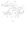
- Fig. 1 shows a vehicle guidance system for a vehicle 100 in accordance with an exemplary embodiment.
- the vehicle guidance system is a FADS system.
- the vehicle guidance system of the present disclosure allows for a real-time in-flight computation of flight parameters with greater flexibility of pressure sensor placement on a vehicle 100.
- the vehicle 100 can be, for example, an aircraft (e.g., airplane, jet, drone, etc.), spacecraft (e.g., space shuttle, etc.), missile, any other vehicle or device capable of flight, a submarine, any other vehicle or device capable of moving under water, etc.
- the vehicle guidance system includes a plurality of surface-mounted pressure sensors 122 (e.g., 122 1 , 122 2 ,..., 122 N ) configured to be mounted on a vehicle 100, each sensor 122 being configured to detect a surface pressure distribution p 1 , p 2 ,..., p N for a location of each such sensor 122 when placed on a vehicle 100.
- the vehicle guidance system provides flexibility in the placement of the surface-mounted pressure sensors 122 as they do not need to be aligned along the vertical meridian of the nose or heat shield of the vehicle as explained below.
- the exemplary embodiment of Fig. 1 shows nine surface-mounted pressure sensors 122, but the number of sensors can be any number. In a non-limiting embodiment, there are at least four surface-mounted pressure sensors 122. In a non-limiting embodiment, there are at least seven surface-mounted pressure sensors 122.
- the vehicle guidance system employs a potential flow model to obtain the effective flight angles; however, the requirements on port placement are not restrictive, allowing for configurations that are considered optimal for a FADS. Once the flight angles are known, iteration is used to capture the requisite pressures and Mach number. Finally, with the Mach number known, the true flight angles are computed.
- the potential flow model of the present disclosure can be used as either a real-time, in-flight computation or for post-flight trajectory reconstruction.
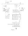
- Fig. 2 shows the geometry of the vehicle guidance system.
- the hemispherical surface can be a portion of the vehicle body 106 which can be, for example, the nose of the vehicle 100, heat shield of a re-entry capsule, or any other portion of the vehicle body.
- the x-axis, y-axis, and z-axis as discussed herein are defined as shown in Fig. 2 .
- the present disclosure is not limited to this orientation of axes, and the axes could be tilted any number of degrees in any direction.
- each surface-mounted pressure sensor 122 on the vehicle body e.g., nose of an air vehicle
- the body axis which has the x-axis pointing forward through the nose of the vehicle 100, the z-axis pointing down toward the Earth, and the y-axis pointing out the right side of the vehicle 100 to complete the right-handed triad.
- the y-axis would be in the direction of the right wing.
- the clock angle subtends from the point of symmetry on the nose to the latitude of the surface-mounted pressure sensor 122. The clock angle begins at the bottom of the vehicle 100 on the plane of symmetry and moves in a clockwise fashion to the location of the surface-mounted pressure sensor 122.
- the wind axis is used to define the angle of attack ⁇ and the sideslip angle ⁇ .
- the sideslip angle ⁇ is measured positive from the x-z plane, and is positive with a right-hand rotation about the z-axis.
- the angle of attack ⁇ is obtained in the x-z plane, and is measured positive with a right-hand rotation about the y-axis. Any point on the hemispherical surface is described by two angles, the cone angle ⁇ i and the clock angle ⁇ i .
- V ⁇ u cos ⁇ cos ⁇ v sin ⁇ w sin ⁇ cos ⁇ .
- the Triples Algorithm relies on placing pressure ports exactly on the vertical meridian.
- An iterative approach is required in order to use the triples equation when the limitation of pressure port placement is removed.
- differencing must still occur primarily parallel to the x-z plane (termed notional vertical) for determining ⁇ , and primarily parallel to the x-y plane (termed notional horizontal) for determining ⁇ .
- ⁇ 0.
- the previously converged value of ⁇ is used to start the iterations.
- Equation (22) has been found to have the desirable properties of well-spaced roots, approximately 90° apart, and well behaved near the root of interest (see Fig. 9 ). Also, the singularities have been moved to ⁇ 180°. Quadratic convergence can also be achieved for evaluating the root of interest using the Newton-Raphson method.
- Eqs. (20) and (22) provide effective flight angles, ⁇ e and ⁇ e . These angles will differ from the true flight angles, ⁇ t and ⁇ t , since the potential flow model from which the equations were derived is only approximate.
- a calibration procedure is used in order to retrieve the true flight angles from Eqs. (20) and (22).
- a database of the coefficients of pressure at each of the port locations and selected Mach numbers, angles of attack, and sideslip angles is used.
- a fourth order polynomial is required to approximate the relationship between the calibration angle ⁇ and the effective angle of attack ⁇ e at each Mach number. Once a Mach number is determined, an interpolation is performed on the coefficients of the fourth order polynomial in order to determine the ⁇ . This calibration angle is subtracted from the effective angle of attack in order to determine the true angle of attack ⁇ t .
- the stored coefficients a n,m are now functions of just Mach number and ⁇ t , and the calibration angle ⁇ is determined at the Mach numbers in the database above and below the given Mach number through the following procedure.
- the coefficients a n,m are determined at each Mach number, and with the coefficients a n,m , the coefficients b n are determined. From the coefficients b n and the effective sideslip angles, the calibration angles at each Mach number are determined.
- the calibration angle ⁇ is determined by interpolating between the two Mach numbers.
- the calibration angle is subtracted from the effective sideslip angle to obtain the true sideslip angle ⁇ t .
- FADS pressure data are used to estimate the freestream and dynamic pressure (in an exemplary embodiment, only FADS pressure data are used). This approach is useful for Mach numbers less than about Mach 2 and is shown in Fig. 4D .
- FADS pressure data and aiding e.g., GPS aiding
- FADS pressure data are used to obtain q ⁇ . Either the inertial velocity, balloon data, or an atmosphere model are used to estimate p ⁇ , or the freestream pressure can be estimated from the GPS altitude. This second approach is shown in Fig. 4E .
- the first approach shown in Fig. 4D can be used as a backup to the second approach shown in Fig. 4E . That is, if you cannot use the second approach of Fig. 4E that uses pressure data and aiding, you can use the first approach of Fig. 4D .
- the vehicle 100 is operating in a GPS-denied environment.
- the first and second approach can be used in the same vehicle guidance system. Below Mach 2, the first approach of Fig. 4D will likely provide a valid Mach number.
- the second approach of Fig. 4E can be used above Mach 1 and provides reliable values.
- the second approach of Fig. 4E has obtained reliable values at Mach 20.
- the second approach of Fig. 4E is better suited for a real-time solution, particularly at high Mach numbers (e.g., above Mach 1).
- the second approach can also be used if the first approach fails, which could be at high altitudes and supersonic to hypersonic airspeeds.
- the calibration parameter, ⁇ need not be computed.
- the database 118 of the coefficient of pressures which is obtained from Computational Fluid Dynamics (CFD) or wind tunnels with true flight angles, must be remapped to the effective flight angles.
- a linearization of the pressure model is represented by p ⁇ P x ⁇ + ⁇ P ⁇ x
- x x ⁇ x ⁇ x ⁇ + ⁇ , where x is a reference state.
- x x ⁇ .
- R is the pressure measurement covariance matrix.
- the vector y reduces to the measured pressures p. Additionally, if the errors in the pressure sensors are considered independent of each other, the covariance matrix reduces to the identity matrix multiplied by an error estimate.
- the vehicle guidance system can determine flight angles at high altitudes and high Mach numbers (e.g., above Mach 1).
- the differencing employed by this approach also provides the simplest of filters to remove noise. If it is assumed that the noise from each pressure sensor is of the same order of magnitude, than differencing should also provide more accurate predictions for pressure.
- p i q ⁇ ⁇ C p i M ⁇ , ⁇ e , ⁇ e + p ⁇
- p j q ⁇ ⁇ C p j M ⁇ , ⁇ e , ⁇ e + p ⁇ .
- the freestream pressure is eliminated in the differencing.
- an estimate of the freestream pressure p ⁇ is computed, and the Mach number is iterated until convergence.
- a new estimate for the Mach number is obtained from Eq. (44), and the iterations continue until reaching a specified level of convergence.
- the second approach can also be used in real-time if the latest balloon data or atmosphere model is loaded into the vehicle 100 prior to re-entry. If balloon data are not available, reasonable results can still be obtained by converting the GPS altitude directly into a freestream pressure p ⁇ estimate.
- the vehicle guidance system includes an air data estimation controller 102 connected to each of the plurality of surface-mounted pressure sensors 122.
- Each of the plurality of surface-mounted pressure sensors 122 are connected to a pressure measurement bus 104.
- the air data estimation controller 102 includes a preprocessor 114 that computes a calibrated angle of attack ⁇ c and a calibrated sideslip angle ⁇ c . These calibrated values are computed values that are estimates (e.g., close approximations). The calibrated values are then later converted to the true (i.e., real) angle of attack ⁇ t and the true sideslip angle ⁇ t .
- the pressure measurement bus 104 is connected to the preprocessor 114, and the pressure measurement bus 104 outputs the surface pressure distribution value associated with each of the surface-mounted pressure sensors 122 to the preprocessor 114, the air data processor 116, or other subsystems of the air data estimation controller 102.
- the air data estimation controller 102 also includes an air data postprocessor 128 that receives the Mach number M ⁇ and the converged freestream dynamic pressure q ⁇ from the air data processor 116.
- the air data postprocessor 128 computes the true angle of attack ⁇ t , the true sideslip angle ⁇ t , and other air data quantities which are outputted to the air data bus 108.
- the air data estimation controller 102 also includes a freestream pressure preprocessor 124 that computes a freestream pressure p ⁇ .
- the freestream pressure preprocessor 124 is shown in greater detail in Fig. 5 .
- the freestream pressure preprocessor 124 can receive pressure data from one or more static ports 126 located on the vehicle 100.
- Fig. 3 illustrates an overview of steps performed by the preprocessor 114 in order to determine one or more angle of attack values ⁇ and one or more sideslip angles ⁇ .
- the preprocessor 114 After the preprocessor 114 has determined one or more angle of attack values ⁇ and one or more sideslip angles ⁇ , the preprocessor 114 outputs one calibrated angle of attack ⁇ c value and one calibrated sideslip angle ⁇ c as discussed below.
- the preprocessor 114 is configured to set an initial value for angle of attack ⁇ 1 and set an initial value for sideslip angle ⁇ (see steps 300 and 302 of Fig. 3 ).
- the preprocessor 114 is configured to set the initial value for angle of attack ⁇ 1 to zero and the initial value for sideslip angle ⁇ to zero. Setting the initial value for the sideslip angle ⁇ to zero is usually sufficient since the sideslip angle is typically small, but a value of a previous trajectory calculation speeds convergence of the sideslip angle. That is, a previously determined value of the sideslip angle by the preprocessor 114 can be used as the initial value for the sideslip angle ⁇ . Also, a previously determined value of the angle of attack by the preprocessor 114 can be used as the initial value for the angle of attack ⁇ 1 .
- the preprocessor 114 is configured to determine a converged value for the angle of attack (e.g., ⁇ c that is equal to ⁇ ; see step 440 of Fig. 4B ) using the initial value for angle of attack ⁇ 1 , the initial value for sideslip angle ⁇ , and surface pressure distribution values of one or more first sets of three surface-mounted pressure sensors 122, each first set of three-surface mounted pressure sensors are located among three different geometric planes that are parallel to the ground.
- the first set of three surface-mounted pressure sensors 122 are each located in different x-y planes (i.e., three different x-y planes), where the x-axis and y-axis are defined as shown in Fig. 2 .
- the first set of three surface-mounted pressure sensors 122 are located among two different geometric planes that are parallel to the ground.
- step 304 of Fig. 3 the coefficients of the fourth order trigonometric polynomial are computed with the initial value for the sideslip angle ⁇ , and a Newton-Raphson method is used to iterate for a new value of the angle of attack ⁇ 2 .
- step 306 a check is performed to determine whether the initial value for angle of attack ⁇ 1 and the new value for the angle of attack ⁇ 2 has converged.
- step 308 if the absolute value of the difference of ⁇ 1 and ⁇ 2 is less than ⁇ (a predetermined tolerance value), then the angle of attack and sideslip angle computations are done.
- step 306 determines whether the initial value for the angle of attack ⁇ 1 is updated (step 310), and the value of the sideslip angle ⁇ is updated from the new angle of attack value (step 312). The iterations continue until the angle of attack value converges (i.e., Yes in step 306 is obtained).
- the preprocessor 114 is configured to provide (e.g., determine, calculate, etc.) a converged sideslip angle value (e.g., ⁇ c that is equal to ⁇ ; see step 474 of Fig. 4C ) based on the converged value for the angle of attack and surface pressure distribution values of one or more second sets of three surface-mounted pressure sensors 122, each second set of three-surface mounted pressure sensors are located among three different geometric planes that are perpendicular to the ground.
- the second set of three surface-mounted pressure sensors 122 are each located in different x-z planes, where the x-axis and z-axis are defined as shown in Fig. 2 .
- the second set of three surface-mounted pressure sensors 122 are located among two different geometric planes that are perpendicular to the ground.
- the first and second sets of pressure sensors 122 differ by at least one pressure sensor 122.
- the converged value for the angle of attack is an average of angle of attack values previously determined by the preprocessor 114.
- the converged sideslip angle value is an average of sideslip angle values previously determined by the preprocessor 114.
- the air data estimation controller 102 includes an air data processor 116 configured to estimate air data parameters based on the converged value for the angle of attack ⁇ c and the converged sideslip angle value ⁇ c .
- the air data processor 116 is connected to the preprocessor 114, and data can be transmitted between the air data processor 116 and the preprocessor 114.
- the data can include, for example, one or more angle of attack values and one or more values for sideslip angle.
- the air data parameters can be one or more of: Mach number, dynamic pressure, angle of attack, angle of sideslip, surface winds, airspeed, altitude, etc.
- the air data estimation controller 102 can also include the database 118 that is connected to the air data processor 116.
- the database 118 can store, for example, one or more freestream Mach number M ⁇ values, one or more angle of attack values, one or more values for sideslip angle, etc.
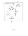
- Fig. 7 shows an exemplary table 700 that can be stored in the database 118. Fig. 7 will be discussed in greater detail later.
- the vehicle guidance system of Fig. 1 also includes a flight control processor 110 configured to provide an output for adjusting an orientation of a vehicle 100 based on the estimated air data parameters.
- the output is a control signal that is in the appropriate format to control a vehicle control system 120 which can be any device that can adjust the orientation of a vehicle 100.
- Fig. 1 shows the vehicle control system 120 connected to the flight control processor 110.
- the vehicle control system 120 can be, for example, an aileron, rudder, elevator, wing, thruster, turbine, engine, propeller, etc. That is, the vehicle control system 120 is the actual physical device or physical devices that cause the orientation of the vehicle 100 to be changed.
- the flight control processor 110 can be connected to an air data bus 108 that is connected to the air data processor 116 and one or more displays 112. All air data values that are determined by the preprocessor 114 and the air data processor 116, including the flight angles (i.e., converged angle of attack ⁇ c and converged side slip angle ⁇ c ), are sent to the air data bus 108 so they can be distributed to the one or more displays 112 and the flight control processor 110.
- the flight control processor 110 sends guidance, navigation, and control commands to the vehicle control system 120.
- the displays 112 can be operator displays, for example, vehicle instrument gauges, LCD screens, LED screens, touchscreens, or any other display that is capable of conveying air data information to a pilot or operator of a vehicle 100.
- the preprocessor 114 is configured to set the initial value for angle of attack to a value obtained from a previously converged angle of attack solution produced by the preprocessor 114 (for example, ⁇ 1 from a previous iteration; see step 300 of Fig. 3 ) or an input to the preprocessor 114 that represents a predicted trajectory of a vehicle 100.
- the vehicle guidance system can be in combination with a vehicle 100 as shown in Fig. 1 .
- the vehicle 100 includes a vehicle body 106 upon which the surface-mounted pressure sensors 122 are mounted.
- the static ports 126 can also be mounted to the vehicle body 106.
- the vehicle includes the vehicle control system 120 that is configured to receive an output of the flight control processor 110 of the vehicle guidance system for altering orientation of the vehicle 100.
- Figs. 4A-4C show the steps performed by the preprocessor 114 in order to determine one or more angle of attack values and one or more sideslip angles in greater detail than Fig. 3 .
- the calibrated or converged angle of attack ⁇ c and the calibrated or converged side slip angle ⁇ c are computed. See steps 440 and 474.
- Fig. 4D shows steps performed by the air data processor 116 to estimate air data parameters based on the converged angle of attack ⁇ c and converged side slip angle ⁇ c values determined by the preprocessor 114.
- the present disclosure includes a method for guiding a vehicle 100 that includes at least four surface-mounted pressure sensors 122 mounted on the vehicle 100 and the air data estimation controller 102 connected to each of the plurality of surface-mounted pressure sensors 122.
- the air data estimation controller 102 includes the preprocessor 114 and the air data processor 116.
- the method can include detecting, by each surface-mounted pressure sensor 122, a surface pressure distribution for a location of each such sensor 122 on the vehicle 100.
- the method can include setting, by the preprocessor 114, an initial value for angle of attack ⁇ 1 of the vehicle 100 and an initial value for sideslip angle ⁇ of the vehicle 100. See step 404 of Fig. 4A .
- the initial value for angle of attack is set to zero.
- the initial value for sideslip angle is set to zero. In an exemplary embodiment, the initial value for angle of attack is set to 20° ⁇ 5° and the initial value for sideslip angle ⁇ is set to zero. In an exemplary embodiment, the initial value for angle of attack is set to zero and the initial value for sideslip angle ⁇ is set to 30° ⁇ 5°.
- Step 404 of Fig. 4A corresponds to steps 300 and 302 in Fig. 3 . Additionally, in step 404 of Fig. 4A , an iterate value for the angle of attack ⁇ n is set. This initial iterate value will differ from the set value (e.g., initial guess) for the angle of attack as the solution proceeds.
- the method for guiding the vehicle 100 can include receiving, in the preprocessor 114, surface pressure distribution values (e.g., p i , p j , p k ) of one or more first sets of three surface-mounted pressure sensors 122, each first set of three surface-mounted pressure sensors are located among three different geometric planes that are parallel to the ground. See step 400 of Fig. 4A .
- the first set of three surface mounted sensors 122 are located among two different geometric planes that are parallel to the ground.
- three surface pressure distribution values p i , p j , p k are selected from the pressure measurement bus 104 (i.e., from among pressure measurements p 1 , p 2 ,..., p N ), with the three surface-mounted pressure sensors 122 associated with the three surface pressure distribution values each being located in different x-y planes.
- the three pressure measurements are differenced as indicated in step 402.
- a first set of parameters a i,j,k , b i,j,k , and c i,j,k are computed.
- step 408 from the first set of parameters a i,j,k , b i,j,k , and c i,j,k , a second set of parameters A i,j,k , B i,j,k , C i,j,k , D i,j,k , and E i,j,k are computed.
- the second set of parameters A i,j,k , B i,j,k , C i,j,k , D i,j,k , and E i,j,k are used with the pressure differences P ik , P ji , and P kj to obtain the coefficients of a fourth order trigonometric polynomial.
- Step 410 iterations for the angle of attack are performed.
- Step 412 is performed only if a new iteration for the angle of attack is required.
- the iterate value for the angle of attack ⁇ n is set as the initial value for the angle of attack ⁇ 1 .
- Step 400 can be re-entered if a new set of pressure differences are required without a change in sideslip angle (see the circled number 2 in Fig. 4A ), or if the sideslip angle has been updated and a whole new set of iterations are begun for the angle of attack (see the circled number 4 in Fig. 4A ).
- Fig. 4B illustrates steps that are performed by the preprocessor 114 to determine one or more angle of attack values.
- step 414 the functions f and the derivative of fare computed in order to begin the Newton-Raphson iterations in step 416.
- step 418 if it is determined that the iterates ⁇ n+1 and ⁇ n have not converged, a check is made in step 424 to ensure that the new iterate ⁇ n+1 is a number. If ⁇ n+1 is a number, in step 426 it is checked to ensure that ⁇ n+1 lies in a logical quadrant.
- step 428 the new iterate ⁇ n+1 is used to update function f and the derivative of function f until convergence of the angle of attack value.
- step 424 if the new iterate ⁇ n+1 is not a number, the process moves to another set of three pressure values that also satisfy the condition that the three surface-mounted pressure sensors 122 are located among at least two geometric planes that are parallel to the ground (step 430).
- step 418 if the iterates ⁇ n+1 and ⁇ n have converged, the converged value is saved in steps 420 and 422, and the next set of three pressure values that also satisfy the condition that the three surface-mounted pressure sensors 122 are located among at least two geometric planes that are parallel to the ground are used (step 430).
- step 432 the last converged value is used on subsequent iterations to speed convergence.
- all valid values of the angles of attack are averaged to produce the new angle of attack (step 434).
- step 476 in Fig. 4D for the first approach using pressure data or to step 490 in Fig. 4E for the second approach using pressure data and aiding.
- step 438 the initial value (e.g., a guess) for the angle of attack ⁇ 1 is updated to the value of the averaged angle of attack ⁇ , and a new value for the sideslip angle is computed (3).
- This entire process of Fig. 4B corresponds to steps 304, 306, 308, and 310 in Fig. 3 .
- a plurality of iterate values for the angle of attack e.g., ⁇ n , ⁇ n+1 , etc.
- Fig. 4C illustrates steps that are performed to determine a sideslip angle value ⁇ .
- iteration is not used to determine the sideslip angle value ⁇ .
- iteration is used to determine the sideslip angle value ⁇ .
- the method for guiding the vehicle 100 can include receiving, in the preprocessor 114, surface pressure distribution values of one or more second sets of three surface-mounted pressure sensors 122, each second set of three surface-mounted pressure sensors 122 are located among three different geometric planes that are perpendicular to the ground. That is, the three surface-mounted pressure sensors in the second set are selected so that they are located in three different x-z planes (see step 442).
- the second set of three surface-mounted pressure sensors 122 are located among two different geometric planes that are perpendicular to the ground.
- the first and second sets of pressure sensors 122 differ by at least one pressure sensor 122.
- the method for guiding the vehicle 100 can include determining, by the preprocessor 114, a converged sideslip angle value ⁇ c based on the converged value for the angle of attack ( ⁇ which is set to ⁇ 1 in step 438) and the surface pressure distribution values of the one or more second sets of three surface-mounted pressure sensors 122.
- the surface pressure distribution values of the one or more second sets of three surface-mounted pressure sensors are differenced as in step 402 of Fig. 4A .
- step 446 parameters A i,j,k and B i,j,k are determined based on the current value for the angle of attack obtained from the steps of Fig. 4A ( ⁇ 1 from step 438), and the pressure differences of step 444.
- step 448 coefficients ⁇ 0, ⁇ 1 , ⁇ 2 for a quadratic trigonometric polynomial are obtained based on the pressure differences P jk , P ji , P kj and parameters A i,j,k and B i,j,k .
- the sideslip angle value ⁇ is set to zero in step 452.
- step 454 the polynomial becomes linear and the root is explicitly given in step 456.
- two roots are determined (step 458), and the root closest to zero (step 460) is selected as the desired value (step 462 or step 464). If at any point, the sideslip angle value is not a number (step 466), this value for the sideslip angle is discarded, and the next set of three surface-mounted pressure sensors is selected (step 470).
- the sideslip angle value is a number
- the value of the sideslip angle is saved in a memory (step 468) and the next set of three surface-mounted pressure sensors that satisfy the condition that the three surface-mounted pressure sensors 122 are located among three different geometric planes that are perpendicular to the ground is selected (470). Once all the sets of three surface-mounted pressure sensors that satisfy the condition that the three surface-mounted pressure sensors 122 are located among three different geometric planes that are perpendicular to the ground have been exhausted, the sideslip angles that are determined are averaged to provide a new sideslip angle value (step 472).
- the iterations for the angle of attack begin anew with the new value of the sideslip angle ⁇ , that is set as ⁇ c in step 474 (see the circled number 4 in Fig. 4C ). Once the angle of attack has converged, the most recent sideslip angle value has converged as well.
- the steps in Fig. 4C correspond to step 312 in Fig. 3 .
- the method for guiding the vehicle 100 can include outputting the converged value for the angle of attack ⁇ c and the converged sideslip angle value ⁇ c from the preprocessor 114 to the air data processor 116.
- the method for guiding the vehicle 100 can include estimating, by the air data processor 116, air data parameters based on the converged value for the angle of attack ⁇ c and the converged sideslip angle value ⁇ c determined by the preprocessor 114.
- the initial value for angle of attack is set to a value obtained from a previously converged angle of attack solution produced by the preprocessor 114 or an input to the preprocessor 114 that represents a predicted trajectory of a vehicle 100.
- the converged value for the angle of attack is an average of angle of attack values previously determined by the preprocessor 114.
- the converged sideslip angle value is an average of sideslip angle values previously determined by the preprocessor 114.
- a plurality of iterate values for the angle of attack e.g., ⁇ n , ⁇ n+1 , etc.
- Fig. 4D illustrates steps that are performed by the air data processor 116 to determine the air data parameters.
- Fig. 4D illustrates a first approach in which FADS pressure data are used to estimate the freestream and dynamic pressure. This approach is well suited for Mach numbers less than about Mach 2.
- step 476 an initial value for the Mach number M ⁇ n is determined based on a preplanned trajectory of the vehicle 100.
- step 478 with the converged angle of attack ⁇ c (from step 440 of Fig. 4B ) and the converged sideslip angle ⁇ c computed in the preprocessor 114, an estimate of the coefficient of pressures at each of the surface-mounted pressure sensor locations C p i is made based on the Mach number, angle of attack, and sideslip table 700 stored in the database 118 and a trilinear interpolation or polynomial approximation.
- a coefficient of pressure can be directly obtained from a table entry, or can be interpolated based on the table entries.
- a new freestream pressure p ⁇ n + 1 and freestream dynamic pressure are computed q ⁇ ⁇ n + 1 .
- a new Mach number M ⁇ n + 1 is calculated.
- the computations are based on differences between two pressure ports. This differencing effectively removes noise from the pressure signals.
- step 484 if the new Mach number M ⁇ n + 1 does not equal the old Mach number M ⁇ n , the new Mach number M ⁇ n + 1 is used to obtain new coefficients of pressures (step 478), and iteration continues until there is convergence of the Mach number (step 484).
- Fig. 4E illustrates steps that are performed by the air data processor 116 to determine the air data parameters using pressure data and aiding.
- an initial value for the Mach number M ⁇ n is determined based on a preplanned trajectory of the vehicle 100.
- the preplanned trajectory is computed on the ground prior to flight of the vehicle 100, and the air data processor 116 receives an initial guess for the Mach number M ⁇ n based on the preplanned trajectory in order to start the method of Fig. 4E .
- step 492 with the converged angle of attack ⁇ c (from step 440 of Fig. 4B ) and the converged sideslip angle ⁇ c (from step 474 of Fig.
- an estimate of the coefficient of pressures at each of the surface-mounted pressure sensor locations C p i is made based on the Mach number, angle of attack, and sideslip angle table 700 stored in the database 118 and a trilinear interpolation or polynomial approximation. That is, using the Mach number M ⁇ , the converged angle of attack ⁇ c , and the converged sideslip angle ⁇ c , a coefficient of pressure can be directly obtained from a table entry, or can be interpolated based on the table entries.
- a new freestream dynamic pressure q ⁇ ⁇ n + 1 is computed.
- the freestream pressure p ⁇ is obtained from either a combination of inertial, weather balloon, and GPS data; just GPS data corrected with a local altimeter data; or from data from static pressure ports corrected with local altimeter data.
- Fig. 5 illustrates how the freestream pressure preprocessor 124 determines the freestream pressure p ⁇ value that is provided in step 498 of Fig. 4E .
- step 500 of Fig. 4E a new Mach number M ⁇ n + 1 is calculated.
- step 502 if the new Mach number M ⁇ n + 1 does not equal the old Mach number M ⁇ n , the new Mach number M ⁇ n + 1 is used to obtain new coefficients of pressures (step 492), and iteration continues until there is convergence of the Mach number (step 502).
- Fig. 5 illustrates the steps performed by the freestream pressure preprocessor 124 to determine the freestream pressure p ⁇ value (which is shown in step 498 of Fig. 4E ).
- step 600 of Fig. 5 if static pressure ports 126 are installed on the vehicle 100, the freestream pressure p ⁇ is measured directly by the static pressure ports 126.
- the static pressure ports 126 are located away from the stagnation point of the vehicle 100 (i.e., away from the nose cone where maximum heating occurs).
- the method then proceeds to step 612 in which the freestream pressure p ⁇ measured by the static pressure ports 126 is outputted from the freestream pressure preprocessor 124 and sent to the air data processor 116 (see the circled number 7 in Figs. 5 and 4E ).
- step 600 of Fig. 5 if static pressure ports 126 are not installed on the vehicle 100, GPS altitude data for the vehicle 100 is received (step 602).
- step 604 if aiding is used, the inertial velocity is obtained (e.g., from an inertial navigation system (INS)) (step 606) and temperatures and winds obtained from balloon data (step 608) are used to compute the freestream pressure p ⁇ (step 612).
- the inertial velocity and balloon data can be sent wirelessly to the vehicle 100.
- the latest balloon data or atmosphere model can be loaded into the vehicle 100 prior to re-entry or prior to departure.
- an atmosphere model (e.g., the 1976 Standard Atmosphere Model, the NASA Earth Global Reference Atmospheric Model, etc.) is used to convert the GPS altitude to an approximate freestream pressure p ⁇ .
- the freestream pressure p ⁇ is sent to the air data processor 116 and used by the air data processor 116 to compute the freestream Mach number M ⁇ and the dynamic pressure q ⁇ .
- Fig. 6 illustrates steps that can be performed by the air data postprocessor 128.
- the method proceeds to step 614 of Fig. 6 (see the circled number 8 in Figs. 4E and 6 ).
- the calibrated flight angles i.e., angle of attack ⁇ c and sideslip angle ⁇ c
- true flight angles true angle of attack ⁇ t and true sideslip angle value ⁇ t
- trilinear or polynomial interpolation step 614.
- the air data postprocessor 128 computes any other required air data quantity, such as calibrated or true airspeed, altitude, vertical velocity, etc.
- the air data postprocessor 128 outputs the true angle of attack ⁇ t , the true sideslip angle value ⁇ t , and the other air data that it has computed to the air data bus 106.
- the vehicle guidance system of Fig. 1 includes a plurality of the surface-mounted pressure sensors 122 configured to be mounted on a vehicle 100, each sensor 122 being configured to detect a surface pressure distribution for a respective location of the corresponding sensor 122 on the vehicle 100, respectively.
- the vehicle guidance system also includes an air data estimation controller 102 configured to be connected to each of the plurality of surface-mounted pressure sensors 122.
- the air data estimation controller 102 is configured to receive an initial value for a Mach number M ⁇ n of the vehicle 100.
- the air data estimation controller 102 (e.g., the preprocessor 114) is configured to calculate a converged value for an angle of attack ⁇ c of the vehicle 100 based on first surface pressure data from a first set of the surface-mounted pressure sensors 122, and a converged sideslip angle value ⁇ c of the vehicle 100 based on second surface pressure data from a second set of the surface-mounted pressure sensors 122.
- the air data estimation controller 102 (e.g., the air data processor 116) is configured to calculate a freestream dynamic pressure q ⁇ ⁇ n + 1 based at least on the initial value for Mach number M ⁇ n , the calculated converged value for angle of attack ⁇ c , and the calculated converged sideslip angle value ⁇ c .
- the air data estimation controller 102 is also configured to calculate a freestream pressure p ⁇ , and to calculate a converged value for Mach number M ⁇ based on the calculated freestream pressure p ⁇ and the calculated freestream dynamic pressure q ⁇ ⁇ n + 1 .
- the vehicle guidance system also includes a flight control processor 110 configured to receive the calculated converged value for Mach number M ⁇ and the calculated freestream pressure p ⁇ from the air data estimation controller 102, and to provide an output command for adjusting an orientation of the vehicle 100 based on the converged value for Mach number M ⁇ and the freestream pressure p ⁇ .
- the converged value for an angle of attack ⁇ c is a calibrated (i.e., estimated) value that is later converted to the true angle of attack ⁇ t .
- the converged sideslip angle value ⁇ c is a calibrated (i.e., estimated) value that is later converted to the true sideslip angle value ⁇ t .
- the number of the plurality of surface-mounted pressure sensors is at least four sensors. In an exemplary embodiment, the number of the plurality of surface-mounted pressure sensors is at least seven sensors.
- the air data estimation controller 102 is configured to set an initial value for angle of attack ⁇ 1 and set an initial value for sideslip angle ⁇ , and determine the converged value for the angle of attack ⁇ c using the initial value for angle of attack ⁇ 1 , the initial value for sideslip angle ⁇ , and the first surface data which is surface pressure distribution values of one or more third sets of three of the surface-mounted pressure sensors 122.
- Each third set of three-surface mounted pressure sensors 122 are located among three different geometric planes that are parallel to the ground.
- the air data estimation controller 102 is configured to determine the converged sideslip angle value ⁇ c based on the converged value for the angle of attack ⁇ c and the second surface pressure data which is surface pressure distribution values of one or more fourth sets of three of the surface-mounted pressure sensors 122, each fourth set of three-surface mounted pressure sensors 122 are located among three different geometric planes that are perpendicular to the ground.
- the third and fourth sets of pressure sensors 122 differ by at least one pressure sensor 122.
- the air data estimation controller 102 is configured to calculate the initial value for Mach number M ⁇ n based on a predetermined trajectory of the vehicle 100.
- the air data estimation controller 102 is configured to calculate the freestream dynamic pressure q ⁇ ⁇ n + 1 using coefficients of pressure obtained from a table 700 associating Mach number values, sideslip angle values, and angle of attack values. See step 492 of Fig. 4E .
- the air data estimation controller 102 is configured to calculate the freestream dynamic pressure q ⁇ ⁇ n + 1 also using pressure data p i , p j from two of the surface-mounted pressure sensors 122. See step 494 of Fig. 4E .
- the air data estimation controller 102 is configured to calculate the freestream pressure p ⁇ based on: a) altitude data from a global positioning system (GPS) device; b) altitude data from a global positioning system device, inertial velocity data 606 of the vehicle 100, and temperature and wind data obtained from a balloon (e.g., a weather balloon); or c) an atmosphere model and altitude data from a global positioning system device.
- the air data estimation controller 102 is configured to calculate the freestream pressure p ⁇ based on one or more of: altitude data from a global positioning system device, inertial velocity data 606 of the vehicle 100, and temperature and/or wind data obtained from a balloon.
- the air data estimation controller 102 is configured to calculate the freestream pressure p ⁇ from data from one or more of the static pressure ports 126 mounted on the vehicle 100.
- the air data estimation controller 102 includes a preprocessor 114 that determines the converged value for the angle of attack ⁇ c and the converged sideslip angle value ⁇ c , and an air data processor 116 that calculates the converged value for Mach number M ⁇ and the freestream dynamic pressure q ⁇ ⁇ n + 1 .
- the flight control processor 110 is configured to receive a converged freestream dynamic pressure q ⁇ in addition to the converged value for Mach number M ⁇ and the freestream pressure p ⁇ from the air data estimation controller 102, and to provide an output command for adjusting an orientation of a vehicle 100 based on the converged freestream dynamic pressure q ⁇ , the converged value for Mach number M ⁇ , and the freestream pressure p ⁇ .
- the air data postprocessor 128 is configured to compute a true angle of attack ⁇ t of the vehicle 100 and a true sideslip angle value ⁇ t of the vehicle 100 based on the converged value for Mach number M ⁇ , the calculated converged value for angle of attack ⁇ c , and the calculated converged sideslip angle value ⁇ c . See step 614 of Fig. 6 .
- the flight control processor 110 is configured to provide an output command for adjusting an orientation of a vehicle 100 based on the converged value for Mach number M ⁇ , the true angle of attack ⁇ t of the vehicle 100, and the true sideslip angle value ⁇ t of the vehicle 100. As seen in Fig. 1 , the output of the air data processor 128 is received by the air data bus 108.
- the air data postprocessor 128 is configured to compute one or more air data quantities (e.g., true airspeed, altitude, etc.) based on the converged value for Mach number M ⁇ and the freestream pressure p ⁇ outputted by the air data processor 116.
- the flight control processor 110 is configured to compute the one or more air data quantities based on the converged value for Mach number M ⁇ and the freestream pressure p ⁇ .
- a vehicle 100 includes the vehicle guidance system of the present disclosure, and a vehicle body 106 (e.g., nose cone, fuselage, etc.) upon which the surface-mounted pressure sensors 122 are mounted.
- the vehicle 100 also includes a vehicle control system 120 configured to receive an output of the flight control processor 110 of the vehicle guidance system for altering orientation of the vehicle 100.
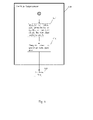
- Fig. 8 illustrates an exemplary method for guiding a vehicle 100 that includes a plurality of surface-mounted pressure sensors 122 mounted on the vehicle 100 and an air data estimation controller 102 connected to each of the plurality of surface-mounted pressure sensors.
- the method includes detecting, by each surface-mounted pressure sensor 122, a surface pressure distribution for a respective location of the corresponding sensor 122 on the vehicle 100, respectively (step S800).
- Step S802 includes receiving, by the air data estimation controller 102, an initial value for Mach number M ⁇ n of the vehicle 100.
- Step S804 includes calculating, by the air data estimation controller 102, a freestream dynamic pressure q ⁇ ⁇ n + 1 based on the initial value for Mach number M ⁇ n , a converged value for angle of attack ⁇ c of the vehicle 100, and a converged sideslip angle value ⁇ c of the vehicle 100.
- Step S806 includes calculating a freestream pressure p ⁇ .
- Step S808 includes calculating, by the air data estimation controller 102, a converged value for Mach number M ⁇ based on the freestream pressure p ⁇ and the freestream dynamic pressure q ⁇ ⁇ n + 1 .
- Step S810 includes receiving, by a flight control processor 110, the converged value for Mach number M ⁇ and the freestream pressure p ⁇ from the air data estimation controller 102.
- Step S812 includes providing, by the flight control processor 110, an output command for adjusting an orientation of the vehicle 100 based on the converged value for Mach number M ⁇ and the freestream pressure p ⁇ .
- the method includes setting, by the air data estimation controller 102, an initial value for angle of attack ⁇ 1 and setting an initial value for sideslip angle ⁇ (see steps 300 and 302 of Fig. 3 and step 404 of Fig. 4A ).
- the method includes determining, by the air data estimation controller 102, the converged value for the angle of attack ⁇ c (see step 440 of Fig. 4B ) using the initial value for angle of attack ⁇ 1 , the initial value for sideslip angle ⁇ , and surface pressure distribution values of one or more first sets of three of the surface-mounted pressure sensors 122 (see step 400 of Fig. 4A ).
- Each first set of three-surface mounted pressure sensors 122 are located among three different geometric planes that are parallel to the ground (see step 400 of Fig. 4A ).
- the method includes determining, by the air data estimation controller 102, the converged sideslip angle value ⁇ c (see step 474 of Fig. 4C ) based on the converged value for the angle of attack ⁇ c and surface pressure distribution values of one or more second sets of three of the surface-mounted pressure sensors 122 (see step 442 of Fig. 4C ).
- Each second set of three-surface mounted pressure sensors 122 are located among three different geometric planes that are perpendicular to the ground (see step 442 of Fig. 4C ).
- the first and second sets of pressure sensors 122 differ by at least one pressure sensor 122.
- the method includes calculating, by the air data estimation controller 102, the initial value for Mach number M ⁇ n based on a predetermined trajectory of the vehicle 100 (see step 490 of Fig. 4E ).
- the method includes calculating, by the air data estimation controller 102, the freestream dynamic pressure q ⁇ ⁇ n + 1 using coefficients of pressure obtained from a table (for example, the table 700 in Fig. 7 ) associating Mach number values, sideslip angle values, and angle of attack values (see step 492 of Fig. 4E ).
- the table of Fig. 7 is used to obtain the coefficients of pressure (e.g., C pi , C pj ) from the M ⁇ - ⁇ - ⁇ table via trilinear interpolation or from a polynomial approximation.
- each coefficient in each row is based on a corresponding Mach number, angle of attack value, and sideslip angle value.
- the method includes calculating, by the air data estimation controller 102, the freestream dynamic pressure q ⁇ ⁇ n + 1 using the coefficients of pressure (e.g., C pi , C pj ) and pressure data (e.g., p i , p j ) from two of the surface-mounted pressure sensors 122 (see step 494 of Fig. 4E ).
- the coefficients of pressure e.g., C pi , C pj
- pressure data e.g., p i , p j
- the method includes calculating, by the air data estimation controller 102, the freestream pressure p ⁇ (see step 612 of Fig. 5 ) based on: a) altitude data from a global positioning system device (step 602); b) altitude data from a global positioning system device (step 602), inertial velocity data of the vehicle 100 (step 606), and temperature and wind data obtained from a balloon (step 608); or c) an atmosphere model (step 610) and altitude data from a global positioning system device (step 602).
- the method includes calculating, by the air data estimation controller 102, the freestream pressure p ⁇ from data from one or more static pressure ports 126 mounted on the vehicle 100 (steps 600 and 612).
- the method includes receiving, by the flight control processor 110, a converged freestream dynamic pressure q ⁇ in addition to the converged value for Mach number M ⁇ and the freestream pressure p ⁇ from the air data estimation controller 102 (see step 506 of Fig. 4E and Fig. 6 ).
- the method also includes providing, by the flight control processor 110, an output command for adjusting an orientation of the vehicle 100 based on the converged freestream dynamic pressure q ⁇ , the converged value for Mach number M ⁇ , and the freestream pressure p ⁇ .
- the method includes computing, by the air data postprocessor 128, a true angle of attack ⁇ t of the vehicle 100 and a true sideslip angle value ⁇ t of the vehicle 100 based on the converged value for Mach number M ⁇ , the calculated converged value for angle of attack ⁇ c , and the calculated converged sideslip angle value ⁇ c (See step 614 of Fig. 6 ).
- the method also includes providing, by the flight control processor 110, an output command for adjusting an orientation of a vehicle 100 based on the converged value for Mach number M ⁇ , the true angle of attack ⁇ t of the vehicle 100, and the true sideslip angle value ⁇ t of the vehicle 100.
- the method includes receiving, by the vehicle control system 120, an output command of the flight control processor 110 of the vehicle guidance system for altering orientation of the vehicle 100.
- the method includes receiving, by the vehicle control system 120, an output command of the flight control processor 110 of the vehicle guidance system for altering orientation of the vehicle 100.
- the at least one processor device of the air data estimation controller 102 includes a preprocessor 114 that determines the converged value for the angle of attack ⁇ c and the converged sideslip angle value ⁇ c , and an air data processor 116 that calculates the converged value for Mach number M ⁇ and the freestream dynamic pressure q ⁇ ⁇ n + 1 .
- the functions of all of the processors of the air data estimation controller 102 i.e., preprocessor 114, air data processor 116, freestream pressure preprocessor 124, and air data postprocessor 128) can be performed by one or more processor devices.
- the preprocessor 114, air data processor 116, freestream pressure preprocessor 124, and air data postprocessor 128 could be one processor device.
- An exemplary embodiment is directed to a non-transitory computer-readable storage medium having instructions stored thereon which, when executed by at least one processor of an air data estimation controller 102 (e.g., one or more of preprocessor 114, air data processor 116, freestream pressure preprocessor 124, air data postprocessor 128), perform a method for guiding a vehicle 100, wherein the vehicle 100 includes a plurality of surface-mounted pressure sensors mounted on the vehicle 100 and the air data estimation controller 102 is connected to each of the plurality of surface-mounted pressure sensors.
- the method includes receiving a detected surface pressure distribution for a respective location of the corresponding sensor 122 on the vehicle 100, respectively.
- the method also includes receiving an initial value for Mach number M ⁇ n of the vehicle 100.
- the method also includes calculating a freestream dynamic pressure q ⁇ ⁇ n + 1 based on the initial value for Mach number M ⁇ n , a converged value for angle of attack ⁇ c of the vehicle 100, and a converged sideslip angle value ⁇ c of the vehicle 100.
- the method also includes calculating a freestream pressure p ⁇ . Further, the method includes calculating a converged value for Mach number M ⁇ based on the freestream pressure p ⁇ and the freestream dynamic pressure q ⁇ ⁇ n + 1 .
- the method additionally includes sending, to a flight control processor 110, the converged value for Mach number M ⁇ and the freestream pressure p ⁇ from the air data estimation controller 102, so that the flight control processor 110 can provide an output command for adjusting an orientation of the vehicle 100 based on the converged value for Mach number M ⁇ and the freestream pressure p ⁇ .
- the air data estimation controller 102 and the flight control processor 110 as discussed herein may be a single hardware processor, a plurality of hardware processors, or combinations thereof.
- Hardware processor devices may have one or more processor “cores.”
- the term “database” as discussed herein is used to generally refer to tangible media such as a memory device.
- the air data estimation controller 102 and the flight control processor 110 may be special purpose or general purpose hardware processor devices.
- the air data estimation controller 102 may be connected to a communication infrastructure, such as a bus, message queue, network, multi-core message-passing scheme, etc.
- the network may be any network suitable for performing the functions as disclosed herein and may include a wireless network (e.g., Wi-Fi), a mobile communication network, a satellite network, fiber optic, coaxial cable, infrared, radio frequency (RF), or any combination thereof. Other suitable network types and configurations will be apparent to persons having skill in the relevant art.
- the air data estimation controller 102 may also include a memory (e.g., random access memory, read-only memory, etc.). The memory may be read from and/or written to in a well-known manner. In an embodiment, the memory may be non-transitory computer readable recording media.
- Data stored in the air data estimation controller 102 may be stored on any type of suitable computer readable media, such as optical storage (e.g., a compact disc, digital versatile disc, Blu-ray disc, etc.), magnetic tape storage (e.g., a hard disk drive), or solid-state drive.
- An operating system can be stored in the database 118.
- the data may be configured in any type of suitable database configuration, such as a relational database, a structured query language (SQL) database, a distributed database, an object database, etc.
- suitable configurations and storage types will be apparent to persons having skill in the relevant art.
- the air data estimation controller 102 may also include a communications interface.
- the communications interface may be configured to allow software and data to be transferred between the air data estimation controller 102 and external devices.
- Exemplary communications interfaces may include a modem, a network interface (e.g., an Ethernet card), a communications port, a PCMCIA slot and card, etc.
- Software and data transferred via the communications interface may be in the form of signals, which may be electronic, electromagnetic, optical, or other signals as will be apparent to persons having skill in the relevant art.
- the signals may travel via a communications path, which may be configured to carry the signals and may be implemented using wire, cable, fiber optics, a cellular phone link, a radio frequency link, etc.
- Computer programs may be stored in one or more on-board memory devices. Computer programs may also be received via the communications interface. Such computer programs, when executed, may enable the air data estimation controller 102 to implement the present methods as discussed herein. In particular, the computer programs, when executed, may enable the air data estimation controller 102 to implement the methods illustrated by Figs. 3 , 4A-4E , 5 , 6 , and 8 , or similar methods, as discussed herein. Where the present disclosure is implemented using software, the software may be stored in a computer program product or non-transitory computer readable medium and loaded into the air data estimation controller 102 using a removable storage drive or communications interface.
Landscapes
- Engineering & Computer Science (AREA)
- Aviation & Aerospace Engineering (AREA)
- Physics & Mathematics (AREA)
- General Physics & Mathematics (AREA)
- Automation & Control Theory (AREA)
- Remote Sensing (AREA)
- Radar, Positioning & Navigation (AREA)
- Chemical & Material Sciences (AREA)
- Combustion & Propulsion (AREA)
- Control Of Position, Course, Altitude, Or Attitude Of Moving Bodies (AREA)
- Aerodynamic Tests, Hydrodynamic Tests, Wind Tunnels, And Water Tanks (AREA)
Claims (17)
- Fahrzeugleitsystem, umfassend:eine Vielzahl von oberflächenmontierten Drucksensoren (122), die dazu eingerichtet sind, an einem Fahrzeug (100) angebracht zu sein, wobei eine Oberflächendruckverteilung durch Oberflächendruckdaten dargestellt wird, die von zahlreichen oberflächenmontierten Drucksensoren (122) erfasst werden, die einen Satz von oberflächenmontierten Drucksensoren (122) bilden;eine Luftdaten-Schätzsteuereinheit (102), die dazu eingerichtet ist, mit jedem der zahlreichen oberflächenmontierten Drucksensoren (122) verbunden zu sein, wobei die Luftdaten-Schätzsteuereinheit (102) dazu eingerichtet ist:einen Ausgangswert für eine Machzahl des Fahrzeugs (100) zu empfangen, einen konvergierten Wert für einen Anstellwinkel (ac) des Fahrzeugs (100) auf der Grundlage eines ersten Satzes von Oberflächendruckdaten von einem ersten Satz der oberflächenmontierten Drucksensoren (122) und eines konvergierten Wertes des Schräglaufwinkels (βc) des Fahrzeugs (100) auf der Grundlage eines zweiten Satzes von Oberflächendruckdaten von einem zweiten Satz der oberflächenmontierten Drucksensoren (122) zu berechnen, einen dynamischen Freistromdruck

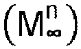 einen Freistromdruck (p∞) zu berechnen, undeinen konvergierten Wert für die Machzahl (M∞) auf der Grundlage des berechneten Freistromdrucks (p∞) und des berechneten dynamischen Freistromdrucks
 einen Flugsteuerprozessor (110), der dazu eingerichtet ist, den berechneten konvergierten Wert für die Machzahl (M∞) und den berechneten Freistromdruck (p∞) von der Luftdaten-Schätzsteuereinheit (102) zu empfangen und einen Ausgabebefehl zum Einstellen einer Ausrichtung des Fahrzeugs (100) auf der Grundlage des konvergierten Wertes für die Machzahl (M∞) und des Freistromdrucks (p∞) bereitzustellen.
 - Fahrzeugleitsystem nach Anspruch 1, bei dem die Luftdaten-Schätzsteuereinheit (102) dazu eingerichtet ist:einen Ausgangswert für den Anstellwinkel (α1) einzustellen und einen Ausgangswert für den Schräglaufwinkel (β) einzustellen und den konvergierten Wert für den Anstellwinkel (ac) unter Verwendung des Ausgangswertes für den Anstellwinkel (α1), des Ausgangswertes für den Schräglaufwinkel (β) und des ersten Satzes von Oberflächendruckdaten der drei oder mehr oberflächenmontierten Drucksensoren (122) aus dem ersten Satz der oberflächenmontierten Drucksensoren (122) zu bestimmen, wobei die oberflächenmontierten Drucksensoren (122) des ersten Satzes zwischen drei verschiedenen x-y-Ebenen angeordnet sind und die x-Achse der Längsachse des Fahrzeugs (100) und die y-Achse der Querachse des Fahrzeugs (100) entspricht, undden konvergierten Wert des Schräglaufwinkels (βc) auf der Grundlage des konvergierten Wertes für den Anstellwinkel (ac) und des zweiten Satzes von Flächendruckdaten von drei oder mehr oberflächenmontierten Drucksensoren (122) aus dem zweiten Satz der oberflächenmontierten Drucksensoren (122) zu bestimmen, wobei die oberflächenmontierten Drucksensoren (122) des zweiten Satzes in drei verschiedenen x-z-Ebenen angeordnet sind, die x-Achse der Längsachse des Fahrzeugs (100) und die z-Achse der vertikalen Achse des Fahrzeugs (100) entspricht und sich der erste sowie der zweite Satz von oberflächenmontierten Drucksensoren (122) um wenigstens einen oberflächenmontierten Drucksensor (122) unterscheiden.
- Fahrzeugleitsystem nach Anspruch 1 oder 2, bei dem die Luftdaten-Schätzsteuereinheit (102) dazu eingerichtet ist, wenigstens eines der folgenden Elemente zu berechnen:a) den Ausgangswert für die Machzahl
 b) den dynamischen Freistromdruck
 c) den dynamischen Freistromdruck
 d) den Freistromdruck (p∞) auf der Grundlage von:d1) Höhendaten aus einer GPS-Vorrichtung;d2) Höhendaten aus einer GPS-Vorrichtung, Trägheitsgeschwindigkeitsdaten (606) des Fahrzeugs (100) sowie Temperatur- und Winddaten von einem Ballon; oderd3) einem Atmosphärenmodell und Höhendaten aus einer GPS-Vorrichtung;d) den Freistromdruck (p∞) aus Daten aus einem oder zahlreichen an dem Fahrzeug (100) angebrachten statischen Druckanschlüssen (126).
 - Fahrzeugleitsystem nach Anspruch 2 oder 3, bei dem die Luftdaten-Schätzsteuereinheit (102) einen Vorprozessor (114), der den konvergierten Wert für den Anstellwinkel (ac) und den konvergierten Wert des Schräglaufwinkels (βc) bestimmt, und einen Luftdatenprozessor (116) umfasst, der den konvergierten Wert für die Machzahl (M∞) und den dynamischen Freistromdruck

- Fahrzeugleitsystem nach einem der Ansprüche 1 bis 4, bei dem der Flugsteuerprozessor (110) dazu eingerichtet ist, einen konvergierten dynamischen Freistromdruck (
q ∞) zusätzlich zu dem konvergierten Wert für die Machzahl (M∞) und den Freistromdruck (p∞) von der Luftdaten-Schätzsteuereinheit (102) zu empfangen und einen Ausgabebefehl zum Einstellen einer Ausrichtung eines Fahrzeugs (100) auf der Grundlage des konvergierten dynamischen Freistromdrucks (q ∞), des konvergierten Wertes für die Machzahl (M∞) und des Freistromdrucks (p∞) bereitzustellen. - Fahrzeugleitsystem nach einem der Ansprüche 1 bis 5,bei dem der Luftdaten-Postprozessor (128) dazu eingerichtet ist, einen wahren Anstellwinkel (αt) des Fahrzeugs (100) und einen wahren Wert des Schräglaufwinkels (βt) des Fahrzeugs (100) auf der Grundlage des konvergierten Wertes für die Machzahl (M∞), des berechneten konvergierten Wertes für den Anstellwinkel (αc) und des berechneten konvergierten Wertes des Schräglaufwinkels (βc) zu berechnen, undder Flugsteuerprozessor (110) dazu eingerichtet ist, einen Ausgabebefehl zum Einstellen einer Ausrichtung eines Fahrzeugs (100) auf der Grundlage des konvergierten Wertes für die Machzahl (M∞), des wahren Anstellwinkels (αt) des Fahrzeugs (100) und des wahren Wertes des Schräglaufwinkels (βt) des Fahrzeugs (100) bereitzustellen.
- Fahrzeugleitsystem nach einem der Ansprüche 1 bis 6, bei dem der Luftdaten-Postprozessor (128) dazu eingerichtet ist, eine oder mehrere Luftdatengrößen auf der Grundlage des konvergierten Wertes für die Machzahl (M∞) und des Freistromdrucks (p∞) zu berechnen.
- Fahrzeugleitsystem nach einem der Ansprüche 1 bis 7, bei dem die Vielzahl der oberflächenmontierten Drucksensoren (122) wenigstens vier oder sieben Sensoren beträgt.
- Fahrzeug (100) umfassend:das Fahrzeugleitsystem nach einem der Ansprüche 1 bis 8;eine Fahrzeugkarosserie (106), auf der die oberflächenmontierten Drucksensoren (122) angebracht sind; undein Fahrzeugsteuersystem (120), das dazu eingerichtet ist, eine Ausgabe des Flugsteuerprozessors (110) des Fahrzeugleitsystems zu empfangen, um die Ausrichtung des Fahrzeugs (100) zu ändern.
- Leitverfahren für ein Fahrzeug (100), das eine Vielzahl von oberflächenmontierten Drucksensoren (122), die an dem Fahrzeug (100) angebracht sind, und eine Luftdaten-Schätzsteuereinheit (102) umfasst, die mit jedem der Vielzahl von oberflächenmontierten Drucksensoren (122) verbunden ist, wobei das Verfahren umfasst:Erfassen einer Oberflächendruckverteilung durch Messen von Oberflächendruckdaten, die von zahlreichen oberflächenmontierten Drucksensoren (122) erfasst werden, die einen Satz von oberflächenmontierten Drucksensoren (122) bilden;Empfangen, durch die Luftdaten-Schätzsteuereinheit (102), eines Ausgangswertes für eine Machzahl des Fahrzeugs (100);Berechnen, durch die Luftdaten-Schätzsteuereinheit (102), eines konvergierten Wertes für einen Anstellwinkel (ac) des Fahrzeugs (100) auf der Grundlage eines ersten Satzes von Oberflächendruckdaten aus einem ersten Satz der oberflächenmontierten Drucksensoren (122) und eines konvergierten Wertes des Schräglaufwinkels (βc) des Fahrzeugs (100) auf der Grundlage eines zweiten Satzes von Oberflächendruckdaten aus einem zweiten Satz der oberflächenmontierten Drucksensoren (122),Berechnen eines dynamischen Freistromdrucks

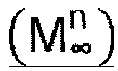 Berechnen eines Freistromdrucks (p∞);Berechnen, durch die Luftdaten-Schätzsteuereinheit (102), eines konvergierten Wertes für die Machzahl (M∞) auf der Grundlage des Freistromdrucks (p∞) und des dynamischen Freistromdrucks
 Empfangen, durch einen Flugsteuerprozessor (110), des konvergierten Wertes für die Machzahl (M∞) und des Freistromdrucks (p∞) von der Luftdaten-Schätzsteuereinheit (102); undBereitstellen, durch den Flugsteuerprozessor (110) eines Ausgabebefehls zum Einstellen einer Ausrichtung des Fahrzeugs (100) auf der Grundlage des konvergierten Wertes für die Machzahl (M∞) und des Freistromdrucks (p∞).
 - Verfahren nach Anspruch 10, umfassend:Einstellen, durch die Luftdaten-Schätzsteuereinheit (102), eines Ausgangswertes für den Anstellwinkel und eines Ausgangswertes für den Schräglaufwinkel;Bestimmen, durch die Luftdaten-Schätzsteuereinheit (102), des konvergierten Wertes für den Anstellwinkel (ac) unter Verwendung des Ausgangswertes für den Anstellwinkel (α1), des Ausgangswertes für den Schräglaufwinkel (β) und des ersten Satzes von Oberflächendruckdaten der drei oder mehr oberflächenmontierten Drucksensoren (122) aus dem ersten Satz der oberflächenmontierten Drucksensoren (122), wobei die oberflächenmontierten Drucksensoren (122) des ersten Satzes zwischen drei verschiedenen x-y-Ebenen angeordnet sind und die x-Achse der Längsachse des Fahrzeugs (100) und die y-Achse der Querachse des Fahrzeugs (100) entspricht; undBestimmen, durch die Luftdaten-Schätzsteuereinheit (102), des konvergierten Wertes des Schräglaufwinkels (βc) auf der Grundlage des konvergierten Wertes für den Anstellwinkel (αc) und des zweiten Satzes von Flächendruckdaten von drei oder mehr oberflächenmontierten Drucksensoren (122) aus dem zweiten Satz der oberflächenmontierten Drucksensoren (122), wobei die oberflächenmontierten Drucksensoren (122) des zweiten Satzes in drei verschiedenen x-z-Ebenen angeordnet sind, die x-Achse der Längsachse des Fahrzeugs (100) und die z-Achse der vertikalen Achse des Fahrzeugs (100) entspricht und sich der erste sowie der zweite Satz von oberflächenmontierten Drucksensoren (122) um wenigstens einen oberflächenmontierten Drucksensor (122) unterscheiden.
- Verfahren nach Anspruch 10 oder 11, das wenigstens einen der folgenden Schritte umfasst:a) Berechnen, durch die Luftdaten-Schätzsteuereinheit (102), des Ausgangswertes für die Machzahl
 b) Berechnen, durch die Luftdaten-Schätzsteuereinheit (102), des dynamischen Freistromdrucks
 c) Berechnen, durch die Luftdaten-Schätzsteuereinheit (102), des dynamischen Freistromdrucks
 d) Berechnen, durch die Luftdaten-Schätzsteuereinheit (102), des Freistromdrucks (p∞) auf der Grundlage von:d1) Höhendaten aus einer GPS-Vorrichtung;d2) Höhendaten aus einer GPS-Vorrichtung, Trägheitsgeschwindigkeitsdaten (606) des Fahrzeugs (100) sowie Temperatur- und Winddaten von einem Ballon; oderd3) einem Atmosphärenmodell und Höhendaten aus einer GPS-Vorrichtung;e) Berechnen, durch die Luftdaten-Schätzsteuereinheit (102), des Freistromdrucks (p∞) aus Daten aus einem oder zahlreichen an dem Fahrzeug (100) angebrachten statischen Druckanschlüssen (126).
 - Verfahren nach einem der Ansprüche 10 bis 12, umfassend:Empfangen, durch den Flugsteuerprozessor (110), eines konvergierten dynamischen Freistromdrucks (
q ∞) zusätzlich zu dem konvergierten Wert für die Machzahl (M∞) und des Freistromdrucks (p∞) von der Luftdaten-Schätzsteuereinheit (102); undBereitstellen, durch den Flugsteuerprozessor (110), eines Ausgabebefehls zum Einstellen einer Ausrichtung eines Fahrzeugs (100) auf der Grundlage des konvergierten dynamischen Freistromdrucks (q ∞), des konvergierten Wertes für die Machzahl (M∞) und des Freistromdrucks (p∞). - Verfahren nach einem der Ansprüche 10 bis 13, umfassend:Berechnen, durch einen Luftdaten-Postprozessor (128), eines wahren Anstellwinkels (αt) des Fahrzeugs (100) und eines wahren Wertes des Schräglaufwinkels (βt) des Fahrzeugs (100) auf der Grundlage des konvergierten Wertes für die Machzahl (M∞), des berechneten konvergierten Wertes für den Anstellwinkel (ac) und des berechneten konvergierten Wertes des Schräglaufwinkels (βc); undBereitstellen, durch den Flugsteuerprozessor (110), eines Ausgabebefehls zum Einstellen einer Ausrichtung eines Fahrzeugs (100) auf der Grundlage des konvergierten Wertes für die Machzahl (M∞), des wahren Anstellwinkels (αt) des Fahrzeugs (100) und des wahren Wertes des Schräglaufwinkels (βt) des Fahrzeugs (100).
- Verfahren nach einem der Ansprüche 11 bis 14, bei dem die wenigstens eine Prozessorvorrichtung der Luftdaten-Schätzsteuereinheit (102) einen Vorprozessor (114), der den konvergierten Wert für den Anstellwinkel (ac) und den Wert des konvergierten Schräglaufwinkels (βc) bestimmt, und einen Luftdatenprozessor (116) umfasst, der den konvergierten Wert für die Machzahl (M∞) und den dynamischen Freistromdruck

- Verfahren nach einem der Ansprüche 10 bis 15, umfassend:
Empfangen, durch ein Fahrzeugsteuersystem (120), eines Ausgabebefehls des Flugsteuerprozessors (110) des Fahrzeugleitsystems zur Änderung der Ausrichtung des Fahrzeugs (100). - Nicht-transitorisches computerlesbares Speichermedium mit darauf gespeicherten Befehlen, die, wenn sie von wenigstens einem Prozessor einer Luftdaten-Schätzsteuereinheit (102) ausgeführt werden, ein Fahrzeugleitverfahren gemäß Anspruch 10 ausführen.
Applications Claiming Priority (5)
| Application Number | Priority Date | Filing Date | Title |
|---|---|---|---|
| US201662414310P | 2016-10-28 | 2016-10-28 | |
| US201762449285P | 2017-01-23 | 2017-01-23 | |
| US201762468596P | 2017-03-08 | 2017-03-08 | |
| US201762513729P | 2017-06-01 | 2017-06-01 | |
| PCT/US2017/058486 WO2018081392A1 (en) | 2016-10-28 | 2017-10-26 | A vehicle guidance system and method that uses air data from surface-mounted pressure sensors for vehicle orientation control |
Publications (3)
| Publication Number | Publication Date |
|---|---|
| EP3532901A1 EP3532901A1 (de) | 2019-09-04 |
| EP3532901A4 EP3532901A4 (de) | 2020-05-20 |
| EP3532901B1 true EP3532901B1 (de) | 2022-08-17 |
Family
ID=62020957
Family Applications (1)
| Application Number | Title | Priority Date | Filing Date |
|---|---|---|---|
| EP17863516.5A Active EP3532901B1 (de) | 2016-10-28 | 2017-10-26 | Fahrzeugleitsystem und verfahren, das luftdaten aus oberflächenmontierten drucksensoren zur fahrzeugausrichtungssteuerung nutzt |
Country Status (3)
| Country | Link |
|---|---|
| US (1) | US10654585B2 (de) |
| EP (1) | EP3532901B1 (de) |
| WO (1) | WO2018081392A1 (de) |
Families Citing this family (5)
| Publication number | Priority date | Publication date | Assignee | Title |
|---|---|---|---|---|
| US10296013B2 (en) * | 2016-05-16 | 2019-05-21 | Booz Allen Hamilton Inc. | Vehicle guidance system and method that uses air data from surface-mounted pressure sensors for vehicle orientation control |
| US10823751B2 (en) | 2018-08-17 | 2020-11-03 | Rosemount Aerospace Inc. | Aircraft probe with removable and replaceable embedded electronics |
| FR3121125B1 (fr) * | 2021-03-23 | 2024-05-03 | Arianegroup Sas | Système de transport hypersonique |
| CN113868772A (zh) * | 2021-10-25 | 2021-12-31 | 中航通飞华南飞机工业有限公司 | 一种风标式迎角传感器机身布局方法 |
| CN117251942B (zh) * | 2023-11-17 | 2024-03-08 | 成都凯天电子股份有限公司 | 一种估算飞行器空速、攻角和侧滑角的方法及系统 |
Family Cites Families (9)
| Publication number | Priority date | Publication date | Assignee | Title |
|---|---|---|---|---|
| US6253166B1 (en) * | 1998-10-05 | 2001-06-26 | The United States Of America As Represented By The Administrator Of The National Aeronautics And Space Administration | Stable algorithm for estimating airdata from flush surface pressure measurements |
| JP3486672B2 (ja) * | 2000-02-25 | 2004-01-13 | 独立行政法人航空宇宙技術研究所 | 四角錐台型5孔ピトー管を用いた広速度域飛行速度ベクトル計測システムにおける演算処理方法及び方式 |
| US6594559B2 (en) * | 2001-05-08 | 2003-07-15 | Rosemount Aerospace Inc. | Iterative method of aircraft sideslip compensation for multi-function probe air data systems |
| US7347090B1 (en) | 2006-09-14 | 2008-03-25 | The Boeing Company | Methods and systems for calculating atmospheric vehicle air data |
| WO2009091792A2 (en) * | 2008-01-15 | 2009-07-23 | Sysense, Inc. | A methodology for autonomous navigation and control of a tethered drogue |
| US8342445B2 (en) | 2008-09-26 | 2013-01-01 | The Boeing Company | Horizontal tail load alleviation system |
| CA2883054C (en) * | 2012-09-05 | 2021-06-08 | Alenia Aermacchi S.P.A. | Method of and system for calculation and consolidation of flight parameters of an aircraft |
| US9933449B2 (en) * | 2014-08-05 | 2018-04-03 | Bae Systems Information And Electronic Systems Integration Inc. | Method and system of measurement of mach and dynamic pressure using internal sensors |
| US10006928B1 (en) * | 2016-03-31 | 2018-06-26 | Textron Innovations Inc. | Airspeed determination for aircraft |
-
2017
- 2017-10-26 EP EP17863516.5A patent/EP3532901B1/de active Active
- 2017-10-26 WO PCT/US2017/058486 patent/WO2018081392A1/en not_active Ceased
- 2017-10-26 US US15/794,080 patent/US10654585B2/en active Active
Non-Patent Citations (2)
| Title |
|---|
| DATABASE COMPENDEX [online] ENGINEERING INFORMATION, INC., NEW YORK, NY, US; 1 January 2018 (2018-01-01), SARAVANAN R ET AL: "Effect of back pressure and freestream dynamic pressure on a typical Ramjet engine duct under realistic supersonic inlet condition", Database accession no. E20180204619685 * |
| SARAVANAN R ET AL: "Effect of back pressure and freestream dynamic pressure on a typical Ramjet engine duct under realistic supersonic inlet condition", AERONAUTICAL JOURNAL 20180101 CAMBRIDGE UNIVERSITY PRESS GBR, vol. 122, no. 1247, 1 January 2018 (2018-01-01), pages 83 - 103, DOI: 10.1017/AER.2017.115 * |
Also Published As
| Publication number | Publication date |
|---|---|
| US10654585B2 (en) | 2020-05-19 |
| WO2018081392A1 (en) | 2018-05-03 |
| EP3532901A1 (de) | 2019-09-04 |
| EP3532901A4 (de) | 2020-05-20 |
| US20180118370A1 (en) | 2018-05-03 |
Similar Documents
| Publication | Publication Date | Title |
|---|---|---|
| EP3532901B1 (de) | Fahrzeugleitsystem und verfahren, das luftdaten aus oberflächenmontierten drucksensoren zur fahrzeugausrichtungssteuerung nutzt | |
| EP1480043B1 (de) | Luftdaten-Rechensystem zur Schätzung des Anstellwinkels und des Abtriftwinkels | |
| US5423209A (en) | Truncated pyramid-shape multi-hole pitot probe and flight velocity detection system using said truncated pyramid-shape multi-hole pitot probe | |
| CN111189442B (zh) | 基于cepf的无人机多源导航信息状态预测方法 | |
| CN108458709A (zh) | 基于视觉辅助测量的机载分布式pos数据融合方法和装置 | |
| de Celis et al. | Attitude determination algorithms through accelerometers, GNSS sensors, and gravity vector estimator | |
| McKiernan et al. | Initial results of the Bolt-1B flight experiment | |
| CN111344645B (zh) | 轨迹建模中校准空速和真实空速之间的转换 | |
| US7347090B1 (en) | Methods and systems for calculating atmospheric vehicle air data | |
| US10296013B2 (en) | Vehicle guidance system and method that uses air data from surface-mounted pressure sensors for vehicle orientation control | |
| US20220282974A1 (en) | Method and system for solving rigid body attitude based on functional iterative integration | |
| CN114636842B (zh) | 一种高超声速飞行器的大气数据估计方法及装置 | |
| RU2347193C1 (ru) | Способ определения углов атаки и скольжения при летных испытаниях гиперзвукового летательного аппарата | |
| Jurado et al. | Complete online algorithm for air data system calibration | |
| Millman | A modified triples algorithm for flush air data systems that allows a variety of pressure port configurations | |
| Schettini et al. | Novel approach for angles calibration of air-data systems with inertial measurements | |
| CN107764268B (zh) | 一种机载分布式pos传递对准的方法和装置 | |
| Wang et al. | An improved real-time transfer alignment algorithm based on adaptive noise estimation for distributed POS | |
| EP4088121B1 (de) | Verfahren und system zur schätzung der aerodynamischen winkel eines flugkörpers | |
| Maamo et al. | Aircraft wing vibration parameters measurement system using MEMS IMUs and closed-loop optimal correction | |
| CN107747944B (zh) | 基于融合权重矩阵的机载分布式pos传递对准方法和装置 | |
| Jain et al. | A novel methodology to update table in air data system of a high performance fighter aircraft | |
| Chandrasekaran et al. | Airdata calibration using error state filter | |
| Foster et al. | Improving the wind and temperature measurements of an airborne meteorological measuring system | |
| Takahashi et al. | Flush Air-Data Sensing System for Hypersonic Flight Experimental Vehicle with Ogive-Shaped Nose |
Legal Events
| Date | Code | Title | Description |
|---|---|---|---|
| STAA | Information on the status of an ep patent application or granted ep patent |
Free format text: STATUS: THE INTERNATIONAL PUBLICATION HAS BEEN MADE |
|
| PUAI | Public reference made under article 153(3) epc to a published international application that has entered the european phase |
Free format text: ORIGINAL CODE: 0009012 |
|
| STAA | Information on the status of an ep patent application or granted ep patent |
Free format text: STATUS: REQUEST FOR EXAMINATION WAS MADE |
|
| 17P | Request for examination filed |
Effective date: 20190517 |
|
| AK | Designated contracting states |
Kind code of ref document: A1 Designated state(s): AL AT BE BG CH CY CZ DE DK EE ES FI FR GB GR HR HU IE IS IT LI LT LU LV MC MK MT NL NO PL PT RO RS SE SI SK SM TR |
|
| AX | Request for extension of the european patent |
Extension state: BA ME |
|
| DAV | Request for validation of the european patent (deleted) | ||
| DAX | Request for extension of the european patent (deleted) | ||
| RIN1 | Information on inventor provided before grant (corrected) |
Inventor name: MILLMAN, DANIEL R. |
|
| REG | Reference to a national code |
Ref country code: DE Ref legal event code: R079 Ref document number: 602017060842 Country of ref document: DE Free format text: PREVIOUS MAIN CLASS: G05D0001020000 Ipc: G05D0001080000 |
|
| A4 | Supplementary search report drawn up and despatched |
Effective date: 20200420 |
|
| RIC1 | Information provided on ipc code assigned before grant |
Ipc: G01P 13/02 20060101ALI20200414BHEP Ipc: G05D 1/08 20060101AFI20200414BHEP |
|
| STAA | Information on the status of an ep patent application or granted ep patent |
Free format text: STATUS: EXAMINATION IS IN PROGRESS |
|
| 17Q | First examination report despatched |
Effective date: 20210208 |
|
| GRAP | Despatch of communication of intention to grant a patent |
Free format text: ORIGINAL CODE: EPIDOSNIGR1 |
|
| STAA | Information on the status of an ep patent application or granted ep patent |
Free format text: STATUS: GRANT OF PATENT IS INTENDED |
|
| INTG | Intention to grant announced |
Effective date: 20220413 |
|
| GRAS | Grant fee paid |
Free format text: ORIGINAL CODE: EPIDOSNIGR3 |
|
| GRAA | (expected) grant |
Free format text: ORIGINAL CODE: 0009210 |
|
| STAA | Information on the status of an ep patent application or granted ep patent |
Free format text: STATUS: THE PATENT HAS BEEN GRANTED |
|
| AK | Designated contracting states |
Kind code of ref document: B1 Designated state(s): AL AT BE BG CH CY CZ DE DK EE ES FI FR GB GR HR HU IE IS IT LI LT LU LV MC MK MT NL NO PL PT RO RS SE SI SK SM TR |
|
| REG | Reference to a national code |
Ref country code: CH Ref legal event code: EP |
|
| REG | Reference to a national code |
Ref country code: DE Ref legal event code: R096 Ref document number: 602017060842 Country of ref document: DE |
|
| REG | Reference to a national code |
Ref country code: IE Ref legal event code: FG4D |
|
| REG | Reference to a national code |
Ref country code: AT Ref legal event code: REF Ref document number: 1512588 Country of ref document: AT Kind code of ref document: T Effective date: 20220915 |
|
| REG | Reference to a national code |
Ref country code: NL Ref legal event code: MP Effective date: 20220817 |
|
| REG | Reference to a national code |
Ref country code: LT Ref legal event code: MG9D |
|
| PG25 | Lapsed in a contracting state [announced via postgrant information from national office to epo] |
Ref country code: SE Free format text: LAPSE BECAUSE OF FAILURE TO SUBMIT A TRANSLATION OF THE DESCRIPTION OR TO PAY THE FEE WITHIN THE PRESCRIBED TIME-LIMIT Effective date: 20220817 Ref country code: RS Free format text: LAPSE BECAUSE OF FAILURE TO SUBMIT A TRANSLATION OF THE DESCRIPTION OR TO PAY THE FEE WITHIN THE PRESCRIBED TIME-LIMIT Effective date: 20220817 Ref country code: PT Free format text: LAPSE BECAUSE OF FAILURE TO SUBMIT A TRANSLATION OF THE DESCRIPTION OR TO PAY THE FEE WITHIN THE PRESCRIBED TIME-LIMIT Effective date: 20221219 Ref country code: NO Free format text: LAPSE BECAUSE OF FAILURE TO SUBMIT A TRANSLATION OF THE DESCRIPTION OR TO PAY THE FEE WITHIN THE PRESCRIBED TIME-LIMIT Effective date: 20221117 Ref country code: NL Free format text: LAPSE BECAUSE OF FAILURE TO SUBMIT A TRANSLATION OF THE DESCRIPTION OR TO PAY THE FEE WITHIN THE PRESCRIBED TIME-LIMIT Effective date: 20220817 Ref country code: LV Free format text: LAPSE BECAUSE OF FAILURE TO SUBMIT A TRANSLATION OF THE DESCRIPTION OR TO PAY THE FEE WITHIN THE PRESCRIBED TIME-LIMIT Effective date: 20220817 Ref country code: LT Free format text: LAPSE BECAUSE OF FAILURE TO SUBMIT A TRANSLATION OF THE DESCRIPTION OR TO PAY THE FEE WITHIN THE PRESCRIBED TIME-LIMIT Effective date: 20220817 Ref country code: FI Free format text: LAPSE BECAUSE OF FAILURE TO SUBMIT A TRANSLATION OF THE DESCRIPTION OR TO PAY THE FEE WITHIN THE PRESCRIBED TIME-LIMIT Effective date: 20220817 |
|
| REG | Reference to a national code |
Ref country code: AT Ref legal event code: MK05 Ref document number: 1512588 Country of ref document: AT Kind code of ref document: T Effective date: 20220817 |
|
| PG25 | Lapsed in a contracting state [announced via postgrant information from national office to epo] |
Ref country code: PL Free format text: LAPSE BECAUSE OF FAILURE TO SUBMIT A TRANSLATION OF THE DESCRIPTION OR TO PAY THE FEE WITHIN THE PRESCRIBED TIME-LIMIT Effective date: 20220817 Ref country code: IS Free format text: LAPSE BECAUSE OF FAILURE TO SUBMIT A TRANSLATION OF THE DESCRIPTION OR TO PAY THE FEE WITHIN THE PRESCRIBED TIME-LIMIT Effective date: 20221217 Ref country code: HR Free format text: LAPSE BECAUSE OF FAILURE TO SUBMIT A TRANSLATION OF THE DESCRIPTION OR TO PAY THE FEE WITHIN THE PRESCRIBED TIME-LIMIT Effective date: 20220817 Ref country code: GR Free format text: LAPSE BECAUSE OF FAILURE TO SUBMIT A TRANSLATION OF THE DESCRIPTION OR TO PAY THE FEE WITHIN THE PRESCRIBED TIME-LIMIT Effective date: 20221118 |
|
| PG25 | Lapsed in a contracting state [announced via postgrant information from national office to epo] |
Ref country code: SM Free format text: LAPSE BECAUSE OF FAILURE TO SUBMIT A TRANSLATION OF THE DESCRIPTION OR TO PAY THE FEE WITHIN THE PRESCRIBED TIME-LIMIT Effective date: 20220817 Ref country code: RO Free format text: LAPSE BECAUSE OF FAILURE TO SUBMIT A TRANSLATION OF THE DESCRIPTION OR TO PAY THE FEE WITHIN THE PRESCRIBED TIME-LIMIT Effective date: 20220817 Ref country code: ES Free format text: LAPSE BECAUSE OF FAILURE TO SUBMIT A TRANSLATION OF THE DESCRIPTION OR TO PAY THE FEE WITHIN THE PRESCRIBED TIME-LIMIT Effective date: 20220817 Ref country code: DK Free format text: LAPSE BECAUSE OF FAILURE TO SUBMIT A TRANSLATION OF THE DESCRIPTION OR TO PAY THE FEE WITHIN THE PRESCRIBED TIME-LIMIT Effective date: 20220817 Ref country code: CZ Free format text: LAPSE BECAUSE OF FAILURE TO SUBMIT A TRANSLATION OF THE DESCRIPTION OR TO PAY THE FEE WITHIN THE PRESCRIBED TIME-LIMIT Effective date: 20220817 Ref country code: AT Free format text: LAPSE BECAUSE OF FAILURE TO SUBMIT A TRANSLATION OF THE DESCRIPTION OR TO PAY THE FEE WITHIN THE PRESCRIBED TIME-LIMIT Effective date: 20220817 |
|
| REG | Reference to a national code |
Ref country code: DE Ref legal event code: R097 Ref document number: 602017060842 Country of ref document: DE |
|
| PG25 | Lapsed in a contracting state [announced via postgrant information from national office to epo] |
Ref country code: SK Free format text: LAPSE BECAUSE OF FAILURE TO SUBMIT A TRANSLATION OF THE DESCRIPTION OR TO PAY THE FEE WITHIN THE PRESCRIBED TIME-LIMIT Effective date: 20220817 Ref country code: MC Free format text: LAPSE BECAUSE OF FAILURE TO SUBMIT A TRANSLATION OF THE DESCRIPTION OR TO PAY THE FEE WITHIN THE PRESCRIBED TIME-LIMIT Effective date: 20220817 Ref country code: EE Free format text: LAPSE BECAUSE OF FAILURE TO SUBMIT A TRANSLATION OF THE DESCRIPTION OR TO PAY THE FEE WITHIN THE PRESCRIBED TIME-LIMIT Effective date: 20220817 |
|
| REG | Reference to a national code |
Ref country code: CH Ref legal event code: PL |
|
| PLBE | No opposition filed within time limit |
Free format text: ORIGINAL CODE: 0009261 |
|
| STAA | Information on the status of an ep patent application or granted ep patent |
Free format text: STATUS: NO OPPOSITION FILED WITHIN TIME LIMIT |
|
| REG | Reference to a national code |
Ref country code: BE Ref legal event code: MM Effective date: 20221031 |
|
| PG25 | Lapsed in a contracting state [announced via postgrant information from national office to epo] |
Ref country code: LU Free format text: LAPSE BECAUSE OF NON-PAYMENT OF DUE FEES Effective date: 20221026 Ref country code: AL Free format text: LAPSE BECAUSE OF FAILURE TO SUBMIT A TRANSLATION OF THE DESCRIPTION OR TO PAY THE FEE WITHIN THE PRESCRIBED TIME-LIMIT Effective date: 20220817 |
|
| 26N | No opposition filed |
Effective date: 20230519 |
|
| PG25 | Lapsed in a contracting state [announced via postgrant information from national office to epo] |
Ref country code: LI Free format text: LAPSE BECAUSE OF NON-PAYMENT OF DUE FEES Effective date: 20221031 Ref country code: CH Free format text: LAPSE BECAUSE OF NON-PAYMENT OF DUE FEES Effective date: 20221031 |
|
| PG25 | Lapsed in a contracting state [announced via postgrant information from national office to epo] |
Ref country code: SI Free format text: LAPSE BECAUSE OF FAILURE TO SUBMIT A TRANSLATION OF THE DESCRIPTION OR TO PAY THE FEE WITHIN THE PRESCRIBED TIME-LIMIT Effective date: 20220817 |
|
| P01 | Opt-out of the competence of the unified patent court (upc) registered |
Effective date: 20230818 |
|
| PG25 | Lapsed in a contracting state [announced via postgrant information from national office to epo] |
Ref country code: BE Free format text: LAPSE BECAUSE OF NON-PAYMENT OF DUE FEES Effective date: 20221031 |
|
| PG25 | Lapsed in a contracting state [announced via postgrant information from national office to epo] |
Ref country code: IE Free format text: LAPSE BECAUSE OF NON-PAYMENT OF DUE FEES Effective date: 20221026 |
|
| REG | Reference to a national code |
Ref country code: DE Ref legal event code: R079 Ref document number: 602017060842 Country of ref document: DE Free format text: PREVIOUS MAIN CLASS: G05D0001080000 Ipc: G05D0001490000 |
|
| PG25 | Lapsed in a contracting state [announced via postgrant information from national office to epo] |
Ref country code: HU Free format text: LAPSE BECAUSE OF FAILURE TO SUBMIT A TRANSLATION OF THE DESCRIPTION OR TO PAY THE FEE WITHIN THE PRESCRIBED TIME-LIMIT; INVALID AB INITIO Effective date: 20171026 |
|
| PG25 | Lapsed in a contracting state [announced via postgrant information from national office to epo] |
Ref country code: CY Free format text: LAPSE BECAUSE OF FAILURE TO SUBMIT A TRANSLATION OF THE DESCRIPTION OR TO PAY THE FEE WITHIN THE PRESCRIBED TIME-LIMIT Effective date: 20220817 |
|
| PG25 | Lapsed in a contracting state [announced via postgrant information from national office to epo] |
Ref country code: MK Free format text: LAPSE BECAUSE OF FAILURE TO SUBMIT A TRANSLATION OF THE DESCRIPTION OR TO PAY THE FEE WITHIN THE PRESCRIBED TIME-LIMIT Effective date: 20220817 Ref country code: IT Free format text: LAPSE BECAUSE OF FAILURE TO SUBMIT A TRANSLATION OF THE DESCRIPTION OR TO PAY THE FEE WITHIN THE PRESCRIBED TIME-LIMIT Effective date: 20220817 |
|
| PG25 | Lapsed in a contracting state [announced via postgrant information from national office to epo] |
Ref country code: TR Free format text: LAPSE BECAUSE OF FAILURE TO SUBMIT A TRANSLATION OF THE DESCRIPTION OR TO PAY THE FEE WITHIN THE PRESCRIBED TIME-LIMIT Effective date: 20220817 |
|
| PG25 | Lapsed in a contracting state [announced via postgrant information from national office to epo] |
Ref country code: BG Free format text: LAPSE BECAUSE OF FAILURE TO SUBMIT A TRANSLATION OF THE DESCRIPTION OR TO PAY THE FEE WITHIN THE PRESCRIBED TIME-LIMIT Effective date: 20220817 |
|
| PG25 | Lapsed in a contracting state [announced via postgrant information from national office to epo] |
Ref country code: MT Free format text: LAPSE BECAUSE OF FAILURE TO SUBMIT A TRANSLATION OF THE DESCRIPTION OR TO PAY THE FEE WITHIN THE PRESCRIBED TIME-LIMIT Effective date: 20220817 |
|
| PGFP | Annual fee paid to national office [announced via postgrant information from national office to epo] |
Ref country code: DE Payment date: 20251029 Year of fee payment: 9 |
|
| PGFP | Annual fee paid to national office [announced via postgrant information from national office to epo] |
Ref country code: GB Payment date: 20251027 Year of fee payment: 9 |
|
| PGFP | Annual fee paid to national office [announced via postgrant information from national office to epo] |
Ref country code: FR Payment date: 20251027 Year of fee payment: 9 |