EP3532982B1 - Systèmes de test rfid de transmission - Google Patents
Systèmes de test rfid de transmission Download PDFInfo
- Publication number
- EP3532982B1 EP3532982B1 EP17805314.6A EP17805314A EP3532982B1 EP 3532982 B1 EP3532982 B1 EP 3532982B1 EP 17805314 A EP17805314 A EP 17805314A EP 3532982 B1 EP3532982 B1 EP 3532982B1
- Authority
- EP
- European Patent Office
- Prior art keywords
- rfid
- rfid tag
- loop
- magnetic
- coupling
- Prior art date
- Legal status (The legal status is an assumption and is not a legal conclusion. Google has not performed a legal analysis and makes no representation as to the accuracy of the status listed.)
- Active
Links
Images


Classifications
-
- G—PHYSICS
- G06—COMPUTING OR CALCULATING; COUNTING
- G06K—GRAPHICAL DATA READING; PRESENTATION OF DATA; RECORD CARRIERS; HANDLING RECORD CARRIERS
- G06K7/00—Methods or arrangements for sensing record carriers, e.g. for reading patterns
- G06K7/10—Methods or arrangements for sensing record carriers, e.g. for reading patterns by electromagnetic radiation, e.g. optical sensing; by corpuscular radiation
- G06K7/10009—Methods or arrangements for sensing record carriers, e.g. for reading patterns by electromagnetic radiation, e.g. optical sensing; by corpuscular radiation sensing by radiation using wavelengths larger than 0.1 mm, e.g. radio-waves or microwaves
- G06K7/10366—Methods or arrangements for sensing record carriers, e.g. for reading patterns by electromagnetic radiation, e.g. optical sensing; by corpuscular radiation sensing by radiation using wavelengths larger than 0.1 mm, e.g. radio-waves or microwaves the interrogation device being adapted for miscellaneous applications
- G06K7/10465—Methods or arrangements for sensing record carriers, e.g. for reading patterns by electromagnetic radiation, e.g. optical sensing; by corpuscular radiation sensing by radiation using wavelengths larger than 0.1 mm, e.g. radio-waves or microwaves the interrogation device being adapted for miscellaneous applications the interrogation device being capable of self-diagnosis, e.g. in addition to or as part of the actual interrogation process
-
- G—PHYSICS
- G06—COMPUTING OR CALCULATING; COUNTING
- G06K—GRAPHICAL DATA READING; PRESENTATION OF DATA; RECORD CARRIERS; HANDLING RECORD CARRIERS
- G06K7/00—Methods or arrangements for sensing record carriers, e.g. for reading patterns
- G06K7/10—Methods or arrangements for sensing record carriers, e.g. for reading patterns by electromagnetic radiation, e.g. optical sensing; by corpuscular radiation
- G06K7/10009—Methods or arrangements for sensing record carriers, e.g. for reading patterns by electromagnetic radiation, e.g. optical sensing; by corpuscular radiation sensing by radiation using wavelengths larger than 0.1 mm, e.g. radio-waves or microwaves
- G06K7/10316—Methods or arrangements for sensing record carriers, e.g. for reading patterns by electromagnetic radiation, e.g. optical sensing; by corpuscular radiation sensing by radiation using wavelengths larger than 0.1 mm, e.g. radio-waves or microwaves using at least one antenna particularly designed for interrogating the wireless record carriers
- G06K7/10356—Methods or arrangements for sensing record carriers, e.g. for reading patterns by electromagnetic radiation, e.g. optical sensing; by corpuscular radiation sensing by radiation using wavelengths larger than 0.1 mm, e.g. radio-waves or microwaves using at least one antenna particularly designed for interrogating the wireless record carriers using a plurality of antennas, e.g. configurations including means to resolve interference between the plurality of antennas
-
- G—PHYSICS
- G01—MEASURING; TESTING
- G01N—INVESTIGATING OR ANALYSING MATERIALS BY DETERMINING THEIR CHEMICAL OR PHYSICAL PROPERTIES
- G01N27/00—Investigating or analysing materials by the use of electric, electrochemical, or magnetic means
- G01N27/72—Investigating or analysing materials by the use of electric, electrochemical, or magnetic means by investigating magnetic variables
-
- G—PHYSICS
- G06—COMPUTING OR CALCULATING; COUNTING
- G06K—GRAPHICAL DATA READING; PRESENTATION OF DATA; RECORD CARRIERS; HANDLING RECORD CARRIERS
- G06K7/00—Methods or arrangements for sensing record carriers, e.g. for reading patterns
- G06K7/10—Methods or arrangements for sensing record carriers, e.g. for reading patterns by electromagnetic radiation, e.g. optical sensing; by corpuscular radiation
- G06K7/10009—Methods or arrangements for sensing record carriers, e.g. for reading patterns by electromagnetic radiation, e.g. optical sensing; by corpuscular radiation sensing by radiation using wavelengths larger than 0.1 mm, e.g. radio-waves or microwaves
- G06K7/10316—Methods or arrangements for sensing record carriers, e.g. for reading patterns by electromagnetic radiation, e.g. optical sensing; by corpuscular radiation sensing by radiation using wavelengths larger than 0.1 mm, e.g. radio-waves or microwaves using at least one antenna particularly designed for interrogating the wireless record carriers
- G06K7/10336—Methods or arrangements for sensing record carriers, e.g. for reading patterns by electromagnetic radiation, e.g. optical sensing; by corpuscular radiation sensing by radiation using wavelengths larger than 0.1 mm, e.g. radio-waves or microwaves using at least one antenna particularly designed for interrogating the wireless record carriers the antenna being of the near field type, inductive coil
-
- G—PHYSICS
- G06—COMPUTING OR CALCULATING; COUNTING
- G06K—GRAPHICAL DATA READING; PRESENTATION OF DATA; RECORD CARRIERS; HANDLING RECORD CARRIERS
- G06K7/00—Methods or arrangements for sensing record carriers, e.g. for reading patterns
- G06K7/10—Methods or arrangements for sensing record carriers, e.g. for reading patterns by electromagnetic radiation, e.g. optical sensing; by corpuscular radiation
- G06K7/10009—Methods or arrangements for sensing record carriers, e.g. for reading patterns by electromagnetic radiation, e.g. optical sensing; by corpuscular radiation sensing by radiation using wavelengths larger than 0.1 mm, e.g. radio-waves or microwaves
- G06K7/10316—Methods or arrangements for sensing record carriers, e.g. for reading patterns by electromagnetic radiation, e.g. optical sensing; by corpuscular radiation sensing by radiation using wavelengths larger than 0.1 mm, e.g. radio-waves or microwaves using at least one antenna particularly designed for interrogating the wireless record carriers
- G06K7/10346—Methods or arrangements for sensing record carriers, e.g. for reading patterns by electromagnetic radiation, e.g. optical sensing; by corpuscular radiation sensing by radiation using wavelengths larger than 0.1 mm, e.g. radio-waves or microwaves using at least one antenna particularly designed for interrogating the wireless record carriers the antenna being of the far field type, e.g. HF types or dipoles
Definitions
- the present invention relates generally to radio frequency identification (RFID) test systems and devices. More particularly, the present disclosure relates to an RFID test system that establishes a minimum coupling between two ports without an RFID tag present and a higher coupling when the RFID tag is present.
- RFID radio frequency identification
- Radio frequency identification (RFID) devices are well known and are increasingly utilized in a wide variety of applications.
- RFID devices e.g., RFID tags, RFID labels, RFID chips, RFID straps, or RFID inlays
- manufacture and testing of the RFID devices in a high-volume and cost-effective manner.
- the RFID devices may be tested while located in close proximity to each other (e.g., adjacent RFID devices closely spaced).
- the RFID devices may be manufactured on a common carrier web, with the RFID device (e.g., an RFID inlay) having its antenna mounted on the common carrier web and its integrated circuit mounted to the antenna.
- an antenna of the RFID device may be viewed as having a near field region and a far field region.
- the near field region refers to a reactive near field and a radiating near field
- the far field region refers to a radiating far-field component.
- Short-range testing of RFID devices generally involves testing within the near field region (e.g., utilizing the near or far-field components), while long-range testing generally involves testing within the far field region.
- the present invention discloses an RFID test system that establishes a minimum coupling between two ports without an RFID tag present and a higher coupling when the RFID tag is present. Furthermore, this controlled coupling in the presence of an RFID tag is used to read and identify tags. The RFID tag is read when it is in the coupling zone, as it receives maximum power and has the lowest loss path to the receiver. Adjacent tags do not couple efficiently, so they are isolated from the wanted device (i.e., RFID tag). Further, the coupling through the RFID tag can be frequency specific, and the peak frequency can be determined. This peak frequency and also the amount of coupling can give a good indication of a number of aspects of the tag assembly.
- US 2006/250246 A1 describes systems and methods to provide RFID communication and testing techniques.
- the subject matter disclosed and claimed herein in one aspect thereof, comprises a radio frequency identification (RFID) test system that establishes a minimum coupling between two ports without an RFID tag present and a higher coupling when the RFID tag is present.
- RFID test system uses electric or magnetic near field transmit and receive elements (components) that have a minimum coupling due to their geometric relationship. The RFID tag then provides a path for the signal when the tag is present.
- this controlled coupling in the presence of an RFID tag is used to read and identify tags.
- the transmit port is connected to the transmit port on the RFID reader and the receive port is connected to the receive port of the same reader, the RFID tag is read when it is in the coupling zone, as it receives maximum power and has the lowest loss path to the receiver.
- Adjacent tags do not couple efficiently, so they are isolated from the wanted device (i.e., RFID tag).
- a combination of magnetic and electric field transmit and receive elements that inherently do not couple are used, and the RFID tag provides a conversion between the two field types.
- RFID devices may be tested during or after the manufacturing process, for example, with a RFID device tester.
- the RFID device tester may represent a near-field tester, a far-field tester, or some combination of near-field and far-field testers, as discussed further herein.
- the RFID device tester may be incorporated into a device, such as for example a printer for printing information on RFID devices (e.g., RFID labels) and programming and/or testing RFID devices.
- RFID devices are in close proximity to each other, it has been determined that the test results for one RFID device will be influenced or affected by other RFID devices nearby (e.g., due to interaction of RFID devices).
- RFID devices that influence or affect the test results may be adjacent to and/or in the general area of the RFID device being tested, which may depend, for example, upon the application, environment, and type of RFID devices, including inlay pitch (i.e., spacing) and/or antenna fields.
- the degree of influence or interaction among RFID devices may depend upon their spacing relative to a wavelength of a test frequency.
- RFID devices may be spaced a relatively small fraction of a wavelength from a RFID device being tested, which may result in a relatively low interaction (e.g., a near field effect) with the RFID device being tested.
- the relative interaction may increase for RFID devices that are separated from the RFID device being tested by one-quarter wavelength, one-half wavelength, or other wavelength increments, due to the interactions having specific phase relationships at these distances.
- RFID device tester may test RFID devices, for example at a test position currently occupied by a RFID device, by determining its ability to communicate with the RFID device tester at a defined power or voltage level and frequency.
- Conventional test techniques would apply a certain fixed threshold for every RFID device, with any of RFID devices failing to exceed the fixed threshold considered defective.
- test methods set test thresholds in a static way, which fail to account for the effect of RFID devices adjacent to the RFID device under test (e.g., in a roll format). Consequently, the conventional test methods may result in erroneous test results regarding whether the RFID device is operational (e.g., if the RFID device is good or bad) and lead to reduced quality and/or yields from the manufacturing process.
- RFID device test techniques are disclosed that apply a variable threshold (e.g., an adaptive threshold) to RFID devices that takes into account the characteristics of nearby RFID devices (e.g., adjacent RFID devices). Consequently, for example, the variable threshold based on adjacent RFID device test results may provide more accurate and reliable test results, which may lead to increases in quality and manufacturing yields.
- a variable threshold e.g., an adaptive threshold
- coupling may represent one or more pairs of couplers to couple via an electric field with the RFID device (e.g., capacitively couple to an antenna of RFID device).
- coupling may represent a coil (e.g., a single-turn coil or a multi-turn coil) to couple via a magnetic field with an RFID device (e.g., inductively couple to the antenna of the RFID device).
- coupling includes coupling to an RFID device via an electric field, a magnetic field, or some combination of electric and magnetic fields (electromagnetic field), with the appropriate structure (e.g., parallel plates, single or multi-turn coils, transmission lines, or other types of structures).
- a RFID test system that establishes a minimum coupling (or null state) between two ports without an RFID tag present and a higher coupling (or controlled coupling) when the RFID tag is present.
- This null state can be achieved in multiple ways. First, electric or magnetic near field transmit and receive elements are used that have a minimum coupling due to their geometric relationship. Then, the RFID tag, when present, provides a path for the signal.
- a second method is using a combination of magnetic and electric field transmit and receive elements that inherently do not couple. Then, when the RFID tag is present, the RFID tag provides a conversion between the two field types.
- controlled coupling occurs.
- This controlled coupling in the presence of an RFID tag can be used in a number of ways.
- the coupling through the RFID tag depending on the chosen mode (i.e., electric or magnetic), can be frequency specific, and the peak frequency can be determined. This peak frequency, and also the amount of coupling (i.e., amplitude), can give a good indication of a number of aspects of the tag assembly.
- the tag can be read when it is in the coupling zone, as it receives maximum power and has the lowest loss path to the receiver.
- Adjacent tags that is those on either side of the wanted tag when the tags are in a single or multiple lane roll format, do not couple efficiently, so they are isolated from the wanted device.
- an RFID reader represents any type of conventional source for providing the RF signal to an RFID device.
- a detector of the maximum power transfer is able to determine with good precision where the RFID tag is, which acts as a trigger for other systems.
- the RFID device comprises at least one of RFID tags, RFID labels, RFID chips, RFID straps, and RFID inlays.
- FIG. 1A AND FIG. 1B illustrate a magnetic near field in the magnetic near field test system 100.
- the coupling between the transmit (loop 1) 102 and receive (loop 2) 104 is dependent on the inverse cube law for distance but also the cosine of the relative angle between the coils.
- the relative angle between loop 1 and loop 2 is 90 degrees, and cosine of that is zero, so the coupling is at a minimum.
- loop 1 (102) couples to the magnetic element of the RFID tag 106 and induces a current as the angle is less than 90 degrees.
- the coupling is 0.707 magnitude
- the relative angle is 0 degrees
- the current flowing in the frequency specific magnetic element of the RFID tag 106 creates its own magnetic field. Accordingly, this magnetic element is approximately at 45 degrees to loop 2 (104), coupling to that with a 0.707 magnitude. In this way, a path at the magnetic operating peak for the RFID tag 106 is created.
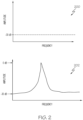
- the frequency response is illustrated in Figure 2 , wherein when there is no RFID tag present, there is a null condition 200.
- a null condition the coupling between loop 1 and loop 2 is very low.
- FIG. 2 shows -30dB with respect to full coupling 202. Then, when the RFID tag passes between the two loops (loop 1 and loop 2), the path is created and the transmission loss drops to a relative 0dB at the magnetic resonance point frequency.
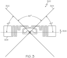
- Figure 3 shows an electrical field to electrical field transmission test system 300.
- the coupling between dipole 1 (302) and dipole 2 (304) is a minimum when their long directions are at 90 degrees.
- the angle to dipole 1 (302) shrinks to less than 90 degrees, so a voltage is induced into the antenna 308.
- This induced voltage can couple to dipole 2 (304) as it also has an angle to the long direction of the RFID tag 306 of less than 90 degrees (i.e., 45 degrees).
- the transmission response with and without an RFID tag 306 is as shown in Figure 2 .
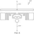
- Figure 4 shows an electrical field to magnetic field conversion system 400.
- Short dipole 1 (402) creates a near electric field with minimum magnetic field associated with it.
- the coupling between dipole 1 (402), which can be considered an electric field emitter, and loop 1 (404) which is a magnetic field receiver is inherently low.
- loop 1 (404) which is a magnetic field receiver
- the received electric field in the form of a differential voltage, causes a current to flow.
- the current flowing generates a magnetic field at the frequency of peak conversion that is detected by loop 1 (404) giving relatively strong coupling.
- FIG. 5 shows an alternative system 500.
- a dipole type antenna is driven by a source 502 such as a swept frequency generator or an RFID reader.
- a source 502 such as a swept frequency generator or an RFID reader.
- a number of RFID tags 504 and detecting loops 506 are in the near or radiating near field with respect to the dipole 508, (i.e., tags 1-4 (504) and loops 1-4 (506)).
- tags 1-4 (504) and loops 1-4 (506) the coupling between dipole 1 (508) and loops 1-4 (506) is a minimum, and with an RFID tag present, the coupling is greatly increased.
- the variable frequency source can be swept across a defined band at a certain rate. The time in the sweep when the signal on loops 1-4 (506) reaches a maximum is indicative of the peak coupling frequency of that tag. In this way, the peak coupling frequency of a number of RFID tags can be determined simultaneously, increasing the overall test speed.
- the RF signal having a variable field strength profile may be provided to one or more RFID devices moving through the test region by utilizing short-range techniques (e.g., near field coupling) and/or long-range techniques (e.g., far field transmission utilizing a radiating electromagnetic field).
- short-range techniques e.g., near field coupling
- long-range techniques e.g., far field transmission utilizing a radiating electromagnetic field
- an antenna of the RFID device may be viewed as having a near field region and a far field region.
- the near field region refers to a reactive near field and a radiating near field
- the far field region refers to a radiating far-field component.
- short-range communication generally involves the reactive near field, radiating near field, radiating far field, and/or a direct electrical connection
- long-range communication generally involves the radiating far field.
- the short-range couplers may couple via an electric field with the RFID device (e.g., in a capacitive fashion).
- the short-range couplers may couple via a magnetic field by utilizing a coil (e.g., single-turn coil or multi-turn coil) to couple with RFID device (e.g., in an inductive fashion).
- the short-range couplers may couple to the RFID device via an electric field, a magnetic field, or some combination of electric and magnetic fields (electromagnetic field), with the short-range couplers providing the appropriate structure (e.g., parallel plates, single or multi-turn coils, transmission lines, or other types of structures).
- the short-range couplers may provide short-range coupling in the near field via electric and/or magnetic fields or by direct connection with the RFID device.
Landscapes
- Engineering & Computer Science (AREA)
- Health & Medical Sciences (AREA)
- Physics & Mathematics (AREA)
- Toxicology (AREA)
- General Health & Medical Sciences (AREA)
- General Physics & Mathematics (AREA)
- Theoretical Computer Science (AREA)
- Computer Vision & Pattern Recognition (AREA)
- Electromagnetism (AREA)
- Artificial Intelligence (AREA)
- Computer Networks & Wireless Communication (AREA)
- Chemical & Material Sciences (AREA)
- Chemical Kinetics & Catalysis (AREA)
- Biomedical Technology (AREA)
- Electrochemistry (AREA)
- Life Sciences & Earth Sciences (AREA)
- Analytical Chemistry (AREA)
- Biochemistry (AREA)
- Immunology (AREA)
- Pathology (AREA)
- Near-Field Transmission Systems (AREA)
Claims (13)
- Système de test RFID magnétique (100), caractérisé en ce qu'il comprend :une première boucle de transmission (102) configurée pour transmettre un signal RF (de radiofréquence) ; etune deuxième boucle de réception (104) configurée pour recevoir le signal RF ; etune étiquette RFID (106) ;dans lequel un angle relatif entre la première boucle (102) et la deuxième boucle (104) qui est de 90 degrés pour alimenter en puissance le transfert du signal RF représentant un accouplement entre la première boucle (102) et la deuxième boucle (104) est au minimum ;dans lequel, lorsque l'étiquette RFID (106) est présente dans une zone d'accouplement du système de test RFID magnétique (100), l'angle devient inférieur à 90 degrés entre la première boucle (102) et l'étiquette RFID (106), et la première boucle (102) est configurée pour s'accoupler à un élément magnétique spécifique en fréquence de l'étiquette RFID (106) et pour induire un courant à l'élément magnétique spécifique en fréquence de l'étiquette RFID (106) ;dans lequel, sur la base du courant induit, l'élément magnétique spécifique en fréquence de l'étiquette RFID (106) est configuré pour créer un champ magnétique pour transmettre le signal RF ; etdans lequel, lorsque l'étiquette RFID (106) est présente dans la zone d'accouplement du système de test RFID magnétique (100), l'angle devient inférieur à 90 degrés entre l'étiquette RFID (106) et la deuxième boucle (104), et l'étiquette RFID (106) est configurée pour s'accoupler à la deuxième boucle (104).
- Système de test RFID magnétique (100) selon la revendication 1, dans lequel un niveau de signal de l'étiquette RFID (106) est configuré pour changer tandis que l'étiquette RFID (106) est configurée pour se déplacer à travers une région de test en faisant varier une distance entre les première et deuxième boucles (102, 104) et l'étiquette RFID (106).
- Système de test RFID magnétique (100) selon la revendication 1, dans lequel, lorsque l'angle relatif entre la première boucle (102) et l'étiquette RFID (106) est de 45 degrés, l'accouplement présente une magnitude de 0,707.
- Système de test RFID magnétique (100) selon la revendication 1, dans lequel, lorsque l'angle relatif entre la première boucle (102) et l'étiquette RFID (106) est de 0 degré, il existe alors un accouplement total avec un transfert de puissance maximal du signal RF entre la première boucle (102) et l'étiquette RFID (106).
- Système de test RFID magnétique (100) selon la revendication 1, dans lequel, lorsque l'étiquette RFID (106) comprenant l'élément magnétique est approximativement à 45 degrés par rapport à la deuxième boucle (104), l'étiquette RFID (106) s'accouple à la deuxième boucle (104) avec une magnitude de 0,0707 en créant un chemin pour l'étiquette RFID à un pic de fonctionnement magnétique.
- Système de test RFID magnétique (100) selon la revendication 1, dans lequel le système de test RFID magnétique (100) est configuré pour créer une condition nulle avec un transfert de puissance minimal du signal RF entre la première boucle (102) et la deuxième boucle (104) si aucune étiquette RFID (106) n'est présente.
- Système de test RFID magnétique (100) selon la revendication 6, dans lequel dans la condition nulle, l'accouplement entre la première boucle (102) et la seconde boucle (104) est approximativement de -30 dB par rapport à l'accouplement total.
- Système de test RFID magnétique (100) selon la revendication 5, dans lequel, lorsque l'étiquette RFID (106) passe entre la première boucle (102) et la deuxième boucle (104), un chemin est configuré pour être créé et une perte de transmission est configurée pour descendre à approximativement 0 dB à une fréquence de point de résonnance magnétique.
- Système de test RFID électrique (300), comprenant :un premier dipôle de transmission (302) configuré pour transmettre un signal RF ;un deuxième dipôle de réception (304) configuré pour recevoir le signal RF ; etune étiquette RFID (306) ; etdans lequel de longues directions entre le premier dipôle (302) et le deuxième dipôle (304) qui sont de 90 degrés pour alimenter en puissance le transfert du signal RF représentant un accouplement entre le premier dipôle (302) et le deuxième dipôle (304) sont au minimum ;le système de test RFID (300) étant caractérisé en ce quelorsque l'étiquette RFID (306) est présente dans une zone d'accouplement du système de test RFID électrique (300), un angle entre l'étiquette RFID (306) et le premier dipôle (302) est configuré pour se réduire à une valeur inférieure à 90 degrés qui induit une tension dans une antenne de l'étiquette RFID (306) ;dans lequel, sur la base de la tension induite, l'antenne de l'étiquette RFID (306) est configurée pour créer un champ électrique pour transmettre le signal RF ; etdans lequel, lorsque l'étiquette RFID (306) est présente dans la zone d'accouplement du système de test RFID électrique (300), l'angle devient inférieur à 90 degrés entre le deuxième dipôle et une longue direction de l'étiquette RFID (306), et l'étiquette RFID (306) est configurée pour s'accoupler au deuxième dipôle (304).
- Système de test RFID de conversion électrique à magnétique (400, 500), comprenant :un premier dipôle court (402, 508), qui est un émetteur de champ électrique qui est configuré pour créer un signal RF par un champ électrique proche avec un champ magnétique minimal associé à ce dernier ; etune étiquette RFID (504) ;le système (400, 500) étant caractérisé en ce qu'il comprendune première boucle de récepteur (404, 506), qui est un récepteur de champ magnétique configuré pour recevoir le signal RF ;dans lequel le transfert de puissance du signal RF représentant un accouplement entre le premier dipôle court (402, 508) et la première boucle de récepteur (404, 506) est au minimum ;dans lequel le système de test RFID magnétique de conversion électrique à magnétique (400, 500) est configuré de telle sorte que, lorsque l'étiquette RFID (504) est présente dans une zone d'accouplement du système de test RFID de conversion électrique à magnétique (400, 500) entre le premier dipôle court (402, 508) et la première boucle de récepteur (404, 506), le premier dipôle court (402, 508) est configuré pour induire une tension différentielle dans une antenne de l'étiquette RFID (504) et pour déclencher la circulation du courant dans l'antenne de l'étiquette RFID (504) ;dans lequel, sur la base du courant circulant dans l'antenne de l'étiquette RFID (504), l'antenne de l'étiquette RFID (504) est configurée pour créer un champ magnétique pour transmettre le signal RF ; etdans lequel, lorsque l'étiquette RFID (504) est présente dans la zone d'accouplement du système de test RFID de conversion électrique à magnétique (400, 500), l'étiquette RFID (504) est configurée pour s'accoupler à la première boucle de récepteur (404, 506).
- Système de test RFID de conversion électrique à magnétique (400, 500) selon la revendication 10, dans lequel, sur la base de la circulation de courant dans l'antenne de l'étiquette RFID (504), l'antenne de l'étiquette RFID (504) est configurée pour générer un champ magnétique à une fréquence de conversion de pic, qui est configurée pour être détectée par la première boucle (404, 506), qui est configurée pour donner lieu à un accouplement avec un transfert de puissance maximal du signal RF.
- Système de test RFID de conversion électrique à magnétique (400, 500) selon la revendication 11, dans lequel le premier dipôle court (402, 508) est configuré pour être entraîné par un générateur de fréquence variable (502) ou un lecteur RFID.
- Système de test RFID de conversion électrique à magnétique (400, 500) selon l'une quelconque des revendications 10 à 12, dans lequel une pluralité d'étiquettes (504) et de boucles de récepteur (506) sont configurées pour être positionnées en champ proche.
Applications Claiming Priority (2)
| Application Number | Priority Date | Filing Date | Title |
|---|---|---|---|
| US15/337,437 US10255468B2 (en) | 2016-10-28 | 2016-10-28 | Transmission RFID test systems |
| PCT/US2017/058717 WO2018081529A1 (fr) | 2016-10-28 | 2017-10-27 | Systèmes de test rfid de transmission |
Publications (2)
| Publication Number | Publication Date |
|---|---|
| EP3532982A1 EP3532982A1 (fr) | 2019-09-04 |
| EP3532982B1 true EP3532982B1 (fr) | 2023-11-22 |
Family
ID=60484447
Family Applications (1)
| Application Number | Title | Priority Date | Filing Date |
|---|---|---|---|
| EP17805314.6A Active EP3532982B1 (fr) | 2016-10-28 | 2017-10-27 | Systèmes de test rfid de transmission |
Country Status (4)
| Country | Link |
|---|---|
| US (1) | US10255468B2 (fr) |
| EP (1) | EP3532982B1 (fr) |
| CN (1) | CN109863498B (fr) |
| WO (1) | WO2018081529A1 (fr) |
Families Citing this family (12)
| Publication number | Priority date | Publication date | Assignee | Title |
|---|---|---|---|---|
| WO2019224575A1 (fr) | 2018-05-22 | 2019-11-28 | Tyco Fire & Security Gmbh | Étiquette souple allongée |
| US12223814B2 (en) | 2019-09-16 | 2025-02-11 | Sensormatic Electronics, LLC | Security tag for textiles using conductive thread |
| US11443160B2 (en) | 2019-09-18 | 2022-09-13 | Sensormatic Electronics, LLC | Systems and methods for laser tuning and attaching RFID tags to products |
| US10970613B1 (en) | 2019-09-18 | 2021-04-06 | Sensormatic Electronics, LLC | Systems and methods for providing tags adapted to be incorporated with or in items |
| US11055588B2 (en) | 2019-11-27 | 2021-07-06 | Sensormatic Electronics, LLC | Flexible water-resistant sensor tag |
| US12524640B2 (en) | 2019-11-27 | 2026-01-13 | Sensormatic Electronics, LLC | Flexible water-resistant sensor tag |
| US11755874B2 (en) | 2021-03-03 | 2023-09-12 | Sensormatic Electronics, LLC | Methods and systems for heat applied sensor tag |
| FI20216282A1 (en) * | 2021-12-16 | 2023-06-17 | Voyantic Oy | Method, arrangement and software product for testing a radio frequency transponder |
| US11869324B2 (en) | 2021-12-23 | 2024-01-09 | Sensormatic Electronics, LLC | Securing a security tag into an article |
| US11989615B2 (en) * | 2022-03-21 | 2024-05-21 | Wiliot, LTD. | Wireless tag testing |
| FI130390B (en) | 2022-05-06 | 2023-08-08 | Voyantic Oy | Apparatus and method for testing radio frequency sensors |
| US11880734B2 (en) | 2022-05-31 | 2024-01-23 | Wiliot, LTD. | Wireless tag testing |
Family Cites Families (13)
| Publication number | Priority date | Publication date | Assignee | Title |
|---|---|---|---|---|
| JP3578959B2 (ja) * | 2000-02-24 | 2004-10-20 | 松下電器産業株式会社 | テーブルタップおよびテーブルタップを用いた監視システム |
| US7307527B2 (en) | 2004-07-01 | 2007-12-11 | Avery Dennison Corporation | RFID device preparation system and method |
| US7609080B2 (en) * | 2005-03-22 | 2009-10-27 | Formfactor, Inc. | Voltage fault detection and protection |
| US7295117B2 (en) | 2005-04-07 | 2007-11-13 | Avery Dennison | RFID device test thresholds systems and methods |
| US7298267B2 (en) | 2005-05-09 | 2007-11-20 | Avery Dennison | RFID test interface systems and methods |
| US7298266B2 (en) | 2005-05-09 | 2007-11-20 | Avery Dennison | RFID communication systems and methods |
| DE102007034251B4 (de) * | 2007-07-23 | 2013-12-05 | Continental Automotive Gmbh | Fehleranalyseverfahren für eine Lambda-Sonde, Motorsteuerung für eine Brennkraftmaschine zur Ausführung des Fehleranalyseverfahrens sowie Programmspeicher |
| CN102422310B (zh) * | 2009-03-10 | 2015-11-25 | 沃尔玛百货有限公司 | 通用rfid标签和制造方法 |
| CN102025416B (zh) * | 2009-09-22 | 2013-12-04 | 华为技术有限公司 | 一种定位海缆故障的方法、中继器及通信系统 |
| EP2562548A4 (fr) * | 2010-04-23 | 2015-03-04 | Panasonic Corp | Dispositif de détection et système de détection |
| CN101859396B (zh) * | 2010-05-28 | 2012-05-23 | 中国科学院自动化研究所 | 一种rfid标签排列密度的基准测试系统及方法 |
| CN102880884B (zh) * | 2011-07-14 | 2015-12-09 | 航天信息股份有限公司 | 一种无源标签的测试系统和测试方法 |
| EP2574948B1 (fr) * | 2011-09-09 | 2017-08-30 | GS Yuasa International Ltd. | Surveillance de dispositif de stockage électrique |
-
2016
- 2016-10-28 US US15/337,437 patent/US10255468B2/en active Active
-
2017
- 2017-10-27 WO PCT/US2017/058717 patent/WO2018081529A1/fr not_active Ceased
- 2017-10-27 CN CN201780066125.6A patent/CN109863498B/zh active Active
- 2017-10-27 EP EP17805314.6A patent/EP3532982B1/fr active Active
Also Published As
| Publication number | Publication date |
|---|---|
| CN109863498B (zh) | 2022-09-09 |
| EP3532982A1 (fr) | 2019-09-04 |
| WO2018081529A1 (fr) | 2018-05-03 |
| CN109863498A (zh) | 2019-06-07 |
| US10255468B2 (en) | 2019-04-09 |
| US20180121690A1 (en) | 2018-05-03 |
Similar Documents
| Publication | Publication Date | Title |
|---|---|---|
| EP3532982B1 (fr) | Systèmes de test rfid de transmission | |
| EP1894029B1 (fr) | Systemes et procedes de test variables pour dispositif d'identification par radio frequence (rfid) | |
| EP1869481B1 (fr) | Systemes et procedes par seuils de test de dispositif d'identification par radiofrequence | |
| US7088248B2 (en) | System and method for selectively reading RFID devices | |
| US7298267B2 (en) | RFID test interface systems and methods | |
| KR20040021575A (ko) | 비접촉 데이터 캐리어 | |
| US9887464B2 (en) | Compact dipole antenna for RFID tag | |
| Buffi et al. | The SARFID technique for discriminating tagged items moving through a UHF-RFID gate | |
| US11526719B2 (en) | RFID tag having an integrated antenna coupled to test pads | |
| JP2013521737A (ja) | 正確な位置判定のためのrfタグ読取器 | |
| US10539608B2 (en) | Systems and methods for testing RFID straps | |
| US11346915B2 (en) | Device and method for determining the position of a transmitter relative to a detection region | |
| EP1869612B1 (fr) | Lecteur rfid avec antenne et procede de fonctionnement de ce lecteur | |
| US10935622B2 (en) | Apparatus and method for determining a position of a transmitter | |
| EP2486512B1 (fr) | Procédé et système pour l'essai de transpondeurs | |
| EP2923300B1 (fr) | Enregistrement d'une étiquette de transpondeur par l'intermédiaire d'un champ électromagnétique alternatif | |
| US20180307876A1 (en) | Rfid reader | |
| CN209641848U (zh) | 新型开放式门禁系统射频识别天线装置 | |
| KR20090128773A (ko) | 안테나 내장형 스피커 및 이를 구비한 이동통신 단말기 | |
| KR101129561B1 (ko) | 듀얼 알에프아이디 카드 | |
| WO2007017967A1 (fr) | Etiquette sans fil a circuit integre | |
| Roussos | Physics and Lower Layers |
Legal Events
| Date | Code | Title | Description |
|---|---|---|---|
| STAA | Information on the status of an ep patent application or granted ep patent |
Free format text: STATUS: UNKNOWN |
|
| STAA | Information on the status of an ep patent application or granted ep patent |
Free format text: STATUS: THE INTERNATIONAL PUBLICATION HAS BEEN MADE |
|
| PUAI | Public reference made under article 153(3) epc to a published international application that has entered the european phase |
Free format text: ORIGINAL CODE: 0009012 |
|
| STAA | Information on the status of an ep patent application or granted ep patent |
Free format text: STATUS: REQUEST FOR EXAMINATION WAS MADE |
|
| 17P | Request for examination filed |
Effective date: 20190418 |
|
| AK | Designated contracting states |
Kind code of ref document: A1 Designated state(s): AL AT BE BG CH CY CZ DE DK EE ES FI FR GB GR HR HU IE IS IT LI LT LU LV MC MK MT NL NO PL PT RO RS SE SI SK SM TR |
|
| AX | Request for extension of the european patent |
Extension state: BA ME |
|
| DAV | Request for validation of the european patent (deleted) | ||
| DAX | Request for extension of the european patent (deleted) | ||
| STAA | Information on the status of an ep patent application or granted ep patent |
Free format text: STATUS: EXAMINATION IS IN PROGRESS |
|
| 17Q | First examination report despatched |
Effective date: 20210318 |
|
| RAP3 | Party data changed (applicant data changed or rights of an application transferred) |
Owner name: AVERY DENNISON RETAIL INFORMATION SERVICES LLC |
|
| GRAP | Despatch of communication of intention to grant a patent |
Free format text: ORIGINAL CODE: EPIDOSNIGR1 |
|
| STAA | Information on the status of an ep patent application or granted ep patent |
Free format text: STATUS: GRANT OF PATENT IS INTENDED |
|
| INTG | Intention to grant announced |
Effective date: 20230523 |
|
| GRAS | Grant fee paid |
Free format text: ORIGINAL CODE: EPIDOSNIGR3 |
|
| GRAA | (expected) grant |
Free format text: ORIGINAL CODE: 0009210 |
|
| STAA | Information on the status of an ep patent application or granted ep patent |
Free format text: STATUS: THE PATENT HAS BEEN GRANTED |
|
| P01 | Opt-out of the competence of the unified patent court (upc) registered |
Effective date: 20231005 |
|
| AK | Designated contracting states |
Kind code of ref document: B1 Designated state(s): AL AT BE BG CH CY CZ DE DK EE ES FI FR GB GR HR HU IE IS IT LI LT LU LV MC MK MT NL NO PL PT RO RS SE SI SK SM TR |
|
| REG | Reference to a national code |
Ref country code: GB Ref legal event code: FG4D |
|
| REG | Reference to a national code |
Ref country code: CH Ref legal event code: EP |
|
| REG | Reference to a national code |
Ref country code: DE Ref legal event code: R096 Ref document number: 602017076791 Country of ref document: DE |
|
| REG | Reference to a national code |
Ref country code: IE Ref legal event code: FG4D |
|
| REG | Reference to a national code |
Ref country code: LT Ref legal event code: MG9D |
|
| REG | Reference to a national code |
Ref country code: NL Ref legal event code: MP Effective date: 20231122 |
|
| PG25 | Lapsed in a contracting state [announced via postgrant information from national office to epo] |
Ref country code: GR Free format text: LAPSE BECAUSE OF FAILURE TO SUBMIT A TRANSLATION OF THE DESCRIPTION OR TO PAY THE FEE WITHIN THE PRESCRIBED TIME-LIMIT Effective date: 20240223 |
|
| PG25 | Lapsed in a contracting state [announced via postgrant information from national office to epo] |
Ref country code: IS Free format text: LAPSE BECAUSE OF FAILURE TO SUBMIT A TRANSLATION OF THE DESCRIPTION OR TO PAY THE FEE WITHIN THE PRESCRIBED TIME-LIMIT Effective date: 20240322 |
|
| PG25 | Lapsed in a contracting state [announced via postgrant information from national office to epo] |
Ref country code: LT Free format text: LAPSE BECAUSE OF FAILURE TO SUBMIT A TRANSLATION OF THE DESCRIPTION OR TO PAY THE FEE WITHIN THE PRESCRIBED TIME-LIMIT Effective date: 20231122 |
|
| REG | Reference to a national code |
Ref country code: AT Ref legal event code: MK05 Ref document number: 1634504 Country of ref document: AT Kind code of ref document: T Effective date: 20231122 |
|
| PG25 | Lapsed in a contracting state [announced via postgrant information from national office to epo] |
Ref country code: NL Free format text: LAPSE BECAUSE OF FAILURE TO SUBMIT A TRANSLATION OF THE DESCRIPTION OR TO PAY THE FEE WITHIN THE PRESCRIBED TIME-LIMIT Effective date: 20231122 |
|
| PG25 | Lapsed in a contracting state [announced via postgrant information from national office to epo] |
Ref country code: AT Free format text: LAPSE BECAUSE OF FAILURE TO SUBMIT A TRANSLATION OF THE DESCRIPTION OR TO PAY THE FEE WITHIN THE PRESCRIBED TIME-LIMIT Effective date: 20231122 |
|
| PG25 | Lapsed in a contracting state [announced via postgrant information from national office to epo] |
Ref country code: ES Free format text: LAPSE BECAUSE OF FAILURE TO SUBMIT A TRANSLATION OF THE DESCRIPTION OR TO PAY THE FEE WITHIN THE PRESCRIBED TIME-LIMIT Effective date: 20231122 |
|
| PG25 | Lapsed in a contracting state [announced via postgrant information from national office to epo] |
Ref country code: NL Free format text: LAPSE BECAUSE OF FAILURE TO SUBMIT A TRANSLATION OF THE DESCRIPTION OR TO PAY THE FEE WITHIN THE PRESCRIBED TIME-LIMIT Effective date: 20231122 Ref country code: LT Free format text: LAPSE BECAUSE OF FAILURE TO SUBMIT A TRANSLATION OF THE DESCRIPTION OR TO PAY THE FEE WITHIN THE PRESCRIBED TIME-LIMIT Effective date: 20231122 Ref country code: IS Free format text: LAPSE BECAUSE OF FAILURE TO SUBMIT A TRANSLATION OF THE DESCRIPTION OR TO PAY THE FEE WITHIN THE PRESCRIBED TIME-LIMIT Effective date: 20240322 Ref country code: GR Free format text: LAPSE BECAUSE OF FAILURE TO SUBMIT A TRANSLATION OF THE DESCRIPTION OR TO PAY THE FEE WITHIN THE PRESCRIBED TIME-LIMIT Effective date: 20240223 Ref country code: ES Free format text: LAPSE BECAUSE OF FAILURE TO SUBMIT A TRANSLATION OF THE DESCRIPTION OR TO PAY THE FEE WITHIN THE PRESCRIBED TIME-LIMIT Effective date: 20231122 Ref country code: BG Free format text: LAPSE BECAUSE OF FAILURE TO SUBMIT A TRANSLATION OF THE DESCRIPTION OR TO PAY THE FEE WITHIN THE PRESCRIBED TIME-LIMIT Effective date: 20240222 Ref country code: AT Free format text: LAPSE BECAUSE OF FAILURE TO SUBMIT A TRANSLATION OF THE DESCRIPTION OR TO PAY THE FEE WITHIN THE PRESCRIBED TIME-LIMIT Effective date: 20231122 Ref country code: PT Free format text: LAPSE BECAUSE OF FAILURE TO SUBMIT A TRANSLATION OF THE DESCRIPTION OR TO PAY THE FEE WITHIN THE PRESCRIBED TIME-LIMIT Effective date: 20240322 |
|
| PG25 | Lapsed in a contracting state [announced via postgrant information from national office to epo] |
Ref country code: SE Free format text: LAPSE BECAUSE OF FAILURE TO SUBMIT A TRANSLATION OF THE DESCRIPTION OR TO PAY THE FEE WITHIN THE PRESCRIBED TIME-LIMIT Effective date: 20231122 Ref country code: RS Free format text: LAPSE BECAUSE OF FAILURE TO SUBMIT A TRANSLATION OF THE DESCRIPTION OR TO PAY THE FEE WITHIN THE PRESCRIBED TIME-LIMIT Effective date: 20231122 Ref country code: PL Free format text: LAPSE BECAUSE OF FAILURE TO SUBMIT A TRANSLATION OF THE DESCRIPTION OR TO PAY THE FEE WITHIN THE PRESCRIBED TIME-LIMIT Effective date: 20231122 Ref country code: NO Free format text: LAPSE BECAUSE OF FAILURE TO SUBMIT A TRANSLATION OF THE DESCRIPTION OR TO PAY THE FEE WITHIN THE PRESCRIBED TIME-LIMIT Effective date: 20240222 Ref country code: LV Free format text: LAPSE BECAUSE OF FAILURE TO SUBMIT A TRANSLATION OF THE DESCRIPTION OR TO PAY THE FEE WITHIN THE PRESCRIBED TIME-LIMIT Effective date: 20231122 Ref country code: HR Free format text: LAPSE BECAUSE OF FAILURE TO SUBMIT A TRANSLATION OF THE DESCRIPTION OR TO PAY THE FEE WITHIN THE PRESCRIBED TIME-LIMIT Effective date: 20231122 |
|
| PG25 | Lapsed in a contracting state [announced via postgrant information from national office to epo] |
Ref country code: DK Free format text: LAPSE BECAUSE OF FAILURE TO SUBMIT A TRANSLATION OF THE DESCRIPTION OR TO PAY THE FEE WITHIN THE PRESCRIBED TIME-LIMIT Effective date: 20231122 |
|
| PG25 | Lapsed in a contracting state [announced via postgrant information from national office to epo] |
Ref country code: CZ Free format text: LAPSE BECAUSE OF FAILURE TO SUBMIT A TRANSLATION OF THE DESCRIPTION OR TO PAY THE FEE WITHIN THE PRESCRIBED TIME-LIMIT Effective date: 20231122 |
|
| PG25 | Lapsed in a contracting state [announced via postgrant information from national office to epo] |
Ref country code: SK Free format text: LAPSE BECAUSE OF FAILURE TO SUBMIT A TRANSLATION OF THE DESCRIPTION OR TO PAY THE FEE WITHIN THE PRESCRIBED TIME-LIMIT Effective date: 20231122 |
|
| PG25 | Lapsed in a contracting state [announced via postgrant information from national office to epo] |
Ref country code: SM Free format text: LAPSE BECAUSE OF FAILURE TO SUBMIT A TRANSLATION OF THE DESCRIPTION OR TO PAY THE FEE WITHIN THE PRESCRIBED TIME-LIMIT Effective date: 20231122 Ref country code: SK Free format text: LAPSE BECAUSE OF FAILURE TO SUBMIT A TRANSLATION OF THE DESCRIPTION OR TO PAY THE FEE WITHIN THE PRESCRIBED TIME-LIMIT Effective date: 20231122 Ref country code: RO Free format text: LAPSE BECAUSE OF FAILURE TO SUBMIT A TRANSLATION OF THE DESCRIPTION OR TO PAY THE FEE WITHIN THE PRESCRIBED TIME-LIMIT Effective date: 20231122 Ref country code: IT Free format text: LAPSE BECAUSE OF FAILURE TO SUBMIT A TRANSLATION OF THE DESCRIPTION OR TO PAY THE FEE WITHIN THE PRESCRIBED TIME-LIMIT Effective date: 20231122 Ref country code: EE Free format text: LAPSE BECAUSE OF FAILURE TO SUBMIT A TRANSLATION OF THE DESCRIPTION OR TO PAY THE FEE WITHIN THE PRESCRIBED TIME-LIMIT Effective date: 20231122 Ref country code: DK Free format text: LAPSE BECAUSE OF FAILURE TO SUBMIT A TRANSLATION OF THE DESCRIPTION OR TO PAY THE FEE WITHIN THE PRESCRIBED TIME-LIMIT Effective date: 20231122 Ref country code: CZ Free format text: LAPSE BECAUSE OF FAILURE TO SUBMIT A TRANSLATION OF THE DESCRIPTION OR TO PAY THE FEE WITHIN THE PRESCRIBED TIME-LIMIT Effective date: 20231122 |
|
| REG | Reference to a national code |
Ref country code: DE Ref legal event code: R097 Ref document number: 602017076791 Country of ref document: DE |
|
| PLBE | No opposition filed within time limit |
Free format text: ORIGINAL CODE: 0009261 |
|
| STAA | Information on the status of an ep patent application or granted ep patent |
Free format text: STATUS: NO OPPOSITION FILED WITHIN TIME LIMIT |
|
| PGFP | Annual fee paid to national office [announced via postgrant information from national office to epo] |
Ref country code: GB Payment date: 20240912 Year of fee payment: 8 |
|
| PGFP | Annual fee paid to national office [announced via postgrant information from national office to epo] |
Ref country code: FR Payment date: 20240913 Year of fee payment: 8 |
|
| PG25 | Lapsed in a contracting state [announced via postgrant information from national office to epo] |
Ref country code: SI Free format text: LAPSE BECAUSE OF FAILURE TO SUBMIT A TRANSLATION OF THE DESCRIPTION OR TO PAY THE FEE WITHIN THE PRESCRIBED TIME-LIMIT Effective date: 20231122 |
|
| 26N | No opposition filed |
Effective date: 20240823 |
|
| PG25 | Lapsed in a contracting state [announced via postgrant information from national office to epo] |
Ref country code: SI Free format text: LAPSE BECAUSE OF FAILURE TO SUBMIT A TRANSLATION OF THE DESCRIPTION OR TO PAY THE FEE WITHIN THE PRESCRIBED TIME-LIMIT Effective date: 20231122 |
|
| PGFP | Annual fee paid to national office [announced via postgrant information from national office to epo] |
Ref country code: DE Payment date: 20240913 Year of fee payment: 8 |
|
| REG | Reference to a national code |
Ref country code: CH Ref legal event code: PL |
|
| PG25 | Lapsed in a contracting state [announced via postgrant information from national office to epo] |
Ref country code: MC Free format text: LAPSE BECAUSE OF FAILURE TO SUBMIT A TRANSLATION OF THE DESCRIPTION OR TO PAY THE FEE WITHIN THE PRESCRIBED TIME-LIMIT Effective date: 20231122 |
|
| PG25 | Lapsed in a contracting state [announced via postgrant information from national office to epo] |
Ref country code: BE Free format text: LAPSE BECAUSE OF NON-PAYMENT OF DUE FEES Effective date: 20241031 Ref country code: LU Free format text: LAPSE BECAUSE OF NON-PAYMENT OF DUE FEES Effective date: 20241027 |
|
| PG25 | Lapsed in a contracting state [announced via postgrant information from national office to epo] |
Ref country code: CH Free format text: LAPSE BECAUSE OF NON-PAYMENT OF DUE FEES Effective date: 20241031 |
|
| REG | Reference to a national code |
Ref country code: BE Ref legal event code: MM Effective date: 20241031 |
|
| PG25 | Lapsed in a contracting state [announced via postgrant information from national office to epo] |
Ref country code: FI Free format text: LAPSE BECAUSE OF FAILURE TO SUBMIT A TRANSLATION OF THE DESCRIPTION OR TO PAY THE FEE WITHIN THE PRESCRIBED TIME-LIMIT Effective date: 20231122 |
|
| PG25 | Lapsed in a contracting state [announced via postgrant information from national office to epo] |
Ref country code: IE Free format text: LAPSE BECAUSE OF NON-PAYMENT OF DUE FEES Effective date: 20241027 |
|
| PG25 | Lapsed in a contracting state [announced via postgrant information from national office to epo] |
Ref country code: CY Free format text: LAPSE BECAUSE OF FAILURE TO SUBMIT A TRANSLATION OF THE DESCRIPTION OR TO PAY THE FEE WITHIN THE PRESCRIBED TIME-LIMIT; INVALID AB INITIO Effective date: 20171027 |
|
| PG25 | Lapsed in a contracting state [announced via postgrant information from national office to epo] |
Ref country code: HU Free format text: LAPSE BECAUSE OF FAILURE TO SUBMIT A TRANSLATION OF THE DESCRIPTION OR TO PAY THE FEE WITHIN THE PRESCRIBED TIME-LIMIT; INVALID AB INITIO Effective date: 20171027 |