EP3533110B1 - Cornet d'émission à double polarisation - Google Patents
Cornet d'émission à double polarisation Download PDFInfo
- Publication number
- EP3533110B1 EP3533110B1 EP17808068.5A EP17808068A EP3533110B1 EP 3533110 B1 EP3533110 B1 EP 3533110B1 EP 17808068 A EP17808068 A EP 17808068A EP 3533110 B1 EP3533110 B1 EP 3533110B1
- Authority
- EP
- European Patent Office
- Prior art keywords
- horn
- radiator
- waveguide
- waveguides
- section
- Prior art date
- Legal status (The legal status is an assumption and is not a legal conclusion. Google has not performed a legal analysis and makes no representation as to the accuracy of the status listed.)
- Active
Links
Images







Classifications
-
- H—ELECTRICITY
- H01—ELECTRIC ELEMENTS
- H01Q—ANTENNAS, i.e. RADIO AERIALS
- H01Q21/00—Antenna arrays or systems
- H01Q21/06—Arrays of individually energised antenna units similarly polarised and spaced apart
- H01Q21/061—Two dimensional planar arrays
- H01Q21/064—Two dimensional planar arrays using horn or slot aerials
-
- H—ELECTRICITY
- H01—ELECTRIC ELEMENTS
- H01Q—ANTENNAS, i.e. RADIO AERIALS
- H01Q1/00—Details of, or arrangements associated with, antennas
- H01Q1/12—Supports; Mounting means
- H01Q1/22—Supports; Mounting means by structural association with other equipment or articles
- H01Q1/24—Supports; Mounting means by structural association with other equipment or articles with receiving set
-
- H—ELECTRICITY
- H01—ELECTRIC ELEMENTS
- H01Q—ANTENNAS, i.e. RADIO AERIALS
- H01Q13/00—Waveguide horns or mouths; Slot antennas; Leaky-waveguide antennas; Equivalent structures causing radiation along the transmission path of a guided wave
- H01Q13/02—Waveguide horns
-
- H—ELECTRICITY
- H01—ELECTRIC ELEMENTS
- H01Q—ANTENNAS, i.e. RADIO AERIALS
- H01Q13/00—Waveguide horns or mouths; Slot antennas; Leaky-waveguide antennas; Equivalent structures causing radiation along the transmission path of a guided wave
- H01Q13/02—Waveguide horns
- H01Q13/0208—Corrugated horns
- H01Q13/0225—Corrugated horns of non-circular cross-section
-
- H—ELECTRICITY
- H01—ELECTRIC ELEMENTS
- H01Q—ANTENNAS, i.e. RADIO AERIALS
- H01Q13/00—Waveguide horns or mouths; Slot antennas; Leaky-waveguide antennas; Equivalent structures causing radiation along the transmission path of a guided wave
- H01Q13/02—Waveguide horns
- H01Q13/025—Multimode horn antennas; Horns using higher mode of propagation
- H01Q13/0258—Orthomode horns
-
- H—ELECTRICITY
- H01—ELECTRIC ELEMENTS
- H01Q—ANTENNAS, i.e. RADIO AERIALS
- H01Q21/00—Antenna arrays or systems
- H01Q21/0006—Particular feeding systems
- H01Q21/0025—Modular arrays
-
- H—ELECTRICITY
- H01—ELECTRIC ELEMENTS
- H01Q—ANTENNAS, i.e. RADIO AERIALS
- H01Q21/00—Antenna arrays or systems
- H01Q21/06—Arrays of individually energised antenna units similarly polarised and spaced apart
-
- H—ELECTRICITY
- H01—ELECTRIC ELEMENTS
- H01Q—ANTENNAS, i.e. RADIO AERIALS
- H01Q21/00—Antenna arrays or systems
- H01Q21/24—Combinations of antenna units polarised in different directions for transmitting or receiving circularly and elliptically polarised waves or waves linearly polarised in any direction
-
- H—ELECTRICITY
- H01—ELECTRIC ELEMENTS
- H01Q—ANTENNAS, i.e. RADIO AERIALS
- H01Q25/00—Antennas or antenna systems providing at least two radiating patterns
-
- H—ELECTRICITY
- H01—ELECTRIC ELEMENTS
- H01Q—ANTENNAS, i.e. RADIO AERIALS
- H01Q25/00—Antennas or antenna systems providing at least two radiating patterns
- H01Q25/001—Crossed polarisation dual antennas
-
- H—ELECTRICITY
- H01—ELECTRIC ELEMENTS
- H01Q—ANTENNAS, i.e. RADIO AERIALS
- H01Q1/00—Details of, or arrangements associated with, antennas
- H01Q1/12—Supports; Mounting means
- H01Q1/22—Supports; Mounting means by structural association with other equipment or articles
- H01Q1/24—Supports; Mounting means by structural association with other equipment or articles with receiving set
- H01Q1/241—Supports; Mounting means by structural association with other equipment or articles with receiving set used in mobile communications, e.g. GSM
- H01Q1/246—Supports; Mounting means by structural association with other equipment or articles with receiving set used in mobile communications, e.g. GSM specially adapted for base stations
Definitions
- the present invention relates to a dual-polarized horn with a first and a second polarization, which are fed separately from one another via a first waveguide and a second waveguide.
- the present invention relates to such a dual-polarized horn antenna for use as a mobile radio antenna, in particular for a mobile radio base station.
- Horn radiators are also referred to as waveguide radiators and usually have a horn, ie a hollow body which is open on one side and is fed by a hollow line. Radiators based on waveguide technology usually have large dimensions and are therefore not suitable for a compact design. Therefore, horn radiators have hitherto been considered unsuitable for 3D beam steering and 3D beamforming applications, since a radiator spacing of less than 1 ⁇ , preferably less than 0.7 ⁇ , and in particular less than 0.5 ⁇ , is advantageous in the vertical and horizontal directions. Smaller individual emitter spacings improve the far-field group diagram in particular, since no secondary main lobes occur in the far-field group diagram with an individual emitter spacing of less than 0.5 ⁇ .
- Dual polarizing horn radiators pose a particular challenge in terms of compactness and electrical performance, since one radiator is used for two polarizations, which are usually different.
- compact dual-polarized horn antennas are fed through two separate orthogonal waveguides, or through a dual-polarized waveguide.
- WO 2015134772 A1 shows a waveguide structure for a dual polarized antenna array with septum polarizers that combine first waveguides associated with a first polarization and second waveguides associated with a second polarization and convert the like-polarization fields transmitted through the first and second waveguides into oppositely circularly polarized ones Convert fields and feed hollow radiators.
- two adjacent septum polarizers are each fed via a common waveguide, which has a cross section which, in projection onto the aperture plane, partially extends both in the area of the aperture of the one septum polarizer and in the area of the aperture of the horn radiator assigned to one septum polarizer.
- More horns are off CN 102 938 497 A , U.S. 2010/123636 A1 , RU 2 292 098 and DE 40 09 288 A1 famous.
- More horns are off DE 102010019081 A9 , KR 100801030 B1 , US2011267250A1 and DE 102010019081 A9 , the FR2523376A1 , the FR2599899A1 , the US7187342B2 , the WO 2007046055 A2 .
- horn radiators are known from the AT 202658 T , the DE 3375867 D1 , the DE 3787681 D1 , the AU688212B2 , the US4716415A , the CN 101083359B , the CN 201060943 Y , the US7564421B1 , the CN 203326116 U , the WO 2014208993 A1 , the EP 2869400 A1 , the WO 2008147132 A1 , the WO 2009008601 A1 , the KR 20090038803 A , the WO 2009093779 A1 , the KR 101090188 B1 and the US8988294B2 famous.
- the U.S. 5,818,396 shows a horn radiator fed by a coaxial structure.
- the waveguides guide linearly polarized light.
- the U.S. 2009/213022 A1 shows a horn radiator with a dielectric material inside the radiator and the U.S. 2010/078203 A1 discloses a low refractive index metamaterial.
- the present invention comprises a dual-polarized horn, with a first and a second polarization, which are fed separately from one another via a first waveguide and a second waveguide of the horn, the first and the second polarization being orthogonal to one another, for which the two waveguides have orthogonal polarizations in the region where they open into the horn.
- the first waveguide runs in the direction of emission to its mouth in the horn radiator and has a cross section which, in projection onto the aperture plane, extends partially inside and partially outside the aperture opening of the horn radiator, the mouth of the first Waveguide into the horn has along its long side an extension both parallel to the aperture plane and perpendicular to the aperture plane, with an outer short side of the mouth being arranged higher than the opposite inner short side of the mouth.
- the waveguides By routing the waveguide in the direction of radiation, the waveguides can be guided to the horn radiator in a confined space.
- the horn radiator By running partly inside and partly outside the aperture opening Cross-section, the horn radiator can be made very compact, since its minimum size is no longer limited by the cross-sections of the waveguide.
- the waveguide runs with its cross-section in projection onto the aperture plane partially under the aperture opening of an adjacent horn.
- the space available in a radiator array is optimally used and adjacent radiators are arranged next to one another in a very compact manner.
- the information on the extent of a cross section of the waveguide preferably relates to the cross section of the waveguide at the level of the lowest point of the mouth of the waveguide in the horn radiator with respect to a direction normal to the aperture plane.
- the waveguide has a boundary wall on the end face, which extends from a position which, in projection onto the aperture plane, lies outside the aperture opening of the horn radiator, to an edge of the opening into the horn radiator.
- the boundary wall is preferably the wall of a short side of the waveguide. This directs the electromagnetic field into the horn of the horn radiator.
- the boundary wall preferably runs at an angle to the aperture plane.
- the dual-polarized horn has a first and a second polarization, which are fed separately from one another via a first waveguide and a second waveguide.
- the two waveguides run in the direction of emission to their mouths in the horn radiator, with at least one of the waveguides and in particular the first waveguide having a transformation section through which its polarization in the aperture plane is rotated relative to the other waveguide before it flows into the horn radiator. This in turn enables a very compact arrangement of the waveguides.
- the two waveguides run next to one another and/or parallel to one another in the direction of emission to their openings into the horn antenna.
- the two waveguides initially have the same polarization before the polarization of one waveguide is rotated by the transformation section in the aperture plane in relation to the other waveguide.
- the transformation section has a twist, by which the polarization is rotated. Such twisting is also referred to as a twist.
- the polarization of the second waveguide is not rotated, or the second waveguide has a transformation section in which a transformation takes place at a different angle and in particular in the opposite direction than in the first waveguide.
- the second waveguide can therefore have no twist or a twist at a different angle than the first waveguide.
- the two waveguides can initially have the same polarization, with only the polarization of the first waveguide being rotated by 90° in order to be orthogonal to the polarization of the second waveguide in the region of the opening into the horn.
- the cross section of the first waveguide decreases in the transformation section.
- the second waveguide can have a transformation section in which its cross section is reduced.
- the two waveguides have a cross section with a long side and a short side, in particular a rectangular cross section.
- the waveguides have at least one narrowing of the cross section and/or at least one widening of the cross section.
- cross sections of adjacent waveguides can be nested in one another.
- a cross-sectional widening or an end section of the cross-section of a waveguide can engage in a cross-sectional narrowing of an adjacent waveguide.
- the second waveguides can have a cross-sectional narrowing, into which a cross-sectional widening or an end section of the cross-section of a first waveguide engages.
- a first waveguide can be arranged between two second waveguides with cross-section tapers, the cross-sectional widening or end sections of which engage in the cross-sectional tapers of the second waveguide on both sides.
- the narrowing or widening of the cross section is preferably provided in each case in a middle region of the waveguide cross section, in particular in a middle region with respect to the H-field plane.
- the waveguides can have the narrowing or widening of the cross section in the feed section and/or in the transformation section and/or in the mouth section.
- the long sides of the two waveguides preferably initially run parallel to one another. Alternatively or additionally, after the transformation section and in particular after the twisting, the long sides of the waveguides are perpendicular to one another. In particular, the long sides of the two waveguides in one Feed section run parallel to each other and are perpendicular to each other in a mouth section.
- the reduction in the cross section in the transformation section comprises at least a reduction in the short side and/or an increase in the ratio between the long and the short side.
- the horn radiator according to the invention is preferably a mobile radio transmitter, in particular for a mobile radio base station.
- Both waveguides are preferably routed to the horn radiator in the emission direction.
- the two waveguides run next to one another and/or parallel to one another in the direction of emission to their openings into the horn antenna.
- a course in the emission direction preferably means that the waveguide runs at an angle of less than 45°, preferably less than 30°, more preferably less than 10° to a normal on the aperture plane and/or to the main emission direction of the horn radiator.
- the waveguide particularly preferably runs in a direction which is perpendicular to the aperture plane and/or runs parallel to the main emission direction.
- the main emission direction is preferably perpendicular to the aperture plane of the horn radiator.
- the cross sections of the two waveguides are preferably rotated by 90° relative to one another in the region of the mouth.
- a section through the waveguide perpendicular to the course of the waveguide and/or a section in the aperture plane is preferably considered as a cross section.
- the mouth of one of the waveguides and in particular of the first waveguide in the horn radiator has an extension along its long side both parallel to the aperture plane and perpendicular to the aperture plane.
- one of the waveguides and in particular the first waveguide opens partially from the side and partially in the direction of emission into the horn radiator. This in turn enables optimal use of the available installation space.
- the long side of the orifice can have a first edge area running in the aperture plane and a second edge area running perpendicularly to the aperture plane.
- the long side of the opening of the waveguide is preferably arranged in a bottom region of the horn radiator that runs obliquely to the aperture plane and/or runs obliquely to the aperture plane.
- the base of the horn can have a funnel-shaped area and the mouth can be arranged on one side of the funnel-shaped area.
- an outer short side of the mouth is arranged higher than the opposite inner short side of the mouth.
- the extent parallel to the aperture plane and the extent perpendicular to the aperture plane can have a ratio of between 1:1 and 1:8, preferably between 1:2 and 1:5.
- the extent parallel to the aperture plane is between 0.05 ⁇ and 0.4 ⁇ , preferably between 0.1 ⁇ and 0.3 ⁇ .
- the extension perpendicular to the aperture plane can be between 0.05 ⁇ and 1.5 ⁇ , preferably between 0.4 ⁇ and 1.0 ⁇ .
- ⁇ is the wavelength of a center frequency of a resonant frequency range of the horn radiator, in particular a lowest resonant frequency range.
- one of the waveguides and in particular the second waveguide is guided in the emission direction to the horn radiator, with its cross section being located within the aperture opening in projection onto the aperture plane.
- the mouth of one of the waveguides and in particular of the second waveguide in the horn radiator is arranged centrally with respect to the aperture opening.
- the base of the horn radiator can have a funnel-shaped area and the opening of one of the waveguides and in particular of the second waveguide can be arranged at the tip of the funnel-shaped area.
- the dual polarized horn radiator according to the invention can have material cutouts and/or material introductions in at least one horn region, and in particular can have webs and/or steps and/or dielectrics running in the vertical direction.
- the horn radiator can in particular form a ridge waveguide radiator.
- the ridge waveguide radiator can be designed without side walls or have side walls.
- the webs preferably run in the vertical direction. More preferably, the distance between the inward facing edges of the webs increases in the height direction.
- the uprights can have a funnel shape and/or an exponential shape on their inward-facing side in the height direction.
- the horn radiator preferably has a resonant frequency range in a range between 10 GHz and 100 GHz, preferably between 25 GHz and 50 GHz, which is preferably the lowest resonant frequency range.
- the maximum diameter of the aperture opening of the horn radiator is between 0.3 ⁇ and 1.4 ⁇ , preferably between 0.5 ⁇ and 1.1 ⁇ , more preferably between 0.6 ⁇ and 0.9 ⁇ .
- the horn radiator has a height of between 0.5 ⁇ and 4 ⁇ , preferably between 1.5 ⁇ and 2.5 ⁇ .
- ⁇ is the wavelength of a center frequency of a resonant frequency range of the horn radiator, in particular a lowest resonant frequency range.
- the horn of the horn radiator has a first horn area with side walls running essentially in the main direction of emission and a second horn area with side walls that widen in a funnel shape, with the height of the second horn area being preferably smaller than the height of the first horn area and/or being preferred the widening of the aperture opening in the second horn area is less than 50%, more preferably less than 20%.
- the first and second horn areas can be continuous with one another.
- the horn has a hexagonal or round aperture and/or base.
- the present invention further comprises a radiator array comprising a plurality of dual-polarized radiator horns arranged side-by-side in a column or row, each of the horns being fed by a first and a second waveguide. It is provided that the waveguides in a column or row are each routed in the direction of emission to their openings in the horn antennas, with every second waveguide in the column or row having a transformation section through which its polarization is rotated in the aperture plane before it is in the Horn radiator opens.
- one waveguide and in particular the first waveguide of a horn radiator runs in the emission direction to its mouth in the horn radiator and that its cross section in projection onto the aperture plane runs at least partially below the aperture opening of an adjacent horn radiator, with the first and the second polarization are orthogonal to each other, for which the two waveguides have orthogonal polarizations in the region of their mouth in the horn.
- the radiator array is preferably a mobile radio antenna, in particular for a mobile radio base station.
- the individual radiator spacing in the column and/or row is less than 1 ⁇ , preferably less than 0.85 ⁇ , more preferably less than 0.75 ⁇ , more preferably less than 0.5 ⁇ .
- the horn radiators are arranged in a plurality of columns and/or rows arranged next to one another and the sum of the individual radiator spacing in the column or row and the individual radiator spacing perpendicular to the column or row is less than 2 ⁇ , preferably less than 1.7 ⁇ , more preferably less than 1.5 ⁇ .
- ⁇ is the wavelength of the center frequency of a resonant frequency range of the radiator array and in particular of the lowest resonant frequency range.
- the radiator array preferably comprises a plurality of dual-polarized horn radiators arranged next to one another, as have been described in more detail above.
- individual, several or all horns of the emitter array can have one or more of the features which were described above with regard to the horns according to the invention.
- the horns are arranged in several columns arranged next to one another or several rows arranged next to one another, with the horns of adjacent columns or rows preferably being arranged offset relative to one another, with the horns preferably being arranged in a honeycomb pattern.
- the radiator array has a feed network.
- the first waveguide and the second waveguide of the horn radiators arranged in a column or row have a bend to the side at different height levels of the feed network.
- the first waveguides of the horn radiators arranged in a column or row and/or the second waveguides of the horn radiators arranged in a column or row can each have a bend to the side in the same vertical plane.
- the waveguides of horn radiators arranged in two adjacent rows or columns can have a bend to the side at different height levels.
- the waveguides of the horn antennas are each fed individually.
- first waveguides of the horns arranged in a column or row and/or the second waveguides of the horns arranged in a column or row are connected to a common feed through a distributor.
- the present invention also includes group antennas consisting of a plurality of subarrays, which are designed as described above.
- the present invention further includes a cellular base station having one or more horn radiators as described above and/or one or more radiator arrays as described above.
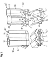
- FIG. 1 1 shows an embodiment of two dual polarized horns 20 and 20' according to the first aspect of the present invention.
- the two radiators thus simultaneously form an exemplary embodiment of a radiator array according to the invention.
- the two horn radiators 20 and 20' each have a horn, ie a hollow body which is open in the main direction of emission and via which electromagnetic waves are emitted or received.
- the horn is fed by waveguides, which are 1 are shown only with their end.
- the horn radiators 20 and 20' have two orthogonal polarizations which are fed by two separate waveguides 1 and 2 which via openings 23 and 24 into the horn of the respective horn radiator 20 and 20'.
- the polarizations of the two waveguides or of the electromagnetic waves guided through the waveguides are each perpendicular to one another in the area where the waveguides open into the horn radiator.
- the first waveguide 1 or 1' is guided to the hollow radiator from bottom to top, i.e. in the direction of emission, with its cross-section in the region of the opening into the horn radiator only partially coinciding with the aperture opening 22 of the hollow radiator 20 or 20', which it supplies with signals, and is partly outside the aperture opening.
- the waveguides 1 or 1′ preferably run in the main emission direction and/or perpendicular to the aperture plane.
- the first waveguide 1' which supplies the horn 20' with signals, is therefore partly below the aperture opening 22 of this horn 20', and partly below the aperture opening 22 of the adjacent horn 20.
- the cross section of the waveguide thus overlaps 1' in a projection onto the aperture plane partially with the aperture opening of its own radiator and partially with the aperture opening of an adjacent radiator.
- the horn radiators are fed partly from the side and partly from below via the first waveguide 1 or 1′.
- that part of the cross section of the first waveguide that runs below the aperture opening of the respective emitter is lengthened into the emitter for this purpose.
- the area of the cross section which runs outside the aperture opening and in particular in the area of the aperture opening of the adjacent radiator, on the other hand, is guided laterally into the horn radiator.
- the first waveguide 1 has a boundary wall 27 which extends obliquely upwards from a position outside the aperture opening of the horn to the mouth 23 in the horn.
- the boundary wall 27 is the wall of a short side of the first waveguide.
- the boundary wall 27 forms a base area of the adjacent horn radiator.
- the mouth 23 of the first waveguide 1 thus has both an extension 25 in a direction normal to the aperture plane and an extension 26 within the aperture plane.
- the opening 23 has a kink for this purpose, i.e. the opening is delimited by a vertical edge 25 and a horizontal edge 26.
- the orifice 23 can also have an edge running at an angle to the aperture plane.
- the opening 24, with which the second waveguide opens into the horn, is located completely within the aperture opening and the bottom area of the respective horn.
- the opening 24 is arranged centrally with respect to the aperture opening of the respective horn.
- the horn radiators each have a superimposition region 30 in which the two polarizations are superimposed and which is formed by the base of the horn and a wall region of the horn extending to the upper end of the mouth 23 of the waveguide.
- this is followed by a lower horn area 28, in which the horn extends essentially vertically upwards, ie in the main emission direction and/or perpendicular to the aperture plane, and an upper horn area 29, in which the horn widens outward.
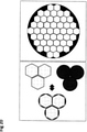
- horn radiators In 1 only two horn radiators according to the invention are shown as an example. Of course, however, more than two such radiators can also be arranged next to one another in a row or column. Furthermore, the horn radiators in the exemplary embodiment each have a 6-cornered basic shape, so that a honeycomb arrangement of several columns and rows next to one another is possible.
- FIG. 2 shows the concept underlying a dual polarized horn radiator or a corresponding radiator array according to the second aspect of the present invention.
- the two polarizations are fed via separate waveguides 1 and 2.
- the waveguides are guided parallel to one another in a feed section 3, with which they are connected to a feed network, and have the same orientation of the polarization there.
- the E-field is shown schematically as an arrow.
- the polarizations for the first and the second waveguide have a different orientation.
- the polarizations are perpendicular to one another.
- a transformation section is provided between the feed section 3 and the mouth section 5, which is used for field and/or impedance transformation.
- the first waveguide has a twist in the transformation section, as a result of which its polarization is rotated relative to the other waveguide.
- the waveguides 1 and 2 are guided from the feed section 3 via the transformation section 4 to the mouth section 5 in parallel from bottom to top, ie in the emission direction and in particular perpendicular to the aperture plane, so that the twisting in the region of the transformation section of the waveguide 1 causes its polarization to rotate in the aperture plane or about an axis of rotation perpendicular to the aperture plane.
- the second waveguide has no twisting in the transformation section 4, so that its polarization does not rotate.
- This arrangement has the advantage that the space available in the area of the feed section 3, which is connected to a matching network and/or a distribution network, can be optimally used.
- the first and second waveguides can be aligned identically in this area and/or have an identical cross section, and thus optimally utilize the available space.
- the waveguides are thus only aligned orthogonally to one another in the region of the mouth section 5 and therefore only require corresponding space there.
- the area of the waveguide cross-section in the transformation section decreases in the direction of the horn radiator. This is preferably the case both for the first and for the second waveguide.
- the area of the waveguide cross section in the direction of the antenna is therefore smaller than the area of the waveguide cross section in the direction of the distribution network.
- the waveguides therefore have a higher wave impedance and a higher lower limit frequency (cut-off frequency) in the direction of the antenna than in the direction of the distribution network.
- the transformation section with the waveguide cross-section change for field and impedance transformation has the advantage that orthogonally polarized radiator openings can be nested compactly on the antenna side, while a larger, broader bandwidth and lower-loss standard waveguide can be used on the side of the matching and/or distribution network.
- the matching network and/or distribution network can thus be designed to be broadband.
- the antenna side i.e. on the one hand the transformation section and the horn radiator, on the other hand, can be designed to be narrower and interchangeable.
- different transformation sections and different horns would be used for two different frequency ranges in the larger frequency range of the matching and/or distribution network.
- a first type of horn could be used for the frequency range between 27 GHz and 29 GHz and a second type of horn could be used for the frequency range between 37 GHz and 39 GHz.
- the overall system can have a modular structure, and in particular the matching and/or distribution network can be used for different applications.
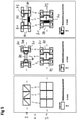
- FIG. 3 1 now shows a possible exemplary embodiment for a transformation section 4 for the first waveguide.
- a waveguide cross-section polarized in the x-direction which is connected to the feed section 3
- a waveguide cross-section polarized in the z-direction which is connected to the mouth section 5 .
- the cross-sectional area is reduced, in the exemplary embodiment, for example, from a waveguide cross-section of 7.11 mm ⁇ 3.55 mm and 572 ohms wave impedance to a waveguide cross-section of 6.11 mm ⁇ 2.4 mm and about 785 ohms wave impedance.
- the shape of the transformation section can be arbitrary between its two ends.
- three-dimensional curves can be partially or completely replaced by surfaces or steps, or the transformation section can be manufactured and assembled from two or more individual parts, depending on the manufacturing process.
- the transformation section 4 consists of two transformation elements 8 and 11, which each rotate the field by 45°, and an interposed intermediate element 9 with a constant cross section.
- the second waveguide does not have any twisting, but only experiences a cross-sectional reduction in the area of the transformation section. This serves to create sufficient space for the arrangement of the waveguides, which are orthogonal to one another in the mouth area.
- This is again based on 4 1 illustrates, which represents the transformation sections 6 and 7 of first and second waveguides 1 and 2 arranged next to one another in a column.
- the transformation sections 6 of the first waveguide 1 have a twist and a narrowing of the cross section
- the transformation sections 7 of the second waveguide 2 merely have a narrowing of the cross section.
- the narrowing of the cross section of the transformation sections 7 of the second waveguide creates the space that is required to allow the first waveguide 1 to be twisted.
- waveguides with a longer and a shorter side are used.
- the first and second waveguides are each arranged with their longer sides adjacent and parallel to one another. Due to the twisting of the first waveguides in the transformation section 4, however, the longer sides of the first and second waveguides are now perpendicular to one another in the mouth section 5.
- the shorter side of the first waveguide While only space for the shorter side of the first waveguide is required in the feed section 3 between the long sides of two second waveguides, space is required in the mouth area 5 for the longer side of a first waveguide. In order to create this space, in particular, the shorter side of the second waveguide further shortened. Furthermore, the longer side of the first waveguide can also be shortened.
- both the longer and the shorter side of the first and second waveguides are shortened, but the ratio between the longer and shorter side is increased, i.e. the shorter side is shortened more than the longer side in percentage terms.
- the waveguide becomes narrower in bandwidth.
- the cut-off frequency is not increased to the same extent.
- the waveguides have a ratio between the longer side and the shorter side of more than 1.5:1 and less than 2.5:1 on the side of the feed and/or distribution network and in particular in the feed section.
- the ratio between the longer and the shorter side is preferably greater than in the feed section, in particular greater than 2.5:1 and more preferably greater than 3:1. This achieves a good compromise between compactness and electrical properties.
- a waveguide with a rectangular cross section can be used according to the invention.
- the TE10(H10) mode is excited.
- waveguides with at least one narrowing of the cross section and/or at least one widening of the cross section in the E field plane and/or H field plane are also conceivable.
- waveguide variants with at least one narrowing of the cross section in the H-field level can be used, so-called ridge waveguides.
- the TE10 mode and/or a higher mode is preferably also excited.
- the waveguides already have a different polarization in the region of the feed section 3 . Furthermore, in the variant on the left, both the polarization of the first waveguide 1 and of the second waveguide 2 are rotated in the transformation section.
- the first and second waveguides in the feed section 3 each have oppositely aligned polarizations. These are each rotated by 45 degrees by corresponding transformation sections 4, so that they are orthogonal to one another in the mouth section.
- waveguides with an essentially square waveguide cross section are used in the opening section 5 . These are used as single-polarized 45-degree waveguides, in which the polarization runs diagonally.
- the waveguides 1 and 2 have different cross-sectional shapes, at least in the feed section 3 .
- the polarizations of the waveguides 1 and 2 are still aligned in the same direction in the feed section 3 .
- the first waveguide 1 has a partially widened rectangular waveguide cross-section in the feed section 3 and a partially narrowed rectangular waveguide cross-section in the H-plane in the mouth section 5 .
- the first waveguide has a cross-sectional widening 72 in a middle area with respect to the H-plane and a cross-sectional narrowing 70 in a middle area with respect to the now rotated H-plane in the mouth section 5.
- the second waveguide 2 has a partially narrowed rectangular waveguide cross-section in the H plane in the feed section 3 and in the mouth section 5 .
- the second waveguide 2 has a cross-sectional taper 70 in each case in a middle region with respect to the H-plane.
- waveguide 2 has the field characteristics of a double ridge waveguide.
- the polarization of the first waveguide 1 is rotated by 90 degrees and its cross-sectional shape and field distribution are changed by the transformation section 4, so that orthogonal polarizations with a similar field distribution result in the opening area 5.
- waveguide cross-sections with a significantly larger extension in the H-field plane than in the E-field plane are used.
- the cross-sectional areas of the waveguides are interleaved both in the feed section 3 and in the mouth section 5, in that a cross-sectional widening 72 or an end section 71 of one waveguide engages in a cross-sectional narrowing 70 of the other waveguide.
- the embodiment on the right in figure 5 shows a particularly compact variant.
- the first waveguide 1 has a partially widened and a partially filled rectangular waveguide cross-section in the H-plane with a cross-sectional widening 72 in a central region with respect to the H-plane.
- the polarization of the waveguide 1 is rotated by the transformation section 4 and its cross-sectional area is reduced.
- the cross-sectional shape and field distribution are essentially retained.
- the second waveguide 2 in turn has a partially narrowed rectangular waveguide cross-section in the H plane in the feed section 3 and in the mouth section 5 .
- the second waveguide 2 has a cross-sectional tapering 70 in each case in a middle region with respect to the H-plane.
- the ratio between the feed section 3 and the mouth section 5 increases between the width of the cross-section in the E-field plane in the wider end regions 71 and the cross-sectional taper 70.
- waveguide 1 and waveguide 2 have orthogonal polarization and different field distributions and/or field distribution densities in the opening section 5, which can lead to better decoupling and a more compact design, depending on the configuration of the superimposition region 30.
- the waveguides can have webs, material fillings, material cutouts, cross-section widening, cross-section constriction and many other measures for cost reduction and/or miniaturization and/or improvement of the electrical and mechanical properties.
- Both aspects of the present invention are preferably implemented, i.e. the first polarization is guided to the radiator centrally between two radiator openings and rotated via a transformation section. Furthermore, a change in the cross section of the waveguide is preferably provided in the transformation section, as a result of which the wave impedance changes.
- the polarization rotation is preferably implemented via a waveguide twisting, in particular via a waveguide twisting about an axis of rotation which is normal to the aperture plane.
- the waveguide cross-section is reduced in a direction normal to the aperture plane within the twisted waveguide, which leads to a change in wave impedance and more compact dimensions leads.
- the rotated radiator opening is preferably guided at least partially laterally into the radiator.
- FIG. 12 now shows a corresponding exemplary embodiment, in which the horn radiators are fed according to the first aspect in the manner already described above with regard to FIG 1 was presented.
- the waveguides are transformed as described above with regard to the exemplary embodiment in FIG Figures 2 to 4 was presented.
- the first and second waveguides described above with regard to the second aspect are connected with their mouth section 5 to the openings 23 or 24, via which the horn radiators are fed according to the first aspect of the present invention.
- the combination of the first and the second aspect has a very significant synergistic potential. This is because the combination of the first and second aspect makes it possible for the second waveguide 2 to open into the hollow radiator in the center with respect to the aperture opening 22 of the hollow radiator 20 or 20'. Nevertheless, the space available between the openings of the second waveguide is used optimally by the rotated opening areas of the first waveguide 1, since this opening area is not limited to the space available below the respective aperture opening, but extends under the respective aperture opening of the adjacent radiator.
- the transformation region 31 can have a height H1 of 0.5 ⁇ -1.5 ⁇ , for example, the superimposition region 30 used to superimpose the polarizations within the horn has a height H2 of 0.5 ⁇ -1.5 ⁇ , and the actual horn 32 a height H3 between 0.5 ⁇ and 4 ⁇ .
- the maximum diameter Da of the aperture opening 22, ie after the widening 29, can be 1.1 ⁇ 0.3 ⁇ , for example.
- ⁇ is in each case the wavelength of the center frequency of the lowest resonant frequency range of the radiator according to the invention.
- FIG 7a an alternative configuration of the overlapping region of the two polarizations is shown on the right.
- the opening 23 in this case has longer sides which run obliquely to the aperture plane and which connect the upper and lower narrow sides to one another.
- the opening has triangular side walls 33 for this purpose, which extend along the longer sides.
- wedge elements 34 are provided in the bottom area of the horn, which extend from the inside to the side walls. These preferably have the same shape as the boundary walls 27 for the mouth area of the adjacent first waveguide. As a result, the floor area has a funnel shape overall.
- the opening 24 for the second waveguide is arranged in the center of the funnel and, in the exemplary embodiment, cuts into the ramps 34.
- a possible dimension of the opening 23 for the first radiator is in Figure 7a indicated on the right.
- the opening 23 can have an extent B1 in the direction of its shorter side of 0.2 ⁇ + ⁇ 0.2 ⁇ .
- the extension in the vertical direction B3 can be 0.7 ⁇ +-0.7 ⁇ , the extension in the aperture plane B4 can be 0.2 ⁇ +-0.2 ⁇ .
- Figure 7b are three more cuts parallel to the aperture plane for the in Figure 7a illustrated embodiment shown.
- a section through the mouth region 5 is shown at the bottom right, ie just below the connection with the openings of the horn radiator.
- the narrow side can have a width B1 of 0.2 ⁇ + ⁇ 0.2 ⁇
- the longer side can have a width B2 of more than 0.5 ⁇ , for example 0.55 ⁇ .
- the longer side should not be less than 0.5 ⁇ with regard to the cut-off frequency.
- smaller dimensions and/or higher bandwidths are possible through the use of ridge waveguides and/or waveguides filled with dielectric.
- one or more webs can be arranged centrally in the waveguides in order to increase the bandwidth and/or reduce the cut-off frequency.
- the design of the superimposition area can also assume more complex forms.
- the wedge segments 34 can have material recesses and/or a ramp shape, in particular a ramp shape with an exponential progression.
- the radiator as in 8 shown, be designed as a ridge waveguide antenna.
- a ridge waveguide antenna 20" with side walls is shown on the left, and a ridge waveguide antenna 20′′′ without side walls is shown on the right.
- the horn of the ridge waveguide antenna 20" has the same configuration as shown above 1 and 6 was described in more detail.
- the ridge waveguide antenna 20′′′ has only the overlay region 30 described above, while only the ridges extend into the region of the actual horn and the side walls are missing there.
- the ridge waveguide antenna has ridges 75 which extend in the vertical direction.
- the webs 75 extend from the transition area 30 into the actual horn 32 .
- the webs are plate-shaped.
- the plate plane of the webs 75 runs radially to the central axis of the radiator and/or is perpendicular to the side wall along which it extends.
- the inner edges of the webs have a distance that increases towards the radiator opening.
- the webs 75 extend along the inner walls of the horn. In the exemplary embodiment on the left, they extend over the areas 28 and 29 to the radiator opening.
- FIG. 9 10 now shows an exemplary embodiment of the radiator array, which comprises four columns, each with eight individual radiators 20.
- the individual radiators are each designed as shown in 6 and 7, respectively.
- the corresponding design of the overlapping area in the floor area of the horn radiator is in 9 shown again in detail on the left.
- the array antenna shown can be, for example, an antenna with a center frequency of 28 GHz and a bandwidth of 2 GHz.
- the column spacing i.e. the individual radiator spacing in the z-direction
- the line spacing i.e. the individual radiator spacing in the x-direction
- the line spacing is 9.0 mm in the exemplary embodiment, i.e. 0.84 ⁇ at 28 GHz.
- first and second waveguides each have the same orientation and cross section, and are lined up along the columns, respectively. Furthermore, the reduced cross-section 5, rotated in the case of the first waveguides, can be seen in the mouth area, seen through the transformation section.
- Sections parallel to the aperture plane for different heights are shown again, a section through the feed section 3 being shown at the top left, a section through the transformation section 4 in the center left, and a section through the mouth section 5 being shown at the bottom left. Sections through the overlapping area, in which the opening 23 extends, are then shown at the top and in the middle on the right, and a section through the horn above the overlapping area at the bottom right.
- the E-field is shown for the two polarizations, at the top for port 24, ie a port fed by a second waveguide, and at the bottom for port 23, ie a port fed by a first waveguide.
- the horn radiators have a very good orthogonality of the two polarizations and a very even field distribution.
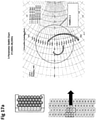
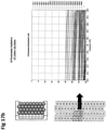
- 16a and 17a each show the fitting in the Smith chart, Figure 16b and 17b the isolation of the ports from each other.
- a VSWR of 2.0 ie an adjustment of more than 9.54 dB
- Figure 17a a VSWR of 1.5, ie an adjustment of more than 13.98 dB.
- the potential is actually much higher. In both cases, the decoupling is greater than 25 dB.
- In 18 shows the far field at 28 GHz and 32 GHz for ports P23 and P24.
- the far field is shown in the horizontal and vertical planes, with the phi component representing the co-polarization and the theta component representing the cross-polarization. These diagrams also show the excellent symmetry of the far field and the low cross-polarization.
- the individual emitters of adjacent columns are offset from one another.
- the radiators of a first column are arranged centrally between the radiators of the adjacent second column.
- the present invention also permits other basic forms of the radiator and/or a non-honeycomb arrangement.
- 19 shows two exemplary embodiments of radiator arrays according to the invention.
- An exemplary embodiment is shown on the left, which essentially corresponds to the exemplary embodiment already discussed above in 9 corresponds and has a honeycomb structure with hexagonal individual radiators.
- the individual emitters here, however, have an individual emitter spacing in the horizontal direction Dh of 0.75 ⁇ and an individual emitter spacing Dv in the vertical direction of 0.75 ⁇ , ie the individual emitters are slightly smaller than those in the exemplary embodiment in FIG 9 .
- the radiators have an individual radiator spacing in the horizontal direction Dh of 1 ⁇ and an individual radiator spacing in the vertical direction Dv of 0.5 ⁇ .
- spacer surfaces are arranged between the radiators within the column, by means of which the distance between the radiators within the radiator is increased and into which the radiators of the adjacent columns reach laterally.
- the columns can be arranged with a smaller column spacing.
- a hexagonal basic shape is again used, but an octagonal basic shape would also be conceivable here.
- the individual radiators instead of a basic hexagonal shape for the individual radiators, another configuration is also conceivable.
- the individual radiators have a circular basic shape, which is arranged partially overlapping.
- FIG. 20 right shows a radiator array with an approximately circular group aperture.
- An approximately circular arrangement of the individual radiators can, for example, lead to lower side lobes if the individual radiators with different amplitudes and phases are interconnected in the antenna diagram.
- the individual emitters of an emitter array according to the invention can be fed and/or adjusted individually, or partially interconnected in subgroups via a distribution and adjustment network.
- FIG. 21 shows an exemplary embodiment of a feed network for individual feeds on the left and for group feeds on the right.
- the distribution and matching networks shown can be connected to the feed sections of the first and second waveguides of the horn radiator according to the invention.
- first waveguide 1 and the second waveguide 2 of a column are brought out to the side in different planes.
- waveguides that supply different columns are also arranged in different planes.
- distributors 55, 56, 59 and 60 are provided, through which the first radiator 1 (distributor 55 or 59) and the second waveguide (distributor 56 or 60) of a column are interconnected. Via a further bend and filter 57, 58, 61 and 62, the distributors are then connected to a feed arranged on a PCB.
- the radiators according to the present invention are particularly suitable in a frequency range between 10 GHz and 100 GHz or for 5G applications, in particular applications with beam steering and/or beam forming.
Landscapes
- Engineering & Computer Science (AREA)
- Computer Networks & Wireless Communication (AREA)
- Waveguide Aerials (AREA)
- Variable-Direction Aerials And Aerial Arrays (AREA)
Claims (14)
- Cornet d'émission à double polarisation (20), en particulier pour une station de base radio mobile, comportant une première et une deuxième polarisation, qui sont alimentées séparément l'une de l'autre via un premier guide d'onde (1) et un deuxième guide d'onde (2) du cornet d'émission(20), dans lequel les première et deuxième polarisations sont orthogonales l'une par rapport à l'autre, pour lesquelles les deux guides d'ondes (1, 2) présentent une polarisation orthogonale au niveau de leur embouchure (23, 24) dans le cornet d'émission(20),moyennant quoi le premier guide d'ondes (1) s'étend dans la direction de rayonnement jusqu'à son embouchure (23) dans le cornet d'émission (20) et présente une section transversale qui, lorsqu'elle est projetée sur le plan d'ouverture, est projetée en partie à l'intérieur et en partie à l'extérieur de l'ouverture (22) du cornet d'émission (20),dans lequel l'embouchure (23) du premier guide d'ondes (1) dans le cornet d'émission (20) présente le long de son côté long un prolongement (25, 26) à la fois parallèle au plan d'ouverture et perpendiculaire au plan d'ouverture, dans lequel un côté court extérieur de l'embouchure est disposé plus haut que le côté court intérieur opposé de l'embouchure.
- Cornet d'émission à double polarisation selon la revendication 1, dans lequel le premier guide d'onde (1) présente une paroi de délimitation avant (27) qui s'étend d'une position qui, en projection sur le plan d'ouverture, se trouve à l'extérieur de l'ouverture (22) du cornet d'émission (20) jusqu'à un bord de l'embouchure (23) dans le cornet d'émission, moyennant quoi la paroi consiste de préférence en un côté court du premier guide d'ondes (1), dans lequel la paroi de délimitation(27) s'étend de préférence en oblique par rapport au plan d'ouverture.
- Cornet d'émission à double polarisation (20), notamment selon la revendication 1 ou 2, en particulier pour une station de base radio mobile, comportant une première et une deuxième polarisation, qui sont alimentées séparément l'une de l'autre via un premier guide d'ondes (1) et un deuxième guide d'ondes (2),
caractérisé en ce que les deux guides d'ondes (1, 2) s'étendent dans la direction d'émission jusqu'à leurs embouchures (23, 24) dans le cornet d'émission, au moins un des guides d'ondes et en particulier le premier guide d'ondes (1) présente une section de transformation (4), via laquelle sa polarisation est tournée dans le plan d'ouverture par rapport à l'autre guide d'ondes (2) avant de s'ouvrir dans le cornet d'émission(20) . - Cornet d'émission à double polarisation selon la revendication 3, dans lequel les deux guides d'ondes (1, 2) s'étendent côte à côte et/ou parallèlement l'un à l'autre dans le sens d'émission vers leurs embouchures (23, 24) dans le cornet d'émission (20) et présentent initialement la même polarisation et dans lequel la section de transformation (4) présente une torsion et dans lequel le deuxième guide d'ondes (2) ne présente pas de rotation de la polarisation ou une rotation à un angle différent de celui du premier guide d'ondes (1), pour lequel le deuxième guide d'ondes ne présente pas de torsion ou présente une autre torsion que le premier guide d'ondes (1),
et/ou dans lequel la section transversale du premier guide d'ondes (1) diminue dans la section de transformation (4) et dans lequel le deuxième guide d'ondes (2) présente une section de transformation (4), dans laquelle sa section transversale diminue. - Cornet d'émission à double polarisation selon la revendication 3 ou 4, dans lequel les deux guides d'ondes (1, 2) présentent une section transversale rectangulaire avec un côté long et un côté court, et/ou une section transversale avec au moins un rétrécissement de section transversale (70) et/ou au moins un élargissement de section transversale (72), dans lequel les côtés longs des deux guides d'ondes (1, 2) s'étendent initialement parallèlement l'un à l'autre, et dans lequel au moyen de la torsion, les côtés longs des guides d'ondes (1, 2) à l'extrémité de la section de transformation (4) sont perpendiculaires l'un à l'autre, et/ou dans lequel le rétrécissement (70) de la section transversale comprend au moins une diminution du côté court et/ou une augmentation du rapport entre le côté long et le côté court,
et/ou dans lequel la section de transformation (4) transforme au moins un élargissement de section (72) en un rétrécissement de section (70) et/ou inversement, et/ou dans lequel les sections de guides d'ondes adjacents (1, 2) sont imbriquées les uns dans les autres. - Cornet d'émission à double polarisation selon une des revendications précédentes, dans lequel un des guides d'onde et notamment le deuxième guide d'onde (2) est guidé dans la direction de rayonnement vers le cornet d'émission (20), dans lequel sa section transversale est projetée sur le plan d'ouverture à l'intérieur de l'ouverture (22) et/ou dans lequel l'embouchure (24) d'un des guides d'ondes et en particulier du deuxième guide d'ondes (2) dans le cornet d'émission(20) est disposée au centre par rapport à l'ouverture (22) et/ou dans lequel le bas du cornet d'émission (20) présente une zone en forme d'entonnoir et l'embouchure (24) d'un des guides d'ondes et en particulier du deuxième guide d'ondes (2) est disposée à l'extrémité de la zone en forme d'entonnoir.
- Cornet d'émission à double polarisation selon une des revendications précédentes, caractérisé en ce que,au moins une zone de cornet (28) possède des évidements de matière et/ou des insertions de matière, en particulier des nervures (75) et/ou des gradins et/ou des diélectriques qui s'étendent dans le sens vertical,et/ouen ce que le cornet d'émission (20ʺ, 20‴) forme un élément rayonnant à guide d'ondes faîtier avec ou sans parois latérales,et ouen ce que les nervures (75) présentent une forme d'entonnoir et/ou une forme exponentielle sur leur côté tourné vers l'intérieur dans le sens de la hauteur.
- Cornet d'émission à double polarisation selon une des revendications précédentes, dans lequel le cornet d'émission (20) présente une plage de fréquences de résonance dans une plage comprise entre 10 GHz et 100 GHz, de préférence entre 25 GHz et 50 GHz, dans lequel il s'agit de préférence de la plage de fréquence de résonance la plus basse, et/ou dans lequel le diamètre maximal de l'ouverture du cornet d'émission est comprise entre 0,3 λ et 1,4 λ, de préférence entre 0,5 À et 1,1 λ, plus préférentiellement entre 0,6 λ et 0,9 λ, et/ou le cornet d'émission présente une hauteur comprise entre 0,5 λ et 4 λ, de préférence entre 1,5 λ et 2,5 λ, dans lequel λ est la longueur d'onde de la fréquence centrale d'une plage de fréquences de résonance du cornet d'émission et en particulier la plage de fréquences de résonance la plus basse, et/ou dans lequel le cornet du cornet d'émission présente une première zone de cornet (28) avec des parois latérales s'étendant essentiellement dans la direction de rayonnement principale et une deuxième zone de cornet (29) avec des parois latérales s'élargissant en forme d'entonnoir, dans lequel la hauteur de la deuxième zone de cornet (29) est inférieure à la hauteur de la première zone de cornet (28) et/ou dans lequel l'élargissement de l'ouverture dans la deuxième zone de cornet est inférieur à 50 %, plus préférentiellement inférieur à 20 %, et/ou dans lequel les première et deuxième zones de cornet se confondent de façon continue et/ou dans lequel le cornet d'émission présente une ouverture hexagonale ou ronde.
- Réseau d'émetteurs, en particulier pour une station de base radio mobile, constitué d'une pluralité de cornets d'émission à double polarisation (20, 20') disposés les uns à côté des autres en colonne ou en rangée, dans lequel chacun des radiateurs à cornet est alimenté par un premier et un deuxième guide d'ondes (1, 2), dans lequel les guides d'ondes (1, 2) d'une colonne ou d'une rangée sont guidés chacun dans la direction de rayonnement vers leurs embouchures (23, 24) dans les cornets d'émission (20, 20'), dans lequel un guide d'ondes sur deux (2) dans la colonne ou la rangée présente une section de transformation (4) à travers laquelle sa polarisation est tournée dans le plan d'ouverture avant de s'ouvrir dans le cornet d'émission (20, 20'),etdans lequelun guide d'onde et en particulier le premier guide d'onde (1) d'un cornet d'émission (20, 20') dans la direction de rayonnement jusqu'à son embouchure (23) dans le cornet d'émission (20') est projeté sur le plan d'ouverture au moins partiellement en dessous de l'ouverture (22) d'un cornet d'émission adjacent (20), dans lequel la première et la deuxième polarisation sont orthogonales l'une par rapport à l'autre, pour lesquelles les deux guides d'onde (1, 2) présentent une polarisation orthogonale au niveau de leur embouchure (23, 24) dans le cornet d'émission.
- Réseau d'émetteurs selon la revendication 9, dans lequel les radiateurs à cornet (20, 20') présentent une plage de fréquences de résonance dans une plage comprise entre 10 GHz et 100 GHz, de préférence entre 25 GHz et 50 GHz, qui est de préférence la plage de fréquences de résonance la plus basse, et/ou dans lequel l'espacement des émetteurs individuels dans la colonne et/ou la ligne est inférieur à 1 λ, de préférence inférieur à 0,85 λ, plus préférablement inférieur à 0,75 λ, plus préférablement inférieur à 0,5 λ, et/ou dans lequel les cornets d'émission sont disposés en plusieurs colonnes et/ou rangées disposées les unes à côté des autres et la somme de l'espacement individuel des émetteurs dans la colonne ou rangée et l'espacement individuel des émetteurs perpendiculairement à la colonne ou à la rangée est inférieur à 2 λ, de préférence inférieur à 1,7 λ, plus préférablement inférieur à 1,5 λ, dans lequel λ désigne la longueur d'onde de la fréquence centrale d'une plage de fréquences de résonance du réseau d'émetteurs et en particulier de la plage de fréquences de résonance la plus basse.
- Réseau d'émetteurs selon une des revendications 9 ou 10, dans lequel le guide d'onde (1), qui est projeté par sa section transversale sur le plan d'ouverture au moins partiellement en dessous de l'ouverture (22) d'un cornet d'émission adjacente (20), est projeté en partie à l'intérieur et en partie à l'extérieur de l'ouverture (22) du cornet d'émission (20),
et/ou dans lequel le réseau d'émetteurs comprend une pluralité de cornets d'émission à double polarisation disposés côté à côté (20, 20') selon une des revendications 2 à 8. - Réseau d'émetteurs selon une des revendications 9 à 11, dans lequel les cornets d'émission (20, 20') sont disposés en plusieurs colonnes ou rangées juxtaposées les unes aux autres, de préférence les cornets d'émission de colonnes ou de rangées adjacentes sont disposés en décalage les uns par rapport aux autres, dans lequel les cornets d'émission sont de préférence disposés en nid d'abeille.
- Réseau d'émetteurs selon une des revendications 9 à 12 comportant un réseau d'alimentation (3), dans lequel les premiers guides d'ondes (1) et les deuxièmes guides d'ondes (2) des cornets d'émission (20, 20') disposés en colonne ou en rangée présentent un coude à différents niveaux de hauteur (51-54) vers le côté, dans lequel les premiers guides d'ondes des cornets d'émission disposés en colonne ou en rangée et/ou les deuxièmes guides d'ondes des cornets d'émission disposés en colonne ou en rangée présentent de préférence un coude (51-54) dans le même plan de hauteur vers le côté, et/ou dans lequel les guides d'ondes des cornets d'émission disposés en deux rangées ou colonnes adjacentes présentent un coude (51-54) vers le côté à différents niveaux de hauteur, et/ou
dans lequel les guides d'ondes (1, 2) des cornets d'émission sont chacun alimentés individuellement ou dans lequel les premiers guides d'ondes des cornets d'émission disposés en colonne ou en rangée et/ou les deuxièmes guides d'ondes des cornets d'émission disposés en colonne ou en rangée sont connectés via un distributeur (55, 56) avec une alimentation commune (57, 58). - Station de base radio mobile comportant un ou plusieurs cornets d'émission selon une des revendications 1 à 8 et/ou un ou plusieurs réseaux d'émetteurs selon une des revendications 9 à 13.
Applications Claiming Priority (2)
| Application Number | Priority Date | Filing Date | Title |
|---|---|---|---|
| DE102016014385.1A DE102016014385A1 (de) | 2016-12-02 | 2016-12-02 | Dual polarisierter Hornstrahler |
| PCT/EP2017/081124 WO2018100133A1 (fr) | 2016-12-02 | 2017-12-01 | Cornet d'émission à double polarisation |
Publications (2)
| Publication Number | Publication Date |
|---|---|
| EP3533110A1 EP3533110A1 (fr) | 2019-09-04 |
| EP3533110B1 true EP3533110B1 (fr) | 2022-03-16 |
Family
ID=60543549
Family Applications (1)
| Application Number | Title | Priority Date | Filing Date |
|---|---|---|---|
| EP17808068.5A Active EP3533110B1 (fr) | 2016-12-02 | 2017-12-01 | Cornet d'émission à double polarisation |
Country Status (6)
| Country | Link |
|---|---|
| US (1) | US11196178B2 (fr) |
| EP (1) | EP3533110B1 (fr) |
| KR (1) | KR20190086533A (fr) |
| CN (1) | CN110337758B (fr) |
| DE (1) | DE102016014385A1 (fr) |
| WO (1) | WO2018100133A1 (fr) |
Families Citing this family (7)
| Publication number | Priority date | Publication date | Assignee | Title |
|---|---|---|---|---|
| DE102016014385A1 (de) | 2016-12-02 | 2018-06-07 | Kathrein-Werke Kg | Dual polarisierter Hornstrahler |
| CN112290235A (zh) | 2019-07-24 | 2021-01-29 | 台达电子工业股份有限公司 | 天线阵列 |
| CN112290234A (zh) | 2019-07-24 | 2021-01-29 | 台达电子工业股份有限公司 | 通信装置 |
| CN110994195B (zh) * | 2019-12-24 | 2020-12-08 | 北京交通大学 | 一种空气波导平面阵列天线 |
| US12401128B2 (en) * | 2021-03-05 | 2025-08-26 | Huber+Suhner Ag | Waveguide antenna |
| US12512602B2 (en) * | 2022-01-31 | 2025-12-30 | European Space Agency | Waveguide feed array with overlapping clusters for use in a transmit/receive multiple-feed-per-beam single reflector antenna system |
| US12407980B2 (en) | 2023-03-01 | 2025-09-02 | Qsc, Llc | Customizable waveguides and associated systems and methods |
Citations (3)
| Publication number | Priority date | Publication date | Assignee | Title |
|---|---|---|---|---|
| US5818396A (en) * | 1996-08-14 | 1998-10-06 | L-3 Communications Corporation | Launcher for plural band feed system |
| US20090213022A1 (en) * | 2008-02-25 | 2009-08-27 | Lockheed Martin Corporation | Horn antenna, waveguide or apparatus including low index dielectric material |
| US20100078203A1 (en) * | 2008-09-30 | 2010-04-01 | Lockheed Martin Corporation | Low index metamaterial |
Family Cites Families (47)
| Publication number | Priority date | Publication date | Assignee | Title |
|---|---|---|---|---|
| GB551585A (en) | 1940-08-31 | 1943-03-02 | Marconi Wireless Telegraph Co | Electro-magnetic horn radiators |
| US2965898A (en) * | 1958-05-26 | 1960-12-20 | Rca Corp | Antenna |
| US2972148A (en) * | 1958-06-11 | 1961-02-14 | Bendix Corp | Multi-channel horn antenna |
| US3274604A (en) * | 1958-12-12 | 1966-09-20 | Bernard L Lewis | Multi-mode simultaneous lobing antenna |
| US4097869A (en) * | 1977-03-14 | 1978-06-27 | Stanford Research Institute | Orthogonal-port, biconical-horn, direction-finder antenna |
| US4246583A (en) * | 1979-03-16 | 1981-01-20 | Rca Corporation | Multimode feed for a monopulse radar |
| DE3111731A1 (de) * | 1981-03-25 | 1982-10-14 | Licentia Patent-Verwaltungs-Gmbh, 6000 Frankfurt | Mikrowellenuebertragungseinrichtung mit mehrmodendiversity-kombinationsempfang |
| FR2523376A1 (fr) | 1982-03-12 | 1983-09-16 | Labo Electronique Physique | Element rayonnant ou recepteur de signaux hyperfrequences a polarisations circulaires gauche et droite et antenne plane comprenant un reseau de tels elements juxtaposes |
| US4716415A (en) | 1984-12-06 | 1987-12-29 | Kelly Kenneth C | Dual polarization flat plate antenna |
| FR2599899B1 (fr) | 1986-06-05 | 1989-09-15 | Emmanuel Rammos | Antenne plane a reseau avec conducteurs d'alimentation imprimes a faible perte et paires incorporees de fentes superposees rayonnantes a large bande |
| ES2046211T3 (es) | 1986-06-05 | 1994-02-01 | Emmanuel Rammos | Elemento de antena con microcinta suspendida entre dos planos de masa autoportadores perforados de huecos radiantes superpuestos, y procedimiento de fabricacion. |
| US4797681A (en) * | 1986-06-05 | 1989-01-10 | Hughes Aircraft Company | Dual-mode circular-polarization horn |
| US4996535A (en) * | 1988-09-08 | 1991-02-26 | General Electric Company | Shortened dual-mode horn antenna |
| US4998113A (en) * | 1989-06-23 | 1991-03-05 | Hughes Aircraft Company | Nested horn radiator assembly |
| DE4009288C2 (de) | 1990-03-22 | 1994-03-03 | Siemens Ag | Rechteckhohlleiter mit E-H-Doppelversatz |
| ES2160698T3 (es) | 1994-02-26 | 2001-11-16 | Fortel Technology Ltd | Un procedimiento de fabricacion de una antena. |
| US5619216A (en) | 1995-06-06 | 1997-04-08 | Hughes Missile Systems Company | Dual polarization common aperture array formed by waveguide-fed, planar slot array and linear short backfire array |
| FI99221C (fi) | 1995-08-25 | 1997-10-27 | Nokia Telecommunications Oy | Planaarinen antennirakenne |
| GB9703748D0 (en) | 1997-02-22 | 1997-04-09 | Fortel International Limited | Microwave antennas |
| US6201508B1 (en) | 1999-12-13 | 2001-03-13 | Space Systems/Loral, Inc. | Injection-molded phased array antenna system |
| JP3739637B2 (ja) * | 2000-07-27 | 2006-01-25 | アルプス電気株式会社 | 一次放射器 |
| US7187342B2 (en) | 2003-12-23 | 2007-03-06 | The Boeing Company | Antenna apparatus and method |
| RU2292098C1 (ru) | 2005-06-29 | 2007-01-20 | Федеральное государственное унитарное предприятие "Особое конструкторское бюро МЭИ" | Многочастотная облучающая система зеркальной антенны с разделением ортогональных поляризаций |
| IL174549A (en) | 2005-10-16 | 2010-12-30 | Starling Advanced Comm Ltd | Dual polarization planar array antenna and cell elements therefor |
| WO2008069358A1 (fr) | 2006-12-08 | 2008-06-12 | Idoit Co., Ltd. | Antenne de type en réseau à cornet |
| KR20080105856A (ko) | 2007-06-01 | 2008-12-04 | 주식회사 아이두잇 | 듀얼선형편파 혼어레이 안테나 |
| CN101083359B (zh) | 2007-07-10 | 2012-05-09 | 中国电子科技集团公司第五十四研究所 | 高增益双线极化或双圆极化波导阵列天线制造方法 |
| CN201060943Y (zh) | 2007-07-10 | 2008-05-14 | 中国电子科技集团公司第五十四研究所 | 高增益双线极化或双圆极化波导阵列天线 |
| WO2009008601A1 (fr) | 2007-07-11 | 2009-01-15 | Idoit Co., Ltd. | Support pour antenne satellite |
| KR20090038803A (ko) | 2007-10-16 | 2009-04-21 | 주식회사 아이두잇 | 듀얼선형편파 혼어레이 안테나 및 이에 사용되는 혼 |
| WO2009093779A1 (fr) | 2008-01-25 | 2009-07-30 | Microface Co., Ltd | Structure de réseau d'alimentation pour antenne plate |
| US7564421B1 (en) | 2008-03-10 | 2009-07-21 | Richard Gerald Edwards | Compact waveguide antenna array and feed |
| US8125400B2 (en) | 2008-11-14 | 2012-02-28 | Norsat International Inc. | Compact antenna feed assembly and support arm with integrated waveguide |
| CN102414922B (zh) | 2009-04-30 | 2014-10-01 | Qest量子电子系统有限公司 | 用于卫星通信的宽带天线系统 |
| EP2330681A1 (fr) | 2009-12-07 | 2011-06-08 | European Space Agency | Dispositif OMT compact |
| KR101090188B1 (ko) | 2009-12-17 | 2011-12-06 | (주)마이크로페이스아이엔씨 | 평판형 회전편파 도파관 안테나 및 도파관의 꺽임 구조 |
| US8988294B2 (en) | 2011-12-06 | 2015-03-24 | Viasat, Inc. | Antenna with integrated condensation control system |
| US20150288068A1 (en) * | 2012-11-06 | 2015-10-08 | Sharp Kabushiki Kaisha | Primary radiator |
| CN102938497B (zh) | 2012-11-20 | 2014-12-17 | 北京遥测技术研究所 | 一种四频多极化共口径馈源 |
| KR101497678B1 (ko) | 2013-06-24 | 2015-03-09 | 주식회사 마이크로페이스 | 평판 배열 안테나용 듀얼 선형편파 혼 안테나 소자 |
| CN103390798B (zh) | 2013-07-26 | 2016-03-16 | 南京友乔电子科技有限公司 | 动中通卫星通信双极化四脊方喇叭阵列天线 |
| CN203326116U (zh) | 2013-07-26 | 2013-12-04 | 南京友乔电子科技有限公司 | 动中通卫星通信双极化四脊方喇叭阵列天线 |
| CN103474787B (zh) | 2013-07-30 | 2015-12-02 | 安徽四创电子股份有限公司 | 双极化平面阵列卫星电视接收天线 |
| FR3012917B1 (fr) | 2013-11-04 | 2018-03-02 | Thales | Repartiteur de puissance compact bipolarisation, reseau de plusieurs repartiteurs, element rayonnant compact et antenne plane comportant un tel repartiteur |
| EP3114732B1 (fr) | 2014-03-06 | 2020-08-26 | ViaSat, Inc. | Architecture de réseau de sources de guide d'ondes pour antennes réseau plan à cornet à double polarisation, discrètes, à large bande |
| CN104332714B (zh) * | 2014-11-13 | 2017-05-03 | 安徽四创电子股份有限公司 | 双极化斜波束波导缝隙阵列天线 |
| DE102016014385A1 (de) | 2016-12-02 | 2018-06-07 | Kathrein-Werke Kg | Dual polarisierter Hornstrahler |
-
2016
- 2016-12-02 DE DE102016014385.1A patent/DE102016014385A1/de not_active Ceased
-
2017
- 2017-12-01 KR KR1020197018203A patent/KR20190086533A/ko not_active Ceased
- 2017-12-01 WO PCT/EP2017/081124 patent/WO2018100133A1/fr not_active Ceased
- 2017-12-01 CN CN201780085268.1A patent/CN110337758B/zh active Active
- 2017-12-01 US US16/466,012 patent/US11196178B2/en active Active
- 2017-12-01 EP EP17808068.5A patent/EP3533110B1/fr active Active
Patent Citations (3)
| Publication number | Priority date | Publication date | Assignee | Title |
|---|---|---|---|---|
| US5818396A (en) * | 1996-08-14 | 1998-10-06 | L-3 Communications Corporation | Launcher for plural band feed system |
| US20090213022A1 (en) * | 2008-02-25 | 2009-08-27 | Lockheed Martin Corporation | Horn antenna, waveguide or apparatus including low index dielectric material |
| US20100078203A1 (en) * | 2008-09-30 | 2010-04-01 | Lockheed Martin Corporation | Low index metamaterial |
Also Published As
| Publication number | Publication date |
|---|---|
| EP3533110A1 (fr) | 2019-09-04 |
| WO2018100133A1 (fr) | 2018-06-07 |
| DE102016014385A1 (de) | 2018-06-07 |
| KR20190086533A (ko) | 2019-07-22 |
| US11196178B2 (en) | 2021-12-07 |
| US20200006863A1 (en) | 2020-01-02 |
| CN110337758B (zh) | 2021-11-12 |
| CN110337758A (zh) | 2019-10-15 |
Similar Documents
| Publication | Publication Date | Title |
|---|---|---|
| EP3533110B1 (fr) | Cornet d'émission à double polarisation | |
| EP3329545B1 (fr) | Antenne à double polarisation | |
| EP3411921B1 (fr) | Antenne à double polarisation | |
| EP3214695B1 (fr) | Antenne de téléphonie mobile | |
| EP2830156B1 (fr) | Émetteur de rayonnement à conducteur creux, émetteur de rayonnement de réseaux d'antennes et émetteur de rayonnement de radar à ouverture synthétique | |
| EP3220480B1 (fr) | Agencement de rayonnement dipolaire | |
| EP2929589B1 (fr) | Antenne omnidirectionnelle à double polarité | |
| DE102008023030B4 (de) | Radarantennenanordnung | |
| EP3306742A1 (fr) | Antenne radio mobile | |
| EP1749331B1 (fr) | Antenne de radiotelephonie mobile a element de formation de faisceau | |
| DE10012809A1 (de) | Dualpolarisierte Dipolantenne | |
| DE10203873A1 (de) | Dualpolarisierte Strahleranordnung | |
| WO2011113542A1 (fr) | Antenne omnidirectionnelle à large bande | |
| EP1964205B1 (fr) | Antenne a double polarisation avec maillons longitudinaux ou transversaux | |
| WO2015010760A1 (fr) | Réseau d'antennes à large bande | |
| DE102007047741A1 (de) | Speisenetzwerk für eine Gruppenantenne | |
| EP3756235B1 (fr) | Dispositif d'antennes à multiples bandes pour des applications de communications mobiles | |
| DE102015005468A1 (de) | Antenne | |
| DE3852981T2 (de) | Matrix aus koaxialen Leitungen mit planaren Überkreuzungen. | |
| WO2016050336A1 (fr) | Système d'émetteur multi-bandes | |
| EP1525642A1 (fr) | Reseau d'antennes bidimensionnel | |
| DE2810483C2 (de) | Antenne mit einem Schlitze aufweisenden Speisehohlleiter und einer mit diesem einen Winkel einschließenden Strahlerzeile | |
| DE3915048C2 (fr) | ||
| WO2000028623A1 (fr) | Antenne planaire dotee d'un reseau de couplage optimise |
Legal Events
| Date | Code | Title | Description |
|---|---|---|---|
| STAA | Information on the status of an ep patent application or granted ep patent |
Free format text: STATUS: UNKNOWN |
|
| STAA | Information on the status of an ep patent application or granted ep patent |
Free format text: STATUS: THE INTERNATIONAL PUBLICATION HAS BEEN MADE |
|
| PUAI | Public reference made under article 153(3) epc to a published international application that has entered the european phase |
Free format text: ORIGINAL CODE: 0009012 |
|
| STAA | Information on the status of an ep patent application or granted ep patent |
Free format text: STATUS: REQUEST FOR EXAMINATION WAS MADE |
|
| 17P | Request for examination filed |
Effective date: 20190531 |
|
| AK | Designated contracting states |
Kind code of ref document: A1 Designated state(s): AL AT BE BG CH CY CZ DE DK EE ES FI FR GB GR HR HU IE IS IT LI LT LU LV MC MK MT NL NO PL PT RO RS SE SI SK SM TR |
|
| AX | Request for extension of the european patent |
Extension state: BA ME |
|
| DAV | Request for validation of the european patent (deleted) | ||
| DAX | Request for extension of the european patent (deleted) | ||
| RAP1 | Party data changed (applicant data changed or rights of an application transferred) |
Owner name: ERICSSON AB |
|
| RAP1 | Party data changed (applicant data changed or rights of an application transferred) |
Owner name: TELEFONAKTIEBOLAGET LM ERICSSON (PUBL) |
|
| RAP1 | Party data changed (applicant data changed or rights of an application transferred) |
Owner name: TELEFONAKTIEBOLAGET LM ERICSSON (PUBL) |
|
| PUAG | Search results despatched under rule 164(2) epc together with communication from examining division |
Free format text: ORIGINAL CODE: 0009017 |
|
| STAA | Information on the status of an ep patent application or granted ep patent |
Free format text: STATUS: EXAMINATION IS IN PROGRESS |
|
| 17Q | First examination report despatched |
Effective date: 20210118 |
|
| B565 | Issuance of search results under rule 164(2) epc |
Effective date: 20210118 |
|
| RIC1 | Information provided on ipc code assigned before grant |
Ipc: H01Q 25/00 20060101ALI20210113BHEP Ipc: H01Q 1/24 20060101ALI20210113BHEP Ipc: H01Q 13/02 20060101ALI20210113BHEP Ipc: H01Q 21/24 20060101ALI20210113BHEP Ipc: H01Q 21/06 20060101AFI20210113BHEP Ipc: H01Q 21/00 20060101ALI20210113BHEP |
|
| GRAP | Despatch of communication of intention to grant a patent |
Free format text: ORIGINAL CODE: EPIDOSNIGR1 |
|
| STAA | Information on the status of an ep patent application or granted ep patent |
Free format text: STATUS: GRANT OF PATENT IS INTENDED |
|
| INTG | Intention to grant announced |
Effective date: 20211026 |
|
| GRAS | Grant fee paid |
Free format text: ORIGINAL CODE: EPIDOSNIGR3 |
|
| GRAA | (expected) grant |
Free format text: ORIGINAL CODE: 0009210 |
|
| STAA | Information on the status of an ep patent application or granted ep patent |
Free format text: STATUS: THE PATENT HAS BEEN GRANTED |
|
| AK | Designated contracting states |
Kind code of ref document: B1 Designated state(s): AL AT BE BG CH CY CZ DE DK EE ES FI FR GB GR HR HU IE IS IT LI LT LU LV MC MK MT NL NO PL PT RO RS SE SI SK SM TR |
|
| REG | Reference to a national code |
Ref country code: GB Ref legal event code: FG4D Free format text: NOT ENGLISH |
|
| REG | Reference to a national code |
Ref country code: CH Ref legal event code: EP |
|
| REG | Reference to a national code |
Ref country code: DE Ref legal event code: R096 Ref document number: 502017012797 Country of ref document: DE |
|
| REG | Reference to a national code |
Ref country code: IE Ref legal event code: FG4D Free format text: LANGUAGE OF EP DOCUMENT: GERMAN |
|
| REG | Reference to a national code |
Ref country code: AT Ref legal event code: REF Ref document number: 1476548 Country of ref document: AT Kind code of ref document: T Effective date: 20220415 |
|
| REG | Reference to a national code |
Ref country code: LT Ref legal event code: MG9D |
|
| REG | Reference to a national code |
Ref country code: NL Ref legal event code: MP Effective date: 20220316 |
|
| PG25 | Lapsed in a contracting state [announced via postgrant information from national office to epo] |
Ref country code: SE Free format text: LAPSE BECAUSE OF FAILURE TO SUBMIT A TRANSLATION OF THE DESCRIPTION OR TO PAY THE FEE WITHIN THE PRESCRIBED TIME-LIMIT Effective date: 20220316 Ref country code: RS Free format text: LAPSE BECAUSE OF FAILURE TO SUBMIT A TRANSLATION OF THE DESCRIPTION OR TO PAY THE FEE WITHIN THE PRESCRIBED TIME-LIMIT Effective date: 20220316 Ref country code: NO Free format text: LAPSE BECAUSE OF FAILURE TO SUBMIT A TRANSLATION OF THE DESCRIPTION OR TO PAY THE FEE WITHIN THE PRESCRIBED TIME-LIMIT Effective date: 20220616 Ref country code: LT Free format text: LAPSE BECAUSE OF FAILURE TO SUBMIT A TRANSLATION OF THE DESCRIPTION OR TO PAY THE FEE WITHIN THE PRESCRIBED TIME-LIMIT Effective date: 20220316 Ref country code: HR Free format text: LAPSE BECAUSE OF FAILURE TO SUBMIT A TRANSLATION OF THE DESCRIPTION OR TO PAY THE FEE WITHIN THE PRESCRIBED TIME-LIMIT Effective date: 20220316 Ref country code: BG Free format text: LAPSE BECAUSE OF FAILURE TO SUBMIT A TRANSLATION OF THE DESCRIPTION OR TO PAY THE FEE WITHIN THE PRESCRIBED TIME-LIMIT Effective date: 20220616 |
|
| PG25 | Lapsed in a contracting state [announced via postgrant information from national office to epo] |
Ref country code: LV Free format text: LAPSE BECAUSE OF FAILURE TO SUBMIT A TRANSLATION OF THE DESCRIPTION OR TO PAY THE FEE WITHIN THE PRESCRIBED TIME-LIMIT Effective date: 20220316 Ref country code: GR Free format text: LAPSE BECAUSE OF FAILURE TO SUBMIT A TRANSLATION OF THE DESCRIPTION OR TO PAY THE FEE WITHIN THE PRESCRIBED TIME-LIMIT Effective date: 20220617 Ref country code: FI Free format text: LAPSE BECAUSE OF FAILURE TO SUBMIT A TRANSLATION OF THE DESCRIPTION OR TO PAY THE FEE WITHIN THE PRESCRIBED TIME-LIMIT Effective date: 20220316 |
|
| PG25 | Lapsed in a contracting state [announced via postgrant information from national office to epo] |
Ref country code: NL Free format text: LAPSE BECAUSE OF FAILURE TO SUBMIT A TRANSLATION OF THE DESCRIPTION OR TO PAY THE FEE WITHIN THE PRESCRIBED TIME-LIMIT Effective date: 20220316 |
|
| PG25 | Lapsed in a contracting state [announced via postgrant information from national office to epo] |
Ref country code: SM Free format text: LAPSE BECAUSE OF FAILURE TO SUBMIT A TRANSLATION OF THE DESCRIPTION OR TO PAY THE FEE WITHIN THE PRESCRIBED TIME-LIMIT Effective date: 20220316 Ref country code: SK Free format text: LAPSE BECAUSE OF FAILURE TO SUBMIT A TRANSLATION OF THE DESCRIPTION OR TO PAY THE FEE WITHIN THE PRESCRIBED TIME-LIMIT Effective date: 20220316 Ref country code: RO Free format text: LAPSE BECAUSE OF FAILURE TO SUBMIT A TRANSLATION OF THE DESCRIPTION OR TO PAY THE FEE WITHIN THE PRESCRIBED TIME-LIMIT Effective date: 20220316 Ref country code: PT Free format text: LAPSE BECAUSE OF FAILURE TO SUBMIT A TRANSLATION OF THE DESCRIPTION OR TO PAY THE FEE WITHIN THE PRESCRIBED TIME-LIMIT Effective date: 20220718 Ref country code: ES Free format text: LAPSE BECAUSE OF FAILURE TO SUBMIT A TRANSLATION OF THE DESCRIPTION OR TO PAY THE FEE WITHIN THE PRESCRIBED TIME-LIMIT Effective date: 20220316 Ref country code: EE Free format text: LAPSE BECAUSE OF FAILURE TO SUBMIT A TRANSLATION OF THE DESCRIPTION OR TO PAY THE FEE WITHIN THE PRESCRIBED TIME-LIMIT Effective date: 20220316 Ref country code: CZ Free format text: LAPSE BECAUSE OF FAILURE TO SUBMIT A TRANSLATION OF THE DESCRIPTION OR TO PAY THE FEE WITHIN THE PRESCRIBED TIME-LIMIT Effective date: 20220316 |
|
| PG25 | Lapsed in a contracting state [announced via postgrant information from national office to epo] |
Ref country code: PL Free format text: LAPSE BECAUSE OF FAILURE TO SUBMIT A TRANSLATION OF THE DESCRIPTION OR TO PAY THE FEE WITHIN THE PRESCRIBED TIME-LIMIT Effective date: 20220316 Ref country code: IS Free format text: LAPSE BECAUSE OF FAILURE TO SUBMIT A TRANSLATION OF THE DESCRIPTION OR TO PAY THE FEE WITHIN THE PRESCRIBED TIME-LIMIT Effective date: 20220716 Ref country code: AL Free format text: LAPSE BECAUSE OF FAILURE TO SUBMIT A TRANSLATION OF THE DESCRIPTION OR TO PAY THE FEE WITHIN THE PRESCRIBED TIME-LIMIT Effective date: 20220316 |
|
| REG | Reference to a national code |
Ref country code: DE Ref legal event code: R097 Ref document number: 502017012797 Country of ref document: DE |
|
| PLBE | No opposition filed within time limit |
Free format text: ORIGINAL CODE: 0009261 |
|
| STAA | Information on the status of an ep patent application or granted ep patent |
Free format text: STATUS: NO OPPOSITION FILED WITHIN TIME LIMIT |
|
| PG25 | Lapsed in a contracting state [announced via postgrant information from national office to epo] |
Ref country code: DK Free format text: LAPSE BECAUSE OF FAILURE TO SUBMIT A TRANSLATION OF THE DESCRIPTION OR TO PAY THE FEE WITHIN THE PRESCRIBED TIME-LIMIT Effective date: 20220316 |
|
| 26N | No opposition filed |
Effective date: 20221219 |
|
| PG25 | Lapsed in a contracting state [announced via postgrant information from national office to epo] |
Ref country code: SI Free format text: LAPSE BECAUSE OF FAILURE TO SUBMIT A TRANSLATION OF THE DESCRIPTION OR TO PAY THE FEE WITHIN THE PRESCRIBED TIME-LIMIT Effective date: 20220316 |
|
| PG25 | Lapsed in a contracting state [announced via postgrant information from national office to epo] |
Ref country code: IT Free format text: LAPSE BECAUSE OF FAILURE TO SUBMIT A TRANSLATION OF THE DESCRIPTION OR TO PAY THE FEE WITHIN THE PRESCRIBED TIME-LIMIT Effective date: 20220316 |
|
| REG | Reference to a national code |
Ref country code: CH Ref legal event code: PL |
|
| REG | Reference to a national code |
Ref country code: BE Ref legal event code: MM Effective date: 20221231 |
|
| PG25 | Lapsed in a contracting state [announced via postgrant information from national office to epo] |
Ref country code: LU Free format text: LAPSE BECAUSE OF NON-PAYMENT OF DUE FEES Effective date: 20221201 |
|
| PG25 | Lapsed in a contracting state [announced via postgrant information from national office to epo] |
Ref country code: LI Free format text: LAPSE BECAUSE OF NON-PAYMENT OF DUE FEES Effective date: 20221231 Ref country code: IE Free format text: LAPSE BECAUSE OF NON-PAYMENT OF DUE FEES Effective date: 20221201 Ref country code: CH Free format text: LAPSE BECAUSE OF NON-PAYMENT OF DUE FEES Effective date: 20221231 |
|
| PG25 | Lapsed in a contracting state [announced via postgrant information from national office to epo] |
Ref country code: FR Free format text: LAPSE BECAUSE OF NON-PAYMENT OF DUE FEES Effective date: 20221231 Ref country code: BE Free format text: LAPSE BECAUSE OF NON-PAYMENT OF DUE FEES Effective date: 20221231 |
|
| REG | Reference to a national code |
Ref country code: AT Ref legal event code: MM01 Ref document number: 1476548 Country of ref document: AT Kind code of ref document: T Effective date: 20221201 |
|
| PG25 | Lapsed in a contracting state [announced via postgrant information from national office to epo] |
Ref country code: HU Free format text: LAPSE BECAUSE OF FAILURE TO SUBMIT A TRANSLATION OF THE DESCRIPTION OR TO PAY THE FEE WITHIN THE PRESCRIBED TIME-LIMIT; INVALID AB INITIO Effective date: 20171201 |
|
| PG25 | Lapsed in a contracting state [announced via postgrant information from national office to epo] |
Ref country code: AT Free format text: LAPSE BECAUSE OF NON-PAYMENT OF DUE FEES Effective date: 20221201 |
|
| PG25 | Lapsed in a contracting state [announced via postgrant information from national office to epo] |
Ref country code: CY Free format text: LAPSE BECAUSE OF FAILURE TO SUBMIT A TRANSLATION OF THE DESCRIPTION OR TO PAY THE FEE WITHIN THE PRESCRIBED TIME-LIMIT Effective date: 20220316 Ref country code: AT Free format text: LAPSE BECAUSE OF NON-PAYMENT OF DUE FEES Effective date: 20221201 |
|
| PG25 | Lapsed in a contracting state [announced via postgrant information from national office to epo] |
Ref country code: MK Free format text: LAPSE BECAUSE OF FAILURE TO SUBMIT A TRANSLATION OF THE DESCRIPTION OR TO PAY THE FEE WITHIN THE PRESCRIBED TIME-LIMIT Effective date: 20220316 |
|
| PG25 | Lapsed in a contracting state [announced via postgrant information from national office to epo] |
Ref country code: MC Free format text: LAPSE BECAUSE OF FAILURE TO SUBMIT A TRANSLATION OF THE DESCRIPTION OR TO PAY THE FEE WITHIN THE PRESCRIBED TIME-LIMIT Effective date: 20220316 |
|
| PG25 | Lapsed in a contracting state [announced via postgrant information from national office to epo] |
Ref country code: TR Free format text: LAPSE BECAUSE OF FAILURE TO SUBMIT A TRANSLATION OF THE DESCRIPTION OR TO PAY THE FEE WITHIN THE PRESCRIBED TIME-LIMIT Effective date: 20220316 Ref country code: MC Free format text: LAPSE BECAUSE OF FAILURE TO SUBMIT A TRANSLATION OF THE DESCRIPTION OR TO PAY THE FEE WITHIN THE PRESCRIBED TIME-LIMIT Effective date: 20220316 |
|
| PG25 | Lapsed in a contracting state [announced via postgrant information from national office to epo] |
Ref country code: MT Free format text: LAPSE BECAUSE OF FAILURE TO SUBMIT A TRANSLATION OF THE DESCRIPTION OR TO PAY THE FEE WITHIN THE PRESCRIBED TIME-LIMIT Effective date: 20220316 |
|
| PGFP | Annual fee paid to national office [announced via postgrant information from national office to epo] |
Ref country code: GB Payment date: 20251229 Year of fee payment: 9 |
|
| PGFP | Annual fee paid to national office [announced via postgrant information from national office to epo] |
Ref country code: DE Payment date: 20251229 Year of fee payment: 9 |