EP3533256B1 - Netzwerkknoten und verfahren darin zum aufbau einer beziehung zwischen benachbarten knoten - Google Patents
Netzwerkknoten und verfahren darin zum aufbau einer beziehung zwischen benachbarten knoten Download PDFInfo
- Publication number
- EP3533256B1 EP3533256B1 EP16919887.6A EP16919887A EP3533256B1 EP 3533256 B1 EP3533256 B1 EP 3533256B1 EP 16919887 A EP16919887 A EP 16919887A EP 3533256 B1 EP3533256 B1 EP 3533256B1
- Authority
- EP
- European Patent Office
- Prior art keywords
- network node
- random access
- information
- network
- access request
- Prior art date
- Legal status (The legal status is an assumption and is not a legal conclusion. Google has not performed a legal analysis and makes no representation as to the accuracy of the status listed.)
- Active
Links
Images


Classifications
-
- H—ELECTRICITY
- H04—ELECTRIC COMMUNICATION TECHNIQUE
- H04W—WIRELESS COMMUNICATION NETWORKS
- H04W76/00—Connection management
- H04W76/10—Connection setup
-
- H—ELECTRICITY
- H04—ELECTRIC COMMUNICATION TECHNIQUE
- H04W—WIRELESS COMMUNICATION NETWORKS
- H04W74/00—Wireless channel access
- H04W74/08—Non-scheduled access, e.g. ALOHA
-
- H—ELECTRICITY
- H04—ELECTRIC COMMUNICATION TECHNIQUE
- H04W—WIRELESS COMMUNICATION NETWORKS
- H04W92/00—Interfaces specially adapted for wireless communication networks
- H04W92/16—Interfaces between hierarchically similar devices
Definitions
- Embodiments herein relate generally to a first network node, a second network node, a third network node and to methods therein. In particular, embodiments herein relate to the establishment of a neighbour node relation.
- Communications devices such as terminals are also known as e.g. User Equipments (UEs), mobile terminals, stations (STAs), wireless devices, wireless terminals and/or mobile stations.
- Terminals are enabled to communicate wirelessly in a wireless communications network, such as a Wireless Local Area Network (WLAN) or a cellular communications network sometimes also referred to as a cellular radio system or cellular networks.
- WLAN Wireless Local Area Network
- the communication may be performed e.g. between two terminals, between a terminal and a regular telephone and/or between a terminal and a server via an access network and possibly one or more core networks, comprised within the wireless communications network.
- the above communications devices may further be referred to as mobile telephones, cellular telephones, laptops, tablets or sensors with wireless capability, just to mention some further examples.
- the communications devices in the present context may be, for example, portable, pocket-storable, hand-held, wall-mounted, computer-comprised, or vehicle-mounted mobile devices.
- the communications devices are enabled to communicate voice and/or data, via an access network, such as a Radio Access Network (RAN), with another entity, such as e.g. an Access Point (AP), another communications device or a server.
- RAN Radio Access Network
- AP Access Point
- the communications network covers an area, e.g. a geographical area, which is divided into subareas, such as coverage areas, cells or clusters.
- each cell area is served by an access node such as a base station, e.g. a Radio Base Station (RBS), which sometimes may be referred to as e.g. eNodeB (eNB), NodeB, B node, or Base Transceiver Station (BTS), depending on the technology and terminology used.
- RBS Radio Base Station
- eNB eNodeB
- NodeB NodeB
- BTS Base Transceiver Station
- the base stations may be of different classes such as e.g. macro eNodeB, home eNodeB, micro eNode B or pico base station, based on transmission power, functional capabilities and thereby also cell size.
- a traditional cell is the area where radio coverage is provided by the base station at a base station site.
- One base station situated on the base station site, may serve one or several cells. Further, each base station may support one or several communication technologies.
- the base stations communicate over the air interface operating on radio frequencies with the communications devices within range of the base stations.
- the expression Downlink (DL) is used for the transmission path from the base station to the communications device.
- the expression Uplink (UL) is used for the transmission path in the opposite direction i.e. from the communications device to the base station.
- a Universal Mobile Telecommunications System is a third generation (3G) telecommunication network, which evolved from the second generation (2G) Global System for Mobile Communications (GSM).
- the UMTS terrestrial radio access network (UTRAN) is essentially a RAN using wideband code division multiple access (WCDMA) and/or High Speed Packet Access (HSPA) for user equipments.
- WCDMA wideband code division multiple access
- HSPA High Speed Packet Access
- 3GPP Third Generation Partnership Project
- telecommunications suppliers propose and agree upon standards for third generation networks, and investigate enhanced data rate and radio capacity.
- 3GPP Third Generation Partnership Project
- radio network nodes may be connected, e.g., by landlines or microwave, to a controller node, such as a radio network controller (RNC) or a base station controller (BSC), which supervises and coordinates various activities of the plural radio network nodes connected thereto.
- RNC radio network controller
- BSC base station controller
- This type of connection is sometimes referred to as a backhaul connection.
- the RNCs and BSCs are typically connected to one or more core networks.
- the Evolved Packet System also called a Fourth Generation (4G) network
- EPS comprises the Evolved Universal Terrestrial Radio Access Network (E-UTRAN), also known as the Long Term Evolution (LTE) radio access network
- EPC Evolved Packet Core
- SAE System Architecture Evolution
- E-UTRAN/LTE is a variant of a 3GPP radio access network wherein the radio network nodes are directly connected to the EPC core network rather than to RNCs.
- the functions of an RNC are distributed between the radio network nodes, e.g. eNodeBs in LTE, and the core network.
- the RAN of an EPS has an essentially "flat" architecture comprising radio network nodes connected directly to one or more core networks, i.e. they are not connected to RNCs.
- the E-UTRAN specification defines a direct interface between the radio network nodes, this interface being denoted the X2 interface.
- Multi-antenna techniques can significantly increase the data rates and reliability of a wireless communication system. The performance is in particular improved if both the transmitter and the receiver are equipped with multiple antennas, which results in a Multiple-Input Multiple-Output (MIMO) communication channel.
- MIMO Multiple-Input Multiple-Output
- Such systems and/or related techniques are commonly referred to as MIMO systems.
- a design principle currently under consideration for the NX generation communications networks is to base it on an ultra-lean design. This implies avoidance of "always on signals" from the communications network as much as possible.
- Some examples of benefits from such design principle is expected to be a significantly lower network energy consumption, a better scalability, a higher degree of forward compatibility during the Radio Access Technology (RAT) evolution phase, a lower interference from system overhead signals and consequently higher throughput in low load scenario, and an improved support for user centric beam-forming.
- RAT Radio Access Technology
- AAS Advanced Antenna Systems
- MIMO Multiple Input Multiple Output
- the connected access nodes select a relevant set of mobility beams to transmit when required.
- Each mobility beam carries a unique Mobility Reference Signal (MRS).
- MRS Mobility Reference Signal
- the communications device e.g. the UE, is then instructed to measure on each MRS and report information relating to the performed measurement back to the communications network, e.g. to an access node. Based on some criteria, for example a difference between MRS strength between two mobility beams, a handover can be triggered.
- the involved Access Nodes ANs
- the involved Access Nodes need to maintain beam neighbour lists, exchange beam information, and coordinate MRS usage.
- Access Node e.g. base station
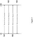
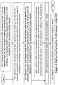
- the random access procedure in a wireless communication network is outlined in Figure 1 .
- a communications device e.g. a UE transmits a random access preamble to an access node, e.g. an eNB.
- the random access preamble allows the eNB, to estimate the transmission timing of the UE. Uplink synchronization is necessary as the UE otherwise cannot transmit any uplink data.
- Action 102 the communications network, e.g. by means of the eNB, transmits a Random Access Response (RAR) to the UE including a timing advance command to correct the uplink timing, based on the time of arrival measurement in Action 101.
- RAR Random Access Response
- Action 102 also assigns, a temporary identifier to the UE, and temporary identifier of the node, to be used in Action 103 in the random access procedure.
- the UE transmit a signal to the communications network in order to setup connection.
- the UE may transmit an RRC Connection Request to the eNB.
- a primary function of this message is to uniquely identify the UE. The exact content of this signaling depends on the state of the UE, e.g., whether it was previously known to the communications network or not.
- the communications network e.g. the eNB, performs contention resolution in case multiple UEs tried to access the communications network on the same resource.
- an RRC Connection Setup may be transmitted from the network, e.g. from the eNB, to the UE.
- a drawback with prior art solutions, such as the LTE solution, for establishing neighbour node relations is that they are based on the transmission of always-on signals, e.g. always-on reference signals. But the always-on signaling is absent or very sparse in a NX communications network by design and therefore are not very useful when establishing neighbor relations in a NX communications network which thus requires a different approach compared to the existing LTE solutions.
- WO2018/052343 A1 seems to disclose methods and arrangements relating to identification of neighboring network nodes.
- the communication device obtains and transmits the first identifier in an uplink to second network nodes/non-serving base stations. Receipt of the first identifier by a second network node enables identification of the first network node as neighboring said second network node.
- 3GPP documents R3-161902 and R2-132295 discuss further relevant technical details.
- the object is achieved by a method performed by a first network node for establishing a neighbour relation with a second network node.
- the first network node and the second network node are operating in a wireless communications network.
- the neighbour relation relates to a connection between two neighbouring nodes that are located within a radio coverage of each other.
- the first network node receives a random access request from a communications device operating in the wireless communications network.
- the first network node transmits, to a third network node operating in the wireless communications network, a first information.
- the first information relates to an identity of a preamble comprised in the received random access request and to a first reception time of the random access request.
- the first information is transmitted to the third network node.
- the transmission of the first information comprises, transmitting the first information when a signal strength of the received random access request is above a threshold value and transmitting, to the third network node, a request to configure the second network node to store the random access request when received by the second network node and to store a second information, which second information relates to the identity of a preamble comprised in the received random access request and to a second reception time of the received random access request when received by the second network node.
- the first network node establishes a neighbour relation with the second network node based on a neighbour node determination performed based on the first information and the second information received from the first network node and the second network node respectively by the third network node.
- the object is achieved by a first network node for establishing a neighbour relation with a second network node.
- the first network node and the second network node are configured to operate in a wireless communications network.
- the neighbour relation relates to a connection between two neighbouring nodes that are located within a radio coverage of each other.
- the first network node is configured to receive a random access request from a communications device operating in the wireless communications network.
- the first network node is configured to transmit, to a third network node operating in the wireless communications network, a first information.
- the first information is configured to relate to an identity of a preamble comprised in the received random access request and to a first reception time of the random access request.
- the first information is transmitted to the third network node.
- the transmission of the first information comprises, transmitting the first information when a signal strength of the received random access request is above a threshold value and transmitting, to the third network node, a request to configure the second network node to store the random access request when received by the second network node and to store a second information, which second information relates to the identity of a preamble comprised in the received random access request and to a second reception time of the received random access request when received by the second network node.
- the first network node is configured to establish a neighbour relation with the second network node based on a neighbour node determination performed based on the first information and the second information received from the first network node and the second network node respectively by the third network node.
- the object is achieved by a method performed by a second network node for establishing a neighbour relation with a first network node.
- the first network node and the second network node are operating in a wireless communications network.
- the neighbour relation relates to a connection between two neighbouring nodes that are located within a radio coverage of each other.
- the second network node receives a random access request from a communications device operating in the wireless communications network.
- the second network node receives from a third network node operating in the wireless communications network, a request to transmit to the third network node a second information.
- the second network node transmits, to the third network node, the second information.
- the second information relates to an identity of a preamble comprised in the received random access request and to a second reception time of the random access request.
- the second netweok node receives from the third network node, a request to store the received random access request and the second information.
- the second network node establishes a neighbour relation with the first network node based on a neighbour node determination performed based on the second information and a first information received from the second network node and the first network node respectively by the third network node.
- the object is achieved by a second network node for establishing a neighbour relation with a first network node.
- the first network node and the second network node are configured to operate in a wireless communications network.
- the neighbour relation relates to a connection between two neighbouring nodes that are located within a radio coverage of each other.
- the second network node is configured to receive a random access request from a communications device operating in the wireless communications network.
- the second network node receives from a third network node operating in the wireless communications network, a request to transmit to the third network node a second information.
- the second network node is configured to transmit, to the third network node, the second information.
- the second information relates to an identity of a preamble comprised in the received random access request and to a second reception time of the random access request.
- the second netweok node receives from the third network node, a request to store the received random access request and the second information.
- the second network node is configured to establish a neighbour relation with the first network node based on a neighbour node determination performed based on the second information and a first information received from the second network node and the first network node respectively by the third network node.
- the object is achieved by a method performed by a third network node for requesting establishment of a neighbour relation between a first network node and a second network node.
- the first network node and the second network node are operating in a wireless communications network.
- the neighbour relation relates to a connection between two neighbouring nodes that are located within a radio coverage of each other.
- the third network node receives, from the first network node, a first information.
- the first information relates to an identity of a preamble comprised in a random access request received by the first network node and to a first reception time of the received random access request.
- the third network node receives from the first network node, a request to configure the second network node to store the random access request when received by the second network node and to store a second information.
- the third network node receives, from the second network node, a second information.
- the second information relates to the identity of the preamble comprised in a random access request a random access request received by the second network node and to a second reception time of the received random access request.
- the third network node transmits to the second network node, a request to store the received random access request and information relating to the identity of the preamble comprised in the received random access request and relating to the reception time of the random access request.
- the third network node determines the first network node and the second network node as being neighbour nodes by determining that the first and second information relate to the same identity of the preamble; and determining that the first and second reception times are equal or almost equal, and requests the first network node and the second network node to establish a neighbour relation.
- the object is achieved by a third network node for requesting establishment of a neighbour relation between a first network node and a second network node.
- the first network node and the second network node are configured to operate in a wireless communications network.
- the neighbour relation relates to a connection between two neighbouring nodes that are located within a radio coverage of each other.
- the third network node is configured to receive, from the first network node, a first information.
- the first information relates to an identity of a preamble comprised in a random access request received by the first network node and to a first reception time of the received random access request.
- the third network node receives from the first network node, a request to configure the second network node to store the random access request when received by the second network node and to store a second information.
- the third network node is configured to receive, from the second network node, a second information.
- the second information relates to the identity of the preamble comprised in a random access request a random access request received by the second network node and to a second reception time of the received random access request.
- the third network node transmits to the second network node, a request to store the received random access request and information relating to the identity of the preamble comprised in the received random access request and relating to the reception time of the random access request.
- the third network node is configured to determine the first network node and the second network node as being neighbour nodes by determining that the first and second information relate to the same identity of the preamble; and determining that the first and second reception times are equal or almost equal, and request the first network node and the second network node to establish a neighbour relation.
- the object is achieved by a computer program, comprising instructions which, when executed on at least one processor, causes the at least one processor to carry out the method performed by the first network node.
- the object is achieved by a computer program, comprising instructions which, when executed on at least one processor, causes the at least one processor to carry out the method performed by the second network node.
- the object is achieved by a computer program, comprising instructions which, when executed on at least one processor, causes the at least one processor to carry out the method performed by the third network node.
- the object is achieved by a carrier comprising the computer program, wherein the carrier is one of an electronic signal, an optical signal, a radio signal or a computer readable storage medium.
- the first network node Since the first network node transmits the first information to the third network node, which first information relates to an identity of a preamble comprised in the received random access request and to a first reception time of the random access request, and since the first network node establishes a neighbour relation with the second network node based on a neighbour node determination performed by the third network node based on the first information, a simplified establishment of a neighbour node relation is provided. This results in an improved performance in the wireless communications network.
- An advantage with embodiments herein is that the prior art always-on signalling is not needed for establishment of a neighbour relation.
- the network nodes e.g. the first and second network nodes, may establish inter-node relations as well as beam relations.
- an advantage with embodiments herein is that the network nodes, e.g. the first and second network nodes, operating in the wireless communications network, e.g. a NX wireless communications network, may establish neighbour node relations without sacrificing the ultra-lean design principle, i.e., without needing to broadcast unique node identities.
- an advantage with embodiments herein is that the node relation establishment is transparent to the communications device. That is, the communications device will not be affected, in terms of e.g. quality of service, during the neighbour node relation establishment.
- An object addressed by embodiments herein is therefore how to improve performance in a wireless communications network.
- some embodiments disclosed herein relate to the establishment, e.g. the automatic establishment, of neighbour relations in the wireless communications network.
- embodiments herein provide a method to establish neighbour relations when a first network node, e.g. a new network node, such as a new NX network node, is installed in an existing wireless communications network, e.g. an existing NX communications network.
- a first network node e.g. a new network node, such as a new NX network node
- the first network node may be an existing network node, e.g. a network node already exiting in the wireless communications network, and which network node needs to find new neighbour relations. This may for example be the case when the physical environment is changes in the vicinity of the node, for example when a new building is constructed or a new road is opened.
- An idea used in the procedure is to use the slow start up of the first network node during which the first network node will listen to the random access requests from different communications devices, e.g. UEs, that it is able to hear.
- the first network node may report the random access requests it hears to a third network node to check which one or more second network nodes received the same random access preamble at the same point in time. Based on this information exchange the first network node may establish a neighbour relation with the one or more second network nodes. These one or more second network nodes is sometimes in this disclosure referred to as the first network node's neighbouring network nodes.
- the first network node may initially refrain from admitting the communications device in order to first identify any second network nodes, e.g. neighbouring network nodes, that may be able serve the communications device. After the determination of the neighbour node relations, the first network node may admit the communications device for communication. Thereby, the capacity of the wireless communications network is optimised while taking the energy consumption into consideration.
- Embodiments disclosed herein relate to recent technology trends that are of particular interest in a 5G context. However embodiments disclosed herein are applicable also in further development of the existing mobile broadband systems such as WCDMA and LTE.
- WCDMA Wideband Code Division Multiple Access
- WiMax Worldwide Interoperability for Microwave Access
- UMB Ultra Mobile Broadband
- GSM Global System for Mobile Communications
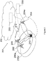
- Embodiments herein relate to a wireless communications network 200 as schematically illustrated in Figure 2 .
- the wireless communications network 200 may be a cellular communications network, such as e.g. a 5G network, an LTE network, a WCDMA network, an GSM network, any 3GPP cellular network, a WiMAX network , or any other wireless communications network or system.
- a cellular communications network such as e.g. a 5G network, an LTE network, a WCDMA network, an GSM network, any 3GPP cellular network, a WiMAX network , or any other wireless communications network or system.
- a core network 202 may be comprised in the wireless communications network 200.
- the core network 202 is configured to operate in the wireless communications network 200.
- the core network 202 may be a wireless core network such as a 5G core network, an LTE core network, e.g. an Evolved Packet Core (EPC) network; a WCDMA core network; a GSM core network; any 3GPP core network; WiMAX core network; or any cellular core network.
- EPC Evolved Packet Core
- a first network node 204 operates in the wireless communications network 200.
- the first network node 204 is sometimes in this disclosure referred to as a newly deployed node , and is thus a node that is newly installed to operate in the communications network 200.
- the first network node 204 may be an existing network node, e.g. a network node already exiting in the wireless communications network 200, and which network node needs to find new neighbour relations.
- the first network node 204 may be a radio access node such as a radio base station, for example an eNodeB, also denoted eNB, a Home eNodeB, or a NodeB or any other network node capable to serve a communications device 210 when located within a first area 204a , e.g. a first geographical area, in a communications network, such as the communications network 200.
- a first area 204a is sometimes referred to as a first coverage area, a first cell or a first cluster wherein the first network node 204 provides radio coverage, i.e. radio transmissions from the first network node 204 may be received within the first area 204a.
- the first network node 204 manages or is configured to manage communication with the communications devices 210 in the first area 204a.
- this is also referred to as the first network node 204 is associated with communications device 210 when it is located and/or operates within the first area 204a.
- first area 204a first coverage area 204a, first cell 204a and first cluster 204a may be used interchangeably.
- MSR Multi-Standard Radio
- MSR BS network controllers
- RNCs Radio Network Controllers
- BSCs Base Station Controllers
- BTSs Base Station Controllers
- APs Access Points
- transmission points transmission nodes
- RRUs Remote Radio Units
- RRHs Remote Radio Heads
- DAS Distributed Antenna System
- a second network node 206 operates in the wireless communications network 200.
- the second network node 206 is sometimes in this disclosure referred to as an existing node , and is thus a node operating in the communications network 200 before the introduction of the first network node 204 into the communications network 200.
- the second network node 206 may be a radio access node such as a radio base station, for example an eNodeB, also denoted eNB, a Home eNodeB, or a NodeB or any other network node capable to serve a communications device 210 when located within a second area 206a, e.g. a second geographical area, in a communications network, such as the communications network 200.
- a second area 206a is sometimes referred to as a second coverage area, a second cell or a second cluster wherein the second network node 206 provides radio coverage, i.e. radio transmissions from the second network node 206 may be received within the second area 206a.
- this is also specified as the second network node 206 manages or is configured to manage communication with the communications devices 210 in the second area 206a.
- this is also referred to as the second network node 206 is associated with communications device 210 when it is located and/or operates within the second area 206a.
- second area 206a second coverage area 206a, second cell 206a and second cluster 206a may be used interchangeably.
- MSR Multi-Standard Radio
- MSR BS network controllers
- RNCs Radio Network Controllers
- BSCs Base Station Controllers
- BTSs Base Station Controllers
- APs Access Points
- transmission points transmission nodes
- RRUs Remote Radio Units
- RRHs Remote Radio Heads
- DAS Distributed Antenna System
- One or more further second network nodes 206' may operate in the wireless communications network 200.
- the one or more further second network nodes 206' are sometimes in this disclosure referred to as one or more further existing nodes , and are thus nodes operating in the communications network 200 before the introduction of the first network node 204 into the communications network 200, or when the first network node 204 is an existing network node needing to find new neighbour relations due to for example changes in the physical environment.
- Each one of the one or more further second network nodes 206' may be a radio access node such as a radio base station, for example an eNodeB, also denoted eNB, a Home eNodeB, or a NodeB or any other network node capable to serve a communications device 210 when located within a respective further second area 206a', e.g. a further second geographical area, in a communications network, such as the communications network 200.
- each one of the one or more further second area 206a' is sometimes referred to as a further second coverage area, a further second cell or a further second cluster wherein one of the one or more further second network node 206' provides radio coverage, i.e.
- radio transmissions from the one or more further second network node 206' may be received within the respective further second area 206a'.
- this is also specified as each one of the one or more further second network nodes 206' manages or is configured to manage communication with the communications devices 210 in the respective further second area 206a'.
- this is also referred to as each one of the one or more of the further second network nodes 206' is associated with communications device 210 when it is located and/or operates within the respective further second area 206a'.
- further second area 206a' may be used interchangeably.
- further second coverage area 206a' may be used interchangeably.
- further second cell 206a and further second cluster 206a' may be used interchangeably.
- MSR Multi-Standard Radio
- MSR BS network controllers
- RNCs Radio Network Controllers
- BSCs Base Station Controllers
- BTSs Base Station Controllers
- APs Access Points
- transmission points transmission nodes
- RRUs Remote Radio Units
- RRHs Remote Radio Heads
- DAS Distributed Antenna System
- a third network node 208 operates in the wireless communications network 200.
- the third network node 208 is a central node that may operate in the core network 202, and then the third network node 208 may be a core network node or it may be comprised in the core network node.
- the core network node may be an Evolved-Serving Mobile Location Centre (E-SMLC), a Mobile Switching Center (MSC), a Mobility Management Entity (MME), an Operation & Maintenance (O&M) node, a Serving GateWay (S-GW), a Serving General Packet Radio Service (GPRS) Node (SGSN), etc.
- E-SMLC Evolved-Serving Mobile Location Centre
- MSC Mobile Switching Center
- MME Mobility Management Entity
- OFM Operation & Maintenance
- S-GW Serving GateWay
- GPRS General Packet Radio Service
- the third network node 208 may be arranged separately from and in communication with the core network 202.
- the third network node 208 corresponds to a node or is comprised in a node that operates in a so called computer cloud or computing cloud.
- the node operating in the cloud may be referred to as a cloud node, and thus the third network node 208 may correspond to the cloud node or the third network node 208 may be comprised in the cloud node.
- the computing cloud may also be referred to as a cloud system of servers or computers, or simply be named a cloud for providing certain service(s) to outside the cloud via a communication interface.
- the exact configuration of nodes etc. comprised in the cloud in order to provide said service(s) may not be known outside the cloud.
- the name "cloud” is often explained as a metaphor relating to that the actual device(s) or network element(s) providing the services are typically invisible for a user of the provided service(s), such as if obscured by a cloud.
- a communications device 210 operates in the wireless communications network 200.
- UE User Equipment
- the non-limiting term User Equipment (UE) refers to any type of communications device communicating with a network node in a communications network.
- Examples of communications devices are wireless devices, target devices, device to device UEs, machine type UEs or UEs capable of machine to machine communication, Personal Digital Assistants (PDA), iPADs, Tablets, mobile terminals, smart phones, Laptop Embedded Equipped (LEE), Laptop Mounted Equipment (LME), USB dongles etc.
- PDA Personal Digital Assistants
- iPADs iPADs
- Tablets Tablets
- smart phones smart phones
- LOE Laptop Embedded Equipped
- LME Laptop Mounted Equipment
- communications device wireless device and UE are used interchangeably.
- UE machine Type of Communication
- LoT Internet of Things
- CloT Cellular loT
- user equipment used in this document also covers other wireless devices such as Machine to Machine (M2M) devices, even though they do not have any user.
- MTC Machine Type of Communication
- LoT Internet of Things
- M2M Machine to Machine
- first network node 204 the second network node 206, the third network node 208 and the communications device 210 may operate for establishment of a neighbour relation
- first, second and third network nodes 204, 206, 208 and the communications device 210 are operating in the wireless communications network 200.
- the neighbour relation may be a node neighbour relation or a beam neighbour relation, wherein the node neighbour relation relates to a relation between neighbouring nodes and the beam neighbour relation relates to a relation between neighbouring beams.
- the neighbour relation may describe as a connection between two neighbouring nodes, e.g. between two neighbouring network nodes, or it may describe a connection between two beams.
- two network nodes may be considered as being neighbouring nodes when they are located within a radio coverage of each other and/or within radio coverage of the communication device 210.
- two beams may be considered as being neighbouring beams when they are located within a radio coverage of each other and/or within radio coverage of the communication device 210.
- the procedure depicted in Figure 3 comprises one or more of the following actions. It should be understood that these actions may be taken in any suitable order and that some actions may be combined.
- the third network node 208 may transmit, to the second network node 206, a request to store one or more random access preambles received and to store the point of time for each preamble reception, e.g. store the reception time for each received random access preamble.
- the third network node 208 may transmit to, the first network node 204, a request to store one or more random access preambles received and to store the point of time for each preamble reception, e.g. store the reception time for each received random access preamble.
- the third network node 208 optionally configures a newly deployed node, e.g. the first network node 204, and/or a set of existing nodes, e.g. one or more of second nodes 206, 206', in the vicinity of the new node, to store the received random access preamble and the corresponding time stamp of receiving it.
- a newly deployed node e.g. the first network node 204
- a set of existing nodes e.g. one or more of second nodes 206, 206'
- the third network node 208 may also instruct the first and/or second network nodes 204, 206 to transmit collected information to it.
- information relating to received preambles may be used by the third network node 208 to determine neighbour node relations, i.e. to determine if the first and second network nodes 204, 206 are neighbouring nodes.
- the communications device 210 transmits a Random Access (RA) with a random access preamble.
- RA Random Access
- the random access preamble is referred to as a preamble_A.
- the transmitted random access preamble may be received by the first network node 204 and by the second network node 206. It should be understood that the point of time of the respective reception may be different.
- the communications device 210 performs the random access in order to connect to the communications network 200. It is assumed that the communications device 210 is within the coverage area of the newly deployed node, e.g. within the first coverage area 204a of the first network node 204. Further, it is assumed that the random access from the communications device 210 is heard by the first network node 204 and also by one or more of the existing nodes, e.g. by one or more second network node 206, 206'. The communications device 210 picks a random access preamble preamble_A randomly amongst the whole set of preambles for the initial access.
- the first and second network nodes 204, 206,206' may store the received random access request, the preamble preamble_A and the point of time T of their respective reception. As mentioned above, this may be done in order to be able to report this information to the third network node 208, either mandatory, optionally or upon request.
- the first network node 204 may generate a report based on the received information about the random access related content.
- the report may comprise information about the preamble preamble_A such as the identity of the preamble, and information about the point of time T when the preamble was received by the first network node 204.
- the one or more second network nodes 206,206' may generate a report as described above.
- the first network node 204 transmits the generated report to the third network node 208.
- the third network node 208 is capable of identifying the one or more second network nodes 206, 206' that was/were able to hear the random access with the mentioned preamble preamble_A at the same or similar point of time.
- similar point of time is meant so close to each other that the difference in time corresponds to the different distances of the propagation paths from the communications device 210 and the first network node 204 and the one or more second network nodes 206, 206' respectively.
- the one or more second network nodes 206, 206' transmit a Random Access Response (RAR) towards the communications device 210.
- RAR Random Access Response
- the first network node 204 may transmit a random access response towards the communications device 210. This may be perform alternatively or additionally to the random access response transmitted from the one or more second network nodes 206,206'.
- the first and second network nodes 204,206,206' may transmit the random access response on a Downlink Shared Channel (DL-SCH).
- the random access response may address the communications device 210 with a Random Access Radio Network Temporary Identifier (RA-RNTI) but the random access response may also assign a Temporary Cell RNTI (C-RNTI).
- RA-RNTI Random Access Radio Network Temporary Identifier
- C-RNTI Temporary Cell RNTI
- the random access response may also send a timing adjustment to correct the uplink timing from the communications device 210.
- the random access response may assign resources to the communications device 210 terminal for uplink transmission.
- the second network node 206 may continue with the connection and data transmission with, e.g. towards, the communications device 210.
- the first network node 204 may continue with the connection and data transmission with, e.g. towards, the communications device 210.
- the third network node 208 requests one or more second network nodes 206,206' located in the vicinity of the first network node 204 to report any reception of RA with preamble_A in order to identify the random access reception with the preamble preamble_A at a point of time T.
- the third network node 208 may request the second network node 206,206' to transmit an acknowledgement (ACK) if the second network node 206,206' has received the random access reception with the preamble preamble_A at a point of time T, and a negative acknowledgement (NACK) if the second network node 206,206' has not received the random access reception with the preamble preamble_A at a point of time T, respectively.
- ACK acknowledgement
- NACK negative acknowledgement
- the point of time T may be seen as a range of a time interval to narrow down the search for the random access comprising the specific preamble used by the communications device 210.
- the point of time T may be seen as an interval comprising points of time so close to each other that the difference in time corresponds to the different distances of the propagation paths from the communications device 210 to the first network node 204 and to the one or more second network nodes 206, 206' respectively. It is worth noting that even though the same notation T for the reception time of the preamble is used for all the network nodes 204, 206, 206' involved, the reception time might not be exactly identical for the different network nodes 204, 206, 206' due to propagation properties.
- the point of time T should be seen as a rough reception time of the preamble_A that may vary slightly for different network nodes 204, 206, 206'.
- lightly when used herein is meant that the time difference is at a magnitude corresponding to the difference in time of arrival of the signal from the communications device 210 to the first network node 204 and to the one or more second network nodes 206, 206' respectively.
- the one or more second network nodes 206,206' that received the preamble preamble_A at the point of time T transmits, to the third network node 208, an acknowledgement of the reception of the preamble at the point of time T. This is done in order to inform the third network node 208 about the received preamble. As will be described below, in for example Action 805, by means of information relating to received preambles the third network node 208 is able to determine neighbor node relations. However, if the preamble preamble_A was not received at the point of time T, the one or more second network nodes 206,206' may transmit a negative acknowledgement of receipt to the third network node.
- the third network node 208 informs the one or more second network nodes 206,206' about the presence of the first network node 204.
- the third network node 208 informs the first network node 204 about the presence of the one or more second network nodes 206,206'.
- the one or more second network nodes 206,206' initiate establishment of a neighbor relation with the first network node 204.
- the first network node 204 initiates establishment of a neighbor relation with the one or more second network nodes 206,206'.
- the first network node 204 and the second network node 206 are operating in the wireless communications network 200.
- the neighbour relation may be a node neighbour relation or a beam neighbour relation, wherein the node neighbour relation relates to a relation between neighbouring nodes and the beam neighbour relation relates to a relation between neighbouring beams.
- the methods comprise one or more of the following actions, some of which encompass the invention. It should be understood that the actions may be taken in any suitable order and that some actions may be combined. Actions that are optional are presented in dashed boxes in Figure 4 .
- the first network node 204 receives a random access request from a communications device 210 operating in the wireless communications network 200.
- This Action relates to Action 302 previously described.
- the first network node 204 transmits, to the third network node 208 operating in the wireless communications network 200, a first information, which first information relates to an identity of a preamble comprised in the received random access request and to a first reception time of the random access request.
- the first network node 204 transmits the first information to the third network node 208 when a signal strength of the received random access request is above a threshold value.
- This Action relates to Action 304 previously described.
- the first network node 204 receives, from the third network node 208, a request to store the received random access request and the first information.
- This Action relates to Action 303 previously described.
- the first network node 204 transmits, to the third network node 208, a request to configure the second network node 206 and/or one or more further second network nodes 206' to store the random access request when received by the second network node 206 or the one or more further second network nodes 206' and to store a second information, which second information relates to the identity of a preamble comprised in the received random access request and to a second reception time of the received random access request when received by the respective any one or more out of the second network node 206 and one or more further second network nodes 206'.
- the first network node 204 receives, from the second network node 206 or the third network node 208, a request to establish the neighbour relation with the second network node 206 based on the neighbour node determination performed based on the first information by the third network node 208.
- the second network node 206 may have received the request from the third network node 208.
- the first network node 204 receives a notification that a neighbouring node, e.g. the second network node 206, has been identified. In such embodiments, the first network node 204 may decide to establish a neighbour relation with the identified neighbouring node, e.g. the second network node 206. The notification may be received from the third network node 208. Thus, in some embodiments, the first network node 204 receives the notification from the second network node 206 or the third network node 208.
- the first network node 204 establishes a neighbour relation with the second network node 206 based on a neighbour node determination performed based on the first information by the third network node 208.
- the first network node 204 possibly sets up a communications link 212 with the second network node 206 and updates neighbour information with information relating to the second network node 206.
- a Neighbour Relation Table may be updated with information relating to the second network node 206.
- the first network node 204 may set up the communication link 212 if a communication link is not already set up with the second network node 206. This may for example be the case when a beam neighbour relation is set up.
- the communication link 212 may be set up at the same time as the beam relation. However, it should be understood that the communication link 212 may be set up before the setup of the beam relation.
- the communication link 212 may be set up at a first point in time preceding a second point in time for the set of the beam relation.
- the first network node 204 may also establish beam relations with the neighbour node 206.
- a beam relation is meant that the beam identifiers of the beams corresponding to the RA direction of the received preamble are exchanged and stored in a neighbour relation table.
- the first network node 204 may exchange and store one or more beam identifiers in a neighbour relation table.
- the first network node 204 and the second node 206 may need to relate the neighbour relations to appropriate beams.
- the nodes 204,206 may identify that a particular beam (say beam number B1) from the first network node 204 should establish beam relations with beam B2 of the second network node 206. In order to do so, the nodes 204,206 may translate the reception of the random access request in the uplink into an appropriate DL beam.
- a particular beam say beam number B1
- the nodes 204,206 may translate the reception of the random access request in the uplink into an appropriate DL beam.
- This Action relates to Action 310 previously described.
- the first network node 204 may transmit, to the communications device 210, a random access response in response to the received random access request.
- the first network node 204 may transmit the random access response to the communications device 210 by transmitting the random access response when the signal strength of the received random access request is above a threshold value, by transmitting the random access response after reception of a plurality of random access request, and/or by transmitting the random access response at randomly determined point of time.
- Action 407 is performed before Actions 405 and 406.
- Action 407 relates to Action 305 previously described.
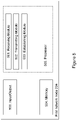
- the first network node 204 may be configured according to an arrangement depicted in Figure 5 . As previously mentioned, the first network node 204 and the second network node 206 are operating in the wireless communications network 200.
- the first network node 204 comprises an input and output interface 500 configured to communicate, with one or more network nodes, e.g. the second network node 206, the one or more further second network nodes 206', and/or the third network node 208, operating in the wireless communications network 100.
- the input and output interface 500 may comprise a wireless receiver (not shown) and a wireless transmitter (not shown).
- the first network node 204 is configured to receive, e.g. by means of a receiving module 501 configured to receive, a transmission from the communications device 210 or from one or more network nodes, e.g. the second network node 206, the one or more further second network nodes 206', and/or the third network node 208, operating in the wireless communications network 200.
- the receiving module 501 may be implemented by or arranged in communication with a processor 505 of the first network node 204.
- the processor 505 will be described in more detail below.
- the first network node 204 is configured to receive a random access request from the communications device 210 operating in the wireless communications network 200.
- the first network node 204 is configured to receive, from the third network node 208, a request to store the received random access request and the first information.
- the first network node 204 may receive, from the second network node 206 or the third network node 208, a request to establish the neighbour relation with the second network node 206 based on the neighbour node determination performed based on the first information by the third network node 208.
- the first network node 204 is configured to transmit, e.g. by means of a transmitting module 502 configured to transmit, a transmission to the communications device 210 or to one or more network nodes, e.g. the second network node 206, the one or more further second network nodes 206', and/or the third network node 208, operating in the wireless communications network 200.
- the transmitting module 402 may be implemented by or arranged in communication with the processor 505 of the first network node 204.
- the first network node 204 is configured to transmit, to the third network node 208 operating in the wireless communications network 200, a first information.
- the first information relates to an identity of a preamble comprised in the received random access request and to a first reception time of the random access request.
- the first network node 204 may transmit the first information when a signal strength of the received random access request is above a threshold value.
- the first network node 204 is configured to transmit, to the third network node 208, a request to configure the second network node 206 and/or one or more further second network nodes 206' to store the random access request when received by the second network node 206 or by the one or more further second network nodes 206' and to store a second information.
- the second information may relate to the identity of a preamble comprised in the received random access request and to a second reception time of the received random access request when received by the respective any one or more out of the second network node 206 and one or more further second network nodes 206'.
- the first network node 204 may be configured to transmit, to the communications device 210, a random access response in response to the received random access request.
- the first network node 204 is configured to transmit the random access response to the communications device 210 by being configured to transmit the random access response when the signal strength of the received random access request is above a threshold value; to transmit the random access response after reception of a plurality of random access request, and/or to transmit the random access response at randomly determined point of time.
- the first network node 204 is configured to establish, e.g. by means of an establishing module 503 configured to establish, a neighbour relation with the second network node 206 and possibly with one or more further second network nodes 206'.
- the establishing module 503 may be implemented by or arranged in communication with the processor 505 of the first network node 204.
- the first network node 204 is configured to establish a neighbour relation with the second network node 206 based on a neighbour node determination performed based on the first information by the third network node 208.
- the first network node 204 is configured to establish the neighbour relation with the second network node 206 by being configured to set up a communications link 212 with the second network node; and to update neighbour information with information relating to the second network node 206.
- the first network node 204 may be configured to establish beam relations.
- the first network node 204 may be configured to exchange and store one or more beam identifiers in a neighbour relation table.
- the first network node 204 may also comprise means for storing data.
- the first network node 204 comprises a memory 504 configured to store the data.
- the data may be processed or non-processed data and/or information relating thereto.
- the memory 504 may comprise one or more memory units.
- the memory 504 may be a computer data storage or a semiconductor memory such as a computer memory, a read-only memory, a volatile memory or a non-volatile memory.
- the memory is arranged to be used to store obtained information, data, configurations, schedulings, and applications etc. to perform the methods herein when being executed in the first network node 204.
- Embodiments herein for establishing a neighbour relation with the second network node 206 may be implemented through one or more processors, such as the processor 505 in the arrangement depicted in Figure 5 , together with computer program code for performing the functions and/or method actions of embodiments herein.
- the program code mentioned above may also be provided as a computer program product, for instance in the form of a data carrier carrying computer program code for performing the embodiments herein when being loaded into the first network node 204.
- One such carrier may be in the form of an electronic signal, an optical signal, a radio signal or a computer readable storage medium.
- the computer readable storage medium may be a CD ROM disc or a memory stick.
- the computer program code may furthermore be provided as program code stored on a server and downloaded to the first network node 204.
- the input/output interface 500, the receiving module 501, the transmitting module 502, and the establishing module 503 above may refer to a combination of analog and digital circuits, and/or one or more processors configured with software and/or firmware, e.g. stored in the memory 504, that when executed by the one or more processors such as the processors in the first network node 204 perform as described above.
- processors as well as the other digital hardware, may be included in a single Application-Specific Integrated Circuitry (ASIC), or several processors and various digital hardware may be distributed among several separate components, whether individually packaged or assembled into a System-on-a-Chip (SoC).
- ASIC Application-Specific Integrated Circuitry
- SoC System-on-a-Chip
- the first network node 204 and the second network node 206 are operating in the wireless communications network 200.
- the neighbour relation may be a node neighbour relation or a beam neighbour relation, wherein the node neighbour relation relates to a relation between neighbouring nodes and the beam neighbour relation relates to a relation between neighbouring beams.
- the methods comprise one or more of the following actions, some of which encompass the invention. It should be understood that the actions may be taken in any suitable order and that some actions may be combined. Actions that are optional are presented in dashed boxes in Figure 6 .
- the second network node 206 receives a random access request from the communications device 210 operating in the wireless communications network 200.
- This Action relates to Action 302 previously described.
- the second network node 206 may receive, from the third network node 208, a request to transmit to the third network node 208 a second information.
- the second information may relate to an identity of a preamble comprised in the received random access request and to a second reception time of the random access request.
- This Action relates to Action 307 previously described.
- the third network node 208 may request the second network node 206 to transmit an acknowledgement (ACK) if the second network node 206 has received the random access reception with the preamble preamble_A at a point of time T, and a negative acknowledgement (NACK) if the second network node 206 has not received the random access reception with the preamble preamble_A at a point of time T, respectively.
- ACK acknowledgement
- NACK negative acknowledgement
- the second information is an ACK or a NACK, or the second information comprises an ACK or a NACK.
- the second information may comprise an acknowledgement (ACK) by means of which the second network node 206 acknowledges reception of the random access reception with the preamble preamble_A at the point of time T.
- ACK acknowledgement
- the second information e.g. the ACK, relates to the identity of the preamble preamble_A and to the second reception time, e.g. to the point of time T.
- the second network node 206 transmits, to the third network node 208 operating in the wireless communications network 200, the second information.
- the second information relates to an identity of a preamble comprised in the received random access request and to a second reception time of the random access request.
- the second information may be an ACK or a NACK or it may comprise an ACK or a NACK.
- the second network node 206 transmits the second information to the third network node 208 when a signal strength of the received random access request is above a threshold value.
- This Action relates to Action 308 previously described.
- the second network node 206 receives, from the third network node 208, a request to store the received random access request and the second information.
- the second network node 206 may store information relating to one or more received random access requests, one or more received preambles and/or one or more reception times.
- This Action relates to Actions 301 and 303 previously described.
- the second network node 206 receives, from the first network node 204 or the third network node 208, a request to establish the neighbour relation with the first network node 204 based on the neighbour node determination performed based on the second information by the third network node 208.
- This Action relates to Action 309 previously described.
- the second network node 206 establishes a neighbour relation with the first network node 204 based on the neighbour node determination performed based on the second information by the third network node 208.
- the second network node 206 established the neighbour relation with the first network node 204 by possibly setting up a communications link 212 with the first network node 204 and updating neighbour information with information relating to the first network node 204.
- the second network node 206 may set up the communication link 212 if a communication link is not already set up with the first network node 204.
- the second network node 206 may also establish beam neighbour relations.
- a beam relation is meant that the beam identifiers of the beams corresponding to the RA direction of the received preamble are exchanged and stored in a neighbour relation table.
- the second network node 206 may exchange and store one or more beam identifiers in a neighbour relation table.
- This Action relates to Action 310 previously described.
- the second network node 206 may transmit, to the communications device 210, a random access response in response to the received random access request.
- the second network node 206 may transmit the random access response to the communications device 210 by transmitting the random access response when the signal strength of the received random access request is above a threshold value, by transmitting the random access response after reception of a plurality of random access requests, and/or by transmitting the random access response at a randomly determined point of time.
- This Action relates to Action 305 previously described.
- the second network node 206 may be configured according to an arrangement depicted in Figure 7 . As previously mentioned, the first network node 204 and the second network node 206 are operating in the wireless communications network 200.
- the second network node 206 comprises an input and output interface 700 configured to communicate, with one or more network nodes, e.g. the first network node 204, the one or more further second network nodes 206', and/or the third network node 208, operating in the wireless communications network 100.
- the input and output interface 700 may comprise a wireless receiver (not shown) and a wireless transmitter (not shown).
- the second network node 206 is configured to receive, e.g. by means of a receiving module 701 configured to receive, a transmission from the communications device 210 or from one or more network nodes, e.g. the first network node 204, the one or more further second network nodes 206', and/or the third network node 208, operating in the wireless communications network 200.
- the receiving module 701 may be implemented by or arranged in communication with a processor 705 of the second network node 206.
- the processor 705 will be described in more detail below.
- the second network node 206 is configured to receive a random access request from the communications device 210 operating in the wireless communications network 200.
- the second network node 206 is configured to receive, from the third network node 208, a request to store the received random access request and the second information.
- the second network node 206 may be configured to store information relating to one or more received random access requests, one or more received preambles, and/or one or more reception times.
- the second network node 206 may receive, from the third network node 208, a request to transmit the second information to the third network node 208.
- the second network node 206 may receive, from the first network node 204 or the third network node 208, a request to establish the neighbour relation with the first network node 204 based on the neighbour node determination performed by the third network node 208 based on the second information.
- the second network node 206 is configured to transmit, e.g. by means of a transmitting module 702 configured to transmit, a transmission to the communications device 210 or to one or more network nodes, e.g. the first network node 204, the one or more further second network nodes 206', and/or the third network node 208, operating in the wireless communications network 200.
- the transmitting module 702 may be implemented by or arranged in communication with the processor 705 of the second network node 206.
- the second network node 206 is configured to transmit, to the third network node 208 operating in the wireless communications network 200, the second information.
- the second information relates to an identity of a preamble comprised in the received random access request and to a second reception time of the random access request.
- the second reception time is the point of time the second network node 206 received the preamble.
- the second network node 206 may transmit the second information when a signal strength of the received random access request is above a threshold value.
- the second network node 206 may be configured to transmit, to the communications device 210, a random access response in response to the received random access request.
- the second network node 206 is configured to transmit the random access response to the communications device 210 by being configured to transmit the random access response when the signal strength of the received random access request is above a threshold value, to transmit the random access response after reception of a plurality of random access request, and/or to transmit the random access response at randomly determined point of time.
- the second network node 206 is configured to establish, e.g. by means of an establishing module 703 configured to establish, a neighbour relation with the first network node 204 and possibly with one or more further second network nodes 206'.
- the establishing module 703 may be implemented by or arranged in communication with the processor 705 of the second network node 206.
- the second network node 206 is configured to establish a neighbour relation with the first network node 204 based on a neighbour node determination performed by the third network node 208 based on the second information.
- the second network node 206 is configured to establish the neighbour relation with the first network node 204 by being configured to set up a communications link 212 with the first network node 204 and to update neighbour information with information relating to the first network node 204.
- the second network node 206 may be configured to establish beam relations.
- the second network node 206 may be configured to exchange and store one or more beam identifiers in a neighbour relation table.
- the second network node 206 may also comprise means for storing data.
- the second network node 206 comprises a memory 704 configured to store the data.
- the data may be processed or non-processed data and/or information relating thereto.
- the memory 704 may comprise one or more memory units.
- the memory 704 may be a computer data storage or a semiconductor memory such as a computer memory, a read-only memory, a volatile memory or a non-volatile memory.
- the memory is arranged to be used to store obtained information, data, configurations, schedulings, and applications etc. to perform the methods herein when being executed in the second network node 206.
- Embodiments herein for establishing a neighbour relation with the first network node 204 may be implemented through one or more processors, such as the processor 705 in the arrangement depicted in Figure 7 , together with computer program code for performing the functions and/or method actions of embodiments herein.
- the program code mentioned above may also be provided as a computer program product, for instance in the form of a data carrier carrying computer program code for performing the embodiments herein when being loaded into the second network node 206.
- One such carrier may be in the form of an electronic signal, an optical signal, a radio signal or a computer readable storage medium.
- the computer readable storage medium may be a CD ROM disc or a memory stick.
- the computer program code may furthermore be provided as program code stored on a server and downloaded to the second network node 206.
- the input/output interface 700, the receiving module 701, the transmitting module 702, and the establishing module 703 above may refer to a combination of analog and digital circuits, and/or one or more processors configured with software and/or firmware, e.g. stored in the memory 704, that when executed by the one or more processors such as the processors in the second network node 206 perform as described above.
- processors as well as the other digital hardware, may be included in a single Application-Specific Integrated Circuitry (ASIC), or several processors and various digital hardware may be distributed among several separate components, whether individually packaged or assembled into a System-on-a-Chip (SoC).
- ASIC Application-Specific Integrated Circuitry
- SoC System-on-a-Chip
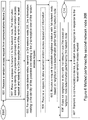
- the third network node 208 Examples of methods performed by the third network node 208 for requesting establishment of a neighbour relation between the first network node 204 and the second network node 206 will now be described with reference to the flowchart depicted in Figure 8 .
- the first network node 204, the second network node 206 and the third network node 208 are operating in the wireless communications network 200.
- the neighbour relation may be a node neighbour relation or a beam neighbour relation, wherein the node neighbour relation relates to a relation between neighbouring nodes and the beam neighbour relation relates to a relation between neighbouring beams.
- the methods comprise one or more of the following actions, some of which encompass the invention. It should be understood that the actions may be taken in any suitable order and that some actions may be combined. Actions that are optional are presented in dashed boxes in Figure 8 .
- the third network node 208 transmits, to the second network node 206, a request to transmit to the third network node 208 the second information.
- the third network node 208 may be triggered by the first network node 204 to transmit the request to the second network node 206.
- This Action relates to Actions 307 and 602 previously described.
- the third network node 208 may request the second network node 206 to transmit an ACK if the second network node 206 has received the random access reception with the preamble preamble_A at a point of time T, and a NACK if the second network node 206 has not received the random access reception with the preamble preamble_A at a point of time T, respectively.
- the third network node 208 receives, from the first network node 204, a first information, which first information relates to an identity of a preamble comprised in a random access request received by the first network node 204 and to a first reception time of the received random access request.
- This Action relates to Actions 304, 404 previously described.
- the third network node 208 receives, from the second network node 206, a second information, which second information relates to the identity of the preamble comprised in a random access request a random access request received by the second network node 206 and to a second reception time of the received random access request.
- the second information may be an ACK or a NACK or it may comprise an ACK or a NACK.
- the second information is an ACK or a NACK, or the second information comprises an ACK or a NACK.
- the second information may comprise an ACK by means of which the second network node 206 acknowledges reception of the random access reception with the preamble preamble_A at the point of time T.
- the second information e.g. the ACK, relates to the identity of the preamble preamble_A and to the second reception time, e.g. to the point of time T.
- the third network node 208 transmits, to the first network node 204 and/or the second network node 206, a request to store the received random access request and information relating to the identity of the preamble comprised in the received random access request and relating to the reception time of the random access request.
- the third network node 208 may transmit the request to store the received random access request and information in response to an indication received from a network node, e.g. the first network node 204 and/or the second network node 206, that the network node needs other network nodes, for example network nodes geographically close, to store the received random access request and information, e.g. the preamble and time information.
- the third network node 208 may transmit the request to store the received random access request and information to the first network node 204 in response to an indication received from the second network node 206, which indication indicates that the second network node 206 needs one or more other network nodes, e.g. the first network node 204, to store the received random access request and information, and vice versa.
- This Action relates to Actions 301, 403 and 602 previously described.
- the third network node 208 determines the first network node 204 and the second network node 206 as being neighbour nodes.
- the third network node 208 determines the first network node 204 and the second network node 206 as being neighbour nodes by determining that the first and second information relate to the same identity of the preamble, and by determining that the first and second reception times are equal or almost equal.
- “almost equal reception times” is meant that the difference between the first and second reception times is within a desired threshold value.
- the first and second reception times should be so close to each other that the difference in time corresponds to the different distances of the propagation paths from the communications device 210 to the first network node 204 and to the one or more second network nodes 206, 206' respectively.
- This Action relates to Action 309 previously described.
- the third network node 208 requests the first network node 204 and/or the second network node 206 to establish a neighbour relation.
- This Action relates to Action 309 previously described.
- the third network node 208 may be configured according to an arrangement depicted in Figure 8 . As previously mentioned, the first network node 204, the second network node 206 and the third network node 208 are operating in the wireless communications network 200.
- the third network node 208 comprises an input and output interface 900 configured to communicate, with one or more network nodes, e.g. the first network node 204, the second network node 206, the one or more further second network nodes 206', and/or with the communications device 210, operating in the wireless communications network 100.
- the input and output interface 900 may comprise a wireless receiver (not shown) and a wireless transmitter (not shown).
- the third network node 208 is configured to receive, e.g. by means of a receiving module 901 configured to receive, a transmission from the communications device 210 or from one or more network nodes, e.g. the first network node 204, the second network node 206 and/or the one or more further second network nodes 206' operating in the wireless communications network 200.
- the receiving module 901 may be implemented by or arranged in communication with a processor 906 of the third network node 208.
- the processor 906 will be described in more detail below.
- the third network node 208 is configured to receive, from the first network node 204, a first information.
- the first information relates to an identity of a preamble comprised in a random access request received by the first network node 204 and to a first reception time of the received random access request.
- the third network node 208 is configured to receive, from the second network node 206, a second information.
- the second information relates to the identity of the preamble comprised in a random access request received by the second network node 206 and to a second reception time of the received random access request.
- the third network node 208 is configured to transmit, e.g. by means of a transmitting module 902 configured to transmit, a transmission to the communications device 210 or to one or more network nodes, e.g. the first network node 204, the second network node 206 and/or the one or more further second network nodes 206' operating in the wireless communications network 200.
- the transmitting module 902 may be implemented by or arranged in communication with the processor 906 of the third network node 208.
- the third network node 208 is configured to transmit, to the first network node 204 and/or the second network node 206, a request to store the received random access request and information relating to the identity of the preamble comprised in the received random access request and relating to the reception time of the random access request.
- the third network node 208 may be configured to transmit, to the second network node 206, a request to transmit to the third network node 208 the second information.
- the third network node 208 is configured to determine, e.g. by means of a determining module 903 configured to determine, two or more network nodes, e.g. two or more of the first network node 204, the second network node 206 and/or the one or more further second network nodes 206', as being neighbour nodes.
- the determining module 903 may be implemented by or arranged in communication with the processor 906 of the third network node 208.
- the third network node 208 is configured to determine the first network node 204 and the second network node 206 as being neighbour nodes. In some embodiments, the third network node 208 is configured to determine the first network node 204 and the second network node 206 as being neighbour nodes by being configured to determine that the first and second information relate to the same identity of the preamble; and determine that the first and second reception times are equal or almost equal.
- the third network node 208 is configured to request, e.g. by means of a requesting module 904 configured to request, establishment of a neighbour relation.
- the requesting module 904 may be implemented by or arranged in communication with the processor 906 of the third network node 208.
- the third network node 208 is configured to request the first network node 204 and/or the second network node 206 to establish a neighbour relation.
- the third network node 208 may also comprise means for storing data.
- the third network node 208 comprises a memory 905 configured to store the data.
- the data may be processed or non-processed data and/or information relating thereto.
- the memory 905 may comprise one or more memory units.
- the memory 905 may be a computer data storage or a semiconductor memory such as a computer memory, a read-only memory, a volatile memory or a non-volatile memory.
- the memory is arranged to be used to store obtained information, data, configurations, schedulings, and applications etc. to perform the methods herein when being executed in the third network node 208.
- Embodiments herein for establishing a neighbour relation between the first network node 204 and the second network node 206 may be implemented through one or more processors, such as the processor 906 in the arrangement depicted in Figure 9 , together with computer program code for performing the functions and/or method actions of embodiments herein.
- the program code mentioned above may also be provided as a computer program product, for instance in the form of a data carrier carrying computer program code for performing the embodiments herein when being loaded into the third network node 208.
- One such carrier may be in the form of an electronic signal, an optical signal, a radio signal or a computer readable storage medium.
- the computer readable storage medium may be a CD ROM disc or a memory stick.
- the computer program code may furthermore be provided as program code stored on a server and downloaded to the third network node 208.
- the input/output interface 900, the receiving module 901, the transmitting module 902, the determining module 904 and the requesting module 904 above may refer to a combination of analog and digital circuits, and/or one or more processors configured with software and/or firmware, e.g. stored in the memory 905, that when executed by the one or more processors such as the processors in the third network node 208 perform as described above.
- processors as well as the other digital hardware, may be included in a single Application-Specific Integrated Circuitry (ASIC), or several processors and various digital hardware may be distributed among several separate components, whether individually packaged or assembled into a System-on-a-Chip (SoC).
- ASIC Application-Specific Integrated Circuitry
- SoC System-on-a-Chip
- other network nodes that heard the RA request but communicated with the second network node 206 to send the single RAR message will also respond to the random access audibility request from the third network node 208, cf. Actions 307 and 801. Such embodiments will allow the establishment of neighbor relation dynamically with more than one neighbor network node.
- the first network node 204 refrains from the transmission of the random access response only when the received quality on the Random Access Channel (RACH) is below certain threshold. Such embodiments come handy when the first network node 204 is covering a previously existing coverage hole.
- RACH Random Access Channel
- the first network node 204 will wait for at least multiple RACH attempts before sending the RAR message in order to make sure that there is no other network node, e.g. the second network node 206, that could transmit the RAR to the communications device, e.g. to the communications device 210.
- the first network node 204 follows the mentioned procedure only probabilistically. This will enable the procedure to be used in the green-field scenario wherein the first network node 204 randomly, with a certain probability distribution according to the received quality of the RA request from the communications device 210, sends the RAR.
- the third network node 208 pre-configures all the network nodes, e.g. the second and one or more further second network nodes 206, 206', to always store and report the RA preamble used by the communications device 210 to access the wireless communications network 200.
- Actions 307 and 308 may be unnecessary as the third network node 208 already may know the network nodes hearing the corresponding RA attempt using a certain preamble.
- the process is initiated by the first network node 204 sending a request to the third network node 208 to request from other nodes, e.g. from the second or one or more further second network nodes 206, 206', to store the received random access preambles and corresponding time stamps of reception.
Landscapes
- Engineering & Computer Science (AREA)
- Computer Networks & Wireless Communication (AREA)
- Signal Processing (AREA)
- Mobile Radio Communication Systems (AREA)
Claims (18)
- Verfahren, das von einem ersten Netzwerkknoten (204) zum Aufbau einer Nachbarbeziehung mit einem zweiten Netzwerkknoten (206) durchgeführt wird, wobei der erste Netzwerkknoten (204) und der zweite Netzwerkknoten (206) in einem drahtlosen Kommunikationsnetzwerk (200) betrieben werden, wobei sich die Nachbarbeziehung auf eine Verbindung zwischen zwei benachbarten Knoten bezieht, die sich innerhalb einer Funkabdeckung zueinander befinden; und wobei das Verfahren Folgendes umfasst:- Empfangen (401) einer Direktzugriffsanforderung von einer Kommunikationsvorrichtung (210), die in dem drahtlosen Kommunikationsnetzwerk (200) arbeitet;- Übertragen (402) einer ersten Information an einen dritten Netzwerkknoten (208), der in dem drahtlosen Kommunikationsnetzwerk (200) arbeitet, zur Nachbarknotenbestimmung, wobei sich die erste Information auf eine Identität einer Präambel, die in der empfangenen Direktzugriffsanforderung enthalten ist, und auf eine erste Empfangszeit der Direktzugriffsanforderung bezieht, wobei das Übertragen (402) der ersten Information an den dritten Netzwerkknoten (208) Folgendes umfasst:- Übertragen der ersten Information, wenn eine Signalstärke der empfangenen Direktzugriffsanforderung über einem Schwellenwert liegt;- Übertragen (404) einer Anforderung an den dritten Netzwerkknoten (208), den zweiten Netzwerkknoten (206) dafür zu konfigurieren, die Direktzugriffsanforderung zu speichern, wenn sie von dem zweiten Netzwerkknoten (206) empfangen wird, und eine zweite Information zu speichern, wobei sich die zweite Information auf die Identität einer in der empfangenen Direktzugriffsanforderung enthaltenen Präambel und auf eine zweite Empfangszeit der empfangenen Direktzugriffsanforderung bezieht, wenn sie von dem zweiten Netzwerkknoten (206) empfangen wird; und- Herstellen (406) einer Nachbarbeziehung mit dem zweiten Netzwerkknoten (206) basierend auf einer durchgeführten Nachbarknotenbestimmung, basierend auf der ersten Information und der zweiten Information, die von dem ersten Netzwerkknoten (204) bzw. dem zweiten Netzwerkknoten (206) durch den dritten Netzwerkknoten (208) empfangen wurden.
- Verfahren nach Anspruch 1, das ferner Folgendes umfasst:- Empfangen (403) einer Anforderung zum Speichern der empfangenen Direktzugriffsanforderung und der ersten Informationen von dem dritten Netzwerkknoten (208).
- Verfahren nach Anspruch 1 oder 2, das ferner Folgendes umfasst:- Übertragen (404) einer Anforderung an den dritten Netzwerkknoten (208), einen oder mehrere weitere zweite Netzwerkknoten (206') dafür zu konfigurieren, die Direktzugriffsanforderung zu speichern, wenn sie von dem einen oder den mehreren zweiten Netzwerkknoten (206') empfangen wird, und eine zweite Information zu speichern, wobei sich die zweite Information auf die Identität einer in der empfangenen Direktzugriffsanforderung enthaltenen Präambel und auf eine zweite Empfangszeit der empfangenen Direktzugriffsanforderung bezieht, wenn sie von dem jeweiligen des einen oder der mehreren weiteren zweiten Netzwerkknoten (206') empfangen wird.
- Verfahren nach einem der Ansprüche 1 bis 3, das ferner Folgendes umfasst:- Empfangen (405), von dem zweiten Netzwerkknoten (206) oder dem dritten Netzwerkknoten (208), einer Anforderung zum Herstellen der Nachbarbeziehung mit dem zweiten Netzwerkknoten (206) basierend auf der Nachbarknotenbestimmung, die basierend auf der ersten Information durch den dritten Netzwerkknoten (208) durchgeführt wird.
- Verfahren nach einem der Ansprüche 1 bis 4, das ferner Folgendes umfasst:- Übertragen (407) einer Direktzugriffsantwort an die Kommunikationsvorrichtung (210) als Antwort auf die empfangene Direktzugriffsanforderung, wobei das Übertragen (407) der Direktzugriffsantwort eines der Folgenden umfasst:- Übertragen der Direktzugriffsantwort an die Kommunikationsvorrichtung (210), wenn die Signalstärke der empfangenen Direktzugriffsanforderung über einem Schwellenwert liegt,- Übertragen der Direktzugriffsantwort an die Kommunikationsvorrichtung (210) nach dem Empfang einer Vielzahl von Direktzugriffsanforderungen, und- Übertragen der Direktzugriffsantwort an die Kommunikationsvorrichtung (210) zu einem zufällig bestimmten Zeitpunkt.
- Verfahren nach einem der Ansprüche 1 bis 5, wobei das Herstellen (406) der Nachbarbeziehung mit dem zweiten Netzwerkknoten (206) Folgendes umfasst:Möglicherweise Aufbauen einer Kommunikationsverbindung (212) mit dem zweiten Netzwerkknoten (206); undAktualisieren von Nachbarinformationen mit Informationen, die sich auf den zweiten Netzwerkknoten (206) beziehen.
- Erster Netzwerkknoten (204) zum Aufbau einer Nachbarbeziehung mit einem zweiten Netzwerkknoten (206), wobei der erste Netzwerkknoten (204) und der zweite Netzwerkknoten (206) in einem drahtlosen Kommunikationsnetzwerk (200) betrieben werden, wobei sich die Nachbarbeziehung auf eine Verbindung zwischen zwei benachbarten Knoten bezieht, die sich innerhalb einer Funkabdeckung zueinander befinden; und wobei der erste Netzwerkknoten (204) für Folgendes konfiguriert ist:- Empfangen einer Direktzugriffsanforderung von einer Kommunikationsvorrichtung (210), die in dem drahtlosen Kommunikationsnetzwerk (200) arbeitet;- Übertragen einer ersten Information an einen dritten Netzwerkknoten (208), der in dem drahtlosen Kommunikationsnetzwerk (200) arbeitet, zur Nachbarknotenbestimmung, wobei sich die erste Information auf eine Identität einer Präambel, die in der empfangenen Direktzugriffsanforderung enthalten ist, und auf eine erste Empfangszeit der Direktzugriffsanforderung bezieht, wobei der erste Netzwerkknoten (204) dafür konfiguriert ist, die erste Information an den dritten Netzwerkknoten (208) zu übertragen, indem er für Folgendes konfiguriert ist:- Übertragen der ersten Information, wenn eine Signalstärke der empfangenen Direktzugriffsanforderung über einem Schwellenwert liegt;- Übertragen einer Anforderung zu dem dritten Netzwerkknoten (208), den zweiten Netzwerkknoten (206) so zu konfigurieren, dass er die Zufallszugriffsanforderung speichert, wenn sie von dem zweiten Netzwerkknoten (206) empfangen wird, und eine zweite Information zu speichern, wobei sich die zweite Information auf die Identität einer Präambel, die in der empfangenen Direktzugriffsanforderung enthalten ist, und auf eine zweite Empfangszeit der empfangenen Direktzugriffsanforderung bezieht, wenn sie von dem zweiten Netzwerkknoten (206) empfangen wird; und- Herstellen einer Nachbarbeziehung mit dem zweiten Netzwerkknoten (206) basierend auf einer Nachbarknotenbestimmung, die basierend auf der ersten Information und der zweiten Information, die jeweils von dem ersten Netzwerkknoten (204) und dem zweiten Netzwerkknoten (206) empfangen wurden, durch den dritten Netzwerkknoten (208) durchgeführt wird.
- Erster Netzwerkknoten (204) nach Anspruch 7, der ferner für Folgendes konfiguriert ist:- Empfangen einer Anforderung zum Speichern der empfangenen Direktzugriffsanforderung und der ersten Informationen von dem dritten Netzwerkknoten (208).
- Erster Netzwerkknoten (204) nach Anspruch 7 oder 8, der ferner für Folgendes konfiguriert ist:- Übertragen einer Anforderung an den dritten Netzwerkknoten (208), einen oder mehrere weitere zweite Netzwerkknoten (206') dafür zu konfigurieren, die Direktzugriffsanforderung zu speichern, wenn sie von dem einen oder den mehreren weiteren zweiten Netzwerkknoten (206') empfangen wird, und eine zweite Information zu speichern, wobei sich die zweite Information auf die Identität einer Präambel, die in der empfangenen Direktzugriffsanforderung enthalten ist, und auf eine zweite Empfangszeit der empfangenen Direktzugriffsanforderung bezieht, wenn sie von dem jeweiligen des einen oder der mehreren weiteren zweiten Netzwerkknoten (206') empfangen wird.
- Erster Netzwerkknoten (204) nach einem der Ansprüche 7 bis 9, der ferner für Folgendes konfiguriert ist:- Empfangen, von dem zweiten Netzwerkknoten (206) oder dem dritten Netzwerkknoten (208), einer Anforderung zum Herstellen der Nachbarbeziehung mit dem zweiten Netzwerkknoten (206) basierend auf der Nachbarknotenbestimmung, die basierend auf der ersten Information durch den dritten Netzwerkknoten (208) durchgeführt wurde.
- Erster Netzwerkknoten (204) nach einem der Ansprüche 7 bis 10, der ferner für Folgendes konfiguriert ist:- Übertragen einer Direktzugriffsantwort an die Kommunikationsvorrichtung (210) als Antwort auf die empfangene Direktzugriffsanforderung, wobei der erste Netzwerkknoten (204) dafür konfiguriert ist, die Direktzugriffsantwort gemäß einem der Folgenden zu übertragen:- Übertragen der Direktzugriffsantwort an die Kommunikationsvorrichtung (210), wenn die Signalstärke der empfangenen Direktzugriffsanforderung über einem Schwellenwert liegt,- Übertragen der Direktzugriffsantwort an die Kommunikationsvorrichtung (210) nach dem Empfang einer Vielzahl von Direktzugriffsanforderungen, und- Übertragen der Direktzugriffsantwort an die Kommunikationsvorrichtung (210) zu einem zufällig bestimmten Zeitpunkt.
- Erster Netzwerkknoten (204) nach einem der Ansprüche 7 bis 11, wobei der erste Netzwerkknoten (204) dafür konfiguriert ist, die Nachbarbeziehung mit dem zweiten Netzwerkknoten (206) herzustellen, indem er für Folgendes konfiguriert ist:- Möglicherweise Aufbauen einer Kommunikationsverbindung (212) mit dem zweiten Netzwerkknoten (206); und- Aktualisieren von Nachbarinformationen mit Informationen, die sich auf den zweiten Netzwerkknoten (206) beziehen.
- Verfahren, das von einem zweiten Netzwerkknoten (206) zum Aufbau einer Nachbarbeziehung mit einem ersten Netzwerkknoten (204) durchgeführt wird, wobei der erste Netzwerkknoten (204) und der zweite Netzwerkknoten (206) in einem drahtlosen Kommunikationsnetzwerk (200) betrieben werden, wobei sich die Nachbarbeziehung auf eine Verbindung zwischen zwei benachbarten Knoten bezieht, die sich innerhalb einer Funkabdeckung zueinander befinden; und wobei das Verfahren Folgendes umfasst:- Empfangen (601) einer Direktzugriffsanforderung von einer Kommunikationsvorrichtung (210), die in dem drahtlosen Kommunikationsnetzwerk (200) arbeitet;- Empfangen (602), von einem dritten Netzwerkknoten (208), der in dem drahtlosen Kommunikationsnetzwerk (200) arbeitet, einer Anforderung zum Übertragen einer zweiten Information an den dritten Netzwerkknoten (208);- Übertragen (603) der zweiten Information an den dritten Netzwerkknoten (208) zur Bestimmung des Nachbarknotens, wobei sich die zweite Information auf eine Identität einer Präambel, die in der empfangenen Direktzugriffsanforderung enthalten ist, und auf eine zweite Empfangszeit der Direktzugriffsanforderung bezieht, wobei der zweite Netzwerkknoten (206) dafür konfiguriert ist, die zweite Information an den dritten Netzwerkknoten (208) für Folgendes zu übertragen: wenn eine Signalstärke der empfangenen Direktzugriffsanforderung über einem Schwellenwert liegt;- Empfangen (604) einer Anforderung zum Speichern der empfangenen Direktzugriffsanforderung und der zweiten Informationen von dem dritten Netzwerkknoten (208); und- Herstellen (606) einer Nachbarbeziehung mit dem ersten Netzwerkknoten (204) basierend auf einer Nachbarknotenbestimmung, die basierend auf der zweiten Information und der ersten Information, die jeweils von dem zweiten Netzwerkknoten (206) und dem ersten Netzwerkknoten (204) durch den dritten Netzwerkknoten (208) durchgeführt wird.
- Verfahren nach Anspruch 13, das ferner Folgendes umfasst:- Empfangen (605), von dem ersten Netzwerkknoten (204) oder dem dritten Netzwerkknoten (208), einer Anforderung zum Herstellen der Nachbarbeziehung mit dem ersten Netzwerkknoten (204) basierend auf der Nachbarknotenbestimmung, die durch den dritten Netzwerkknoten (208) durchgeführt wird.
- Zweiter Netzwerkknoten (206) zum Aufbau einer Nachbarbeziehung mit einem ersten Netzwerkknoten (204), wobei der erste Netzwerkknoten (204) und der zweite Netzwerkknoten (206) in einem drahtlosen Kommunikationsnetzwerk (200) betrieben werden, wobei sich die Nachbarbeziehung auf eine Verbindung zwischen zwei benachbarten Knoten bezieht, die sich innerhalb einer Funkabdeckung zueinander befinden; und wobei der zweite Netzwerkknoten (206) für Folgendes konfiguriert ist:- Empfangen einer Direktzugriffsanforderung von einer Kommunikationsvorrichtung (210), die in dem drahtlosen Kommunikationsnetzwerk (200) arbeitet;- Empfangen, von einem dritten Netzwerkknoten (208), der in dem drahtlosen Kommunikationsnetzwerk (200) arbeitet, einer Anforderung zum Übertragen einer zweiten Information an den dritten Netzwerkknoten (208);- Übertragen der zweiten Information an den dritten Netzwerkknoten (208) zur Bestimmung des Nachbarknotens, wobei sich die zweite Information auf eine Identität einer Präambel, die in der empfangenen Direktzugriffsanforderung enthalten ist, und auf eine zweite Empfangszeit der Direktzugriffsanforderung bezieht, wobei der zweite Netzwerkknoten (206) dafür konfiguriert ist, die zweite Information an den dritten Netzwerkknoten (208) zu übertragen, wenn eine Signalstärke der empfangenen Direktzugriffsanforderung über einem Schwellenwert liegt;- Empfangen einer Anforderung zum Speichern der empfangenen Direktzugriffsanforderung und der zweiten Informationen von dem dritten Netzwerkknoten (208); und- Herstellen einer Nachbarbeziehung mit dem ersten Netzwerkknoten (204) basierend auf einer Nachbarknotenbestimmung, die basierend auf der zweiten Information und einer ersten Information, die von dem zweiten Netzwerkknoten (206) bzw. dem ersten Netzwerkknoten (204) empfangen wurde, von dem dritten Netzwerkknoten (208) durchgeführt wird.
- Zweiter Netzwerkknoten (206) nach Anspruch 15, der ferner für Folgendes konfiguriert ist:- Empfangen, von dem ersten Netzwerkknoten (204) oder dem dritten Netzwerkknoten (208), einer Anforderung zum Herstellen der Nachbarbeziehung mit dem ersten Netzwerkknoten (204) basierend auf der Nachbarknotenbestimmung, die durch den dritten Netzwerkknoten (208) durchgeführt wird.
- Verfahren, das von einem dritten Netzwerkknoten (208) durchgeführt wird, um die Einrichtung einer Nachbarbeziehung zwischen einem ersten Netzwerkknoten (204) und einem zweiten Netzwerkknoten (206) anzufordern, wobei der erste Netzwerkknoten (204) und der zweite Netzwerkknoten (206) in einem drahtlosen Kommunikationsnetzwerk (200) betrieben werden, wobei sich die Nachbarbeziehung auf eine Verbindung zwischen zwei benachbarten Knoten bezieht, die sich innerhalb einer Funkabdeckung zueinander befinden; und wobei das Verfahren Folgendes umfasst:- Empfangen (802), von dem ersten Netzwerkknoten (204), einer ersten Information, wobei sich die erste Information auf eine Identität einer Präambel, die in einer von dem ersten Netzwerkknoten (204) empfangenen Direktzugriffsanforderung enthalten ist, und auf eine erste Empfangszeit der empfangenen Direktzugriffsanforderung bezieht;- Empfangen einer Anforderung von dem ersten Netzwerkknoten (204), den zweiten Netzwerkknoten (206) dafür zu konfigurieren, die Direktzugriffsanforderung zu speichern, wenn sie von dem zweiten Netzwerkknoten (206) empfangen wird, und eine zweite Information zu speichern;- Empfangen (803), von dem zweiten Netzwerkknoten (206), der zweiten Information, wobei sich die zweite Information auf die Identität der Präambel, die in einer von dem zweiten Netzwerkknoten (206) empfangenen Direktzugriffsanforderung enthalten ist, und auf eine zweite Empfangszeit der empfangenen Direktzugriffsanforderung bezieht;- Übertragen (804) an den zweiten Netzwerkknoten (206) einer Anforderung zum Speichern der empfangenen Direktzugriffsanforderung und einer Information, die sich auf die Identität der Präambel bezieht, die in der empfangenen Direktzugriffsanforderung enthalten sind und sich auf die Empfangszeit der Direktzugriffsanforderung beziehen;- Bestimmen (805) des ersten Netzwerkknotens (204) und des zweiten Netzwerkknotens (206) als Nachbarknoten durch:- Bestimmen, dass sich die erste und die zweite Information auf die gleiche Identität der Präambel beziehen; und- Bestimmen, dass die erste und die zweite Empfangszeit gleich oder fast gleich sind; und- Auffordern (806) des ersten Netzwerkknotens (204) und des zweiten Netzwerkknotens (206), eine Nachbarbeziehung herzustellen.
- Dritter Netzwerkknoten (208) zum Anfordern des Aufbaus einer Nachbarbeziehung zwischen einem ersten Netzwerkknoten (204) und einem zweiten Netzwerkknoten (206), wobei der erste Netzwerkknoten (204) und der zweite Netzwerkknoten (206) in einem drahtlosen Kommunikationsnetzwerk (200) betrieben werden, wobei sich die Nachbarbeziehung auf eine Verbindung zwischen zwei benachbarten Knoten bezieht, die sich innerhalb einer Funkabdeckung zueinander befinden; und wobei der dritte Netzwerkknoten (208) für Folgendes konfiguriert ist:- Empfangen, von dem ersten Netzwerkknoten (204), einer ersten Information, wobei sich die erste Information auf eine Identität einer Präambel, die in einer von dem ersten Netzwerkknoten (204) empfangenen Direktzugriffsanforderung enthalten ist, und auf eine erste Empfangszeit der empfangenen Direktzugriffsanforderung bezieht;- Empfangen einer Anforderung von dem ersten Netzwerkknoten (204), den zweiten Netzwerkknoten (206) dafür zu konfigurieren, die Direktzugriffsanforderung zu speichern, wenn sie von dem zweiten Netzwerkknoten (206) empfangen wird, und eine zweite Information zu speichern;- Empfangen, von dem zweiten Netzwerkknoten (206), einer zweiten Information, wobei sich die zweite Information auf die Identität der Präambel, die in einer von dem zweiten Netzwerkknoten (206) empfangenen Direktzugriffsanforderung enthalten ist, und auf eine zweite Empfangszeit der empfangenen Direktzugriffsanforderung bezieht;- Übertragen an den zweiten Netzwerkknoten (206) einer Anforderung zum Speichern der empfangenen Direktzugriffsanforderung und einer Information, die sich auf die Identität der Präambel bezieht, die in der empfangenen Direktzugriffsanforderung enthalten sind und sich auf die Empfangszeit der Direktzugriffsanforderung beziehen;- Bestimmen des ersten Netzwerkknotens (204) und des zweiten Netzwerkknotens (206) als Nachbarknoten, indem sie für Folgendes konfiguriert sind:- Bestimmen, dass sich die erste und die zweite Information auf die gleiche Identität der Präambel beziehen; und- Bestimmen, dass die erste und die zweite Empfangszeit gleich oder fast gleich sind; und- Auffordern des ersten Netzwerkknotens (204) und des zweiten Netzwerkknotens (206), eine Nachbarbeziehung herzustellen.
Applications Claiming Priority (1)
| Application Number | Priority Date | Filing Date | Title |
|---|---|---|---|
| PCT/SE2016/051059 WO2018080362A1 (en) | 2016-10-28 | 2016-10-28 | Network nodes, and methods therein for establishment of a neighbour node relation |
Publications (3)
| Publication Number | Publication Date |
|---|---|
| EP3533256A1 EP3533256A1 (de) | 2019-09-04 |
| EP3533256A4 EP3533256A4 (de) | 2019-10-16 |
| EP3533256B1 true EP3533256B1 (de) | 2022-12-07 |
Family
ID=62025298
Family Applications (1)
| Application Number | Title | Priority Date | Filing Date |
|---|---|---|---|
| EP16919887.6A Active EP3533256B1 (de) | 2016-10-28 | 2016-10-28 | Netzwerkknoten und verfahren darin zum aufbau einer beziehung zwischen benachbarten knoten |
Country Status (4)
| Country | Link |
|---|---|
| US (1) | US10694543B2 (de) |
| EP (1) | EP3533256B1 (de) |
| CN (1) | CN109923895B (de) |
| WO (1) | WO2018080362A1 (de) |
Families Citing this family (5)
| Publication number | Priority date | Publication date | Assignee | Title |
|---|---|---|---|---|
| WO2018080361A1 (en) * | 2016-10-28 | 2018-05-03 | Telefonaktiebolaget Lm Ericsson (Publ) | A first network node, a second network node, a third network node, and methods therein for establishment of a neighbour relation |
| EP3533256B1 (de) | 2016-10-28 | 2022-12-07 | Telefonaktiebolaget LM Ericsson (publ) | Netzwerkknoten und verfahren darin zum aufbau einer beziehung zwischen benachbarten knoten |
| CN113615297B (zh) * | 2019-03-28 | 2024-02-20 | 中兴通讯股份有限公司 | 无线网络接入节点中随机接入信道配置的协同优化 |
| PL3821666T3 (pl) * | 2019-09-30 | 2024-05-13 | Nokia Technologies Oy | Dostęp swobodny w systemie komunikacyjnym |
| CN120390309A (zh) * | 2024-01-29 | 2025-07-29 | 华为技术有限公司 | 随机接入方法及随机接入装置 |
Family Cites Families (23)
| Publication number | Priority date | Publication date | Assignee | Title |
|---|---|---|---|---|
| CN100466844C (zh) * | 2006-07-19 | 2009-03-04 | 华为技术有限公司 | 漏配邻区的检测方法及其系统 |
| EP2151138A1 (de) * | 2007-04-30 | 2010-02-10 | InterDigital Technology Corporation | Zellenneuauswahl und weiterreichen mit multimedia broadcast/multicastdienst |
| KR100875477B1 (ko) * | 2007-12-29 | 2008-12-26 | (주)카이로넷 | Ofdm 시스템 및 상기 ofdm 시스템의 프리엠블 전력제어방법 |
| BRPI0908462B1 (pt) | 2008-02-04 | 2020-10-20 | Snaptrack, Inc. | sistema de comunicação móvel, dispositivo de estação base, dispositivo de estação móvel, e método de comunicação móvel |
| US8718635B2 (en) | 2008-04-22 | 2014-05-06 | Apple Inc. | Optimizing neighbor lists |
| EP2452535A1 (de) * | 2009-07-07 | 2012-05-16 | Telefonaktiebolaget LM Ericsson (publ) | Direktzugriffsverfahren mit zyklischer verschiebung eines demodulationsreferenzsignals |
| US8934412B2 (en) | 2009-09-09 | 2015-01-13 | Telefonaktiebolaget L M Ericsson (Publ) | Base station self-optimization |
| US9220055B2 (en) * | 2009-10-23 | 2015-12-22 | Samsung Electronics Co., Ltd | Methods and apparatus for cell selection/reselection of a mobile terminal from a legacy network to an advanced network |
| CN102348215A (zh) * | 2010-08-04 | 2012-02-08 | 中兴通讯股份有限公司 | 邻区关系测量的方法、系统和网络侧设备 |
| EP2487952B1 (de) | 2011-02-10 | 2016-04-13 | Alcatel Lucent | Automatische Nachbarbeziehung |
| US9729260B2 (en) | 2011-02-24 | 2017-08-08 | Telefonaktiebolaget Lm Ericsson (Publ) | Reducing interference caused by an atmospheric duct in a mobile communication system |
| KR101781864B1 (ko) * | 2011-04-13 | 2017-09-26 | 엘지전자 주식회사 | 무선 접속 시스템에서 랜덤 억세스 성공률을 높이기 위한 셀 재선택 방법 |
| CN104811980B (zh) * | 2011-07-26 | 2019-03-01 | 华为技术有限公司 | 邻区关系的建立方法、装置及系统 |
| US9025476B2 (en) * | 2011-08-10 | 2015-05-05 | Blackberry Limited | Method and system for random access interference mitigation in heterogeneous cellular networks |
| CN103108338B (zh) * | 2011-11-14 | 2015-06-17 | 京信通信系统(中国)有限公司 | 一种随机接入信号的检测方法、装置及基站 |
| US8903397B2 (en) | 2012-03-15 | 2014-12-02 | Lg-Ericsson Co., Ltd. | Neighbor cell list automatic configuration apparatus and method for self-organizing network and mobile telecommunication system for the same |
| CN103369496B (zh) * | 2012-04-06 | 2017-02-22 | 上海贝尔股份有限公司 | 无线通信系统中邻居发现的方法及其装置 |
| EP2856833B1 (de) * | 2012-06-05 | 2019-08-07 | Telefonaktiebolaget LM Ericsson (publ) | Verfahren zur auswahl von antennen zum einbau in einen satz von empfangsantennen |
| CN103297998B (zh) * | 2013-07-05 | 2016-03-23 | 香港应用科技研究院有限公司 | 用于检测接收信号中前导信号的方法和装置 |
| CN103347246B (zh) * | 2013-07-18 | 2016-08-17 | 西安电子科技大学 | 蜂窝网络中嵌入式d2d环境下邻近用户间的发现方法 |
| US20160295472A1 (en) | 2013-11-06 | 2016-10-06 | Telefonaktiebolaget Lm Ericsson (Publ) | Optimizing cre configuration |
| WO2018052343A1 (en) | 2016-09-13 | 2018-03-22 | Telefonaktiebolaget Lm Ericsson (Publ) | Identification of neighboring network nodes in a wireless communication network |
| EP3533256B1 (de) | 2016-10-28 | 2022-12-07 | Telefonaktiebolaget LM Ericsson (publ) | Netzwerkknoten und verfahren darin zum aufbau einer beziehung zwischen benachbarten knoten |
-
2016
- 2016-10-28 EP EP16919887.6A patent/EP3533256B1/de active Active
- 2016-10-28 WO PCT/SE2016/051059 patent/WO2018080362A1/en not_active Ceased
- 2016-10-28 CN CN201680090502.5A patent/CN109923895B/zh not_active Expired - Fee Related
- 2016-10-28 US US15/558,626 patent/US10694543B2/en active Active
Also Published As
| Publication number | Publication date |
|---|---|
| US10694543B2 (en) | 2020-06-23 |
| EP3533256A1 (de) | 2019-09-04 |
| CN109923895B (zh) | 2021-12-31 |
| WO2018080362A1 (en) | 2018-05-03 |
| CN109923895A (zh) | 2019-06-21 |
| US20180249498A1 (en) | 2018-08-30 |
| EP3533256A4 (de) | 2019-10-16 |
Similar Documents
| Publication | Publication Date | Title |
|---|---|---|
| EP3345425B1 (de) | Funknetzwerkknoten und verfahren zur mobilität zwischen diesen knoten | |
| EP3603311B1 (de) | Ein erster funknetzwerkknoten, ein zweiter funknetzwerkknoten und verfahren zur herstellung einer kommunikationsschnittstelle zwischen dem ersten funknetzwerkknoten und dem zweiten funknetzwerkknoten, computerprogramm und träger | |
| EP3345426B1 (de) | Mobilitätsverfahren zwischen strahlen von verschiedenen funknetzknoten | |
| US10524217B2 (en) | First network node, a second network node, a third network node, and methods therein for establishment of a neighbour relation | |
| US10349258B2 (en) | Identification of potentially neighboring network nodes in a wireless communication network | |
| CN103002526A (zh) | 小区切换的控制和测量方法、装置及系统 | |
| EP3533256B1 (de) | Netzwerkknoten und verfahren darin zum aufbau einer beziehung zwischen benachbarten knoten | |
| JP2018531540A6 (ja) | 異なる複数の無線ネットワークノードからのビーム間のモビリティ手続 | |
| EP3711357B1 (de) | Übergabe zu einer zielzelle, die eine nr-zelle ist und einen ersten uplink (ul)-träger umfasst, der ein nr-ul-träger ist, und einen zweiten ul-träger, der ein zusätzlicher (sul) träger ist | |
| US20170367097A1 (en) | Method and apparatus for handling radio link failure in mobile communication system | |
| EP3552427B1 (de) | Ein erster netzknoten, ein zweiter netzknoten, und verfahren darin zum handover | |
| EP3513589B1 (de) | Identifizierung von benachbarten netzwerkknoten in einem drahtloskommunikationsnetzwerk | |
| EP3619991B1 (de) | Kommunikationsvorrichtung, verfahren und computerprogramm zur übertragung einer nachricht als antwort auf eine direktzugriffsantwort mit mehreren berechtigungen | |
| CN115714997A (zh) | 条件性重新配置的方法和使用其的用户设备 | |
| KR20150008317A (ko) | 반송파 집적 동작시 동시 전송 방식 적용을 위한 셀 구성 변경 방법 및 그 방법을 수행하는 이동 통신 시스템과 디지털 신호 처리 장치 |
Legal Events
| Date | Code | Title | Description |
|---|---|---|---|
| STAA | Information on the status of an ep patent application or granted ep patent |
Free format text: STATUS: THE INTERNATIONAL PUBLICATION HAS BEEN MADE |
|
| PUAI | Public reference made under article 153(3) epc to a published international application that has entered the european phase |
Free format text: ORIGINAL CODE: 0009012 |
|
| STAA | Information on the status of an ep patent application or granted ep patent |
Free format text: STATUS: REQUEST FOR EXAMINATION WAS MADE |
|
| 17P | Request for examination filed |
Effective date: 20190318 |
|
| AK | Designated contracting states |
Kind code of ref document: A1 Designated state(s): AL AT BE BG CH CY CZ DE DK EE ES FI FR GB GR HR HU IE IS IT LI LT LU LV MC MK MT NL NO PL PT RO RS SE SI SK SM TR |
|
| AX | Request for extension of the european patent |
Extension state: BA ME |
|
| A4 | Supplementary search report drawn up and despatched |
Effective date: 20190917 |
|
| RIC1 | Information provided on ipc code assigned before grant |
Ipc: H04W 36/00 20090101AFI20190911BHEP Ipc: H04W 92/16 20090101ALN20190911BHEP Ipc: H04W 74/08 20090101ALI20190911BHEP |
|
| RAP1 | Party data changed (applicant data changed or rights of an application transferred) |
Owner name: TELEFONAKTIEBOLAGET LM ERICSSON (PUBL) |
|
| DAV | Request for validation of the european patent (deleted) | ||
| DAX | Request for extension of the european patent (deleted) | ||
| STAA | Information on the status of an ep patent application or granted ep patent |
Free format text: STATUS: EXAMINATION IS IN PROGRESS |
|
| 17Q | First examination report despatched |
Effective date: 20210111 |
|
| GRAP | Despatch of communication of intention to grant a patent |
Free format text: ORIGINAL CODE: EPIDOSNIGR1 |
|
| STAA | Information on the status of an ep patent application or granted ep patent |
Free format text: STATUS: GRANT OF PATENT IS INTENDED |
|
| RIC1 | Information provided on ipc code assigned before grant |
Ipc: H04W 92/16 20090101ALN20220624BHEP Ipc: H04W 74/08 20090101ALI20220624BHEP Ipc: H04W 36/00 20090101AFI20220624BHEP |
|
| INTG | Intention to grant announced |
Effective date: 20220722 |
|
| GRAS | Grant fee paid |
Free format text: ORIGINAL CODE: EPIDOSNIGR3 |
|
| GRAA | (expected) grant |
Free format text: ORIGINAL CODE: 0009210 |
|
| STAA | Information on the status of an ep patent application or granted ep patent |
Free format text: STATUS: THE PATENT HAS BEEN GRANTED |
|
| AK | Designated contracting states |
Kind code of ref document: B1 Designated state(s): AL AT BE BG CH CY CZ DE DK EE ES FI FR GB GR HR HU IE IS IT LI LT LU LV MC MK MT NL NO PL PT RO RS SE SI SK SM TR |
|
| REG | Reference to a national code |
Ref country code: GB Ref legal event code: FG4D |
|
| REG | Reference to a national code |
Ref country code: CH Ref legal event code: EP Ref country code: AT Ref legal event code: REF Ref document number: 1537061 Country of ref document: AT Kind code of ref document: T Effective date: 20221215 |
|
| REG | Reference to a national code |
Ref country code: DE Ref legal event code: R096 Ref document number: 602016076839 Country of ref document: DE |
|
| REG | Reference to a national code |
Ref country code: IE Ref legal event code: FG4D |
|
| REG | Reference to a national code |
Ref country code: LT Ref legal event code: MG9D |
|
| REG | Reference to a national code |
Ref country code: NL Ref legal event code: MP Effective date: 20221207 |
|
| PG25 | Lapsed in a contracting state [announced via postgrant information from national office to epo] |
Ref country code: SE Free format text: LAPSE BECAUSE OF FAILURE TO SUBMIT A TRANSLATION OF THE DESCRIPTION OR TO PAY THE FEE WITHIN THE PRESCRIBED TIME-LIMIT Effective date: 20221207 Ref country code: NO Free format text: LAPSE BECAUSE OF FAILURE TO SUBMIT A TRANSLATION OF THE DESCRIPTION OR TO PAY THE FEE WITHIN THE PRESCRIBED TIME-LIMIT Effective date: 20230307 Ref country code: LT Free format text: LAPSE BECAUSE OF FAILURE TO SUBMIT A TRANSLATION OF THE DESCRIPTION OR TO PAY THE FEE WITHIN THE PRESCRIBED TIME-LIMIT Effective date: 20221207 Ref country code: FI Free format text: LAPSE BECAUSE OF FAILURE TO SUBMIT A TRANSLATION OF THE DESCRIPTION OR TO PAY THE FEE WITHIN THE PRESCRIBED TIME-LIMIT Effective date: 20221207 Ref country code: ES Free format text: LAPSE BECAUSE OF FAILURE TO SUBMIT A TRANSLATION OF THE DESCRIPTION OR TO PAY THE FEE WITHIN THE PRESCRIBED TIME-LIMIT Effective date: 20221207 |
|
| REG | Reference to a national code |
Ref country code: AT Ref legal event code: MK05 Ref document number: 1537061 Country of ref document: AT Kind code of ref document: T Effective date: 20221207 |
|
| PG25 | Lapsed in a contracting state [announced via postgrant information from national office to epo] |
Ref country code: RS Free format text: LAPSE BECAUSE OF FAILURE TO SUBMIT A TRANSLATION OF THE DESCRIPTION OR TO PAY THE FEE WITHIN THE PRESCRIBED TIME-LIMIT Effective date: 20221207 Ref country code: PL Free format text: LAPSE BECAUSE OF FAILURE TO SUBMIT A TRANSLATION OF THE DESCRIPTION OR TO PAY THE FEE WITHIN THE PRESCRIBED TIME-LIMIT Effective date: 20221207 Ref country code: LV Free format text: LAPSE BECAUSE OF FAILURE TO SUBMIT A TRANSLATION OF THE DESCRIPTION OR TO PAY THE FEE WITHIN THE PRESCRIBED TIME-LIMIT Effective date: 20221207 Ref country code: HR Free format text: LAPSE BECAUSE OF FAILURE TO SUBMIT A TRANSLATION OF THE DESCRIPTION OR TO PAY THE FEE WITHIN THE PRESCRIBED TIME-LIMIT Effective date: 20221207 Ref country code: GR Free format text: LAPSE BECAUSE OF FAILURE TO SUBMIT A TRANSLATION OF THE DESCRIPTION OR TO PAY THE FEE WITHIN THE PRESCRIBED TIME-LIMIT Effective date: 20230308 |
|
| PG25 | Lapsed in a contracting state [announced via postgrant information from national office to epo] |
Ref country code: NL Free format text: LAPSE BECAUSE OF FAILURE TO SUBMIT A TRANSLATION OF THE DESCRIPTION OR TO PAY THE FEE WITHIN THE PRESCRIBED TIME-LIMIT Effective date: 20221207 |
|
| PG25 | Lapsed in a contracting state [announced via postgrant information from national office to epo] |
Ref country code: SM Free format text: LAPSE BECAUSE OF FAILURE TO SUBMIT A TRANSLATION OF THE DESCRIPTION OR TO PAY THE FEE WITHIN THE PRESCRIBED TIME-LIMIT Effective date: 20221207 Ref country code: RO Free format text: LAPSE BECAUSE OF FAILURE TO SUBMIT A TRANSLATION OF THE DESCRIPTION OR TO PAY THE FEE WITHIN THE PRESCRIBED TIME-LIMIT Effective date: 20221207 Ref country code: PT Free format text: LAPSE BECAUSE OF FAILURE TO SUBMIT A TRANSLATION OF THE DESCRIPTION OR TO PAY THE FEE WITHIN THE PRESCRIBED TIME-LIMIT Effective date: 20230410 Ref country code: EE Free format text: LAPSE BECAUSE OF FAILURE TO SUBMIT A TRANSLATION OF THE DESCRIPTION OR TO PAY THE FEE WITHIN THE PRESCRIBED TIME-LIMIT Effective date: 20221207 Ref country code: CZ Free format text: LAPSE BECAUSE OF FAILURE TO SUBMIT A TRANSLATION OF THE DESCRIPTION OR TO PAY THE FEE WITHIN THE PRESCRIBED TIME-LIMIT Effective date: 20221207 Ref country code: AT Free format text: LAPSE BECAUSE OF FAILURE TO SUBMIT A TRANSLATION OF THE DESCRIPTION OR TO PAY THE FEE WITHIN THE PRESCRIBED TIME-LIMIT Effective date: 20221207 |
|
| PG25 | Lapsed in a contracting state [announced via postgrant information from national office to epo] |
Ref country code: SK Free format text: LAPSE BECAUSE OF FAILURE TO SUBMIT A TRANSLATION OF THE DESCRIPTION OR TO PAY THE FEE WITHIN THE PRESCRIBED TIME-LIMIT Effective date: 20221207 Ref country code: IS Free format text: LAPSE BECAUSE OF FAILURE TO SUBMIT A TRANSLATION OF THE DESCRIPTION OR TO PAY THE FEE WITHIN THE PRESCRIBED TIME-LIMIT Effective date: 20230407 Ref country code: AL Free format text: LAPSE BECAUSE OF FAILURE TO SUBMIT A TRANSLATION OF THE DESCRIPTION OR TO PAY THE FEE WITHIN THE PRESCRIBED TIME-LIMIT Effective date: 20221207 |
|
| REG | Reference to a national code |
Ref country code: DE Ref legal event code: R097 Ref document number: 602016076839 Country of ref document: DE |
|
| PLBE | No opposition filed within time limit |
Free format text: ORIGINAL CODE: 0009261 |
|
| STAA | Information on the status of an ep patent application or granted ep patent |
Free format text: STATUS: NO OPPOSITION FILED WITHIN TIME LIMIT |
|
| PG25 | Lapsed in a contracting state [announced via postgrant information from national office to epo] |
Ref country code: DK Free format text: LAPSE BECAUSE OF FAILURE TO SUBMIT A TRANSLATION OF THE DESCRIPTION OR TO PAY THE FEE WITHIN THE PRESCRIBED TIME-LIMIT Effective date: 20221207 |
|
| 26N | No opposition filed |
Effective date: 20230908 |
|
| PG25 | Lapsed in a contracting state [announced via postgrant information from national office to epo] |
Ref country code: SI Free format text: LAPSE BECAUSE OF FAILURE TO SUBMIT A TRANSLATION OF THE DESCRIPTION OR TO PAY THE FEE WITHIN THE PRESCRIBED TIME-LIMIT Effective date: 20221207 |
|
| PGFP | Annual fee paid to national office [announced via postgrant information from national office to epo] |
Ref country code: GB Payment date: 20231027 Year of fee payment: 8 |
|
| PGFP | Annual fee paid to national office [announced via postgrant information from national office to epo] |
Ref country code: DE Payment date: 20231027 Year of fee payment: 8 |
|
| PG25 | Lapsed in a contracting state [announced via postgrant information from national office to epo] |
Ref country code: IT Free format text: LAPSE BECAUSE OF FAILURE TO SUBMIT A TRANSLATION OF THE DESCRIPTION OR TO PAY THE FEE WITHIN THE PRESCRIBED TIME-LIMIT Effective date: 20221207 Ref country code: MC Free format text: LAPSE BECAUSE OF FAILURE TO SUBMIT A TRANSLATION OF THE DESCRIPTION OR TO PAY THE FEE WITHIN THE PRESCRIBED TIME-LIMIT Effective date: 20221207 |
|
| REG | Reference to a national code |
Ref country code: CH Ref legal event code: PL |
|
| REG | Reference to a national code |
Ref country code: BE Ref legal event code: MM Effective date: 20231031 |
|
| PG25 | Lapsed in a contracting state [announced via postgrant information from national office to epo] |
Ref country code: LU Free format text: LAPSE BECAUSE OF NON-PAYMENT OF DUE FEES Effective date: 20231028 |
|
| PG25 | Lapsed in a contracting state [announced via postgrant information from national office to epo] |
Ref country code: LU Free format text: LAPSE BECAUSE OF NON-PAYMENT OF DUE FEES Effective date: 20231028 |
|
| PG25 | Lapsed in a contracting state [announced via postgrant information from national office to epo] |
Ref country code: CH Free format text: LAPSE BECAUSE OF NON-PAYMENT OF DUE FEES Effective date: 20231031 |
|
| PG25 | Lapsed in a contracting state [announced via postgrant information from national office to epo] |
Ref country code: FR Free format text: LAPSE BECAUSE OF NON-PAYMENT OF DUE FEES Effective date: 20231031 Ref country code: CH Free format text: LAPSE BECAUSE OF NON-PAYMENT OF DUE FEES Effective date: 20231031 |
|
| PG25 | Lapsed in a contracting state [announced via postgrant information from national office to epo] |
Ref country code: BE Free format text: LAPSE BECAUSE OF NON-PAYMENT OF DUE FEES Effective date: 20231031 |
|
| PG25 | Lapsed in a contracting state [announced via postgrant information from national office to epo] |
Ref country code: IE Free format text: LAPSE BECAUSE OF NON-PAYMENT OF DUE FEES Effective date: 20231028 |
|
| PG25 | Lapsed in a contracting state [announced via postgrant information from national office to epo] |
Ref country code: IE Free format text: LAPSE BECAUSE OF NON-PAYMENT OF DUE FEES Effective date: 20231028 |
|
| PG25 | Lapsed in a contracting state [announced via postgrant information from national office to epo] |
Ref country code: BG Free format text: LAPSE BECAUSE OF FAILURE TO SUBMIT A TRANSLATION OF THE DESCRIPTION OR TO PAY THE FEE WITHIN THE PRESCRIBED TIME-LIMIT Effective date: 20221207 |
|
| PG25 | Lapsed in a contracting state [announced via postgrant information from national office to epo] |
Ref country code: BG Free format text: LAPSE BECAUSE OF FAILURE TO SUBMIT A TRANSLATION OF THE DESCRIPTION OR TO PAY THE FEE WITHIN THE PRESCRIBED TIME-LIMIT Effective date: 20221207 |
|
| REG | Reference to a national code |
Ref country code: DE Ref legal event code: R119 Ref document number: 602016076839 Country of ref document: DE |
|
| GBPC | Gb: european patent ceased through non-payment of renewal fee |
Effective date: 20241028 |
|
| PG25 | Lapsed in a contracting state [announced via postgrant information from national office to epo] |
Ref country code: DE Free format text: LAPSE BECAUSE OF NON-PAYMENT OF DUE FEES Effective date: 20250501 |
|
| PG25 | Lapsed in a contracting state [announced via postgrant information from national office to epo] |
Ref country code: GB Free format text: LAPSE BECAUSE OF NON-PAYMENT OF DUE FEES Effective date: 20241028 |
|
| PG25 | Lapsed in a contracting state [announced via postgrant information from national office to epo] |
Ref country code: CY Free format text: LAPSE BECAUSE OF FAILURE TO SUBMIT A TRANSLATION OF THE DESCRIPTION OR TO PAY THE FEE WITHIN THE PRESCRIBED TIME-LIMIT; INVALID AB INITIO Effective date: 20161028 |
|
| PG25 | Lapsed in a contracting state [announced via postgrant information from national office to epo] |
Ref country code: HU Free format text: LAPSE BECAUSE OF FAILURE TO SUBMIT A TRANSLATION OF THE DESCRIPTION OR TO PAY THE FEE WITHIN THE PRESCRIBED TIME-LIMIT; INVALID AB INITIO Effective date: 20161028 |
|
| PG25 | Lapsed in a contracting state [announced via postgrant information from national office to epo] |
Ref country code: TR Free format text: LAPSE BECAUSE OF FAILURE TO SUBMIT A TRANSLATION OF THE DESCRIPTION OR TO PAY THE FEE WITHIN THE PRESCRIBED TIME-LIMIT Effective date: 20221207 |