EP3533521A1 - Pointe de pipette et système de pipette - Google Patents
Pointe de pipette et système de pipette Download PDFInfo
- Publication number
- EP3533521A1 EP3533521A1 EP16919641.7A EP16919641A EP3533521A1 EP 3533521 A1 EP3533521 A1 EP 3533521A1 EP 16919641 A EP16919641 A EP 16919641A EP 3533521 A1 EP3533521 A1 EP 3533521A1
- Authority
- EP
- European Patent Office
- Prior art keywords
- capillary tube
- pipette tip
- sample
- pipette
- adapter
- Prior art date
- Legal status (The legal status is an assumption and is not a legal conclusion. Google has not performed a legal analysis and makes no representation as to the accuracy of the status listed.)
- Granted
Links
Images


Classifications
-
- B—PERFORMING OPERATIONS; TRANSPORTING
- B01—PHYSICAL OR CHEMICAL PROCESSES OR APPARATUS IN GENERAL
- B01L—CHEMICAL OR PHYSICAL LABORATORY APPARATUS FOR GENERAL USE
- B01L3/00—Containers or dishes for laboratory use, e.g. laboratory glassware; Droppers
- B01L3/02—Burettes; Pipettes
- B01L3/0275—Interchangeable or disposable dispensing tips
-
- B—PERFORMING OPERATIONS; TRANSPORTING
- B01—PHYSICAL OR CHEMICAL PROCESSES OR APPARATUS IN GENERAL
- B01L—CHEMICAL OR PHYSICAL LABORATORY APPARATUS FOR GENERAL USE
- B01L3/00—Containers or dishes for laboratory use, e.g. laboratory glassware; Droppers
- B01L3/02—Burettes; Pipettes
- B01L3/021—Pipettes, i.e. with only one conduit for withdrawing and redistributing liquids
- B01L3/0217—Pipettes, i.e. with only one conduit for withdrawing and redistributing liquids of the plunger pump type
- B01L3/022—Capillary pipettes, i.e. having very small bore
-
- G—PHYSICS
- G01—MEASURING; TESTING
- G01N—INVESTIGATING OR ANALYSING MATERIALS BY DETERMINING THEIR CHEMICAL OR PHYSICAL PROPERTIES
- G01N35/00—Automatic analysis not limited to methods or materials provided for in any single one of groups G01N1/00 - G01N33/00; Handling materials therefor
- G01N35/10—Devices for transferring samples or any liquids to, in, or from, the analysis apparatus, e.g. suction devices, injection devices
-
- B—PERFORMING OPERATIONS; TRANSPORTING
- B01—PHYSICAL OR CHEMICAL PROCESSES OR APPARATUS IN GENERAL
- B01L—CHEMICAL OR PHYSICAL LABORATORY APPARATUS FOR GENERAL USE
- B01L2400/00—Moving or stopping fluids
- B01L2400/04—Moving fluids with specific forces or mechanical means
- B01L2400/0403—Moving fluids with specific forces or mechanical means specific forces
- B01L2400/0406—Moving fluids with specific forces or mechanical means specific forces capillary forces
-
- B—PERFORMING OPERATIONS; TRANSPORTING
- B01—PHYSICAL OR CHEMICAL PROCESSES OR APPARATUS IN GENERAL
- B01L—CHEMICAL OR PHYSICAL LABORATORY APPARATUS FOR GENERAL USE
- B01L2400/00—Moving or stopping fluids
- B01L2400/04—Moving fluids with specific forces or mechanical means
- B01L2400/0475—Moving fluids with specific forces or mechanical means specific mechanical means and fluid pressure
- B01L2400/0487—Moving fluids with specific forces or mechanical means specific mechanical means and fluid pressure fluid pressure, pneumatics
Definitions
- the present invention relates generally to a pipette tip for facilitating collection of a fixed volume of a sample, and a pipette system including the same. More particularly, the present invention relates to a pipette tip capable of collecting a relatively large-volume liquid sample using a capillary tube, and a pipette system capable of collecting, transferring, and dispensing of the liquid sample using the pipette tip.
- pipettes are thin tubes of glass or plastic used for measuring and dispensing liquids.
- the pipettes come in various designs depending on application purposes, such as a mess pipette, a hole pipette, a dropping pipette, a Pasteur pipette, an automatic pipette, and the like.
- pipette tips are used to collect, mix, and dispense a fixed volume of a sample.
- an experimenter manually tests a sample with a pipette that has a volume suitable for collecting a fixed volume of the sample to be collected.
- various automated instruments which make such a test easy and make it possible to simultaneously test many samples, have been developed and popularized.
- An automated instrument refers to a clinical test instrument that can automatically process (dispense and pretreat) a sample more than once through an onboard software. Such an automated instrument is disadvantageous in that several tens of times more samples are required than a required volume of a sample to be collected for measurement.
- an automated instrument for testing and measuring proteins present in human blood a method of collecting 5 mL or more of venous blood for a test and storing the venous blood to be tested in a predetermined tube is used.
- the volume of blood actually used for measurement practice is 10 ⁇ l.
- such an automated instrument requires that several milliliters of blood be contained in a blood tube, and if not, automatic collection is impossible.
- 10 ⁇ l of blood can be collected by using capillary blood from a fingertip.
- infants and children or patients who have deep blood vessels and are difficult to collect blood therefrom may suffer psychological distress of blood collection and difficulty of blood collection itself.
- Patent Document 1 Korean Patent No. 10-1510823 (registered on April. 13, 2015 )
- an objective of the present invention is to provide a pipette tip capable of collecting a small fixed volume of a sample even without using a pipette, and a pipette system capable of conveniently performing pretreatment of mixing the liquid sample with a pretreatment solution by using the pipette tip.
- a pipette tip including: a sample collection part having a capillary tube formed in a longitudinal direction for introducing samples; and a barrel body having a sample storage chamber which communicates with the capillary tube through a stepped portion and stores the samples.
- the stepped portion should have an inclination angle with the capillary tube of equal to or greater than 45°.
- the capillary tube may include: a first capillary tube; and a second capillary tube having a different cross-sectional area from that of the first capillary tube.
- the capillary tube may have a cross section of an elongated circle or of a cross.
- a pipette system including: a pipette tip including a sample collection part having a capillary tube formed in a longitudinal direction for introducing samples, and a barrel body having a sample storage chamber that communicates with the capillary tube through a stepped portion and stores the sample; and a handler configured to control pressure inside the pipette tip by a pressure source that is secured to an end of the barrel body and is controlled by an electrical control signal.
- the handler may include: an adapter having a flow path formed therethrough, and fitted to an opening of the barrel body; and a pump controlling the pressure inside the pipette tip through the adapter by the electrical control signal input from outside.
- the handler may include: a guide part guiding movement of the adapter between a site where the pipette tip is located and a site where a reagent cartridge is located; a driving part generating a driving force for controlling the movement of the adapter along the guide part; and a control unit generating an electrical control signal for controlling operation of the pump and the driving part.
- a pipette tip includes a sample collection part having a capillary tube and a barrel body having a storage chamber that extends from a rear end of the capillary tube through a stepped portion. Therefore, the present invention can collect a fixed volume of a liquid sample using a capillary tube that is designed to have a predetermined volume. This makes it possible to perform an accurate test for a small-volume sample such as capillary blood.
- a pipette tip according to the related art itself does not have a function of aspirating a predetermined volume of a sample
- a method of setting a volume of the sample to be collected by using a volume setting function of a pipette is used.
- the present invention it is possible for a pipette tip itself to collect a predetermined volume of a liquid sample having a predetermined volume without using a pipette. Therefore, the present invention can be utilized in automated analyzers, thus enabling an automated analysis using a small-volume sample such as capillary blood.
- a pipette system can conveniently mix a sample with a pretreatment solution and dispense the sample, by using a pipette tip capable of collecting a fixed volume of a sample using capillary action.
- first, second, etc. may be used herein to describe various elements, these elements should not be limited by these terms. These terms are only used to distinguish one element, from another element. For instance, a first element discussed below could be termed a second element without departing from the teachings of the present invention. Similarly, the second element could also be termed the first element.
- a pipette tip 100 includes: a sample collection part 110 in which a capillary 111 is formed in a longitudinal direction for introducing samples; and a barrel body 120 having a sample storage chamber 122 that communicates with the capillary tube 111 through a stepped portion 121 and in which the sample is stored.
- the sample collection part 110 and the barrel body 120 are integrally formed with each other and may be made of glass or plastic, but are not limited to a specific material. However, it is preferable that a material having a high rigidity be used so as not to cause deformation due to an external force.
- a hydrophilic material may be used or a hydrophilic thin film may be coated on the inner circumferential surface of the capillary tube 111.
- the capillary tube 111 is formed through the sample collection part 110 along the longitudinal direction of the sample collecting part and stores the sample by capillary action.
- a collection volume of about 5 ⁇ l to 100 ⁇ l may be possible.
- the size (diameter) of the capillary tube 111 may be determined within a range in which the sample can be collected by capillary action, preferably within about 0.5 mm to 1.5 mm.
- the barrel body 120 is integrally formed with the sample collection part 110 and has the sample storage chamber 122 communicating with the rear end of the capillary tube 111.
- the sample storage chamber 122 extends from the rear end of the capillary tube 111 through the stepped portion 121 and is larger in diameter than the capillary tube 111.
- an inclination angle of the stepped portion 121 with respect to the capillary 111 is a right angle.
- the inclination angle ⁇ is equal to or greater than 45°, a liquid sample collected by capillary action is only filled up to the capillary tube 111.
- the inclination angle ⁇ may be equal to or greater than 90°.
- the sample storage chamber 122 is formed through the center of the barrel body 120 and provides a space in which the sample is mixed with a pretreatment solution. It is preferable that the sample storage chamber 122 have a conical inclined surface that is inclined upward from the stepped portion 121.
- the sample storage chamber 122 has a wide rear opening.
- the rear opening of the sample storage chamber may be assembled with an automated instrument having a tapered surface that corresponds to the opening by luer lock fitting. It is preferable that the sample storage chamber 122 have an annular engagement groove 123 that is formed in the inner surface thereof so as to be fitted to a protrusion protruding from the tapered surface of the automated instrument.
- the pipette tip 100 configured as described above is configured such that a correct collection volume thereof is determined by the volume of the capillary tube 111 of the sample collection part 110. That is, the volume of the capillary 111 is determined by the cross-sectional area and a length L of the capillary tube 111, and a collected sample fills the capillary tube 111 below the stepped portion 121 by capillary action.
- the cross-sectional shape of the capillary tube may be variously modified in consideration of the collection volume of the pipette tip. For example, in order to increase the collection volume of the pipette tip, it is required to increase the length L of the sample collection part. However, in the present invention, the cross-sectional area of the capillary tube may be increased for a large collection volume.
- FIGS. 2a to 2f are views showing various embodiments of flat cross-section of the capillary tube of the pipette tip according to the present invention.
- a capillary tube 111a in FIG. 2a has a circular-shaped cross-section
- a capillary tube 111b in FIG. 2b has a long hole-shaped cross-section
- a capillary tube 111c in FIG. 2c has a cross-shaped cross-section
- a capillary tube 111d in FIG. 2d has a star-shaped cross-section formed by multiple bar-shaped holes intersecting with each other at positions circumferentially spaced out at regular angular intervals.
- a size d (diameter or width) of each of the capillary tubes 111a, 111b, 111c, and 111d be determined within a range in which capillary action can be affected, for example, about 0.5 mm to 1.5 mm.
- FIG. 2e shows that a capillary tube 111e has an annular-shaped cross-section that is defined between a core 112 placed in a circular hole and the wall of the circular hole.
- a diameter d1 of the capillary tube 111e itself is larger than that of the capillary tubes of the embodiments in FIGS. 2a, 2b, 2c, and 2d .
- an effective size d due to the size of the core 112 is determined within a range of 0.5 mm to 1.5 mm in which capillary action can be affected. This results in an increase in effective cross-sectional area, thus ensuring that collection of a large-volume sample can be achieved.
- FIG. 2f shows that a capillary tube 111e has a rectangular ring-shaped cross-section that is defined between a core 113 placed in a rectangular hole and the wall of the rectangular hole.
- FIG. 3 is an enlarged sectional view showing a sample collection part of a pipette tip according to another embodiment of the present invention.
- capillary tubes 211 and 212 are formed in a sample collection part 210 of the pipette tip according to the present invention are comprised of a first capillary tube 211 formed in a front opening, and a second capillary tube 212 having a smaller cross-sectional area than the first capillary tube 211 and communicating therewith.
- the size (diameter or width) of the second capillary tube 212 be determined to be equal to or less than 1.5 mm such that capillary action can be affected. It is more preferable that the first capillary tube 211 and the second capillary tube 212 communicates with each other through a stepped portion 211a.
- the capillary tube configured as described above is comprised of a first capillary tube section A and a second capillary tube section B, and the respective sections communicate with each other through the stepped portion. This ensures that it is possible to facilitate the design of a large-volume pipette tip or design of a pipette tip having various collection volumes, and the manufacture thereof.
- a pipette tip for collecting a large-volume liquid sample requires that the length of the capillary tube 111 be longer in proportion to the design volume. This may cause a problem in that, when the pipette tip is applied to an automated analyzer, occurrence of interference due to the length of the pipette tip has to be considered.
- the pipette tip 200 for collecting a large-volume liquid sample (50 ⁇ l ⁇ ) is designed such that the pipette tip is divided into at least two sections depending on the collection volume, and one of the sections formed in the front opening has a predetermined length L2 with a large diameter. This ensures that the design of a required collection volume can be achieved while limiting a total length L1 of the capillary tubes 211 and 212 to equal to or less than a predetermined length.
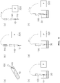
- FIGS. 4a to 4f are views showing a method of using the pipette tip according to the present invention.
- the sample 10 is collected with the pipette tip 100. At this time, a fixed volume of the sample 10 is accurately collected in the capillary tube of the sample collection part 110 by capillary action.
- the pipette tip 100 having the sample 10 collected therein is mounted on a handler for controlling pressure.
- the handler includes an adapter 310 having a flow path formed therethrough and assembled with the pipette tip 100, and a pump configured to generate a positive pressure or negative pressure acting on the pipette tip 100 through the adapter 310.
- the adapter 310 is a hollow tube and is fitted to an upper portion of the pipette tip 100, and is connected to the pump 320 through a pipe.
- the sample in the sample collection part 110 of the pipette tip 100 is introduced into the barrel body 120 by the negative pressure generated by the handler and stored therein.
- the pipette tip 100 mounted on the handler is transferred into a pretreatment solution 20, and the sample 10 and the pretreatment solution 20 are mixed to obtain a mixed liquid 30.
- discharge of the sample 10 in the pipette tip 100 upon transfer is made by the positive pressure generated by the pump 320.
- the mixed liquid 30 is sucked up into the pipette tip 100, and the sucked mixed liquid 30 can be dispensed at a desired position. At this time, the mixed liquid 30 is sucked up into the pipette tip 100 by the negative pressure generated by the pump 320.
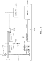
- FIG. 5 is a view showing a configuration of a pipette system according to the present invention.
- a pipette system includes: a guide part for guiding movement of the adapter 310; a driving part for generating a driving force for controlling the movement of the adapter 310 along the guide part; and a control unit for controlling operations of a pump and the driving part.
- the adapter 310 is a module type integrally formed with the pump 320.
- the adapter 310 is provided at a lower surface of the pump 320 such that the pump is moved together with the adapter 310.
- the adapter may be connected to the pump by a flexible hose such that only the adapter can be moved for operation.
- the guide part guides movement of the adapter 310 between a pipette tip site where multiple pipette tips 100 each having a fixed volume of a liquid sample collected therein are located, and a reagent cartridge site where a reagent cartridge 21 is located.
- the guide part is comprised of a vertical ball screw 411, a movable frame 410 guided by the vertical ball screw 411 so as to be moved vertically, and a horizontal ball screw 412 provided horizontally at the movable frame 410 to guide a horizontal movement of the pump 320.
- the pipette tips 100 are stored in a rack 401 provided at a designated position in a state of having the fixed volumes of the liquid samples collected therein, and the reagent cartridge 21 is provided at a side of a transfer device 500.
- the vertical ball screw 411 and the horizontal ball screw 412 are provided to be rotatable by well-known bearings.
- the vertical and horizontal ball screws include a first driving motor 413 and a second driving motor 414 for rotating the ball screws, respectively.
- the control unit 420 controls operations of the pump 320 and the first and second driving motors 413 and 414. In detail, the control unit 420 controls the first driving motor 413 and the second driving motor 413 to control the movement position of the adapter 310. Also, the control unit moves a pipette tip 100 having a liquid sample collected therein to the reagent cartridge 21 to allow the liquid sample to be mixed with a pretreatment solution of the reagent cartridge 21 or dispensed.
- control unit 420 controls the pump 320 such that an appropriate pressure acts on the pipette tip 100 in the process of moving the pipette tip 100 and mixing or dispensing the liquid sample therein, thus preventing leakage of the liquid sample that may occur in the process of moving the pipette tip, and facilitating mixing of the liquid sample with the pretreatment solution or dispensing thereof.
- the reagent cartridge 21 in which the liquid sample is mixed with the pretreatment solution or dispensed is transferred to a test unit 600 by the transfer device 500 and subjected to a test.
- the guide part has been described as performing a biaxial movement in vertical and horizontal directions.
- movement in three axial directions can be performed by additional provision of a guide member and a driving source that are located in directions perpendicular to the vertical and horizontal directions.
Landscapes
- Health & Medical Sciences (AREA)
- Chemical & Material Sciences (AREA)
- Clinical Laboratory Science (AREA)
- Chemical Kinetics & Catalysis (AREA)
- Analytical Chemistry (AREA)
- Life Sciences & Earth Sciences (AREA)
- Physics & Mathematics (AREA)
- Biochemistry (AREA)
- General Health & Medical Sciences (AREA)
- General Physics & Mathematics (AREA)
- Immunology (AREA)
- Pathology (AREA)
- Automatic Analysis And Handling Materials Therefor (AREA)
- Sampling And Sample Adjustment (AREA)
- Devices For Use In Laboratory Experiments (AREA)
Applications Claiming Priority (1)
| Application Number | Priority Date | Filing Date | Title |
|---|---|---|---|
| PCT/KR2016/012256 WO2018079884A1 (fr) | 2016-10-28 | 2016-10-28 | Pointe de pipette et système de pipette |
Publications (3)
| Publication Number | Publication Date |
|---|---|
| EP3533521A1 true EP3533521A1 (fr) | 2019-09-04 |
| EP3533521A4 EP3533521A4 (fr) | 2020-05-27 |
| EP3533521B1 EP3533521B1 (fr) | 2021-06-09 |
Family
ID=62023700
Family Applications (1)
| Application Number | Title | Priority Date | Filing Date |
|---|---|---|---|
| EP16919641.7A Active EP3533521B1 (fr) | 2016-10-28 | 2016-10-28 | Pointe de pipette et système de pipette |
Country Status (3)
| Country | Link |
|---|---|
| EP (1) | EP3533521B1 (fr) |
| ES (1) | ES2878311T3 (fr) |
| WO (1) | WO2018079884A1 (fr) |
Families Citing this family (2)
| Publication number | Priority date | Publication date | Assignee | Title |
|---|---|---|---|---|
| KR102573226B1 (ko) * | 2020-07-29 | 2023-09-01 | 주식회사 아이센스 | 모세혈 수집을 위한 피펫 팁 및 피펫 시스템 |
| CN115106143A (zh) * | 2022-06-29 | 2022-09-27 | 合肥瀚海星点生物科技有限公司 | 一种高精度电动微量液体移液器 |
Family Cites Families (10)
| Publication number | Priority date | Publication date | Assignee | Title |
|---|---|---|---|---|
| US4707337A (en) * | 1986-08-11 | 1987-11-17 | Multi-Technology, Inc. | Medical micro pipette tips for difficult to reach places and related methods |
| US20070081159A1 (en) * | 2005-10-11 | 2007-04-12 | Giffin Kristin M | Apparatus and methods for evaluating an optical property of a liquid sample |
| JP2007209478A (ja) * | 2006-02-08 | 2007-08-23 | Morinaga & Co Ltd | 小動物用採血管及びそれを用いてなる小動物用採血装置 |
| US10105705B2 (en) * | 2006-05-03 | 2018-10-23 | Ncl New Concept Lab Gmbh | Device and method for chemical, biochemical, biological and physical analysis, re-action, assay and more |
| JP2007315793A (ja) * | 2006-05-23 | 2007-12-06 | Neat:Kk | 採取液体を検量するために用いられるピペットチップ、このピペットチップを用いた検量方法および検量装置 |
| EP2098588B1 (fr) * | 2006-11-22 | 2013-01-02 | Altair Corporation | Élément de noyau de pipette, pipette et dispositif de pipette |
| FI20095230A0 (fi) * | 2009-03-09 | 2009-03-09 | Thermo Fisher Scientific Oy | Laimennuskärki |
| EP2752668A3 (fr) * | 2010-07-23 | 2014-10-15 | Beckman Coulter, Inc. | Système ou procédé comprenant des unités analytiques |
| KR101510823B1 (ko) | 2014-04-15 | 2015-04-13 | 포항공과대학교 산학협력단 | 피펫 팁 |
| KR101713172B1 (ko) * | 2015-08-04 | 2017-03-08 | 바디텍메드(주) | 피펫 팁 및 피펫 시스템 |
-
2016
- 2016-10-28 WO PCT/KR2016/012256 patent/WO2018079884A1/fr not_active Ceased
- 2016-10-28 ES ES16919641T patent/ES2878311T3/es active Active
- 2016-10-28 EP EP16919641.7A patent/EP3533521B1/fr active Active
Also Published As
| Publication number | Publication date |
|---|---|
| WO2018079884A1 (fr) | 2018-05-03 |
| EP3533521B1 (fr) | 2021-06-09 |
| EP3533521A4 (fr) | 2020-05-27 |
| ES2878311T3 (es) | 2021-11-18 |
Similar Documents
| Publication | Publication Date | Title |
|---|---|---|
| US4228831A (en) | Probe and syringe drive apparatus | |
| US8114351B2 (en) | Analysis system and method for the analysis of a body fluid sample for an analyte contained therein | |
| US4323537A (en) | Analysis system | |
| EP1074302B1 (fr) | Pipette multicanaux et embouts de pipette pour celle-ci | |
| DE19535046C2 (de) | Handgerät zum Pipettieren und photometrischen Messen von Proben | |
| EP2662671A1 (fr) | Cartouche pour distribuer un fluide | |
| KR101713172B1 (ko) | 피펫 팁 및 피펫 시스템 | |
| US3991616A (en) | Automatic pipetter | |
| US20030073089A1 (en) | Companion cartridge for disposable diagnostic sensing platforms | |
| EP2398591B1 (fr) | Dispositif et procédé de préparation de composants sanguins | |
| US10386277B2 (en) | Container for specimen preparation | |
| US20120101407A1 (en) | Apparatus and method for preparation of small volume of samples | |
| JPH01257268A (ja) | 液体サンプルの稀釈及び混合のための装置及び方法 | |
| US7318359B2 (en) | Sampling means and system for testing a sample liquid | |
| US3337095A (en) | Syringe for automatic proportioning | |
| JP2000262497A (ja) | 分注器具、分注システム及び分注方法 | |
| CN113711056B (zh) | 具有移液器适配性的集成微流控设备 | |
| EP3533521B1 (fr) | Pointe de pipette et système de pipette | |
| JP2004301844A (ja) | 分析装置用プローブガイド付き検査要素ホルダー | |
| EP3244214B1 (fr) | Dispositif pour échantillons liquides avec haute précision dans un analyseur d'échantillon automatisé | |
| US4152939A (en) | Micro-sampling device | |
| EP3751289B1 (fr) | Procédé de surveillance optique d'un dosage d'un liquide à pipetter | |
| EP3222987B1 (fr) | Récipient de dilution d'échantillon | |
| WO2018110052A1 (fr) | Dispositif et procédé de distribution | |
| US20050197538A1 (en) | Reagent and sample introduction plunger device for a syringe |
Legal Events
| Date | Code | Title | Description |
|---|---|---|---|
| STAA | Information on the status of an ep patent application or granted ep patent |
Free format text: STATUS: THE INTERNATIONAL PUBLICATION HAS BEEN MADE |
|
| PUAI | Public reference made under article 153(3) epc to a published international application that has entered the european phase |
Free format text: ORIGINAL CODE: 0009012 |
|
| STAA | Information on the status of an ep patent application or granted ep patent |
Free format text: STATUS: REQUEST FOR EXAMINATION WAS MADE |
|
| 17P | Request for examination filed |
Effective date: 20190527 |
|
| AK | Designated contracting states |
Kind code of ref document: A1 Designated state(s): AL AT BE BG CH CY CZ DE DK EE ES FI FR GB GR HR HU IE IS IT LI LT LU LV MC MK MT NL NO PL PT RO RS SE SI SK SM TR |
|
| AX | Request for extension of the european patent |
Extension state: BA ME |
|
| DAV | Request for validation of the european patent (deleted) | ||
| DAX | Request for extension of the european patent (deleted) | ||
| A4 | Supplementary search report drawn up and despatched |
Effective date: 20200424 |
|
| RIC1 | Information provided on ipc code assigned before grant |
Ipc: B01L 3/02 20060101AFI20200420BHEP Ipc: G01N 35/10 20060101ALI20200420BHEP |
|
| GRAP | Despatch of communication of intention to grant a patent |
Free format text: ORIGINAL CODE: EPIDOSNIGR1 |
|
| STAA | Information on the status of an ep patent application or granted ep patent |
Free format text: STATUS: GRANT OF PATENT IS INTENDED |
|
| INTG | Intention to grant announced |
Effective date: 20210302 |
|
| GRAS | Grant fee paid |
Free format text: ORIGINAL CODE: EPIDOSNIGR3 |
|
| GRAA | (expected) grant |
Free format text: ORIGINAL CODE: 0009210 |
|
| STAA | Information on the status of an ep patent application or granted ep patent |
Free format text: STATUS: THE PATENT HAS BEEN GRANTED |
|
| AK | Designated contracting states |
Kind code of ref document: B1 Designated state(s): AL AT BE BG CH CY CZ DE DK EE ES FI FR GB GR HR HU IE IS IT LI LT LU LV MC MK MT NL NO PL PT RO RS SE SI SK SM TR |
|
| REG | Reference to a national code |
Ref country code: GB Ref legal event code: FG4D |
|
| REG | Reference to a national code |
Ref country code: CH Ref legal event code: EP Ref country code: AT Ref legal event code: REF Ref document number: 1400020 Country of ref document: AT Kind code of ref document: T Effective date: 20210615 |
|
| REG | Reference to a national code |
Ref country code: DE Ref legal event code: R096 Ref document number: 602016059264 Country of ref document: DE |
|
| REG | Reference to a national code |
Ref country code: IE Ref legal event code: FG4D |
|
| REG | Reference to a national code |
Ref country code: LT Ref legal event code: MG9D |
|
| PG25 | Lapsed in a contracting state [announced via postgrant information from national office to epo] |
Ref country code: HR Free format text: LAPSE BECAUSE OF FAILURE TO SUBMIT A TRANSLATION OF THE DESCRIPTION OR TO PAY THE FEE WITHIN THE PRESCRIBED TIME-LIMIT Effective date: 20210609 Ref country code: BG Free format text: LAPSE BECAUSE OF FAILURE TO SUBMIT A TRANSLATION OF THE DESCRIPTION OR TO PAY THE FEE WITHIN THE PRESCRIBED TIME-LIMIT Effective date: 20210909 Ref country code: FI Free format text: LAPSE BECAUSE OF FAILURE TO SUBMIT A TRANSLATION OF THE DESCRIPTION OR TO PAY THE FEE WITHIN THE PRESCRIBED TIME-LIMIT Effective date: 20210609 Ref country code: LT Free format text: LAPSE BECAUSE OF FAILURE TO SUBMIT A TRANSLATION OF THE DESCRIPTION OR TO PAY THE FEE WITHIN THE PRESCRIBED TIME-LIMIT Effective date: 20210609 |
|
| REG | Reference to a national code |
Ref country code: AT Ref legal event code: MK05 Ref document number: 1400020 Country of ref document: AT Kind code of ref document: T Effective date: 20210609 |
|
| REG | Reference to a national code |
Ref country code: NL Ref legal event code: MP Effective date: 20210609 |
|
| REG | Reference to a national code |
Ref country code: ES Ref legal event code: FG2A Ref document number: 2878311 Country of ref document: ES Kind code of ref document: T3 Effective date: 20211118 |
|
| PG25 | Lapsed in a contracting state [announced via postgrant information from national office to epo] |
Ref country code: GR Free format text: LAPSE BECAUSE OF FAILURE TO SUBMIT A TRANSLATION OF THE DESCRIPTION OR TO PAY THE FEE WITHIN THE PRESCRIBED TIME-LIMIT Effective date: 20210910 Ref country code: LV Free format text: LAPSE BECAUSE OF FAILURE TO SUBMIT A TRANSLATION OF THE DESCRIPTION OR TO PAY THE FEE WITHIN THE PRESCRIBED TIME-LIMIT Effective date: 20210609 Ref country code: NO Free format text: LAPSE BECAUSE OF FAILURE TO SUBMIT A TRANSLATION OF THE DESCRIPTION OR TO PAY THE FEE WITHIN THE PRESCRIBED TIME-LIMIT Effective date: 20210909 Ref country code: RS Free format text: LAPSE BECAUSE OF FAILURE TO SUBMIT A TRANSLATION OF THE DESCRIPTION OR TO PAY THE FEE WITHIN THE PRESCRIBED TIME-LIMIT Effective date: 20210609 Ref country code: SE Free format text: LAPSE BECAUSE OF FAILURE TO SUBMIT A TRANSLATION OF THE DESCRIPTION OR TO PAY THE FEE WITHIN THE PRESCRIBED TIME-LIMIT Effective date: 20210609 |
|
| PG25 | Lapsed in a contracting state [announced via postgrant information from national office to epo] |
Ref country code: CZ Free format text: LAPSE BECAUSE OF FAILURE TO SUBMIT A TRANSLATION OF THE DESCRIPTION OR TO PAY THE FEE WITHIN THE PRESCRIBED TIME-LIMIT Effective date: 20210609 Ref country code: EE Free format text: LAPSE BECAUSE OF FAILURE TO SUBMIT A TRANSLATION OF THE DESCRIPTION OR TO PAY THE FEE WITHIN THE PRESCRIBED TIME-LIMIT Effective date: 20210609 Ref country code: AT Free format text: LAPSE BECAUSE OF FAILURE TO SUBMIT A TRANSLATION OF THE DESCRIPTION OR TO PAY THE FEE WITHIN THE PRESCRIBED TIME-LIMIT Effective date: 20210609 Ref country code: NL Free format text: LAPSE BECAUSE OF FAILURE TO SUBMIT A TRANSLATION OF THE DESCRIPTION OR TO PAY THE FEE WITHIN THE PRESCRIBED TIME-LIMIT Effective date: 20210609 Ref country code: PT Free format text: LAPSE BECAUSE OF FAILURE TO SUBMIT A TRANSLATION OF THE DESCRIPTION OR TO PAY THE FEE WITHIN THE PRESCRIBED TIME-LIMIT Effective date: 20211011 Ref country code: RO Free format text: LAPSE BECAUSE OF FAILURE TO SUBMIT A TRANSLATION OF THE DESCRIPTION OR TO PAY THE FEE WITHIN THE PRESCRIBED TIME-LIMIT Effective date: 20210609 Ref country code: SK Free format text: LAPSE BECAUSE OF FAILURE TO SUBMIT A TRANSLATION OF THE DESCRIPTION OR TO PAY THE FEE WITHIN THE PRESCRIBED TIME-LIMIT Effective date: 20210609 Ref country code: SM Free format text: LAPSE BECAUSE OF FAILURE TO SUBMIT A TRANSLATION OF THE DESCRIPTION OR TO PAY THE FEE WITHIN THE PRESCRIBED TIME-LIMIT Effective date: 20210609 |
|
| PG25 | Lapsed in a contracting state [announced via postgrant information from national office to epo] |
Ref country code: PL Free format text: LAPSE BECAUSE OF FAILURE TO SUBMIT A TRANSLATION OF THE DESCRIPTION OR TO PAY THE FEE WITHIN THE PRESCRIBED TIME-LIMIT Effective date: 20210609 |
|
| REG | Reference to a national code |
Ref country code: DE Ref legal event code: R097 Ref document number: 602016059264 Country of ref document: DE |
|
| PLBE | No opposition filed within time limit |
Free format text: ORIGINAL CODE: 0009261 |
|
| STAA | Information on the status of an ep patent application or granted ep patent |
Free format text: STATUS: NO OPPOSITION FILED WITHIN TIME LIMIT |
|
| PG25 | Lapsed in a contracting state [announced via postgrant information from national office to epo] |
Ref country code: DK Free format text: LAPSE BECAUSE OF FAILURE TO SUBMIT A TRANSLATION OF THE DESCRIPTION OR TO PAY THE FEE WITHIN THE PRESCRIBED TIME-LIMIT Effective date: 20210609 |
|
| 26N | No opposition filed |
Effective date: 20220310 |
|
| PG25 | Lapsed in a contracting state [announced via postgrant information from national office to epo] |
Ref country code: AL Free format text: LAPSE BECAUSE OF FAILURE TO SUBMIT A TRANSLATION OF THE DESCRIPTION OR TO PAY THE FEE WITHIN THE PRESCRIBED TIME-LIMIT Effective date: 20210609 |
|
| REG | Reference to a national code |
Ref country code: BE Ref legal event code: MM Effective date: 20211031 |
|
| PG25 | Lapsed in a contracting state [announced via postgrant information from national office to epo] |
Ref country code: MC Free format text: LAPSE BECAUSE OF FAILURE TO SUBMIT A TRANSLATION OF THE DESCRIPTION OR TO PAY THE FEE WITHIN THE PRESCRIBED TIME-LIMIT Effective date: 20210609 |
|
| PG25 | Lapsed in a contracting state [announced via postgrant information from national office to epo] |
Ref country code: LU Free format text: LAPSE BECAUSE OF NON-PAYMENT OF DUE FEES Effective date: 20211028 Ref country code: BE Free format text: LAPSE BECAUSE OF NON-PAYMENT OF DUE FEES Effective date: 20211031 |
|
| PG25 | Lapsed in a contracting state [announced via postgrant information from national office to epo] |
Ref country code: IE Free format text: LAPSE BECAUSE OF NON-PAYMENT OF DUE FEES Effective date: 20211028 |
|
| PG25 | Lapsed in a contracting state [announced via postgrant information from national office to epo] |
Ref country code: CY Free format text: LAPSE BECAUSE OF FAILURE TO SUBMIT A TRANSLATION OF THE DESCRIPTION OR TO PAY THE FEE WITHIN THE PRESCRIBED TIME-LIMIT Effective date: 20210609 |
|
| PG25 | Lapsed in a contracting state [announced via postgrant information from national office to epo] |
Ref country code: HU Free format text: LAPSE BECAUSE OF FAILURE TO SUBMIT A TRANSLATION OF THE DESCRIPTION OR TO PAY THE FEE WITHIN THE PRESCRIBED TIME-LIMIT; INVALID AB INITIO Effective date: 20161028 |
|
| PG25 | Lapsed in a contracting state [announced via postgrant information from national office to epo] |
Ref country code: MK Free format text: LAPSE BECAUSE OF FAILURE TO SUBMIT A TRANSLATION OF THE DESCRIPTION OR TO PAY THE FEE WITHIN THE PRESCRIBED TIME-LIMIT Effective date: 20210609 |
|
| PG25 | Lapsed in a contracting state [announced via postgrant information from national office to epo] |
Ref country code: MT Free format text: LAPSE BECAUSE OF FAILURE TO SUBMIT A TRANSLATION OF THE DESCRIPTION OR TO PAY THE FEE WITHIN THE PRESCRIBED TIME-LIMIT Effective date: 20210609 |
|
| REG | Reference to a national code |
Ref country code: CH Ref legal event code: U11 Free format text: ST27 STATUS EVENT CODE: U-0-0-U10-U11 (AS PROVIDED BY THE NATIONAL OFFICE) Effective date: 20251101 |
|
| PG25 | Lapsed in a contracting state [announced via postgrant information from national office to epo] |
Ref country code: TR Free format text: LAPSE BECAUSE OF FAILURE TO SUBMIT A TRANSLATION OF THE DESCRIPTION OR TO PAY THE FEE WITHIN THE PRESCRIBED TIME-LIMIT Effective date: 20210609 |
|
| PGFP | Annual fee paid to national office [announced via postgrant information from national office to epo] |
Ref country code: DE Payment date: 20251029 Year of fee payment: 10 |
|
| PGFP | Annual fee paid to national office [announced via postgrant information from national office to epo] |
Ref country code: GB Payment date: 20251027 Year of fee payment: 10 |
|
| PGFP | Annual fee paid to national office [announced via postgrant information from national office to epo] |
Ref country code: IT Payment date: 20251021 Year of fee payment: 10 |
|
| PGFP | Annual fee paid to national office [announced via postgrant information from national office to epo] |
Ref country code: FR Payment date: 20251027 Year of fee payment: 10 |
|
| PGFP | Annual fee paid to national office [announced via postgrant information from national office to epo] |
Ref country code: CH Payment date: 20251101 Year of fee payment: 10 |
|
| PGFP | Annual fee paid to national office [announced via postgrant information from national office to epo] |
Ref country code: ES Payment date: 20251103 Year of fee payment: 10 |