EP3533582A1 - Récipient de transport pourvu de film dans le moule - Google Patents
Récipient de transport pourvu de film dans le moule Download PDFInfo
- Publication number
- EP3533582A1 EP3533582A1 EP18159712.1A EP18159712A EP3533582A1 EP 3533582 A1 EP3533582 A1 EP 3533582A1 EP 18159712 A EP18159712 A EP 18159712A EP 3533582 A1 EP3533582 A1 EP 3533582A1
- Authority
- EP
- European Patent Office
- Prior art keywords
- mold
- film
- region
- relief element
- transport container
- Prior art date
- Legal status (The legal status is an assumption and is not a legal conclusion. Google has not performed a legal analysis and makes no representation as to the accuracy of the status listed.)
- Granted
Links
Images




Classifications
-
- B—PERFORMING OPERATIONS; TRANSPORTING
- B29—WORKING OF PLASTICS; WORKING OF SUBSTANCES IN A PLASTIC STATE IN GENERAL
- B29C—SHAPING OR JOINING OF PLASTICS; SHAPING OF MATERIAL IN A PLASTIC STATE, NOT OTHERWISE PROVIDED FOR; AFTER-TREATMENT OF THE SHAPED PRODUCTS, e.g. REPAIRING
- B29C45/00—Injection moulding, i.e. forcing the required volume of moulding material through a nozzle into a closed mould; Apparatus therefor
- B29C45/14—Injection moulding, i.e. forcing the required volume of moulding material through a nozzle into a closed mould; Apparatus therefor incorporating preformed parts or layers, e.g. injection moulding around inserts or for coating articles
- B29C45/1418—Injection moulding, i.e. forcing the required volume of moulding material through a nozzle into a closed mould; Apparatus therefor incorporating preformed parts or layers, e.g. injection moulding around inserts or for coating articles the inserts being deformed or preformed, e.g. by the injection pressure
-
- B—PERFORMING OPERATIONS; TRANSPORTING
- B29—WORKING OF PLASTICS; WORKING OF SUBSTANCES IN A PLASTIC STATE IN GENERAL
- B29C—SHAPING OR JOINING OF PLASTICS; SHAPING OF MATERIAL IN A PLASTIC STATE, NOT OTHERWISE PROVIDED FOR; AFTER-TREATMENT OF THE SHAPED PRODUCTS, e.g. REPAIRING
- B29C45/00—Injection moulding, i.e. forcing the required volume of moulding material through a nozzle into a closed mould; Apparatus therefor
- B29C45/14—Injection moulding, i.e. forcing the required volume of moulding material through a nozzle into a closed mould; Apparatus therefor incorporating preformed parts or layers, e.g. injection moulding around inserts or for coating articles
- B29C45/1418—Injection moulding, i.e. forcing the required volume of moulding material through a nozzle into a closed mould; Apparatus therefor incorporating preformed parts or layers, e.g. injection moulding around inserts or for coating articles the inserts being deformed or preformed, e.g. by the injection pressure
- B29C2045/14237—Injection moulding, i.e. forcing the required volume of moulding material through a nozzle into a closed mould; Apparatus therefor incorporating preformed parts or layers, e.g. injection moulding around inserts or for coating articles the inserts being deformed or preformed, e.g. by the injection pressure the inserts being deformed or preformed outside the mould or mould cavity
-
- B—PERFORMING OPERATIONS; TRANSPORTING
- B29—WORKING OF PLASTICS; WORKING OF SUBSTANCES IN A PLASTIC STATE IN GENERAL
- B29C—SHAPING OR JOINING OF PLASTICS; SHAPING OF MATERIAL IN A PLASTIC STATE, NOT OTHERWISE PROVIDED FOR; AFTER-TREATMENT OF THE SHAPED PRODUCTS, e.g. REPAIRING
- B29C45/00—Injection moulding, i.e. forcing the required volume of moulding material through a nozzle into a closed mould; Apparatus therefor
- B29C45/14—Injection moulding, i.e. forcing the required volume of moulding material through a nozzle into a closed mould; Apparatus therefor incorporating preformed parts or layers, e.g. injection moulding around inserts or for coating articles
- B29C2045/1486—Details, accessories and auxiliary operations
- B29C2045/14901—Coating a sheet-like insert smaller than the dimensions of the adjacent mould wall
- B29C2045/14918—Coating a sheet-like insert smaller than the dimensions of the adjacent mould wall in-mould-labelling
-
- B—PERFORMING OPERATIONS; TRANSPORTING
- B29—WORKING OF PLASTICS; WORKING OF SUBSTANCES IN A PLASTIC STATE IN GENERAL
- B29L—INDEXING SCHEME ASSOCIATED WITH SUBCLASS B29C, RELATING TO PARTICULAR ARTICLES
- B29L2031/00—Other particular articles
- B29L2031/712—Containers; Packaging elements or accessories, Packages
- B29L2031/7134—Crates, e.g. for bottles
Definitions
- the invention relates to a transport container, in particular a bottle crate for holding beverage bottles or bottle containers, and a method for producing such a transport container.
- a transport container is known with a container base body having a bottom and four side walls, wherein at least one of the side walls has a base surface and at least one with respect to the base raised relief element or at least one recessed with respect to the base formed relief element. It is provided that the side wall has one or more at least partially each of the base surface and the relief element or the inverted relief element covering inmould film (s).
- the in the EP 2 554 485 A1 The disclosed inmould foil covers an offset structure projecting into the wall plane, for example a wood grain, and at the same time elevated and / or recessed text elements opposite the base surface. Both the offset structure projecting into the wall plane and the raised and / or recessed text elements have a maximum offset height of 2 mm with respect to the base surface.
- the maximum offset height of 2 mm is due to the manufacturing process of the transport container, in which the in-mold film is inserted into an injection mold and back-injected by the plastic forming the container body.
- the invention is based on the object to provide a transport container and a method for its production, which overcome the disadvantages of the prior art.
- a transport container for holding beverage bottles or bottle containers, comprising a container base body having a bottom and four side walls, it is provided that at least one of the side walls a base surface and at least one with respect to the base raised relief element or at least one with respect to the Base surface recessed formed inverted relief element, wherein the side wall has at least one at least partially each of the base surface and the relief element or the inverted relief element covering in-mold film, and wherein the in-mold film has a base area associated with the first region and a relief element or inverted relief element associated second area. Furthermore, it is provided that the in-mold film has at least one well-defined compensation recess in a transition region from the first region to the second region.
- “Well-defined” means either the shape or the size or the shape and size of the compensation recess.
- the well-defined compensation recess of the in-mold film is particularly well defined in that it is determined in a preprocessing step of the in-mold film before injection molding of the in-mold film in the injection mold in shape and size.
- the well-defined compensation recess is thus created by preconditioning the in-mold film.
- the preconditioning of the inmould film ensures that the well-defined compensation recess in the mold after injection molding desired shape and size is located at the desired location, namely in the transition region from the first region to the second region of the in-mold film.
- the preconditioning advantageously has the effect that the pressure on the in-mold film is reduced during the injection molding in the transition region from the first to the second region, so that targeted undefined tearing of the in-mold film and associated distortion of the printing in the region of the relief element or of the inverted Relief element is counteracted.
- the transport container according to the invention thus receives a pleasing, well-defined optical impression.
- the well-defined recess is formed by a region of reduced film thickness.
- a preconditioning in the form of a region with reduced film thickness is applied for this purpose, or it is added to the in-mold film by manipulation, for example by a robotic device, prior to insertion into the injection mold.
- the area of reduced film thickness is stretched so that after injection molding, there is still an area of reduced film thickness without breaking the inmold film in this area.
- the well-defined compensation recess is formed by an opening in the in-mold film.
- the opening in the in-mold film can be added, for example, from an opening already present when the in-mold film is fed to the injection-molding element as appropriate preconditioning of the in-mold film, or by manipulation, for example, by a robotic device prior to insertion into the injection mold of the in-mold film Opening arose.
- the opening results from a well-defined rupturing of a preconditioning in the form of a region with a reduced film thickness.
- the opening in the in-mold film is already present as a preconditioning when inserting the in-mold film in the injection mold, the opening during injection molding due to the pressures acting on the film can enlarge or connect with other openings, this is a process that leads to a well-defined compensating recess in the context of the invention.
- the opening for example, will tear in a direction perpendicular to the train, or will tear in a direction in which there is a nearby further opening.
- the film may crack during injection molding, with the crack advantageously limited to the area defined by the preconditioning, i. H. spatially in the field of preconditioning and is determined by this.
- the preconditioning in the form of the region with reduced film thickness can be formed, for example, by stamping or by chip removal.
- it may comprise a film hinge area.
- the preconditioning in the form of the opening can also be formed by a punching.
- the preconditioning in the form of the opening may be formed by a perforation, which means a plurality of holes along a predetermined line. Further alternatively, the preconditioning may be formed by a cut.
- the well-defined compensating recess completely surrounds the relief element or the inverted relief element.
- the well-defined compensation recess partially surrounds the relief element or the inverted relief element.
- the in-mold film has webs in the transition region from the first region to the second region, which interconnects the first region and the second region.
- the first region of the inmould film with the second region of the inmould film is advantageously connected to one another in such a way that the print image of the inmould film which covers the relief element or inverted relief element can be deliberately placed thereon without it comes to an unwanted lateral offset.
- the webs are preferably formed from 50 microns to 1 mm wide. As a result, the impression that results from the presence of the webs on the transition region, as little as possible.
- the first and second regions are interconnected at a plurality of locations, for example at more than twenty locations.
- the first and second regions are connected to one another at less than ten points, less than five points, at four, three, in particular at two points, at one point or at no point.
- the optical impression of the transition region in which the relief element rises or the inverted relief element sinks is advantageously influenced by the webs in only a few places or even at no point.
- the relief element or the inverted relief element is advantageously more than 0.5 mm, preferably more than 1 mm, more preferably more than 1.5 mm, even more preferably more than 2 mm and in particular from 2 mm to 5 mm, from 2 mm to 4 mm or from 2 mm to 3 mm from the base raised or recessed formed.
- the relief element or the inverted relief element can have a substantially stronger profile, i. have a greater maximum offset height than in previous in-mold films, without the visual impression of the printed image on the in-mold film in the second areas in which the in-mold film covers the relief elements or inverted relief elements, is affected.
- the relief element or inverted relief element can, for. As a letter and / or a symbol, a logo, a brand or even an advertising letter include.
- the transport container has a bumper or bumpers
- the raised relief elements are formed less pronounced compared to the edge of the edge or the bumpers with respect to the base of the side wall.
- a plurality or all of the relief elements and / or inverted relief elements provided on the transport container are covered with one or more in-mold films.
- a multiplicity of preconditioning can advantageously be provided along the contours of all the relief elements or inverted relief elements, so that the in-mold film is or is inverted in the first areas in which it covers the base area and in the second areas in which it covers the relief elements Covered relief elements, not uncontrollably rips.
- the in-mold film has a lacquer layer.
- lacquered in-mold foils which already have a lacquer coating prior to injection molding, it has hitherto not been possible to arrange these on sidewalls with relief elements or inverted relief elements.
- Well-defined compensating recesses in the transition regions advantageously prevent the lacquer layer from bursting or cracking during injection molding, so that completely new design possibilities of the transport container are present with the present invention.
- the in-mold film has a lamination.
- laminated in-mold films which already have a lamination prior to injection molding it has hitherto not been possible to arrange these on side walls with relief elements which are raised more than 2 mm, or with inverted relief elements which are recessed more than 2 mm.
- Well-defined compensation recesses in the transition regions advantageously prevent the lamination from breaking during the injection molding process, so that completely new optical impressions of the transport container are made possible with the present invention.
- the inmould film can have a matt effect partially or completely.
- the in-mold film has a matt effect only in the first region or only in the second region.
- the in-mold film is made matt in the first region and high-gloss in the second region or vice versa.
- a matt effect of the in-mold film can be produced for example by structuring, which is brought about in the injection process by impressing a structure located on the tool jaw. Structures whose grain size corresponds approximately to a 250 grain with structure sizes of 10 microns to 80 microns, thereby leading to a matt-acting surface of the in-mold film. Extremely smooth sections of the base area, however, create a glossy finish in the inmould film. Suitable on the tool jaw structures are, for example, erosion, especially erosion according to VDI standards such. B. VDI 36.
- Alternative suitable located on the tool jaw structures may include brushed, grained, etched, and / or milled structures in appropriate grain size.
- the matte effect may also be inherent in or on the inmold prior to injection molding.
- the matte effect can z. B. by using a translucent in-mold film with a textured surface arise and / or by a color imprint or order of a paint.
- the structuring of the surface can be produced, for example, by passing the in-mold film through a pair of rollers, wherein two intermeshing pressure-exiting rollers with a structured surface deform the translucent film from both sides and thereby double the depth (eg -0.5 mm) or increase (eg + 0.5 mm) without overstretching of the film.
- the roller may also be designed such that structured and unstructured surfaces are adjacent to one another.
- the base may be smooth or have a particular brushed, eroded, grained, etched, polished, mirror polished and / or milled 3D background structure.
- the 3D background structure may comprise, for example, less than 1 mm, in particular 0.5 mm raised and / or recessed features.
- the 3D background structure may in particular comprise area-like components which z. B. natural and / or industrial surface structures are modeled, for example, wood grain structures, stone or granite pattern, Riffelblechobervid or the like.
- each side of the transport container is provided with at least one inmould film.
- Inmould foils which run around an edge or corner of the transport container, are also possible.
- the side wall has at least partially superimposed inmould films covering each at least the base surface and the relief element or the inverted relief element, wherein one or both of the in-mold films in the transition region from the first region to the second region have at least one well-defined compensation recess. It can be provided that the side wall has two full-surface superimposed in-mold films or two in-mold films, which overlap only partially.
- both in-mold films have well-defined compensation recesses, the well-defined compensation recesses being arranged one above the other.
- one or both in-mold films have a lamination or coating and have well-defined compensation recesses in order to prevent impairment of the lacquer layer or the lamination.
- the measures of the invention it is possible with the measures of the invention to place two in-mold films one above the other, wherein these can also be designed differently, for example.
- one of the inmould films is matt and the other of the inmould films has a high gloss finish.
- an in-mold film is also provided for use in a transport container described above, wherein the in-mold film has at least one preconditioning in a transition region from the first region to the second region.
- the in-mold film has, for example, a thickness of 5 ⁇ m to 190 ⁇ m.
- the in-mold film may have a thickness of 60 .mu.m to 110 .mu.m.
- a PE film polyethylene film
- PP film polypropylene film
- PET film polyethylene terephthalate film
- in-mold film can be used as a base film, which can be printed on one or both sides to produce a color and / or or to obtain information in the desired representation.
- the printing of the in-mold film can be done for example with an offset printing and / or with a flexographic printing and / or with a gravure printing and / or with a digital printing and / or with a screen printing.
- offset printing can be provided to provide only the area with a basic white color printing on which printed information, for. As letters or logos is located.
- an in-mold film in which the base film has a first printing on the side facing the container base body and has a second printing on the side facing away from the container base body.
- the shape and color of the first printing and the second printing correspond to each other.
- the first print layer can advantageously maintain the optical effect, so that the consumer does not notice the defect.
- the base film of the in-mold film is colored translucently in the color of the container base body. Furthermore, the base film of the in-mold film is preferably equipped with heat and light stabilizers (HALS Stabifisatoren).
- HALS Stabifisatoren heat and light stabilizers
- the matte effect can z. B. be produced by a translucent in-mold film with a textured surface and / or by a color imprint or order of a paint.
- the structured surface can be produced, for example, by passing the base film or in-mold film through a pair of rolls, wherein two intermeshing pressure-exerting rolls with a structured surface deform the translucent film from both sides and thereby have a double depth (eg -0.5 mm) or Increase (eg + 0.5 mm) without overstretching the film.
- the roller may also be designed such that structured and unstructured surfaces are adjacent to one another.
- the PE, PP or PET base film is provided in an advantageous embodiment with a lamination or with a protective lacquer layer.
- laminated in-mold films in which the base film is accommodated in a kind of shell are possible.
- Such laminations and protective coatings help to protect the print layers of the base film against damage, for example by, for example by, forkarkratzende components of a transport device, by stacking and palletizing with other transport containers or in everyday use.
- a laminated film is understood to mean a film in which the base film is coated with a plastic protective layer which may possibly still have an adhesion-promoting underside.
- the lamination can be realized by a PET transparent film.
- the lamination can alternatively be done by a PP film.
- a transparent film may be provided.
- the lamination of the inmould film may also be equipped with heat and light stabilizers (HALS stabilizers).
- HALS stabilizers heat and light stabilizers
- the lamination or the protective lacquer layer can also be printed.
- the in-mold film supplied in step a) has at least one preconditioning in a transition region from the first region to the second region.
- the well-defined compensation recess in the in-mold film advantageously forms.
- the in-mold film is supplied to the injection molding tool as a band product, in particular a roll product.
- a band product in particular a roll product.
- the in-mold films are separated by means of a robot device. Compared to a manual separation, this means a gain in precision and speed.
- the use of the robotic device for inserting the inmould foils into the The tool jaw of the injection molding tool enables a particularly precise positioning of the inmould foil in the injection molding tool so that the desired appearance of the transport container is ensured, while at the same time providing high throughput.
- the feeding of the inmould film can be done manually.
- the feeding of the in-mold films is effected by a feed device, which may comprise, for example, coils, conveyor rollers and / or wheels.
- the guiding of the in-mold foils can be carried out by rollers or rollers lying all over the surface, or by one or more wheels which are coupled with each other rather selectively on the inmould foil.
- the inmould film is fed from a roll through a system of several rolls or wheels until it reaches the robot device.
- a horizontal guide, a vertical guide or a section horizontal and vertical guide can be provided.
- the in-mold film can first be unwound from a high-lying roller by means of a lower-lying pair of rollers or wheels and thereafter, if appropriate, be continued horizontally by further pairs of rollers or wheels.
- the acceptance position by the robot device may be a horizontal position or a vertical position of the inmould foil.
- the inmould foil can be supported on the opposite side of the robot device, for example by a rear wall, a support or by a magazine, in order to stop the manipulation by the robot device on the back.
- the inmould film in the form of band goods, in particular rolls, can be in wound form on a spindle or roll. It may in some embodiments again on a substrate, for. B. a further plastic film may be arranged, from which it is separated in the step of separating.
- the robotic device may include both a robotic arm and a plurality of cooperating robotic arms whose control is coordinated. At least one robot arm of the robot device can be designed to separate the in-mold foils and has corresponding devices for this purpose. The same or another robot arm of the robot device can be designed to insert the singulated in-mold film into a tool jaw of the injection molding tool for the subsequent back-injection and for this purpose has further corresponding devices.
- At least one robotic arm of the robotic device may comprise a recognition device comprising, for example, cameras, CCD bars or other suitable sensors for identifying the in-mold foils to be singulated.
- At least one robotic arm of the robotic device may include a manipulating head, which may in particular include suction, gripping, cutting, punching and / or chipping devices to enable the in-mold foil to be singulated.
- a manipulating head which may in particular include suction, gripping, cutting, punching and / or chipping devices to enable the in-mold foil to be singulated.
- This or another Manipulierkopf the robot device may also be configured, for. B. by means of joints and appropriate control to transfer the isolated in-mold film to the injection mold and to position in the injection mold.
- the tool jaw of the injection molding tool can be configured in one piece or in several parts and comprise both flat and angular areas. It can define both a side wall of the subsequent transport container, but also a corner region of the transport container or more, z. B. also circumferential side walls.
- the inmould films fed to the injection molding tool as stripware have outer contours with preconditioning in the form of regions with reduced film thicknesses or openings.
- the preconditioning effects for example, that the outer contours can be recognized by the robot device in a simple manner.
- the robot device recognizes the preconditioning by optical sensors, for. B. by a camera, or in transparent films z. B. by a confocal measuring device.
- the robotic device preconditioning by determining the thickness of the in-mold film, z. B. by means of non-contact methods, eg. B. by means of inductive or capacitive sensors, or recognizes by scanning.
- the robot device isolates the in-mold films corresponding to the outer contours by means of vacuum suction or by means of electrostatic charging.
- the preconditioning of the in-mold films and the vacuum channels on the manipulating head of Robot device executed in such a way and coordinated with each other, that is separated by applying the vacuum, the in-mold film according to its outer contour of the band.
- an electrostatic field is applied to the manipulation head of the robotic device, wherein the in-mold foil is separated from the band by the static charge.
- the preconditioning can be designed in particular as thin film hinges or as a perforation or as extended openings with webs that tear at a defined tensile stress.
- the robot device singulates the in-mold films according to predetermined or recognized outer contours. In particular, it can be provided that the robot device punches or cuts out the in-mold films.
- preconditioned, e.g. B. punched in-mold films detected by the robot device for example by means of a graphics chip or thickness measurement, and then punched out of the robot device to the end or cut to the end.
- the robot device recognizes the printing of the in-mold film by means of a graphics chip and accordingly the detected information isolated along its outer contours.
- the robot device according to predetermined position and distance definitions the in-mold films separated along their outer contours.
- the inmould films supplied to the injection molding tool as a strip product have inside contours within the outer contour with preconditioning in the form of regions with reduced film thicknesses or openings.
- the inner contours located within the outer contour can be present both alternatively and in addition to outer contours with preconditioning.
- the robot device can at least partially punch, punch, cut or perforate inner contours of the in-mold foils located within the outer contour in order to form preconditioning of the in-mold foils.
- Inner contours with preconditioning can also be used Both already present in the supply of in-mold films as taught by the robot device of the in-mold film, ie produced.
- pass-through openings or viewing windows of the transport container are present or produced in the form of inner contours with preconditioning of the in-mold film.
- areas which are later assigned to a relief element or an inverted relief element of the transport container in the transport container to be present or produced in the form of inner contours with preconditioning.
- the robot device isolates island regions of the in-mold films corresponding to the inner contours.
- the robot device can isolate the island areas by means of vacuum suction.
- it may be provided to separate the island areas by means of electrostatic charging, punching, cutting or perforation.
- the in-mold film is released along its outer contour from the belt and that in addition one or more located within the outer contour island regions of the in-mold films are present, in turn, independent of, or in other words unconnected with, which is determined by the outer contour area of the inmould film. It can be provided that the island regions are inserted individually into the tool jaw of the injection molding tool.
- the robot device isolates such preconditions present as pass-through openings or viewing windows and does not singulate such preconditionings assigned to the relief element or inverted relief element, or vice versa. It can also be provided that the robot device with all the inner contours Preconditioning isolated as island areas or not isolated all inner contours with preconditioning.
- the robot device separates an in-mold film from the belt by means of vacuum suction according to its outer contour and additionally isolates a penetration opening or a viewing opening of the transport container by means of a further vacuum edge with respect to the singulated in-mold film, so that two disjoint in-mold films are formed. Film areas exist.
- the area of the in-mold film determined by the outer contour is held on the tool jaw by a vacuum edge provided at the injection mold and released by the robot device.
- the robot device separates an in-mold film from the belt by means of vacuum suction according to its outer contour and additionally isolates, with the aid of a further vacuum edge, a region of the in-mold film which is provided for a relief element or inverted relief element, with respect to FIG isolated in-mold film, so that two disjoint in-mold film areas exist.
- the area of the in-mold film determined by the outer contour is released by the robot device and held on the tool jaw by a vacuum edge provided at the injection mold.
- a separate vacuum edge is provided in the tool jaw.
- the tool jaw of the injection molding tool has a tool jaw base surface and at least one raised with respect to the tool jaw base surface ceremonibackenreliefelement or at least one with respect to the tool base surface recessed formed inverted horrbackenreliefelement.
- an in-mold film is inserted into the injection molding tool in step c) in such a way that after the back injection it has a first region in which the inmould film at least partially covers a base surface of the transport container corresponding to the tool jaw base surface, and a second Area in which the inmould foil covers an inverted relief element or relief element of the transport container corresponding to the tool jaw relief element or the inverted tool jaw relief element.
- a transport container can thus be provided with an in-mold film which at least partially covers the base surface and the relief element or the inverted relief element.
- At least one inner contour of the in-mold film corresponds to a transition region from the first region to the second region.
- a preconditioning in the form of an area with a reduced film thickness or an opening is thus provided in the transition area.
- the preconditioning may have been generated by the robotic device or else have already been supplied as a strip product, in particular rolled goods.
- the retention of the in-mold film in the position in step c) can be done for example by so-called vacuum edges.
- Vacuum edges denote z.
- the holding of the in-mold film in the position in step c) may alternatively or additionally be carried out at least in sections, by electrostatic charging.
- control of the robot device is linked to the control of the injection molding tool in such a way that the transfer of the in-mold film to the injection molding tool is coordinated with one another.
- control of the vacuum on the robotic device may be tuned with the control of the vacuum on the injection mold such that the moment the robot device has placed the in-mold film in the required position in the tool jaw of the injection mold activates the vacuum edge of the injection mold and deactivating the vacuum edge of the robotic device so that the inmould foil is in the required position of the Injection mold is held. Accordingly, it can be provided to match the electrostatic charge of the robot device and the injection molding tool to one another. Alternatively, it may also be provided to hold a vacuum-held in-mold film on the robot apparatus in position by electrostatic charging on the injection molding tool, or vice versa, and to provide appropriate control for transfer.
- At least one vacuum edge is provided for the base area.
- vacuum edges are provided only on the tool base portion corresponding to the base area in order to hold the first area of the in-mold foil.
- the second area of the inmould film can be held in place by one or more webs in the desired position.
- vacuum edges may also be provided on the tool jaw section corresponding to the reefing element or the inverted relief element, which hold the second area of the in-mold film in position.
- the in-mold film can also be configured without webs between the first and the second region.
- At least one separate vacuum edge is provided for a relief element or inverted relief element.
- a separate vacuum edge can be provided for each relief element or inverted relief element. It can also be provided to provide a common vacuum edge in the injection molding tool for a plurality of relief elements. Furthermore, it can be provided for relief elements which have a certain minimum extent in terms of area, to provide their own vacuum edge in the injection molding tool.
- in-mold films when they are fed in step a), they are carried out by a pair of rollers having two intermeshing rollers with a structured surface, at least in sections structuring the inmould films corresponding to a matt effect.
- FIG. 1 shows a side view of a transport container 2 according to an embodiment of the invention.
- the transport container 2 comprises a container body 4, which has a bottom 6 and four circumferential side walls 8, of which a side wall 8 is shown.
- the side wall 8 comprises a base 10 and a shock edge 12.
- the impact edge 12 is formed circumferentially around the side wall 8 around. By the impact edge 12, both the base 10 and the relief elements 20 are protected from any abrasion in use.
- alternative embodiments may be provided on the side wall 8 and only on the upper side and underside, for example, bumpers.
- a stacking edge 14 is provided, which gives stacked transport containers 2 stability.
- a passage opening 18 is provided, which is bounded on the upper side by a gripping strip 16.
- the transport container 2 is preferably carried on handle strips 16 opposite arranged side walls 8.
- Embodiments of transport containers 2 are also encompassed by the invention, in which the access openings 18 form large viewing windows in order to allow the view of the goods located therein, for example bottles.
- the container body 4 also has relief elements 20, which form the mark "Oberland MV" in the illustrated embodiment.
- Each letter is formed by a single relief element 20, which is formed raised with respect to the base 10, ie with respect to this protrudes by more than 0.5 mm, preferably from 2 mm to 3 mm from the image plane out.
- inverted relief elements 21 instead of relief elements 20, inverted relief elements 21 (cf. Fig. 7 ) be provided with such dimensions. It can also be provided that some of the letters are formed as relief elements 20 and some others of the letters are formed as inverted relief elements 21.
- the base 10 of the transport container 2 may be formed smooth or have a three-dimensional background structure.
- the three-dimensional background structure is formed less raised and / or recessed than the relief elements 20, for example, less than 1 mm, in particular less than 0.5 mm raised and / or recessed features.
- the base 10 may, for example, have a brushed, eroded, grained, etched, brushed, mirror-finished and / or milled 3D background structure.
- the impact edge 12 is also raised relative to the base 10.
- the impact edge 12 is for example 2 mm to 3 mm raised with respect to the base 10 of the transport container 2 is formed.
- the impact edge 12 preferably protrudes further than the relief elements 20, so that the relief elements 20 of two identical transport containers 2 arranged next to one another do not touch each other when the side walls 8 of the transport containers 2 abut one another.
- the side wall 8 has an in-mold film 22, which covers the entire base area 10 and all the relief elements 20 in the illustrated embodiment.
- the transport container 2 may have one or more in-mold films 22 which only partially cover the base surface 10 of the side wall 8.
- the transport container 2 may also have one or more in-mold films 22, which cover only some of the relief elements 20 or inverted relief elements 21 or which only partially cover them.
- the in-mold film 22 extends not only over a side wall 8, but over a plurality of side walls 8.
- the in-mold film 22 may also be formed circumferentially around the side walls 8 of the transport container 2, i. cover all side walls 8.
- the in-mold film 22 may also cover a corner region of the transport container 2, in particular one or two side walls 8.
- the in-mold film 22 has a first region 24 which is assigned to the base surface 10 and which, for example, is the region in which the in-mold film 22 covers the entire base surface 10.
- the inmould foil has a second region 26, in which the inmould foil 22 covers the corresponding relief element 20.
- FIG. 2 shows an in-mold film 22 according to an embodiment of the invention, which is exemplified according to its outer contour 28 is formed so that its first area 24 not the entire base surface 10 of the side wall 8 (not shown here) covered, but only a part thereof.
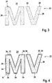
- FIG. 3 shows the in FIG. 2 represented area A of the in-mold film 22 in an enlarged view according to a first embodiment of the in-mold film 22nd
- the in-mold foil 22 Shown is a part of the in-mold foil 22 with the first area 24 assigned to the base area 10, a second area 26 assigned to the relief element "M” and a second area 26 assigned to the relief element "V".
- a transition area 30 between the first area 24 and In the second region 26, the in-mold film 22 has a preconditioning 31 in the form of a perforation 32, which completely surrounds the two second regions 26 in each case.
- the transition region 30 can also be referred to below as an inner contour of the in-mold film 22, and is also referred to with reference to FIGS FIGS. 5 to 13 illustrated and explained in more detail.
- FIG. 4 is an enlargement of the in FIG. 2 represented region A according to another embodiment of the in-mold film 22.
- the in-mold film 22 has a first area 24 assigned to the base area 10 and two second areas 26 assigned to the relief elements 20.
- the in-mold film 22 has a plurality of preconditioning 31 in the form of cuts 34, wherein in the illustrated embodiment for the relief element "M” a total of five cuts 34 are provided and for the Relief element "V" a total of three sections 34.
- the in FIG. 4 shown preconditioning 31 may in other embodiments also punched, punched or z. B. Ausspanept.
- FIG. 5 shows an enlarged detail of the area B from FIG. 4 at one foot of the relief element "M".
- the first region 24 is connected to the second region 26 via the web 36, so that the in-mold film 22 is in one piece.
- On the side of the web 36 are two preconditionings 31, which are designed as cuts 34 as described.
- the transition region 30 between the first region 24 and the second region 26 is formed by the web 36 and the preconditioning 31.
- the transition region 30 has a thickness d 1 .
- the web 36 has a web width d 2 .
- FIG. 6 shows a sectional view through the in FIG. 1 represented line C - C, ie through the center of the relief element "M". Shown is a section through the container base body 4 and through the inmould foil 22 arranged thereon. The size ratios are not reproduced to scale in order to facilitate understanding.
- the in-mold film 22 has a first region 24, which covers the base surface 10 of the container base body 4.
- the in-mold film 22 has a second region 26, which covers the relief element 20. Furthermore, the in-mold film 22 comprises two transition regions 30 between the first region 24 and the second region 26.
- the in FIG. 4 For example, shown on the left first transition region 30 has a well-defined compensation recess 23 which is formed as an opening 25.
- the opening 25 is for example the product of one of the with respect to FIGS. 3 to 5 described preconditioning 31 after injection molding.
- the in-mold film 22 has the web 36, which further connects the first region 24 with the second region 26 with each other.
- the relief element 20 has a height d 6 .
- the length of the web 36, ie the width d 1 of the transition region 30, corresponds to the height d 6 of the relief element 20, except for the distortion caused by the pressure during injection molding.
- the in-mold film 22 comprises four layers in the illustrated embodiment, wherein at least partially a first printing layer 44 is arranged on the side 40 facing the container base 4. Above the first printing layer 44 is a base film 46 forming the second layer, which is at least partially covered by a second printing layer 48 forming the third layer. On the side facing away from the container body 4 side 42 of the in-mold film 22 is a cover layer 50, which may be, for example, a paint and / or a lamination.
- FIG. 7 shows an alternative embodiment to that with reference to FIG. 1 and 6 described embodiment of the invention, in which case the "M" is formed as an inverted relief element 21.
- the container body 4 comprises the Base 10 and recessed relative to the base 10 trained, inverted relief element 21, for example, the letter “M” forms.
- the depth of the inverted relief element is represented by d 7 .
- the inmold film 22 comprises, as related to FIG. 6 already described, the first region 24 and the second region 26, and corresponding transition regions 30 which connect the first and second regions 24, 26 with each other. In the transition area 30 shown on the left, the well-defined compensation recess 23 is formed through the opening 25 and the transition region 30 shown on the right is the web 36.
- the in-mold film 22 includes, as with reference to FIG. 6 described, a four-layer structure, wherein the container base body 4 facing side 40 comprises a first pressure layer 44 and the container base body 4 opposite side 42, the cover layer 50th
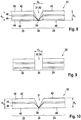
- FIG. 8 shows a sectional view of a portion of an in-mold film 22 with representation of the first region 24, the transition region 30 and the second region 26 before it was placed on the container base 4 (here and in the following not shown) and back-injected, ie an Inmoud film 22, the z. B. is still supplied to the injection molding tool.
- the in-mold film 22 has a preconditioning 31 formed as a region 52 with a reduced thickness.
- the region 52 of reduced thickness is formed here by a stamping, wherein the punched-through the in-mold film 22 was not cut as in a punching in two parts, but has a film hinge 38, which is here for example in the middle of the transition region 30 is present ,
- the film hinge 38 is provided on the container base body 4 facing side 40.
- the film hinge 38 may be provided on the side facing away from the container base body 4 42, wherein the punching takes place from the corresponding side.
- the in-mold foil 22 comprises the ones with reference to FIGS. 6 and 7 described layer sequence with the container base body 4 facing first printing layer 44, followed by the base film 46, the second printing layer 48 and the container base body 4 facing away from cover layer 50.
- the in-mold film 22 has in its second region 26 has a thickness d 3 and in its first Range a thickness d 4 , wherein the thicknesses d 3 and d 4 here, for example, and are typically the same.
- FIG. 9 shows an in-mold film 22 according to an alternative embodiment, wherein as in FIG. 8 the first region 24, the transition region 30 and the second region 26 are shown.
- the in-mold film 22 has a preconditioning 31 formed as an opening 54, which may be, for example, a cut 34 or a perforation 32.
- FIG. 10 shows an in-mold film 22 according to an alternative embodiment, wherein the in-mold film 22 comprises three layers.
- the base film 46 On the side of the inmould film 22 facing the container base 4, there is the base film 46, which is covered by the second printing layer 48.
- the cover layer 50 On the side facing away from the container base body 4 42 is the cover layer 50, which may be, for example, a paint and / or a lamination.
- the in-mold film 22 is otherwise formed as described above and comprises the film hinge 38 in the transition region 30 in the illustrated embodiment.
- FIG. 11 shows a double film 64 with two superimposed in-mold films 22-1, 22-1, wherein as in FIGS. 8 to 10 corresponding to the first region 24, the second region 26 and the transition region 30 are shown.
- the two in-mold films 22-1, 22-2 lie flat against each other, with a first in-mold film 22-1 facing the container base 4 and a second in-mold film 22-2 facing away from the container base 4 (or will be ).
- Both inmould films 22 - 1, 22 - 2 have the preconditioning 31 in the transition region 30, this in turn comprising the film hinge 38, which is located on the side 40 facing the container base body 4.
- Both in-mold films 22-1, 22-2 comprise in the illustrated embodiment, the same four-layer structure, which with reference to the FIGS.
- the second inmould foil 22-2 is shortened in the first region 24 and lies there only partially on the first inmould foil 22-1.
- the in-mold films 22-1, 22-2 thus have an overlap region 60 and in the first region 24 a single film region 62, which is formed only by the first in-mold film 22-1.
- the double film 64 has a thickness d 8 and in the individual film area 62 a thickness d 9 .
- FIG. 12 shows an alternative embodiment of a double sheet 64 comprising two in-mold sheets 22-1, 22-2, wherein the first in-mold sheet 22-1 is one with reference to FIGS FIGS. 6 to 9 described four-layer in-mold film 22 and wherein the second inmold film 22-2 is one with reference to FIG. 10 described three-layer Inmauld foil 22 is.
- the double film 64 comprises the film hinge 38 forming the well-defined compensation recess 23.
- the second inmould film 58 does not completely cover the first inmould film 56.
- the overlapping area 60 is provided only in a part of the second area 26, ie on a part of the relief element 20 or inverted relief element 21, and in the base area 10 the single foil area 62 is present.
- FIG. 13 shows a further embodiment of the double sheet 64, wherein, as with reference to FIG. 12 described, the first in-mold film 22-1 is formed as a four-layer in-mold film 22 and the second in-mold film 22-2 is formed as a three-layer in-mold film 22.
- the well-defined compensation recess 23 is formed as a film hinge 38.
- the overlapping area 60 is only provided exactly in the second area 26, ie on the relief element 20 or inverted relief element 21, so that the single-foil area 62 is present in the base area 10
- first in-mold film 22-1 is made matt and the second in-mold film 22-2 high gloss or vice versa.
- inventions may also comprise double films 64, wherein both in-mold films 22-1, 22-2 are formed as three-layer in-mold films 22 or wherein the first inmould film 22-1 facing the container main body 4 has a three-layered structure Inmould foil 22 and the second inmould foil 22-2 facing away from the container base body 4 is a four-layer inmould foil 22.
- FIG. 14 shows an injection molding machine 100, by means of which a transport container according to the invention can be produced.
- the injection molding machine 100 comprises an injection molding tool 110, in which an in-mold film 22 is back-injected from the plastic forming the container body.
- the injection molding tool 110 is coupled to a first vacuum system 112 which is adapted to apply one or more vacuums to a tool jaw (not shown) of the injection molding tool 110 in order to apply the used inmould foil 22 to hold as a whole or with island areas in position.
- the injection molding machine 100 also includes a robot device 120 with, for example, a robot arm 122, which has a manipulation head 126 which can be freely positioned in the space by means of joints 130.
- a camera 124 is attached to the robotic device 120 and is equipped with appropriate software for recognizing printings 29 and preconditioning 31, such as outer contours 28 of the in-mold films 22, or for detecting the position of the in-mold film 22.
- the manipulating head 126 also includes a suction device 128 connected to a second vacuum system 132 for generating vacuum along vacuum edges. By means of the suction device 128, the manipulating head 126 can singulate the in-mold foils 22 and insert them into the tool jaw of the injection molding tool 110 for subsequent back-injection.
- the inmould films 22 are initially in a wound form on a roll 136, i. are supplied to the injection molding tool 110 in the illustrated embodiment as a rolled product.
- the feeder 134 unrolls the roller 136. It here comprises a series of conveyor rollers 138, which is only one of many possibilities known to those skilled in the art.
- FIG. 14 Furthermore, a pair of rollers with two interlocking structured rollers 140 is shown, through which the in-mold films 22 are guided, and which produces a structuring on the in-mold films 22, which corresponds to a matt effect.
- the injection molding tool 110, the robotic device 120, the vacuum equipment 112, 132, and the feeder 134 are connected to a central controller 150 which coordinates the individual processes.
- the central controller 150 can effect a precise transfer and positioning of the inmould film 22 in the injection molding tool 110.
Landscapes
- Engineering & Computer Science (AREA)
- Manufacturing & Machinery (AREA)
- Mechanical Engineering (AREA)
- Moulds For Moulding Plastics Or The Like (AREA)
Priority Applications (1)
| Application Number | Priority Date | Filing Date | Title |
|---|---|---|---|
| EP18159712.1A EP3533582B1 (fr) | 2018-03-02 | 2018-03-02 | Récipient de transport pourvu de film dans le moule |
Applications Claiming Priority (1)
| Application Number | Priority Date | Filing Date | Title |
|---|---|---|---|
| EP18159712.1A EP3533582B1 (fr) | 2018-03-02 | 2018-03-02 | Récipient de transport pourvu de film dans le moule |
Publications (2)
| Publication Number | Publication Date |
|---|---|
| EP3533582A1 true EP3533582A1 (fr) | 2019-09-04 |
| EP3533582B1 EP3533582B1 (fr) | 2020-11-25 |
Family
ID=61557188
Family Applications (1)
| Application Number | Title | Priority Date | Filing Date |
|---|---|---|---|
| EP18159712.1A Active EP3533582B1 (fr) | 2018-03-02 | 2018-03-02 | Récipient de transport pourvu de film dans le moule |
Country Status (1)
| Country | Link |
|---|---|
| EP (1) | EP3533582B1 (fr) |
Cited By (2)
| Publication number | Priority date | Publication date | Assignee | Title |
|---|---|---|---|---|
| WO2021119957A1 (fr) * | 2019-12-16 | 2021-06-24 | 苏州信运比尔精密机械有限公司 | Dispositif de moulage intégré pour pièce à travailler |
| CN115916503A (zh) * | 2019-12-13 | 2023-04-04 | 法雷奥照明公司 | 车辆照明装置的具有成角度的部分的元件 |
Citations (3)
| Publication number | Priority date | Publication date | Assignee | Title |
|---|---|---|---|---|
| DE69126109T2 (de) * | 1990-12-28 | 1997-10-16 | Nippla Co Ltd | In der Form etikettierter Behälter mit länglichem hervorstehendem Teil des Bodens und Verfahren zu seiner Herstellung |
| EP2554485A1 (fr) | 2011-08-02 | 2013-02-06 | Oberland M & V GmbH | Caisse à bouteilles dotée d'une feuille à relief |
| US20150024156A1 (en) * | 2013-07-17 | 2015-01-22 | Modern Packaging | In-mold label forming surfaces for molded articles |
-
2018
- 2018-03-02 EP EP18159712.1A patent/EP3533582B1/fr active Active
Patent Citations (3)
| Publication number | Priority date | Publication date | Assignee | Title |
|---|---|---|---|---|
| DE69126109T2 (de) * | 1990-12-28 | 1997-10-16 | Nippla Co Ltd | In der Form etikettierter Behälter mit länglichem hervorstehendem Teil des Bodens und Verfahren zu seiner Herstellung |
| EP2554485A1 (fr) | 2011-08-02 | 2013-02-06 | Oberland M & V GmbH | Caisse à bouteilles dotée d'une feuille à relief |
| US20150024156A1 (en) * | 2013-07-17 | 2015-01-22 | Modern Packaging | In-mold label forming surfaces for molded articles |
Cited By (2)
| Publication number | Priority date | Publication date | Assignee | Title |
|---|---|---|---|---|
| CN115916503A (zh) * | 2019-12-13 | 2023-04-04 | 法雷奥照明公司 | 车辆照明装置的具有成角度的部分的元件 |
| WO2021119957A1 (fr) * | 2019-12-16 | 2021-06-24 | 苏州信运比尔精密机械有限公司 | Dispositif de moulage intégré pour pièce à travailler |
Also Published As
| Publication number | Publication date |
|---|---|
| EP3533582B1 (fr) | 2020-11-25 |
Similar Documents
| Publication | Publication Date | Title |
|---|---|---|
| EP0960024B1 (fr) | Procede de production d'elements de couvercle partiellement estampes pour recipients, dispositif d'application de la methode et element de couvercle partiellement estampe produit par la methode | |
| DE102009056169A1 (de) | Verfahren zum Zurichten von Werkzeugen | |
| EP1791765A1 (fr) | Couvercle, notamment pour un emballage alimentaire, ou tiquette, notamment pour un col de bouteille | |
| DE69622306T2 (de) | Mehrschichtiger Kunststoffgegenstand und Verfahren zu seiner Herstellung | |
| DE102012017636A1 (de) | Verfahren zum Bestimmen des Zurichtbedarfs und Verfahren zum Erstellen eines Zurichtbogens | |
| DE102015203931A1 (de) | Verfahren zur Registerkorrektur einer Flachbettstanzmaschine | |
| EP0833717B1 (fr) | Procede et dispositif pour perforer ou decouper des materiaux composites stratifies imprimes | |
| EP3533582B1 (fr) | Récipient de transport pourvu de film dans le moule | |
| EP2700511B1 (fr) | Procédé de fabrication de plaques revêtues des deux côtés avec du papier décoratif et papier décoratif pour la fabrication de telles plaques | |
| DE102008033799A1 (de) | Verfahren und Einrichtung zum Herstellen von etikettierten, foliengeformten Behältern, insbesondere zum In-Mold-Etikettieren von foliengeformten Behältern, Etikett hierfür und etikettierter Behälter | |
| EP3880561B1 (fr) | Dispositif et procédé de fabrication d'un groupe de récipients | |
| EP2554485B1 (fr) | Caisse à bouteilles dotée d'une feuille à relief | |
| EP3533581B1 (fr) | Procédé de travail d'une installation de moulage par injection et procédé de fabrication d'un récipient de transport | |
| DE10134814A1 (de) | Vorrichtung zum Überprüfen von Produkten mit Etiketts | |
| EP3600831A2 (fr) | Dispositif et procédé servant à appliquer par contrecollage un élément pelliculaire de contrecollage sur un composant, dispositif et procédé servant à appliquer de la colle, installation de contrecollage, composant destiné à être contrecollé d'un élément pelliculaire de contrecollage et utilisation d'une partie de réception servant à fournir un élément pelliculaire de contrecollage | |
| DE10196951B3 (de) | Verfahren zur Herstellung eines bedruckten Verpackungslaminats und Vorrichtung zur Durchführung des Verfahrens | |
| DE10004593C1 (de) | Verfahren und Vorrichtung zur Herstellung von Platinen für Kraftfahrzeug-Nummernschildern | |
| EP3321097B1 (fr) | Dispositif et procédé d'estampage de feuilles multifonction | |
| EP3967512B1 (fr) | Dispositif d'estampage de feuilles | |
| DE102004063348A1 (de) | Getränkekistenversiegelung | |
| DE4314346A1 (de) | Verfahren zur Bereitstellung von einzelnen Etiketten und zur Zuführung dieser Etiketten zu Formteilen | |
| EP4212350B1 (fr) | Installation de production pour la production de documents d'identité, de valeur ou de sécurité ou pour la production d'un ensemble d'une pluralité de documents d'identité, de valeur ou de sécurité | |
| DE19840981A1 (de) | Verfahren und Vorrichtung zum Herstellen bedruckter und geprägter Teile | |
| DE102017004795B4 (de) | Etikettenaufnahme | |
| DE60001436T2 (de) | Verfahren zum Öffnen eines perforierten Gegenstands |
Legal Events
| Date | Code | Title | Description |
|---|---|---|---|
| PUAI | Public reference made under article 153(3) epc to a published international application that has entered the european phase |
Free format text: ORIGINAL CODE: 0009012 |
|
| STAA | Information on the status of an ep patent application or granted ep patent |
Free format text: STATUS: THE APPLICATION HAS BEEN PUBLISHED |
|
| AK | Designated contracting states |
Kind code of ref document: A1 Designated state(s): AL AT BE BG CH CY CZ DE DK EE ES FI FR GB GR HR HU IE IS IT LI LT LU LV MC MK MT NL NO PL PT RO RS SE SI SK SM TR |
|
| AX | Request for extension of the european patent |
Extension state: BA ME |
|
| STAA | Information on the status of an ep patent application or granted ep patent |
Free format text: STATUS: REQUEST FOR EXAMINATION WAS MADE |
|
| 17P | Request for examination filed |
Effective date: 20200219 |
|
| RBV | Designated contracting states (corrected) |
Designated state(s): AL AT BE BG CH CY CZ DE DK EE ES FI FR GB GR HR HU IE IS IT LI LT LU LV MC MK MT NL NO PL PT RO RS SE SI SK SM TR |
|
| GRAP | Despatch of communication of intention to grant a patent |
Free format text: ORIGINAL CODE: EPIDOSNIGR1 |
|
| STAA | Information on the status of an ep patent application or granted ep patent |
Free format text: STATUS: GRANT OF PATENT IS INTENDED |
|
| RIC1 | Information provided on ipc code assigned before grant |
Ipc: B29C 45/14 20060101AFI20200610BHEP Ipc: B29L 31/00 20060101ALI20200610BHEP |
|
| INTG | Intention to grant announced |
Effective date: 20200630 |
|
| GRAS | Grant fee paid |
Free format text: ORIGINAL CODE: EPIDOSNIGR3 |
|
| GRAA | (expected) grant |
Free format text: ORIGINAL CODE: 0009210 |
|
| STAA | Information on the status of an ep patent application or granted ep patent |
Free format text: STATUS: THE PATENT HAS BEEN GRANTED |
|
| RIN1 | Information on inventor provided before grant (corrected) |
Inventor name: GOETZ, KIRA Inventor name: GOETZ, LISA |
|
| AK | Designated contracting states |
Kind code of ref document: B1 Designated state(s): AL AT BE BG CH CY CZ DE DK EE ES FI FR GB GR HR HU IE IS IT LI LT LU LV MC MK MT NL NO PL PT RO RS SE SI SK SM TR |
|
| REG | Reference to a national code |
Ref country code: GB Ref legal event code: FG4D Free format text: NOT ENGLISH |
|
| REG | Reference to a national code |
Ref country code: CH Ref legal event code: EP |
|
| REG | Reference to a national code |
Ref country code: AT Ref legal event code: REF Ref document number: 1337774 Country of ref document: AT Kind code of ref document: T Effective date: 20201215 |
|
| REG | Reference to a national code |
Ref country code: DE Ref legal event code: R096 Ref document number: 502018003082 Country of ref document: DE |
|
| REG | Reference to a national code |
Ref country code: IE Ref legal event code: FG4D Free format text: LANGUAGE OF EP DOCUMENT: GERMAN |
|
| REG | Reference to a national code |
Ref country code: NL Ref legal event code: MP Effective date: 20201125 |
|
| PG25 | Lapsed in a contracting state [announced via postgrant information from national office to epo] |
Ref country code: GR Free format text: LAPSE BECAUSE OF FAILURE TO SUBMIT A TRANSLATION OF THE DESCRIPTION OR TO PAY THE FEE WITHIN THE PRESCRIBED TIME-LIMIT Effective date: 20210226 Ref country code: NO Free format text: LAPSE BECAUSE OF FAILURE TO SUBMIT A TRANSLATION OF THE DESCRIPTION OR TO PAY THE FEE WITHIN THE PRESCRIBED TIME-LIMIT Effective date: 20210225 Ref country code: PT Free format text: LAPSE BECAUSE OF FAILURE TO SUBMIT A TRANSLATION OF THE DESCRIPTION OR TO PAY THE FEE WITHIN THE PRESCRIBED TIME-LIMIT Effective date: 20210325 Ref country code: RS Free format text: LAPSE BECAUSE OF FAILURE TO SUBMIT A TRANSLATION OF THE DESCRIPTION OR TO PAY THE FEE WITHIN THE PRESCRIBED TIME-LIMIT Effective date: 20201125 Ref country code: FI Free format text: LAPSE BECAUSE OF FAILURE TO SUBMIT A TRANSLATION OF THE DESCRIPTION OR TO PAY THE FEE WITHIN THE PRESCRIBED TIME-LIMIT Effective date: 20201125 |
|
| PG25 | Lapsed in a contracting state [announced via postgrant information from national office to epo] |
Ref country code: SE Free format text: LAPSE BECAUSE OF FAILURE TO SUBMIT A TRANSLATION OF THE DESCRIPTION OR TO PAY THE FEE WITHIN THE PRESCRIBED TIME-LIMIT Effective date: 20201125 Ref country code: IS Free format text: LAPSE BECAUSE OF FAILURE TO SUBMIT A TRANSLATION OF THE DESCRIPTION OR TO PAY THE FEE WITHIN THE PRESCRIBED TIME-LIMIT Effective date: 20210325 Ref country code: LV Free format text: LAPSE BECAUSE OF FAILURE TO SUBMIT A TRANSLATION OF THE DESCRIPTION OR TO PAY THE FEE WITHIN THE PRESCRIBED TIME-LIMIT Effective date: 20201125 Ref country code: PL Free format text: LAPSE BECAUSE OF FAILURE TO SUBMIT A TRANSLATION OF THE DESCRIPTION OR TO PAY THE FEE WITHIN THE PRESCRIBED TIME-LIMIT Effective date: 20201125 Ref country code: BG Free format text: LAPSE BECAUSE OF FAILURE TO SUBMIT A TRANSLATION OF THE DESCRIPTION OR TO PAY THE FEE WITHIN THE PRESCRIBED TIME-LIMIT Effective date: 20210225 |
|
| REG | Reference to a national code |
Ref country code: LT Ref legal event code: MG9D |
|
| PG25 | Lapsed in a contracting state [announced via postgrant information from national office to epo] |
Ref country code: HR Free format text: LAPSE BECAUSE OF FAILURE TO SUBMIT A TRANSLATION OF THE DESCRIPTION OR TO PAY THE FEE WITHIN THE PRESCRIBED TIME-LIMIT Effective date: 20201125 |
|
| PG25 | Lapsed in a contracting state [announced via postgrant information from national office to epo] |
Ref country code: SM Free format text: LAPSE BECAUSE OF FAILURE TO SUBMIT A TRANSLATION OF THE DESCRIPTION OR TO PAY THE FEE WITHIN THE PRESCRIBED TIME-LIMIT Effective date: 20201125 Ref country code: EE Free format text: LAPSE BECAUSE OF FAILURE TO SUBMIT A TRANSLATION OF THE DESCRIPTION OR TO PAY THE FEE WITHIN THE PRESCRIBED TIME-LIMIT Effective date: 20201125 Ref country code: CZ Free format text: LAPSE BECAUSE OF FAILURE TO SUBMIT A TRANSLATION OF THE DESCRIPTION OR TO PAY THE FEE WITHIN THE PRESCRIBED TIME-LIMIT Effective date: 20201125 Ref country code: LT Free format text: LAPSE BECAUSE OF FAILURE TO SUBMIT A TRANSLATION OF THE DESCRIPTION OR TO PAY THE FEE WITHIN THE PRESCRIBED TIME-LIMIT Effective date: 20201125 Ref country code: SK Free format text: LAPSE BECAUSE OF FAILURE TO SUBMIT A TRANSLATION OF THE DESCRIPTION OR TO PAY THE FEE WITHIN THE PRESCRIBED TIME-LIMIT Effective date: 20201125 Ref country code: RO Free format text: LAPSE BECAUSE OF FAILURE TO SUBMIT A TRANSLATION OF THE DESCRIPTION OR TO PAY THE FEE WITHIN THE PRESCRIBED TIME-LIMIT Effective date: 20201125 |
|
| REG | Reference to a national code |
Ref country code: DE Ref legal event code: R097 Ref document number: 502018003082 Country of ref document: DE |
|
| PG25 | Lapsed in a contracting state [announced via postgrant information from national office to epo] |
Ref country code: DK Free format text: LAPSE BECAUSE OF FAILURE TO SUBMIT A TRANSLATION OF THE DESCRIPTION OR TO PAY THE FEE WITHIN THE PRESCRIBED TIME-LIMIT Effective date: 20201125 |
|
| PLBE | No opposition filed within time limit |
Free format text: ORIGINAL CODE: 0009261 |
|
| STAA | Information on the status of an ep patent application or granted ep patent |
Free format text: STATUS: NO OPPOSITION FILED WITHIN TIME LIMIT |
|
| PG25 | Lapsed in a contracting state [announced via postgrant information from national office to epo] |
Ref country code: NL Free format text: LAPSE BECAUSE OF FAILURE TO SUBMIT A TRANSLATION OF THE DESCRIPTION OR TO PAY THE FEE WITHIN THE PRESCRIBED TIME-LIMIT Effective date: 20201125 Ref country code: AL Free format text: LAPSE BECAUSE OF FAILURE TO SUBMIT A TRANSLATION OF THE DESCRIPTION OR TO PAY THE FEE WITHIN THE PRESCRIBED TIME-LIMIT Effective date: 20201125 Ref country code: MC Free format text: LAPSE BECAUSE OF FAILURE TO SUBMIT A TRANSLATION OF THE DESCRIPTION OR TO PAY THE FEE WITHIN THE PRESCRIBED TIME-LIMIT Effective date: 20201125 Ref country code: IT Free format text: LAPSE BECAUSE OF FAILURE TO SUBMIT A TRANSLATION OF THE DESCRIPTION OR TO PAY THE FEE WITHIN THE PRESCRIBED TIME-LIMIT Effective date: 20201125 |
|
| REG | Reference to a national code |
Ref country code: CH Ref legal event code: PL |
|
| 26N | No opposition filed |
Effective date: 20210826 |
|
| PG25 | Lapsed in a contracting state [announced via postgrant information from national office to epo] |
Ref country code: SI Free format text: LAPSE BECAUSE OF FAILURE TO SUBMIT A TRANSLATION OF THE DESCRIPTION OR TO PAY THE FEE WITHIN THE PRESCRIBED TIME-LIMIT Effective date: 20201125 |
|
| REG | Reference to a national code |
Ref country code: BE Ref legal event code: MM Effective date: 20210331 |
|
| PG25 | Lapsed in a contracting state [announced via postgrant information from national office to epo] |
Ref country code: CH Free format text: LAPSE BECAUSE OF NON-PAYMENT OF DUE FEES Effective date: 20210331 Ref country code: LI Free format text: LAPSE BECAUSE OF NON-PAYMENT OF DUE FEES Effective date: 20210331 Ref country code: ES Free format text: LAPSE BECAUSE OF FAILURE TO SUBMIT A TRANSLATION OF THE DESCRIPTION OR TO PAY THE FEE WITHIN THE PRESCRIBED TIME-LIMIT Effective date: 20201125 Ref country code: FR Free format text: LAPSE BECAUSE OF NON-PAYMENT OF DUE FEES Effective date: 20210331 Ref country code: IE Free format text: LAPSE BECAUSE OF NON-PAYMENT OF DUE FEES Effective date: 20210302 Ref country code: LU Free format text: LAPSE BECAUSE OF NON-PAYMENT OF DUE FEES Effective date: 20210302 |
|
| REG | Reference to a national code |
Ref country code: DE Ref legal event code: R082 Ref document number: 502018003082 Country of ref document: DE Representative=s name: SIMMONS & SIMMONS LLP, DE |
|
| PG25 | Lapsed in a contracting state [announced via postgrant information from national office to epo] |
Ref country code: IS Free format text: LAPSE BECAUSE OF FAILURE TO SUBMIT A TRANSLATION OF THE DESCRIPTION OR TO PAY THE FEE WITHIN THE PRESCRIBED TIME-LIMIT Effective date: 20210325 |
|
| PG25 | Lapsed in a contracting state [announced via postgrant information from national office to epo] |
Ref country code: BE Free format text: LAPSE BECAUSE OF NON-PAYMENT OF DUE FEES Effective date: 20210331 |
|
| GBPC | Gb: european patent ceased through non-payment of renewal fee |
Effective date: 20220302 |
|
| PG25 | Lapsed in a contracting state [announced via postgrant information from national office to epo] |
Ref country code: GB Free format text: LAPSE BECAUSE OF NON-PAYMENT OF DUE FEES Effective date: 20220302 |
|
| PG25 | Lapsed in a contracting state [announced via postgrant information from national office to epo] |
Ref country code: CY Free format text: LAPSE BECAUSE OF FAILURE TO SUBMIT A TRANSLATION OF THE DESCRIPTION OR TO PAY THE FEE WITHIN THE PRESCRIBED TIME-LIMIT Effective date: 20201125 |
|
| PG25 | Lapsed in a contracting state [announced via postgrant information from national office to epo] |
Ref country code: HU Free format text: LAPSE BECAUSE OF FAILURE TO SUBMIT A TRANSLATION OF THE DESCRIPTION OR TO PAY THE FEE WITHIN THE PRESCRIBED TIME-LIMIT; INVALID AB INITIO Effective date: 20180302 |
|
| P01 | Opt-out of the competence of the unified patent court (upc) registered |
Effective date: 20230824 |
|
| PG25 | Lapsed in a contracting state [announced via postgrant information from national office to epo] |
Ref country code: MK Free format text: LAPSE BECAUSE OF FAILURE TO SUBMIT A TRANSLATION OF THE DESCRIPTION OR TO PAY THE FEE WITHIN THE PRESCRIBED TIME-LIMIT Effective date: 20201125 |
|
| REG | Reference to a national code |
Ref country code: AT Ref legal event code: MM01 Ref document number: 1337774 Country of ref document: AT Kind code of ref document: T Effective date: 20230302 |
|
| PG25 | Lapsed in a contracting state [announced via postgrant information from national office to epo] |
Ref country code: AT Free format text: LAPSE BECAUSE OF NON-PAYMENT OF DUE FEES Effective date: 20230302 |
|
| PG25 | Lapsed in a contracting state [announced via postgrant information from national office to epo] |
Ref country code: AT Free format text: LAPSE BECAUSE OF NON-PAYMENT OF DUE FEES Effective date: 20230302 |
|
| PG25 | Lapsed in a contracting state [announced via postgrant information from national office to epo] |
Ref country code: MT Free format text: LAPSE BECAUSE OF FAILURE TO SUBMIT A TRANSLATION OF THE DESCRIPTION OR TO PAY THE FEE WITHIN THE PRESCRIBED TIME-LIMIT Effective date: 20201125 |
|
| PG25 | Lapsed in a contracting state [announced via postgrant information from national office to epo] |
Ref country code: TR Free format text: LAPSE BECAUSE OF FAILURE TO SUBMIT A TRANSLATION OF THE DESCRIPTION OR TO PAY THE FEE WITHIN THE PRESCRIBED TIME-LIMIT Effective date: 20201125 |
|
| PGFP | Annual fee paid to national office [announced via postgrant information from national office to epo] |
Ref country code: DE Payment date: 20260115 Year of fee payment: 9 |
|
| PGFP | Annual fee paid to national office [announced via postgrant information from national office to epo] |
Ref country code: AT Payment date: 20260410 Year of fee payment: 5 |