EP3533957A2 - Châssis de guidage de porte de structure à segments démontables pour fenêtres et portes coulissantes - Google Patents
Châssis de guidage de porte de structure à segments démontables pour fenêtres et portes coulissantes Download PDFInfo
- Publication number
- EP3533957A2 EP3533957A2 EP17865977.7A EP17865977A EP3533957A2 EP 3533957 A2 EP3533957 A2 EP 3533957A2 EP 17865977 A EP17865977 A EP 17865977A EP 3533957 A2 EP3533957 A2 EP 3533957A2
- Authority
- EP
- European Patent Office
- Prior art keywords
- main body
- guide frame
- body portion
- door guide
- Prior art date
- Legal status (The legal status is an assumption and is not a legal conclusion. Google has not performed a legal analysis and makes no representation as to the accuracy of the status listed.)
- Granted
Links
Images


Classifications
-
- E—FIXED CONSTRUCTIONS
- E05—LOCKS; KEYS; WINDOW OR DOOR FITTINGS; SAFES
- E05D—HINGES OR SUSPENSION DEVICES FOR DOORS, WINDOWS OR WINGS
- E05D15/00—Suspension arrangements for wings
- E05D15/06—Suspension arrangements for wings for wings sliding horizontally more or less in their own plane
- E05D15/0621—Details, e.g. suspension or supporting guides
- E05D15/066—Details, e.g. suspension or supporting guides for wings supported at the bottom
- E05D15/0682—Details, e.g. suspension or supporting guides for wings supported at the bottom on sliding blocks
-
- E—FIXED CONSTRUCTIONS
- E06—DOORS, WINDOWS, SHUTTERS, OR ROLLER BLINDS IN GENERAL; LADDERS
- E06B—FIXED OR MOVABLE CLOSURES FOR OPENINGS IN BUILDINGS, VEHICLES, FENCES OR LIKE ENCLOSURES IN GENERAL, e.g. DOORS, WINDOWS, BLINDS, GATES
- E06B3/00—Window sashes, door leaves, or like elements for closing wall or like openings; Layout of fixed or moving closures, e.g. windows in wall or like openings; Features of rigidly-mounted outer frames relating to the mounting of wing frames
- E06B3/32—Arrangements of wings characterised by the manner of movement; Arrangements of movable wings in openings; Features of wings or frames relating solely to the manner of movement of the wing
- E06B3/34—Arrangements of wings characterised by the manner of movement; Arrangements of movable wings in openings; Features of wings or frames relating solely to the manner of movement of the wing with only one kind of movement
- E06B3/42—Sliding wings; Details of frames with respect to guiding
- E06B3/46—Horizontally-sliding wings
-
- E—FIXED CONSTRUCTIONS
- E06—DOORS, WINDOWS, SHUTTERS, OR ROLLER BLINDS IN GENERAL; LADDERS
- E06B—FIXED OR MOVABLE CLOSURES FOR OPENINGS IN BUILDINGS, VEHICLES, FENCES OR LIKE ENCLOSURES IN GENERAL, e.g. DOORS, WINDOWS, BLINDS, GATES
- E06B3/00—Window sashes, door leaves, or like elements for closing wall or like openings; Layout of fixed or moving closures, e.g. windows in wall or like openings; Features of rigidly-mounted outer frames relating to the mounting of wing frames
- E06B3/04—Wing frames not characterised by the manner of movement
- E06B3/263—Frames with special provision for insulation
- E06B3/26347—Frames with special provision for insulation specially adapted for sliding doors or windows
-
- E—FIXED CONSTRUCTIONS
- E05—LOCKS; KEYS; WINDOW OR DOOR FITTINGS; SAFES
- E05D—HINGES OR SUSPENSION DEVICES FOR DOORS, WINDOWS OR WINGS
- E05D15/00—Suspension arrangements for wings
- E05D15/06—Suspension arrangements for wings for wings sliding horizontally more or less in their own plane
- E05D15/0621—Details, e.g. suspension or supporting guides
- E05D15/066—Details, e.g. suspension or supporting guides for wings supported at the bottom
- E05D15/0686—Tracks
-
- E—FIXED CONSTRUCTIONS
- E05—LOCKS; KEYS; WINDOW OR DOOR FITTINGS; SAFES
- E05D—HINGES OR SUSPENSION DEVICES FOR DOORS, WINDOWS OR WINGS
- E05D15/00—Suspension arrangements for wings
- E05D15/06—Suspension arrangements for wings for wings sliding horizontally more or less in their own plane
- E05D15/08—Suspension arrangements for wings for wings sliding horizontally more or less in their own plane consisting of two or more independent parts movable each in its own guides
-
- E—FIXED CONSTRUCTIONS
- E06—DOORS, WINDOWS, SHUTTERS, OR ROLLER BLINDS IN GENERAL; LADDERS
- E06B—FIXED OR MOVABLE CLOSURES FOR OPENINGS IN BUILDINGS, VEHICLES, FENCES OR LIKE ENCLOSURES IN GENERAL, e.g. DOORS, WINDOWS, BLINDS, GATES
- E06B3/00—Window sashes, door leaves, or like elements for closing wall or like openings; Layout of fixed or moving closures, e.g. windows in wall or like openings; Features of rigidly-mounted outer frames relating to the mounting of wing frames
- E06B3/04—Wing frames not characterised by the manner of movement
- E06B3/263—Frames with special provision for insulation
-
- E—FIXED CONSTRUCTIONS
- E06—DOORS, WINDOWS, SHUTTERS, OR ROLLER BLINDS IN GENERAL; LADDERS
- E06B—FIXED OR MOVABLE CLOSURES FOR OPENINGS IN BUILDINGS, VEHICLES, FENCES OR LIKE ENCLOSURES IN GENERAL, e.g. DOORS, WINDOWS, BLINDS, GATES
- E06B3/00—Window sashes, door leaves, or like elements for closing wall or like openings; Layout of fixed or moving closures, e.g. windows in wall or like openings; Features of rigidly-mounted outer frames relating to the mounting of wing frames
- E06B3/32—Arrangements of wings characterised by the manner of movement; Arrangements of movable wings in openings; Features of wings or frames relating solely to the manner of movement of the wing
- E06B3/34—Arrangements of wings characterised by the manner of movement; Arrangements of movable wings in openings; Features of wings or frames relating solely to the manner of movement of the wing with only one kind of movement
- E06B3/42—Sliding wings; Details of frames with respect to guiding
- E06B3/46—Horizontally-sliding wings
- E06B3/4609—Horizontally-sliding wings for windows
-
- E—FIXED CONSTRUCTIONS
- E06—DOORS, WINDOWS, SHUTTERS, OR ROLLER BLINDS IN GENERAL; LADDERS
- E06B—FIXED OR MOVABLE CLOSURES FOR OPENINGS IN BUILDINGS, VEHICLES, FENCES OR LIKE ENCLOSURES IN GENERAL, e.g. DOORS, WINDOWS, BLINDS, GATES
- E06B9/00—Screening or protective devices for wall or similar openings, with or without operating or securing mechanisms; Closures of similar construction
- E06B9/52—Devices affording protection against insects, e.g. fly screens; Mesh windows for other purposes
-
- E—FIXED CONSTRUCTIONS
- E05—LOCKS; KEYS; WINDOW OR DOOR FITTINGS; SAFES
- E05D—HINGES OR SUSPENSION DEVICES FOR DOORS, WINDOWS OR WINGS
- E05D15/00—Suspension arrangements for wings
- E05D15/06—Suspension arrangements for wings for wings sliding horizontally more or less in their own plane
-
- E—FIXED CONSTRUCTIONS
- E05—LOCKS; KEYS; WINDOW OR DOOR FITTINGS; SAFES
- E05Y—INDEXING SCHEME ASSOCIATED WITH SUBCLASSES E05D AND E05F, RELATING TO CONSTRUCTION ELEMENTS, ELECTRIC CONTROL, POWER SUPPLY, POWER SIGNAL OR TRANSMISSION, USER INTERFACES, MOUNTING OR COUPLING, DETAILS, ACCESSORIES, AUXILIARY OPERATIONS NOT OTHERWISE PROVIDED FOR, APPLICATION THEREOF
- E05Y2900/00—Application of doors, windows, wings or fittings thereof
- E05Y2900/10—Application of doors, windows, wings or fittings thereof for buildings or parts thereof
- E05Y2900/13—Type of wing
- E05Y2900/132—Doors
-
- E—FIXED CONSTRUCTIONS
- E05—LOCKS; KEYS; WINDOW OR DOOR FITTINGS; SAFES
- E05Y—INDEXING SCHEME ASSOCIATED WITH SUBCLASSES E05D AND E05F, RELATING TO CONSTRUCTION ELEMENTS, ELECTRIC CONTROL, POWER SUPPLY, POWER SIGNAL OR TRANSMISSION, USER INTERFACES, MOUNTING OR COUPLING, DETAILS, ACCESSORIES, AUXILIARY OPERATIONS NOT OTHERWISE PROVIDED FOR, APPLICATION THEREOF
- E05Y2900/00—Application of doors, windows, wings or fittings thereof
- E05Y2900/10—Application of doors, windows, wings or fittings thereof for buildings or parts thereof
- E05Y2900/13—Type of wing
- E05Y2900/148—Windows
Definitions
- the present invention relates to a door guide frame of detachable segment structure for guiding the sliding movement of a roller device which supports a sliding window and provides a sliding opening/closing operation and, more particularly, to a sliding window installation structure which is capable of: stably supporting and moving a sliding window or a horizontal sliding window (hereinafter, generally referred to as a "sliding window") on a bottom surface and a top surface on which the sliding window is installed; reducing an installation space by minimizing the size of a door guide frame and a roller device for supporting a heavy sliding window, thereby obtaining a wider open view when applied to a window; and employing a structure comprising a door guide frame of detachable segment structure which prevents a door guide rail from protruding upward from the bottom surface of a window frame so as to prevent occurrence of a passage obstacle which may be caused when the door guide rail protrudes on a moving passage while the window is opened, as well as to provide a good aesthetic appearance, thereby providing excellent applic
- Korean Patent Application No. 10-2012-0047789 filed on May 26, 2012
- a sliding window installation structure including a door guide frame of such a separable and detachable segment structure.
- This Korean patent application has been disclosed in Korean Patent Laid-Open Publication No. 10-2013-0124444 (published on November 14, 2013 ) and Korean Patent Publication No. 10-1367835 (issued on March 03, 2014 ) It has also been published as WIPO Open Publication WO2013 / 168943A1 (published Nov. 14, 2014 ) and US Patent Application Laid-Open No. 2015-0121764 A1 (published May 7, 2015 ).
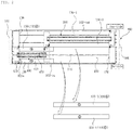
- a door guide frame 100 for guiding a sliding window 400 at the inner and outer sides (front side and back side / inner and outer surfaces) of the sliding window 400, in which a pocket guide 130 is detachably attached to a main body portion 120 of the door guide frame 100.
- the pocket guide 130 includes a pocket guide segment (130; 130a or 130b; 130-1, 130-2, 130-3, and 130-4) detachable from the main body portion 120 of the door guide frame 100.
- the door guide frame 100 having a structure in which the pocket guide segments (130; 130a or 130b) are detachably and continuously installed on both inner and outer surfaces of the sliding window 400 along a moving direction of a roller guide rail 110.
- an aluminum material can be generally used as a basic material for providing the door guide frame 100 having a detachable segment structure that forms such a structure.
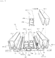
- FIG. 2 a partially exploded perspective view of FIG. 2 (a perspective view at a B-B' broken line location of FIG.
- a leg region 130m may be preferably formed of a heat-transmission-blocking material separated from a remaining upper cap region 130a made of aluminum.
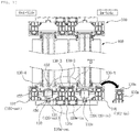
- main body portion 120 of the door guide frame 100 is arranged into two parts of an outer main body portion 120-out and an inner main body portion 120-in while the heat bridge blocking member 120m is disposed in the middle of the two parts as shown in FIG 5 .
- four pocket guide segments (130: 130a or 130b; 130-1, 130-2, 130-3, and 130-4) should be detachably installed on the main body portion 120 of the door guide frame 100, i.e. on the base surfaces of the outer main body portion 120-out and the inner main body portion 120-in.
- a partition wall 121 is protruded and formed on both sides of the roller guide rail 110 along the moving direction of the roller guide rail 110 to form a receiving portion 122 into which the pocket guide segment 130 can be inserted.
- a leg portion of a first pocket guide segment 130-1 is inserted into an inner side of the receiving portion 122 of the inner main body portion 120-in
- a leg portion of a second pocket guide segment 130-2 is inserted into an outer side of the receiving portion 122 of the inner main body portion 120-in
- a leg portion of a third pocket guide segment 130-3 is inserted into an inner side of the receiving portion 122 of the outer main body portion 120-out
- a leg portion of a fourth pocket guide segment 130-4 is received into an outer side of the receiving portion 122 of the outer main body portion 120-out, respectively.
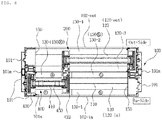
- FIGS. 6 , 7 and 8 show an application example in which the structure shown in FIGS. 1 to 4 and 5 is designed and manufactured as an actual product.
- a vertical guide frame 101 on both sides is also made to adopt a heat insulating structure in which an inner frame and an outer frame are connected to each other by a thermal bridge blocking member 101m disposed in the middle region between the inner frame and the outer frame, and in a vertical reinforcing member 420 having an enlarged section (a section having a thickness larger than a thickness of the glass) for compensating the lateral bending stiffness of the glass 410 is formed on both sides of a glass 410 constituting the sliding window 400, furthermore provides a specific difference in that a steel reinforcing plate 422 for reinforcing the rigidity is inserted into the inside of the vertical reinforcing member 420.
- the entirety may be formed of an aluminum material (see FIG. 5 ), or only the leg portion thereof may be formed as a thermal bridge blocking member (see Fig. 6 and Fig. 7 ).
- the present invention has been made in order to solve the problems in the prior art and a technical object of the present invention is to provide a means for providing a good supporting force for a lower leg region formed of such a heat bridge blocking member without damaging the heat insulating performance of the frame, even when the second pocket guide segment accommodated in the outer side surface of the inner main body portion and the third pocket guide segment accommodated in the inner side surface of the outer main body portion is separated from the upper cap region of the aluminum material and has the lower leg region formed of the heat bridge blocking member, in order to improve the heat insulating performance of the door guide frame, the door guide frame of the detachable and detachable segment structure for sliding windows is divided into an outer main body portion, an main inner body portion, and a heat bridge blocking member between thereof.
- the present invention provides door guide frame of the segmented structure for sliding windows and doors; in the door guide frame, a pocket guide being detachably attached to a main body portion of the door guide frame, wherein the pocket guide which is laterally guided and supported on both the inner and outer sides of the sliding window is detachably installed from the main body portion of the door guide frame; the pocket guide is formed as a pocket guide segment that is detachable from the main body portion of the door guide frame; and the pocket guide segments are mutually removably installed on both the inner and outer sides of the sliding window along the traveling direction of the roller guide rail; wherein, in a door guide frame of a separable and detachable segment structure for sliding windows and doors, in which the door guide frame is divided into an outer main body portion and an inner main body portion, a thermal bridge blocking member is disposed in the middle (between the outer main body portion and the inner main body portion), a second pocket guide segment being received in an outer surface of the inner main body portion and
- a vertical guide frame is provided in a vertical direction on both side surfaces of the main body of the door guide frame constituting the door guide frame, and the vertical guide frame is divided into an outer vertical guide frame and an inner vertical guide frame. Additionally it is possible to provide a structure in which the outer heat bridge blocking member (the outer heat bridge blocker), the connector, and the inner heat bridge blocking member (the inner heat bridge blocker) are arranged and connected between thereof.
- an insect-proof window mounting frame is additionally provided on an outer front surface of the door guide frame, and an extended outer surface extending outwardly from the outer main body portion forming the guide frame main body portion of the door guide frame, and therefore a fastening groove for the insect-proof window mounting frame may be provided on at least one outer surface of an outer surface of the outer vertical guide frame of the vertical guide frame and a extended outer surface extended from an outer surface of the outer main body forming the main body of the guide frame of the door guide frame.
- the second pocket guide segment accommodated in the outer surface of the inner main body portion and the third pocket guide segment accommodated in the inner surface of the outer main body portion are separated from the upper cap region of the aluminum material, and the intermediate connector in which the separator for separating and supporting the lower leg region formed of the heat bridge blocking member is formed without damaging the heat insulating performance of the door guide frame is provided between the external heat bridge blocking member and the internal heat bridge blocking member so that it is possible to provide a good supporting force.
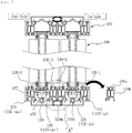
- FIG. 9 , 10 , and 11 are cross-sectional views of an installation state of a preferred embodiment of a sliding window installation structure (a sliding window installation structure including a door guide frame of a separable and detachable segment structure) according to the basic concept of the present invention are shown, and according to a preferred embodiment of the present invention illustrated through these figures, As shown in FIG.
- a pocket guide 130 being detachably attached to a main body portion 120 of the door guide frame 100, wherein the pocket guide 130 which is laterally guided and supported on both the inner and outer sides of the sliding window is detachably installed from the main body portion 120 of the door guide frame 100;
- the pocket guide 130 is formed as a pocket guide segment (130: 130a or 130b) that is detachable from the main body portion 120 of the door guide frame 100;
- the pocket guide segments (130: 130a or 130b) are mutually removably installed on both the inner and outer sides of the sliding window along the traveling direction of the roller guide rail 110;
- the door guide frame 100 of a separable and detachable segment structure comprising; in order to improve the heat insulation performance of the door guide frame, an external heat bridge blocking member 120m-out, one side of which is coupled to an inner side surface of the outer main body portion 120-out, and an internal heat bridge blocking member 120m-in, one side of which is coupled to an external side surface of the inner main body portion 120-in; and an intermediate connector 120c of aluminum material having both side surfaces joined to the other side surfaces of the external heat bridge blocking member 120m-out and the internal heat bridge blocking member 120m-in; and wherein, the door guide frame of a separable and detachable segment structure being characterized in that, in order to support the lower leg region 130m-f formed by the heat bridge blocking material, of the second pocket guide segment 130-2 received in an outer surface of the inner main body portion 120-in and the third pocket guide segment 130-3 received in an inner surface of the outer main body portion 120-out, a separation support region 120ct is formed in an upper surface of the intermediate connector
- the separation supporting part 120ct is formed integrally upwardly from the upper surface of the intermediate connector 120c and an upper supporting part 120ct-1 of the separation supporting part 120ct is formed wider than the lower protruding part.
- seating projections 130m-fe which is formed in the upper support portion 120ct-1 of the separation support portion 120ct, the seating protrusion 130m-fe is formed on the upper surface of the second pocket guide segment 130-2 and the third pocket guide segment 130-3 and is protruded sideward from the lower leg region 130m-f formed of the heat bridge blocking member, are seated and supported facing each other.
- a vertical guide frame 101 installed vertically on both sides of the main body 120 constituting the door guide frame 100 is divided into an outer vertical guide frame and an inner vertical guide frame, it is preferable to arrange and connect an outer side heat bridge blocking member 101m-out, a connector 101c, and an inner side heat bridge blocking member 101m-in between them, therefore the outer side heat bridge blocking member 101m-out, the connector 101c, and the inner side heat bridge blocking member 101m-in are respectively connected to the outer heat bridge blocking member 120m-out of the main body 120 of the door guide frame, the intermediate connector 120c, and the inner heat bridge blocking member 120m-in, so as to improve the heat insulation performance of the entire sliding window system.
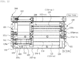
- an insect-proof window installation frame 500 is additionally provided, wherein the insect-proof window installation frame 500 comprises; an insect-proof screen mounting frame main body pocket 510 installed in a pocket shape; a rail 522 extending along the sliding movement direction of the sliding insect-proof window 500 at a position having a predetermined distance from the bottom surface or the ceiling of the insect-proof screen installation main body portion pocket 510; and a rail bridge 520 detachably inserted into the insect-proof screen installation main body portion pocket 510.
- a fastening groove 101a for the insect-proof window mounting frame may be provided on at least one outer surface of an outer surface of the outer vertical guide frame of the vertical guide frame 101 and a extended outer surface 102-out extended from an outer surface of the outer main body 120-out forming the main body 120 of the guide frame of the door guide frame 100, and it is preferable that a fastening protrusion 501 that can be engaged with the fastening groove 101a is protruded from the insect-proof screen installation main body portion pocket 510.
- an inner side of the insect-proof screen mounting frame main body part pocket 510 is preferably provided with a latching end 514 protruding and formed along a traveling direction of the rail 522.
- a latching end 514 protruding and formed along a traveling direction of the rail 522.
- an engagement protrusion 524 which is fitted to the latching end 514 is provided along the traveling direction of the rail 522.
- the rail bridge 520 is prevented from separating from the insect-proof screen installation main body portion pocket 510 unless a predetermined frictional force is generated and an external force is applied at a portion where the latching end 514 and the engagement protrusion 524 are engaged, it is preferable that the rail 522 is protruded from the upper surface of the rail bridge 520 and is easily detached and separated when the rail 522 is gripped and pulled.
- the rail bridge 520 may be formed of two or more rail bridge segments detachable from the inside of the insect-proof screen installation main body portion pocket 510.
- the pocket guide segments 130a and 130b supporting the sliding window 400 can be removed from the door guide frame 100, separation from the door guide frame 100 or installation on the door guide frame 100 may be performed, which process is substantially the same as the process outlined in Figures 1 to 4 of the accompanying drawings.
- the entire structure and operation of the present invention are described in Korean Patent Application No. 10-2012-0047789 (Korean Patent Registration No. 10-1367835 ) filed by the inventor of the present invention and PCT Application No. PCT/ KR2013/ 003912 published in a laid-open Publication No. WO 2013/ 168943A1 ), which is incorporated herein by reference in its entirety.
Landscapes
- Engineering & Computer Science (AREA)
- Structural Engineering (AREA)
- Civil Engineering (AREA)
- Mechanical Engineering (AREA)
- Life Sciences & Earth Sciences (AREA)
- Insects & Arthropods (AREA)
- Pest Control & Pesticides (AREA)
- Architecture (AREA)
- Wing Frames And Configurations (AREA)
- Special Wing (AREA)
- Support Devices For Sliding Doors (AREA)
Applications Claiming Priority (2)
| Application Number | Priority Date | Filing Date | Title |
|---|---|---|---|
| KR1020160142377A KR101953910B1 (ko) | 2016-10-28 | 2016-10-28 | 슬라이딩 창호용 분리 착탈 가능한 세그먼트 구조의 도어 가이드 프레임 |
| PCT/KR2017/012069 WO2018080256A2 (fr) | 2016-10-28 | 2017-10-30 | Châssis de guidage de porte de structure à segments démontables pour fenêtres et portes coulissantes |
Publications (3)
| Publication Number | Publication Date |
|---|---|
| EP3533957A2 true EP3533957A2 (fr) | 2019-09-04 |
| EP3533957A4 EP3533957A4 (fr) | 2020-07-01 |
| EP3533957B1 EP3533957B1 (fr) | 2021-10-20 |
Family
ID=62025174
Family Applications (1)
| Application Number | Title | Priority Date | Filing Date |
|---|---|---|---|
| EP17865977.7A Active EP3533957B1 (fr) | 2016-10-28 | 2017-10-30 | Structure à segments séparable et démontable pour fenêtres et portes coulissantes |
Country Status (5)
| Country | Link |
|---|---|
| US (1) | US11313171B2 (fr) |
| EP (1) | EP3533957B1 (fr) |
| JP (1) | JP7239180B2 (fr) |
| KR (1) | KR101953910B1 (fr) |
| WO (1) | WO2018080256A2 (fr) |
Families Citing this family (10)
| Publication number | Priority date | Publication date | Assignee | Title |
|---|---|---|---|---|
| PT109377A (pt) * | 2016-05-10 | 2017-11-10 | Bbg S A | Caixilharia invisível para portas e janelas de grandes áreas |
| GR1009233B (el) * | 2017-01-13 | 2018-02-22 | ORAMA MINIMAL FRAMES EΤΑΙΡΕΙΑ ΠΕΡΙΟΡΙΣΜΕΝΗΣ ΕΥΘΥΝΗΣ με δτ ORAMA MINIMAL FRAMES E.Π.Ε | Ημι-αορατος συνδυασμος θερμομονωτικων διατομων για ανεμποδιστη διελευση του κατω μερους συρομενου πορτοπαραθυρου |
| CH713489A1 (de) * | 2017-02-27 | 2018-08-31 | Guhl Beat | Bodenführung. |
| KR102000789B1 (ko) * | 2018-05-24 | 2019-07-16 | 주식회사 필로브 | 세그먼트 타입의 윈도우 프레임을 포함한 슬라이딩 창호 시스템을 구성하는 고정창의 유리 고정 가스켓과 창유리 패널 고정 브라켓의 설치 구조 |
| DE202018106791U1 (de) | 2018-11-29 | 2020-03-04 | Agtatec Ag | Automatisches Türsystem, insbesondere in Form einer Schiebetür oder einer Teleskopschiebetür oder einer Falttür und ein Gebäude mit einem solchen automatischen Türsystem |
| JP7418046B2 (ja) * | 2019-07-31 | 2024-01-19 | フィローブ カンパニー,リミテッド | スライディング窓戸の2辺支持フレームウィンドウサッシが相互に重なるセンターバー部分でのウィンドウフレームサッシの断熱及びガラスパネル支持構造 |
| JP7378856B2 (ja) * | 2019-08-20 | 2023-11-14 | フィローブ カンパニー,リミテッド | スライディング窓戸システムの2辺支持フレームウィンドウサッシとドアフレームとが相互に重なる側面セクションにおける断熱構造 |
| EP4033063B1 (fr) * | 2019-09-22 | 2024-05-01 | Filobe Co., Ltd. | Structure d'installation d'un joint d'étanchéité élastique fixé et installé en tant qu'élément d'étanchéité sur un support isolant de support de verre dans une fenêtre coulissante ayant un châssis de fenêtre de cadre de support à deux côtés |
| US11634940B2 (en) * | 2020-11-18 | 2023-04-25 | Goldbrecht Llc | Invisible sill—thermally broken |
| KR102619509B1 (ko) * | 2021-10-14 | 2023-12-28 | 김종훈 | 한옥의 단열 창호구조 |
Family Cites Families (23)
| Publication number | Priority date | Publication date | Assignee | Title |
|---|---|---|---|---|
| US3462884A (en) * | 1968-04-30 | 1969-08-26 | Alpana Aluminum Prod | Insulated metal frame and sliding closure |
| US4219971A (en) * | 1978-04-03 | 1980-09-02 | Curtis Mauroner | Pocket window |
| US4599836A (en) * | 1985-06-20 | 1986-07-15 | Randy Melcher | Self-storing window assembly |
| ATE90768T1 (de) * | 1989-03-02 | 1993-07-15 | Gerhard Mische | Rahmen mit fest- und/oder schiebeelementen. |
| US5884361A (en) * | 1994-10-06 | 1999-03-23 | Anthony's Manufacturing Company | Slider door mechanism, running gear mechanism and closure return |
| DE10081553D2 (de) | 1999-05-26 | 2001-10-04 | Lamberts Glasfabrik | Halteschiene zum Halten von Glasprofilelementen |
| JP2001032637A (ja) * | 1999-07-22 | 2001-02-06 | Sankyo Alum Ind Co Ltd | 断熱形材 |
| JP2001173314A (ja) | 1999-12-21 | 2001-06-26 | Fujisash Co | 断熱アルミサッシ構成材 |
| CA2524299A1 (fr) * | 2004-10-22 | 2006-04-22 | Alpa Lumber Inc. | Profile extrude |
| US7555871B1 (en) * | 2005-02-03 | 2009-07-07 | Guardian, Llc | Window framing system for sliding windows |
| KR100768933B1 (ko) * | 2005-09-08 | 2007-10-22 | 천태호 | 조립식 창호 장치 |
| NZ583546A (en) * | 2007-08-29 | 2012-12-21 | Aneeta Window Systems Vic Pty Ltd | Sliding window or door with multiple panes and a sill and a head formed of parts snap-fitted together |
| KR100914756B1 (ko) * | 2009-03-02 | 2009-08-31 | 김순석 | 시공이 용이한 창호장치 |
| US20120109569A1 (en) | 2010-10-27 | 2012-05-03 | General Electric Company | Diagnosis of bearing thermal anomalies in an electrical machine |
| KR101055326B1 (ko) * | 2011-03-17 | 2011-08-08 | 김순석 | 레일 은폐형 창호장치 |
| KR101094066B1 (ko) * | 2011-07-25 | 2011-12-15 | 김순석 | 자동문 및 반자동문용 창호 장치 |
| KR101367835B1 (ko) * | 2012-05-06 | 2014-03-03 | 이광석 | 분리 착탈 가능한 세그먼트 구조의 도어 가이드 프레임을 포함한 슬라이딩 창호 설치 구조 |
| KR101914795B1 (ko) | 2013-05-10 | 2018-11-02 | (주)엘지하우시스 | 착탈식 단열보강부재를 구비한 창호 |
| KR101441504B1 (ko) | 2013-09-17 | 2014-09-17 | 주식회사 필로브 | 분리 착탈 가능한 세그먼트 구조의 레일 프레임을 포함한 슬라이딩 방충창 설치 구조 |
| KR101446899B1 (ko) * | 2014-02-25 | 2014-10-06 | 김순석 | ㄷ자 형상의 롤러지지대를 구비한 평레일 창호장치 |
| CN203846942U (zh) | 2014-04-23 | 2014-09-24 | 张承斌 | 一种强密封推拉窗 |
| KR101507484B1 (ko) * | 2014-07-16 | 2015-04-07 | 주식회사 밝은창 | 분리가 용이한 고 기밀성 단열 창호 및 이의 제조방법 |
| WO2018053131A1 (fr) * | 2016-09-15 | 2018-03-22 | Goldbrecht Inc. | Ensemble galet pour porte et fenêtre coulissante |
-
2016
- 2016-10-28 KR KR1020160142377A patent/KR101953910B1/ko active Active
-
2017
- 2017-10-28 US US16/345,827 patent/US11313171B2/en active Active
- 2017-10-30 JP JP2019522875A patent/JP7239180B2/ja active Active
- 2017-10-30 EP EP17865977.7A patent/EP3533957B1/fr active Active
- 2017-10-30 WO PCT/KR2017/012069 patent/WO2018080256A2/fr not_active Ceased
Also Published As
| Publication number | Publication date |
|---|---|
| JP7239180B2 (ja) | 2023-03-14 |
| EP3533957B1 (fr) | 2021-10-20 |
| US20200056419A1 (en) | 2020-02-20 |
| WO2018080256A3 (fr) | 2018-06-21 |
| WO2018080256A2 (fr) | 2018-05-03 |
| US11313171B2 (en) | 2022-04-26 |
| JP2019536925A (ja) | 2019-12-19 |
| EP3533957A4 (fr) | 2020-07-01 |
| KR101953910B1 (ko) | 2019-03-05 |
| KR20180046781A (ko) | 2018-05-09 |
Similar Documents
| Publication | Publication Date | Title |
|---|---|---|
| EP3533957B1 (fr) | Structure à segments séparable et démontable pour fenêtres et portes coulissantes | |
| US9512656B2 (en) | Sliding window installation structure including door guide frame having separable segment structure | |
| EP2777458A1 (fr) | Embase amovible pour ensemble de rail de porte de douche | |
| US8936318B2 (en) | Vehicle seat | |
| KR102062223B1 (ko) | 미닫이 여닫이 겸용 연동도어 및 이를 위한 연결구 | |
| US9433325B2 (en) | Sliding shower door guide and drain assembly | |
| JP2009102863A (ja) | 引戸の施工方法、及び引戸ユニット | |
| JP2014210531A (ja) | ウェザストリップ構造 | |
| JP5883643B2 (ja) | 引戸連動設備および受け部材 | |
| JP6134528B2 (ja) | 建物用遮蔽体及びパネル構造体、並びに建物用遮蔽体の設置方法 | |
| JP2017110389A (ja) | 建具 | |
| JP7473452B2 (ja) | 建具 | |
| KR200457715Y1 (ko) | 조명기구의 설치구조 | |
| AU2019232780B2 (en) | An Adjustable Cavity Slider Guiding Assembly, Cavity Slider and Method of Installation | |
| KR102735872B1 (ko) | 미닫이 여닫이 겸용 연동도어의 도어 연결 장치 | |
| CN215803974U (zh) | 淋浴房的滑轮限位结构及具有该滑轮限位结构的淋浴房 | |
| JP7166981B2 (ja) | 建具 | |
| JP2021031906A (ja) | 建具 | |
| JP2008159904A (ja) | 電気電子機器収納箱 | |
| JP2018159230A (ja) | パネル体の天井への固定構造 | |
| JP2008208683A (ja) | 引き戸の案内構造 | |
| JP2004108025A (ja) | シャッター | |
| JP2003343148A (ja) | スライドレール式上吊り引戸の吊設構造 | |
| EP1902499A1 (fr) | Pièce de coin pour système de jonction de câbles | |
| JP6193756B2 (ja) | 日射遮蔽装置 |
Legal Events
| Date | Code | Title | Description |
|---|---|---|---|
| STAA | Information on the status of an ep patent application or granted ep patent |
Free format text: STATUS: THE INTERNATIONAL PUBLICATION HAS BEEN MADE |
|
| PUAI | Public reference made under article 153(3) epc to a published international application that has entered the european phase |
Free format text: ORIGINAL CODE: 0009012 |
|
| STAA | Information on the status of an ep patent application or granted ep patent |
Free format text: STATUS: REQUEST FOR EXAMINATION WAS MADE |
|
| 17P | Request for examination filed |
Effective date: 20190528 |
|
| AK | Designated contracting states |
Kind code of ref document: A2 Designated state(s): AL AT BE BG CH CY CZ DE DK EE ES FI FR GB GR HR HU IE IS IT LI LT LU LV MC MK MT NL NO PL PT RO RS SE SI SK SM TR |
|
| AX | Request for extension of the european patent |
Extension state: BA ME |
|
| DAV | Request for validation of the european patent (deleted) | ||
| DAX | Request for extension of the european patent (deleted) | ||
| A4 | Supplementary search report drawn up and despatched |
Effective date: 20200529 |
|
| RIC1 | Information provided on ipc code assigned before grant |
Ipc: E06B 3/46 20060101ALI20200525BHEP Ipc: E06B 3/263 20060101ALI20200525BHEP Ipc: E05D 15/06 20060101AFI20200525BHEP |
|
| GRAP | Despatch of communication of intention to grant a patent |
Free format text: ORIGINAL CODE: EPIDOSNIGR1 |
|
| STAA | Information on the status of an ep patent application or granted ep patent |
Free format text: STATUS: GRANT OF PATENT IS INTENDED |
|
| INTG | Intention to grant announced |
Effective date: 20210519 |
|
| GRAS | Grant fee paid |
Free format text: ORIGINAL CODE: EPIDOSNIGR3 |
|
| GRAA | (expected) grant |
Free format text: ORIGINAL CODE: 0009210 |
|
| STAA | Information on the status of an ep patent application or granted ep patent |
Free format text: STATUS: THE PATENT HAS BEEN GRANTED |
|
| AK | Designated contracting states |
Kind code of ref document: B1 Designated state(s): AL AT BE BG CH CY CZ DE DK EE ES FI FR GB GR HR HU IE IS IT LI LT LU LV MC MK MT NL NO PL PT RO RS SE SI SK SM TR |
|
| REG | Reference to a national code |
Ref country code: GB Ref legal event code: FG4D |
|
| REG | Reference to a national code |
Ref country code: CH Ref legal event code: EP |
|
| REG | Reference to a national code |
Ref country code: IE Ref legal event code: FG4D |
|
| REG | Reference to a national code |
Ref country code: DE Ref legal event code: R096 Ref document number: 602017048058 Country of ref document: DE |
|
| REG | Reference to a national code |
Ref country code: AT Ref legal event code: REF Ref document number: 1440102 Country of ref document: AT Kind code of ref document: T Effective date: 20211115 |
|
| REG | Reference to a national code |
Ref country code: LT Ref legal event code: MG9D |
|
| REG | Reference to a national code |
Ref country code: NL Ref legal event code: MP Effective date: 20211020 |
|
| REG | Reference to a national code |
Ref country code: AT Ref legal event code: MK05 Ref document number: 1440102 Country of ref document: AT Kind code of ref document: T Effective date: 20211020 |
|
| PG25 | Lapsed in a contracting state [announced via postgrant information from national office to epo] |
Ref country code: RS Free format text: LAPSE BECAUSE OF FAILURE TO SUBMIT A TRANSLATION OF THE DESCRIPTION OR TO PAY THE FEE WITHIN THE PRESCRIBED TIME-LIMIT Effective date: 20211020 Ref country code: LT Free format text: LAPSE BECAUSE OF FAILURE TO SUBMIT A TRANSLATION OF THE DESCRIPTION OR TO PAY THE FEE WITHIN THE PRESCRIBED TIME-LIMIT Effective date: 20211020 Ref country code: FI Free format text: LAPSE BECAUSE OF FAILURE TO SUBMIT A TRANSLATION OF THE DESCRIPTION OR TO PAY THE FEE WITHIN THE PRESCRIBED TIME-LIMIT Effective date: 20211020 Ref country code: BG Free format text: LAPSE BECAUSE OF FAILURE TO SUBMIT A TRANSLATION OF THE DESCRIPTION OR TO PAY THE FEE WITHIN THE PRESCRIBED TIME-LIMIT Effective date: 20220120 Ref country code: AT Free format text: LAPSE BECAUSE OF FAILURE TO SUBMIT A TRANSLATION OF THE DESCRIPTION OR TO PAY THE FEE WITHIN THE PRESCRIBED TIME-LIMIT Effective date: 20211020 |
|
| PG25 | Lapsed in a contracting state [announced via postgrant information from national office to epo] |
Ref country code: IS Free format text: LAPSE BECAUSE OF FAILURE TO SUBMIT A TRANSLATION OF THE DESCRIPTION OR TO PAY THE FEE WITHIN THE PRESCRIBED TIME-LIMIT Effective date: 20220220 Ref country code: SE Free format text: LAPSE BECAUSE OF FAILURE TO SUBMIT A TRANSLATION OF THE DESCRIPTION OR TO PAY THE FEE WITHIN THE PRESCRIBED TIME-LIMIT Effective date: 20211020 Ref country code: PT Free format text: LAPSE BECAUSE OF FAILURE TO SUBMIT A TRANSLATION OF THE DESCRIPTION OR TO PAY THE FEE WITHIN THE PRESCRIBED TIME-LIMIT Effective date: 20220221 Ref country code: PL Free format text: LAPSE BECAUSE OF FAILURE TO SUBMIT A TRANSLATION OF THE DESCRIPTION OR TO PAY THE FEE WITHIN THE PRESCRIBED TIME-LIMIT Effective date: 20211020 Ref country code: NO Free format text: LAPSE BECAUSE OF FAILURE TO SUBMIT A TRANSLATION OF THE DESCRIPTION OR TO PAY THE FEE WITHIN THE PRESCRIBED TIME-LIMIT Effective date: 20220120 Ref country code: NL Free format text: LAPSE BECAUSE OF FAILURE TO SUBMIT A TRANSLATION OF THE DESCRIPTION OR TO PAY THE FEE WITHIN THE PRESCRIBED TIME-LIMIT Effective date: 20211020 Ref country code: LV Free format text: LAPSE BECAUSE OF FAILURE TO SUBMIT A TRANSLATION OF THE DESCRIPTION OR TO PAY THE FEE WITHIN THE PRESCRIBED TIME-LIMIT Effective date: 20211020 Ref country code: HR Free format text: LAPSE BECAUSE OF FAILURE TO SUBMIT A TRANSLATION OF THE DESCRIPTION OR TO PAY THE FEE WITHIN THE PRESCRIBED TIME-LIMIT Effective date: 20211020 Ref country code: GR Free format text: LAPSE BECAUSE OF FAILURE TO SUBMIT A TRANSLATION OF THE DESCRIPTION OR TO PAY THE FEE WITHIN THE PRESCRIBED TIME-LIMIT Effective date: 20220121 Ref country code: ES Free format text: LAPSE BECAUSE OF FAILURE TO SUBMIT A TRANSLATION OF THE DESCRIPTION OR TO PAY THE FEE WITHIN THE PRESCRIBED TIME-LIMIT Effective date: 20211020 |
|
| REG | Reference to a national code |
Ref country code: BE Ref legal event code: MM Effective date: 20211031 |
|
| REG | Reference to a national code |
Ref country code: DE Ref legal event code: R097 Ref document number: 602017048058 Country of ref document: DE |
|
| PG25 | Lapsed in a contracting state [announced via postgrant information from national office to epo] |
Ref country code: SM Free format text: LAPSE BECAUSE OF FAILURE TO SUBMIT A TRANSLATION OF THE DESCRIPTION OR TO PAY THE FEE WITHIN THE PRESCRIBED TIME-LIMIT Effective date: 20211020 Ref country code: SK Free format text: LAPSE BECAUSE OF FAILURE TO SUBMIT A TRANSLATION OF THE DESCRIPTION OR TO PAY THE FEE WITHIN THE PRESCRIBED TIME-LIMIT Effective date: 20211020 Ref country code: RO Free format text: LAPSE BECAUSE OF FAILURE TO SUBMIT A TRANSLATION OF THE DESCRIPTION OR TO PAY THE FEE WITHIN THE PRESCRIBED TIME-LIMIT Effective date: 20211020 Ref country code: MC Free format text: LAPSE BECAUSE OF FAILURE TO SUBMIT A TRANSLATION OF THE DESCRIPTION OR TO PAY THE FEE WITHIN THE PRESCRIBED TIME-LIMIT Effective date: 20211020 Ref country code: LU Free format text: LAPSE BECAUSE OF NON-PAYMENT OF DUE FEES Effective date: 20211030 Ref country code: EE Free format text: LAPSE BECAUSE OF FAILURE TO SUBMIT A TRANSLATION OF THE DESCRIPTION OR TO PAY THE FEE WITHIN THE PRESCRIBED TIME-LIMIT Effective date: 20211020 Ref country code: DK Free format text: LAPSE BECAUSE OF FAILURE TO SUBMIT A TRANSLATION OF THE DESCRIPTION OR TO PAY THE FEE WITHIN THE PRESCRIBED TIME-LIMIT Effective date: 20211020 Ref country code: CZ Free format text: LAPSE BECAUSE OF FAILURE TO SUBMIT A TRANSLATION OF THE DESCRIPTION OR TO PAY THE FEE WITHIN THE PRESCRIBED TIME-LIMIT Effective date: 20211020 Ref country code: BE Free format text: LAPSE BECAUSE OF NON-PAYMENT OF DUE FEES Effective date: 20211031 |
|
| PLBE | No opposition filed within time limit |
Free format text: ORIGINAL CODE: 0009261 |
|
| STAA | Information on the status of an ep patent application or granted ep patent |
Free format text: STATUS: NO OPPOSITION FILED WITHIN TIME LIMIT |
|
| 26N | No opposition filed |
Effective date: 20220721 |
|
| GBPC | Gb: european patent ceased through non-payment of renewal fee |
Effective date: 20220120 |
|
| PG25 | Lapsed in a contracting state [announced via postgrant information from national office to epo] |
Ref country code: IE Free format text: LAPSE BECAUSE OF NON-PAYMENT OF DUE FEES Effective date: 20211030 Ref country code: GB Free format text: LAPSE BECAUSE OF NON-PAYMENT OF DUE FEES Effective date: 20220120 Ref country code: AL Free format text: LAPSE BECAUSE OF FAILURE TO SUBMIT A TRANSLATION OF THE DESCRIPTION OR TO PAY THE FEE WITHIN THE PRESCRIBED TIME-LIMIT Effective date: 20211020 |
|
| PG25 | Lapsed in a contracting state [announced via postgrant information from national office to epo] |
Ref country code: SI Free format text: LAPSE BECAUSE OF FAILURE TO SUBMIT A TRANSLATION OF THE DESCRIPTION OR TO PAY THE FEE WITHIN THE PRESCRIBED TIME-LIMIT Effective date: 20211020 Ref country code: FR Free format text: LAPSE BECAUSE OF NON-PAYMENT OF DUE FEES Effective date: 20211220 |
|
| PG25 | Lapsed in a contracting state [announced via postgrant information from national office to epo] |
Ref country code: IT Free format text: LAPSE BECAUSE OF FAILURE TO SUBMIT A TRANSLATION OF THE DESCRIPTION OR TO PAY THE FEE WITHIN THE PRESCRIBED TIME-LIMIT Effective date: 20211020 |
|
| PG25 | Lapsed in a contracting state [announced via postgrant information from national office to epo] |
Ref country code: CY Free format text: LAPSE BECAUSE OF FAILURE TO SUBMIT A TRANSLATION OF THE DESCRIPTION OR TO PAY THE FEE WITHIN THE PRESCRIBED TIME-LIMIT Effective date: 20211020 |
|
| PG25 | Lapsed in a contracting state [announced via postgrant information from national office to epo] |
Ref country code: HU Free format text: LAPSE BECAUSE OF FAILURE TO SUBMIT A TRANSLATION OF THE DESCRIPTION OR TO PAY THE FEE WITHIN THE PRESCRIBED TIME-LIMIT; INVALID AB INITIO Effective date: 20171030 |
|
| PG25 | Lapsed in a contracting state [announced via postgrant information from national office to epo] |
Ref country code: MK Free format text: LAPSE BECAUSE OF FAILURE TO SUBMIT A TRANSLATION OF THE DESCRIPTION OR TO PAY THE FEE WITHIN THE PRESCRIBED TIME-LIMIT Effective date: 20211020 |
|
| PG25 | Lapsed in a contracting state [announced via postgrant information from national office to epo] |
Ref country code: MT Free format text: LAPSE BECAUSE OF FAILURE TO SUBMIT A TRANSLATION OF THE DESCRIPTION OR TO PAY THE FEE WITHIN THE PRESCRIBED TIME-LIMIT Effective date: 20211020 |
|
| REG | Reference to a national code |
Ref country code: CH Ref legal event code: U11 Free format text: ST27 STATUS EVENT CODE: U-0-0-U10-U11 (AS PROVIDED BY THE NATIONAL OFFICE) Effective date: 20251120 |
|
| PG25 | Lapsed in a contracting state [announced via postgrant information from national office to epo] |
Ref country code: TR Free format text: LAPSE BECAUSE OF FAILURE TO SUBMIT A TRANSLATION OF THE DESCRIPTION OR TO PAY THE FEE WITHIN THE PRESCRIBED TIME-LIMIT Effective date: 20211020 |
|
| PGFP | Annual fee paid to national office [announced via postgrant information from national office to epo] |
Ref country code: DE Payment date: 20251023 Year of fee payment: 9 |
|
| PGFP | Annual fee paid to national office [announced via postgrant information from national office to epo] |
Ref country code: CH Payment date: 20251120 Year of fee payment: 9 |