EP3534009A1 - Verdichter, klimaanlage und fahrzeug - Google Patents
Verdichter, klimaanlage und fahrzeug Download PDFInfo
- Publication number
- EP3534009A1 EP3534009A1 EP17863739.3A EP17863739A EP3534009A1 EP 3534009 A1 EP3534009 A1 EP 3534009A1 EP 17863739 A EP17863739 A EP 17863739A EP 3534009 A1 EP3534009 A1 EP 3534009A1
- Authority
- EP
- European Patent Office
- Prior art keywords
- cavity
- flash
- compressor
- flash cavity
- compression
- Prior art date
- Legal status (The legal status is an assumption and is not a legal conclusion. Google has not performed a legal analysis and makes no representation as to the accuracy of the status listed.)
- Granted
Links
Images







Classifications
-
- B—PERFORMING OPERATIONS; TRANSPORTING
- B60—VEHICLES IN GENERAL
- B60H—ARRANGEMENTS OF HEATING, COOLING, VENTILATING OR OTHER AIR-TREATING DEVICES SPECIALLY ADAPTED FOR PASSENGER OR GOODS SPACES OF VEHICLES
- B60H1/00—Heating, cooling or ventilating devices
- B60H1/32—Cooling devices
- B60H1/3204—Cooling devices using compression
- B60H1/3223—Cooling devices using compression characterised by the arrangement or type of the compressor
-
- F—MECHANICAL ENGINEERING; LIGHTING; HEATING; WEAPONS; BLASTING
- F04—POSITIVE - DISPLACEMENT MACHINES FOR LIQUIDS; PUMPS FOR LIQUIDS OR ELASTIC FLUIDS
- F04C—ROTARY-PISTON, OR OSCILLATING-PISTON, POSITIVE-DISPLACEMENT MACHINES FOR LIQUIDS; ROTARY-PISTON, OR OSCILLATING-PISTON, POSITIVE-DISPLACEMENT PUMPS
- F04C18/00—Rotary-piston pumps specially adapted for elastic fluids
- F04C18/02—Rotary-piston pumps specially adapted for elastic fluids of arcuate-engagement type, i.e. with circular translatory movement of co-operating members, each member having the same number of teeth or tooth-equivalents
- F04C18/0207—Rotary-piston pumps specially adapted for elastic fluids of arcuate-engagement type, i.e. with circular translatory movement of co-operating members, each member having the same number of teeth or tooth-equivalents both members having co-operating elements in spiral form
- F04C18/0215—Rotary-piston pumps specially adapted for elastic fluids of arcuate-engagement type, i.e. with circular translatory movement of co-operating members, each member having the same number of teeth or tooth-equivalents both members having co-operating elements in spiral form where only one member is moving
-
- B—PERFORMING OPERATIONS; TRANSPORTING
- B60—VEHICLES IN GENERAL
- B60H—ARRANGEMENTS OF HEATING, COOLING, VENTILATING OR OTHER AIR-TREATING DEVICES SPECIALLY ADAPTED FOR PASSENGER OR GOODS SPACES OF VEHICLES
- B60H1/00—Heating, cooling or ventilating devices
-
- B—PERFORMING OPERATIONS; TRANSPORTING
- B60—VEHICLES IN GENERAL
- B60H—ARRANGEMENTS OF HEATING, COOLING, VENTILATING OR OTHER AIR-TREATING DEVICES SPECIALLY ADAPTED FOR PASSENGER OR GOODS SPACES OF VEHICLES
- B60H1/00—Heating, cooling or ventilating devices
- B60H1/00357—Air-conditioning arrangements specially adapted for particular vehicles
- B60H1/00385—Air-conditioning arrangements specially adapted for particular vehicles for vehicles having an electrical drive, e.g. hybrid or fuel cell
- B60H1/00392—Air-conditioning arrangements specially adapted for particular vehicles for vehicles having an electrical drive, e.g. hybrid or fuel cell for electric vehicles having only electric drive means
-
- F—MECHANICAL ENGINEERING; LIGHTING; HEATING; WEAPONS; BLASTING
- F04—POSITIVE - DISPLACEMENT MACHINES FOR LIQUIDS; PUMPS FOR LIQUIDS OR ELASTIC FLUIDS
- F04C—ROTARY-PISTON, OR OSCILLATING-PISTON, POSITIVE-DISPLACEMENT MACHINES FOR LIQUIDS; ROTARY-PISTON, OR OSCILLATING-PISTON, POSITIVE-DISPLACEMENT PUMPS
- F04C15/00—Component parts, details or accessories of machines, pumps or pumping installations, not provided for in groups F04C2/00 - F04C14/00
- F04C15/0096—Heating; Cooling
-
- F—MECHANICAL ENGINEERING; LIGHTING; HEATING; WEAPONS; BLASTING
- F04—POSITIVE - DISPLACEMENT MACHINES FOR LIQUIDS; PUMPS FOR LIQUIDS OR ELASTIC FLUIDS
- F04C—ROTARY-PISTON, OR OSCILLATING-PISTON, POSITIVE-DISPLACEMENT MACHINES FOR LIQUIDS; ROTARY-PISTON, OR OSCILLATING-PISTON, POSITIVE-DISPLACEMENT PUMPS
- F04C18/00—Rotary-piston pumps specially adapted for elastic fluids
- F04C18/02—Rotary-piston pumps specially adapted for elastic fluids of arcuate-engagement type, i.e. with circular translatory movement of co-operating members, each member having the same number of teeth or tooth-equivalents
-
- F—MECHANICAL ENGINEERING; LIGHTING; HEATING; WEAPONS; BLASTING
- F04—POSITIVE - DISPLACEMENT MACHINES FOR LIQUIDS; PUMPS FOR LIQUIDS OR ELASTIC FLUIDS
- F04C—ROTARY-PISTON, OR OSCILLATING-PISTON, POSITIVE-DISPLACEMENT MACHINES FOR LIQUIDS; ROTARY-PISTON, OR OSCILLATING-PISTON, POSITIVE-DISPLACEMENT PUMPS
- F04C19/00—Rotary-piston pumps with fluid ring or the like, specially adapted for elastic fluids
- F04C19/004—Details concerning the operating liquid, e.g. nature, separation, cooling, cleaning, control of the supply
-
- F—MECHANICAL ENGINEERING; LIGHTING; HEATING; WEAPONS; BLASTING
- F04—POSITIVE - DISPLACEMENT MACHINES FOR LIQUIDS; PUMPS FOR LIQUIDS OR ELASTIC FLUIDS
- F04C—ROTARY-PISTON, OR OSCILLATING-PISTON, POSITIVE-DISPLACEMENT MACHINES FOR LIQUIDS; ROTARY-PISTON, OR OSCILLATING-PISTON, POSITIVE-DISPLACEMENT PUMPS
- F04C29/00—Component parts, details or accessories of pumps or pumping installations, not provided for in groups F04C18/00 - F04C28/00
-
- F—MECHANICAL ENGINEERING; LIGHTING; HEATING; WEAPONS; BLASTING
- F04—POSITIVE - DISPLACEMENT MACHINES FOR LIQUIDS; PUMPS FOR LIQUIDS OR ELASTIC FLUIDS
- F04C—ROTARY-PISTON, OR OSCILLATING-PISTON, POSITIVE-DISPLACEMENT MACHINES FOR LIQUIDS; ROTARY-PISTON, OR OSCILLATING-PISTON, POSITIVE-DISPLACEMENT PUMPS
- F04C29/00—Component parts, details or accessories of pumps or pumping installations, not provided for in groups F04C18/00 - F04C28/00
- F04C29/0007—Injection of a fluid in the working chamber for sealing, cooling and lubricating
Definitions
- the present disclosure relates to the technical field of air conditioners, in particular to a compressor, an air conditioning system and a vehicle.
- the vehicle-mounted air conditioning system therein should achieve rapid cooling and heating and maintain low power consumption. Therefore, the air conditioning system of the electric vehicle requires higher energy efficiency and higher refrigerating and heating capacity of a compressor. Especially in cold winter, when the external ambient temperature is less than -10°C, the output efficiency of the battery is low. In this case, the vehicle-mounted air conditioner needs to achieve rapid heating and maintain high energy efficiency at such a harsh ambient temperature, which imposes higher requirements on the energy efficiency and application environment of the vehicle-mounted compressor.
- the conventional compressor hardly meets the requirement for ultra-low temperature rapid heating, so an enthalpy increasing technology is needed.
- scroll compressors with the characteristics of energy conservation, low noise and high reliability have been widely used as the latest-generation vehicle-mounted compressors.
- the conventional scroll compressors hardly meet the requirement for ultra-low temperature rapid heating.
- the enthalpy increasing technology is used in the industry to solve the problem of ultra-low temperature rapid heating of the scroll compressors.
- the air conditioning system with an enthalpy increasing system is more complex.
- the air conditioning system with an enthalpy increasing system and a scroll compressor requires an additional intermediate cooling structure, i.e., a flash device, with more pipeline and space requirements, where its structure is shown in FIG. 1 .
- a flash device i.e., a flash device
- Excessive pipeline arrangements in the air conditioning system challenge the endurance of the electric vehicle and the reliability of the system itself.
- the enthalpy increasing air conditioning systems are mature and have been widely used in household and commercial air conditioning systems, but are still rarely used in the existing vehicle-mounted air conditioning systems.
- the main reason is that the existing enthalpy increasing systems themselves are more complicated, and the vehicle-mounted systems need to be as light as possible.
- non-electric vehicles can be heated using the heat of vehicle engines, which alleviates the need for the heating capacity of the air conditioning systems, while electric vehicles cannot use the heat of engines and are completely supplied with heat by the air conditioning systems. Therefore, an enthalpy increasing system with intermediate cooling and gas supplying functions for the compressor is urgently required for the electric vehicle.
- the present disclosure provides a compressor, an air conditioning system, and a vehicle, wherein the integrated design of a compressor and a flash device simplifies the air conditioning system and improves the reliability of the system.
- a first aspect of the present disclosure provides a compressor comprising:
- the flash cavity is adjacent to the compression cavity, and the flash cavity and the compression cavity are separated by a common side wall.
- the communicating passage is arranged on the common side wall.
- a through hole being the communicating passage is provided on the common side wall to directly communicate the flash cavity and the compression cavity.
- the outer wall of the body of the compressor forms a part of the wall of the flash cavity.
- the compressor has an aluminum alloy body.
- the compressor is an electric compressor, and the flash cavity and a drive motor of the compressor are arranged on two sides of the compression cavity respectively.
- the compressor is a scroll compressor having a body, and the body is provided with an inflow port, the compression cavity, a discharge port and the flash cavity; the inflow port, the discharge port and the flash cavity communicate with the compression cavity; wherein the compression cavity is configured to compress a first fluid entering via the inflow port; and the flash cavity is configured produce a second fluid by flashing and deliver the second fluid to the compression cavity for compression.
- the body comprises a static scroll plate, a dynamic scroll plate and a shell
- the static scroll plate is provided with a first end plate and a first spiral scroll extending outward from the first end plate
- the dynamic scroll plate is provided with a second end plate and a second spiral scroll extending outward from the second end plate
- the first spiral scroll and the second spiral scroll are matched, and when the dynamic scroll plate rotates relative to the static scroll plate, a plurality of mobile cavities being the compression cavity are defined between the first spiral scroll and the second spiral scroll
- the static scroll plate and the dynamic scroll plate are arranged inside the shell, and the flash cavity is arranged on at least one of the shell and the static scroll plate.
- the shell comprises a first cover and a second cover that are detachably connected, the first cover is located on a side of the static scroll plate where the first spiral scroll is not arranged, and the flash cavity is arranged on the first cover.
- the shell comprises a first cover, a second cover and a sealing cover plate that are detachably connected, the first cover is located on a side of the static scroll plate where the first spiral scroll is not arranged, and the sealing cover plate is arranged on a side of the first cover away from the second cover; a part of the flash cavity is arranged on the first cover, and the other part of the flash cavity is arranged on the sealing cover plate; or, the flash cavity is arranged on the first cover and has an opening, and the sealing cover plate closes the opening of the flash cavity.
- a gas-liquid separation structure inclined with respect to the flow direction of the second fluid is arranged in the flash cavity to separate the liquid entrained in the second fluid.
- the gas-liquid separation structure comprises baffle, and the extending direction of the baffle is at an obtuse or right angle to the flow direction of the second fluid.
- the gas-liquid separation structure comprises at least two baffles, and the two baffles are arranged in a splayed shape.
- the gas-liquid separation structure comprises two groups of baffles staggered to form a split-flow passage.
- the communicating passage is arranged in the first end plate of the static scroll plate, and the flash cavity is communicated with the compression cavity by the communicating passage.
- the communicating passage comprises an axial passage and a radial passage that communicate with each other, one end of the axial passage away from the radial passage communicates with the flash cavity, and one end of the radial passage away from the axial passage communicates with the compression cavity.
- the communicating passage extends in the axial direction of the scroll compressor.
- the compression cavity is provided with an axial through hole communicating with the flash cavity to form the enthalpy increasing gas supply port.
- a first opening of the flash cavity being the flash cavity inlet is arranged at the top end of the flash cavity to introduce a fluid to be flashed
- a second opening of the flash cavity being the flash cavity liquid outlet is arranged at the bottom end of the flash cavity for discharge the liquid that is not flashed
- a third opening of the flash cavity being the flash cavity gas outlet is arranged at the top end of the flash cavity to discharge the flashed second fluid; and the third opening of the flash cavity communicates with the compression cavity.
- a second aspect of the present disclosure provides an air conditioning system, comprising a compressor according to any item of the first aspect of the present disclosure, a condenser and an evaporator, the flash cavity inlet communicating to the outlet of the condenser, and the flash cavity liquid outlet communicating to the inlet of the evaporator.
- the air conditioning system further comprises a fluid supply component in communication with the flash cavity, and the flash cavity is configured to flash a fluid supplied by the fluid supply component to produce a second fluid.
- a third aspect of the present disclosure provides a vehicle, comprising an air conditioning system according to any item of the second aspect of the present disclosure.
- the vehicle is a new energy vehicle.
- the vehicle is an electric vehicle.
- the compressor, the air conditioning system and the vehicle provided by the present disclosure have the advantages that the flasher structure is arranged on the compressor body, so that the air conditioning system is simpler and more compact; the gas supply enthalpy increasing pipelines between the flasher and the compressor are reduced, the intermediate cooled gas flashed can quickly enter the compression cavity, and the pressure loss in the intermediate pipeline and the temperature rise in the pipelines are reduced; and the integrated design of the flasher structure and the compressor increases the vibration resistance of the flash structure, so that the flash structure is more suitable for the vehicle-mounted air conditioning system, and the reliability of the enthalpy increasing system is improved.
- the integrated scroll compressor provided by the above technical solution integrates the functions of compression, flashing and enthalpy increase by gas replenishment, and has the advantages of simple flash structure, fast gas supply and the like.
- Reference signs in the prior art of FIG. 1 represent: 01, compressor; 02, condenser; 03, evaporator; 04, system pipeline; 05, flasher; Ps, suction side refrigerant; Pd, exhaust side refrigerant; a, flasher gas outlet; b, enthalpy increasing gas supply port; Pm, flash intermediate pressure.
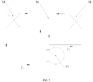
- FIG. 2 and FIG. 3 represent: 11, compressor; 12, condenser; 13, evaporator; 14, system pipeline; 16, drive motor; 17, compression cavity; 18, flash cavity; 19, communicating passage; PI, condenser outlet high-pressure refrigerant; P2, flash cavity cooled refrigerant.
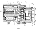
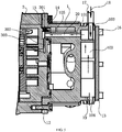
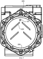
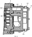
- FIG. 4 to FIG. 17 represent: 1, first cover; 2, second cover; 3, static scroll plate; 4, dynamic scroll plate; 5, upper bracket; 6, drive motor; 7, drive controller; 8, auxiliary bearing; 9, crankshaft 10, main bearing; 11, tail bearing; 12, fixing assembly bolt; 13, sealing cover plate; 14, O ring; 15, sealing thread plug; 16, fixing bolt; 17, condenser access pipe; 18, refrigerant liquid (condenser effluent); 19, refrigerant liquid (flash cavity effluent); 20, refrigerant gas flowing into the compression cavity; 21, scroll compressor; 22, condenser; 23, evaporator; 31, first end plate; 32, first spiral scroll; 33, communicating passage; 41, second end plate; 42, second spiral scroll; 100, inflow port; 101, third opening; 102, gas-liquid separation structure; 103, first opening; 104, second opening; 105, extending passage; 200, compression cavity; 211, gas-liquid mixed refrigerant; 222, liquid refrigerant; 300, flash cavity; 301, axial passage;
- the present disclosure proposes an enthalpy increasing air conditioning system that is more suitable for an electric vehicle, where the integrated design of a vehicle-mounted electric compressor and an intermediate cooling flash device simplifies the vehicle-mounted enthalpy increasing air conditioning system and improves the reliability of the system.
- the air conditioning system provided by the embodiment shown in FIG. 2 and FIG. 3 includes a compressor 11, a condenser 12 and an evaporator 13; the compressor 11 includes a compression cavity 17 for compressing a refrigerant, and the core improvement lies in that:
- Low-pressure refrigerant gas evaporated from the evaporator 13 is continuously sucked into the compressor 11 for compression.
- the low-pressure refrigerant gas Ps is compressed into high-temperature and high-pressure refrigerant gas Pd and discharged from the compressor 11 into the condenser 12.
- the high-temperature and high-pressure refrigerant gas is isobarically cooled in the condenser 12 and then enters the flash cavity 18 of the compressor 11.
- the liquid refrigerant is flashed within the flash cavity 18.
- the flashed refrigerant gas directly enters the compression cavity 17 through the communicating passage 19 to achieve an effect of enthalpy increase by cooling on the compression cavity 17.
- the refrigerant liquid that has not been flashed enters the evaporator 13 for evaporative heat exchange, and the low-pressure refrigerant gas after the evaporative heat exchange is still sucked into the compression cavity 17 of the compressor 11 for compression.
- the refrigerant is circulated in the air conditioning system, and the mechanical energy is continuously used for doing work and converted into heat energy.
- the air conditioning system has the advantages that the integrated design of the flasher device and the compressor 11 does not need an additional flasher structure in the system, reduces the space and simplifies the air conditioning system; at the same time, the flashed gas can quickly enter the compression cavity 17, thereby reducing the pressure loss and heat transfer temperature rise in the intermediate pipeline, improving the gas supply enthalpy increasing efficiency, and further improving the low-temperature heating performance of the compressor; and the flash structure arranged on the body of the compressor 11 and the compressor 11 are fixedly connected to the vehicle together, thereby achieving better vibration resistance performance than the conventional air conditioning system with a flasher structure, and improving the reliability of the entire vehicle-mounted enthalpy increasing system.
- This design is particularly suitable for vehicle-mounted enthalpy increasing air conditioning systems.
- the flash cavity 18 is adjacent to the compression cavity 17, and the two cavities are separated by a common side wall.
- the structure of the air conditioning system is further simplified, and the distance between the two cavities is shortened, so that the communicating passage 19 is as short as possible, the pressure loss and heat transfer temperature rise in the intermediate pipeline are reduced, the gas supply enthalpy increasing efficiency is improved, and the low-temperature heating performance of the compressor is further improved.
- the communicating passage 19 is arranged on the common side wall.
- the common side wall is provided with a through hole as the communicating passage 19, and the communicating passage 19 directly communicates with the flash cavity gas outlet and the enthalpy increasing gas supply port of the compression cavity 17, so that the intermediate cooling gas flashed in the flash cavity 18 can directly enter the compression cavity 17, and the enthalpy increasing cooling effect is better.
- the outer wall of the body of the compressor 11 forms part of the wall of the flash cavity 18.
- the connection of pipes in the flash cavity 18 is facilitated while the outer wall of the body is fully utilized to simplify the structure.
- the compression cavity 17 is located in the middle, the flash cavity 18 is located on one side thereof, and a drive portion is located on the other side, thus constituting the main body of the compressor 11 with a compact structure.
- the compressor 11 has an aluminum alloy body.
- the characteristic of machinability of the aluminum alloy body of the compressor is fully utilized, and the aluminum alloy open structure is more machinable than the conventional steel plate cylinder full-closed structure.
- the compressor of the aluminum alloy body structure facilitates the integrated design of the external flasher structure on the compressor, and can fully exert the advantage of configuration of the integrated structure.
- the compressor 11 is an electric compressor including a drive motor 16 that drives a pump body for compression, the compression cavity 17 is located in the middle, and the flash cavity 18 and the drive motor 16 are respectively located on two sides thereof, so that the structure is compact.
- the enthalpy increasing air conditioning system for an electric vehicle mainly includes four major components: a compressor 11, a condenser 12, an evaporator 13, and a system pipeline 14.
- the compressor 11 integrates suction, compression, exhaust and intermediate flash, so that the entire enthalpy increasing system has a compact structure and high reliability.
- the integrated compressor 11 of the present disclosure includes: a drive motor 16 for driving a pump body for compression, a compression cavity 17 for compressing a refrigerant, a flash cavity 18 capable of flashing a liquid refrigerant, and a communicating passage 19 for communicating the flash cavity and the compression cavity.
- the enthalpy increasing air conditioning system in the prior art as shown in FIG. 1 differs from the present disclosure in that a flasher 05 is added between the compressor 01 and the condenser 02, and the refrigerant gas flashed by the flasher 05 passes through an gas supply enthalpy increasing pipeline between a flasher gas outlet a and an enthalpy increasing gas supply port b and then enters the compression cavity of the compressor 01 to achieve enthalpy increasing gas supply.
- the air conditioning system according to the embodiment of the present disclosure has the following characteristics:
- the vehicle-mounted air conditioning system is different from a household or commercial air conditioning system, its internal installation space is limited and the system is required to be as light as possible, this requirement is particularly strict for an electric vehicle, and the battery needs to provide power for both the drive motor and the vehicle-mounted air conditioning system. Therefore, the electric vehicle requires a lighter body configuration to improve the endurance.
- the compressor for the electric vehicle is of an aluminum alloy open structure, which is more machinable than the conventional steel plate cylinder full-closed structure.
- the compressor of the aluminum alloy body structure facilitates the integrated design of the external flasher structure on the compressor, and can fully exert the advantage of configuration of the integrated structure.
- the integrated compressor body is more advantageous in terms of space occupancy than an additional flasher, because the peripheral space of the compressor body can be fully utilized when the flasher cavity is designed, so that the integrated structure is more compact.
- the conventional flasher device is provided with a special flash tank in the system, and then the flash tank is connected with the compressor, the condenser and the evaporator by a pipeline, while the integrated flash cavity of the present disclosure is arranged on the compressor body, that is, the outer wall of the compressor body serves as a part of the wall of the flash cavity.
- the length of the gas supply enthalpy increasing pipeline is difficult to serve as a primary consideration due to the influence of the spatial structure.
- the external ambient temperature of the pipeline is affected by the speed of the vehicle. Therefore, after the refrigerant gas flashed from the flasher passes through the gas supply enthalpy increasing pipeline, the gas state attribute changes due to pressure loss and heat transfer, and its enthalpy increasing effect is poorer than that of the refrigerant gas directly entering the compression cavity after being flashed from the flash cavity.
- the indoor temperature fluctuates due to the instability of the actual operating condition of the compressor, thereby affecting the indoor comfort.
- the reliability of the compressor is also be affected by the fluctuation of the operating condition of the compressor.
- the vehicle-mounted air conditioning system vibrates violently, so the requirement on the vibration resistance of the vehicle-mounted air conditioning system is high.
- the flash cavity 18 is fixed as a part of the compressor to the vehicle body together with the compressor, and therefore has the same vibration characteristic as the compressor.
- the flasher 05 and the compressor are respectively fixed on the vehicle body, and have different vibration characteristics due to the their structures, so that the gas supply enthalpy increasing pipeline connected between the flasher and the compressor vibrates violently to affect the reliability of the entire system.
- the communicating passage that communicates the flash cavity and the compression cavity according to the embodiment of the present disclosure is directly arranged inside the compressor, where the pipeline does not vibrate. Therefore, the entire enthalpy increasing system has better vibration resistance performance.
- FIG. 3 is a structure diagram of an integrated compressor according to an embodiment of the present disclosure.
- the flash cavity 18 is arranged on the compressor of the aluminum alloy body, the flash cavity 18 directly communicates with the compression cavity 17, and the refrigerant, once flashed, enters the compression cavity 18 to cool it, so the enthalpy increasing cooling effect is better.
- An embodiment of the present disclosure also provides a vehicle, including an air conditioning system.
- the air conditioning system is the above-described air conditioning system.
- the vehicle is particularly a new energy vehicle, especially an electric vehicle.
- the design is more suitable for an electric vehicle-mounted enthalpy increasing air conditioning system, and the integrated design of the vehicle-mounted electric compressor and the intermediate cooling flash device simplifies the vehicle-mounted enthalpy increasing air conditioning system, improves the reliability of the system, and meets the requirement for ultra-low temperature rapid heating of the air conditioning system for the electric vehicle.
- the embodiment of the present disclosure provides an air conditioning system, including an electric compressor, an evaporator, a condenser, a flasher, and various pipelines connecting the entire system, wherein the flasher structure is integrated with the electric compressor, and the actual main components only include the compressor, the evaporator, the condenser and the various pipelines connecting the entire system.
- the electric compressor constituting the system includes not only a drive motor and a compression cavity, but also a flash cavity having a flash function.
- the integrated compressor structure simplifies the entire enthalpy increasing system, saves the space for an additional flasher, and is more suitable for a vehicle-mounted air conditioning system with a limited space.
- An embodiment of the present disclosure also provides a vehicle, particularly an electric vehicle, using the above-described air conditioning system.
- an embodiment of the present disclosure provides a scroll compressor, including a body.
- the body is provided with an inflow port 100, a compression cavity 200, a discharge port (not shown) and a flash cavity 300.
- the inflow port 100, the discharge port and the flash cavity 300 are all in communication with the compression cavity 200.
- the compression cavity 200 is configured to compress a first fluid entering via the inflow port 100.
- the flash cavity 300 is configured to flash to form a second fluid and deliver it into the compression cavity 200 for compression.
- the inflow port 100 serves as a suction port, and the discharge port serves as an exhaust port.
- the conventional suction, compression and exhaust functions of the scroll compressor are realized by the inflow port 100, the discharge port and the compression cavity 200.
- the scroll compressor is provided with two cavities: the compression cavity 200 and the flash cavity 300.
- the compression cavity 200 is located on a main circulation loop of the air conditioning system, and the flash cavity 300 is used for enthalpy increase by gas replenishment on the compression cavity 200.
- the liquid entering the flash cavity 300 is from a condenser 22 of the air conditioning system.
- a liquid supply component is separately provided for the flash cavity 300. In this embodiment, the previous way former implementation is described in detail as an example.
- the communication positions of the flash cavity 300 and the compression cavity 200 are preferably as follows: the flash cavity 300 communicates with a mobile cavity formed after the scroll compressor sucks gas. That is, the second fluid delivered from the flash cavity 300 to the compression cavity 200 does not participate in the suction process of the scroll compressor, does not serve as part of the sucked gas (i.e., the first fluid), but directly enters the compression cavity 200 and is compressed.
- the size of the flash cavity 300 is related to the displacement of the compressor.
- the integrated design of the flash cavity 300 of the flasher and the scroll compressor reduces the space occupied by an additional flasher in the air conditioning system, and simplifies the air conditioning system; at the same time, the flashed gas directly enters the compression cavity 200, thereby reducing the pressure loss and heat transfer temperature rise in the intermediate pipeline, improving the gas supply enthalpy increasing efficiency, and further improving the low-temperature heating performance of the compressor.
- the flash cavity arranged on the compressor body is fixedly connected to the vehicle together with the compressor, so that better vibration resistance performance is achieved in comparison with the conventional air conditioning system with a flasher, and the reliability of the entire vehicle-mounted enthalpy increasing system is improved.
- the flash cavity 300 can be formed by casting or machining, so that various gas-liquid separation structures are arranged inside the flash cavity 300 more conveniently, the phenomenon that the enthalpy increasing gas entrains liquid is effectively reduced, and the reliability of the compressor is improved.
- the flash cavity arranged on the body can be used for flashing to produce enthalpy increasing gas, and can also be configured on the conventional enthalpy increasing system for gas-liquid separation of the enthalpy increasing gas, thereby expanding the application range of the compressor.
- the body of the scroll compressor includes a static scroll plate 3, a dynamic scroll plate 4, and a shell.
- the static scroll plate 3 is provided with a first end plate 31, and a first spiral scroll 32 extending outward from the first end plate 31.
- the dynamic scroll plate 4 is provided with a second end plate 41, and a second spiral scroll 42 extending outward from the second end plate 41.
- the first spiral scroll 32 and the second spiral scroll 42 are matched.
- a plurality of mobile cavities jointly serving as the compression cavity 200 are defined between the first spiral scroll 32 and the second spiral scroll 42.
- the static scroll plate 3 and the dynamic scroll plate 4 are arranged inside the shell, the flash cavity 300 is arranged in the shell, and/or the flash cavity 300 is arranged on the static scroll plate 3.
- the flash cavity 300 is arranged on the shell as an example, specifically, referring to FIG. -4, the shell includes a first cover 1 and a second cover 2 that are detachably connected.
- the first cover 1 is located on a side of the static scroll plate 3 where the first spiral scroll 32 is not arranged, and the flash cavity 300 is arranged on the first cover 1.
- a gas-liquid separation structure 102 inclined with respect to the flow direction of the second fluid is arranged in the flash cavity 300, and the gas-liquid separation structure 102 is used for forming a baffling passage to separate the liquid entrained in the second fluid.
- the liquid After the second fluid entraining the liquid flows through the gas-liquid separation structure 102, the liquid is attached to the gas-liquid separation structure 102 and separated.
- the separated pure second fluid is delivered to the compression cavity 200 of the scroll compressor for enthalpy increase by gas replenishment.
- the flash cavity 300 can be completely formed inside the first cover 1, and no other opening is formed except the fluid inlet and outlet.
- FIG. 8 and FIG. 9 show an embodiment of the flash cavity 300 of the present embodiment.
- the flash cavity 300 is formed in the axial direction of the first cover 1, and the upper end thereof is of an open structure and is sealed by the sealing cover plate 13 and bolt parts.
- a third opening 101 (corresponding to the flash cavity gas outlet) and an extending passage 105 thereof are both located inside the first cover 1.
- the open flash cavity 300 shown in FIG. 8 and FIG. 9 is easiest to implement and can be directly cast through a shell blank, a large flash cavity 300 can be obtained with a small quantity of peripheral materials, and the total weight and size of the shell do not increase much.
- a part of the flash cavity 300 is formed on the first cover 1, and the other part is formed on the sealing cover plate 13.
- the first cover 1 and the sealing cover plate 13 jointly form the entire flash cavity 300, as shown in FIG. 10 .
- the opening of another flash cavity 300 according to the embodiment of the present disclosure as shown in FIG. 10 is formed at the top of the first cover 1, and a first opening 103 is arranged on the sealing cover plate 13.
- the structure and position of the gas-liquid separation structure 102 are described below.
- the gas-liquid separation structure 102 includes baffles, and the two baffles are arranged in a splayed shape.
- the flow direction of the second fluid in the flash cavity 300 is shown in FIG. 17 .
- the arrows indicate the flow direction of the flashed second fluid entraining liquid.
- the gas-liquid separation structure 102 is at an obtuse or right angle to the flow direction of the second fluid.
- the gas-liquid separation structure 102 includes baffles, that is, the plane extending direction of the baffles is at an obtuse or right angle to the flow direction of the second fluid, i.e., the angle ⁇ is an obtuse or right angle.
- the gas-liquid separation structure 102 may be entirely arranged on the first cover 1; or, referring to FIG. 14 , the gas-liquid separation structure 102 may be entirely arranged on the sealing cover plate 13.
- the baffles may also be staggered on the first cover 1 and the sealing cover plate.
- the shell includes a first cover 1, a second cover 2 and a sealing cover plate 13 that are detachably connected.
- the first cover 1 is located on a side of the static scroll plate 3 where the first spiral scroll 32 is not arranged, and the sealing cover plate 13 is arranged on a side of the first cover 1 away from the second cover 2.
- a part of the flash cavity 300 is arranged on the first cover 1, and the other part of the flash cavity 300 is arranged on the sealing cover plate 13.
- the baffles staggered on the first cover 1 and the sealing cover plate form a baffling space as shown in FIG. 15 in the flash cavity, so that the gas-liquid separation effect is better. The better effect is achieved by a plurality of baffles.
- Such separate arrangement can increase the number of baffling cavities, and reduces the baffling resistance compared to the arrangement of the baffles on only one structural member. Moreover, if the baffles are arranged on only one structural member, the close baffles increase the machining difficulty.
- the communication relationship between the flash cavity 300 and the compression cavity 200 is described below.
- the compression cavity 200 is provided with a through hole 303 (corresponding to an enthalpy increasing gas supply port) communicating with the flash cavity 300.
- a crankshaft 9 drives the dynamic scroll plate 4 to rotate relative to the static scroll plate 3. During rotation, every time it rotates a circle, the compression cavity 200 communicates with the flash cavity 300 once, and this communication occurs periodically, or intermittently.
- a first opening 103 (corresponding to the flash cavity inlet) of the flash cavity 300 for introducing a fluid to be flashed is arranged at the top end of the flash cavity 300
- a second opening 104 (corresponding to the flash cavity liquid outlet) of flash cavity 300 for discharging the liquid that is not flashed is arranged at the bottom end of the flash cavity 300
- a third opening 101 of the flash cavity 300 for discharging the flashed second fluid is arranged at the top end of the flash cavity 300.
- the gas obtained by flash is the second fluid.
- the third opening 101 of the flash cavity 300 is in communication with the compression cavity 200.
- the fluid to be flashed is liquid
- the first opening 103 is arranged at the top end of the flash cavity 300, and in the process that the fluid to be flashed flows from the top of the flash cavity 300 to the bottom of the flash cavity 300, in addition to flashing, certain gas-liquid separation can be realized due to different gravities of gas and liquid.
- the remaining liquid after flashing gathers at the bottom of the flash cavity 300 and then is discharged via the second opening 104 at the bottom of the flash cavity 300.
- the flashed second fluid is gas, and the gas gathers at the upper part of the flash cavity 300 and is then discharged into the compression cavity 200 via the third opening 101 at the top of the flash cavity 300.
- a communicating passage 33 is further arranged in the first end plate 31 of the static scroll plate 3, and the communicating passage 33 communicates the flash cavity 300 with the through hole 303 of the compression cavity 200.
- the communicating passage 33 includes an axial passage 301 and a radial passage 302 communicating with each other, one end of the axial passage 301 away from the radial passage 302 communicates with the flash cavity 300, and one end of the radial passage 302 away from the axial passage 301 communicates with the compression cavity 200.
- FIG. 12 in another optional mode, the extending passage 105 of the third opening 101 directly corresponds to the through hole 303 at a specified position in the compression cavity, and the flashed gas in the flash cavity 300 directly enters the compression cavity 200 through the third opening 101.
- FIG. 13 shows a structure of the static scroll plate 3 of the present embodiment. Compared with the structure of the static scroll plate 3 shown in FIG. 11 , the radial passage 302 and the sealing thread plug 15 are omitted in the static scroll plate 3 of the present embodiment, thereby achieving the advantages of simple structure and convenient machining of the static scroll plate 3.
- the third opening 101 corresponds to the through hole 303 at the specified position in the compression cavity 200 on the static scroll plate 3, the position in the flash cavity 300 of the third opening 101 also changes under the influence of the position of the through hole 303.
- the scroll compressor provided by the embodiment of the present disclosure has the same suction-compression-exhaust process as the conventional scroll compressor.
- the dynamic scroll plate 4 is supported by an upper bracket 5, the crankshaft 9 drives the dynamic scroll plate 4 to rotate under the drive of the drive motor 6, the compression cavity 200 varying periodically is formed between the dynamic scroll plate 4 and the static scroll plate 3, and the refrigerant gas is subjected to the process of suction, compression and exhaust in the compression cavity 200.
- the drive controller 7 controls the rotational speed of the drive motor 6.
- An auxiliary bearing 8, a main bearing 10 and a tail bearing 11 jointly support the crankshaft 9.
- the first cover 1 is in connection with the second cover 2 by fixing assembly bolts 12.
- the dotted lines indicate the flow state of the refrigerant gas (the second fluid) flashed in the flash cavity.
- the scroll compressor is arranged in the air conditioning system as an example.
- the first cover 1 of the scroll compressor according to the embodiment of the present disclosure has an additional flash cavity structure, i.e., the flash cavity 300.
- the flash cavity 300 has three openings, the three openings are respectively a first opening 103 connected to the outlet of the condenser 22, a second opening 104 connected to the inlet of the evaporator 23, and a third opening 101 connected to the enthalpy increasing gas supply port of the compression cavity 200, and baffles are obliquely arranged in the flash cavity 300.
- the liquid refrigerant coming out of the condenser 22 is flashed in the flash cavity 300, the liquid refrigerant that has not been flashed continues to flow to the evaporator 23 through the second opening 104, the flashed and cooled refrigerant gas enters the compression cavity 200 through the third opening 101, and the liquid refrigerant is subjected to the process of flashing, cooling and enthalpy increasing in the flash cavity 300.
- the static scroll plate 3 has a communicating passage 33 hermetically connected to the third opening 101 of the flash cavity 300, the communicating passage 33 is formed in the first end plate 31 of the static scroll plate 3, one end of the communicating passage 33 is connected to the third opening 101, and the other end is connected to the through hole 303 at the specified position of the compression cavity 200 to introduce the refrigerant in the flash cavity 300 into the compression cavity 200 within a certain specified range of the compressor crankshaft angle.
- the communication position of the third opening 101 of the flash cavity 300 and the static scroll plate 3 may be arranged at a position of the static scroll plate 3 near the periphery, and the first end plate 31 of the static scroll plate 3 is provided with an axial passage 301 and a radial passage 302 for communicating the flash cavity 300 and the compression cavity 200.
- This structure is applicable to various embodiments.
- connection position of the third opening 101 and the static scroll plate 3 can also be directly arranged at a specified position of the compression cavity 200, and only the axial passage 301 is formed in the first end plate 31 of the static scroll plate 3.
- This structure is applicable to various embodiments.
- the high-temperature and high-pressure refrigerant liquid 18 coming out of the condenser 22 enters the flash cavity 300 of the compressor 21 through the first opening 103.
- the pressure is reduced because the volumetric space suddenly becomes large.
- the flash cavity is the same as a separate flash structure, where the refrigerant liquid enters the space that suddenly becomes large, part of the liquid is rapidly flashed into low-temperature gas, and the high-temperature refrigerant liquid that has not been flashed is cooled into low-temperature liquid due to flashing heat absorption.
- FIG. 5 indicate the flow path of the refrigerant liquid in the flash cavity 300 of the first cover 1.
- the flashed low-temperature refrigerant gas flows as indicated by the dotted arrows in FIG. 5 , and the flashed low-temperature refrigerant gas flows out through the third opening 101 and enters the communicating passage 33 in the static scroll plate 3.
- the extending passage 105 of the third opening 101 corresponds to a relatively peripheral position on the static scroll plate 3
- an axial passage 301 is formed corresponding to the relatively peripheral position of the static scroll plate 3
- an O ring 14 sealing the extending passage 105 of the third opening 101 is arranged on the axial passage 301 to achieve a sealing effect between the two.
- a radial passage 302 is also formed in the first end plate 31 of the static scroll plate 3 to communicate the axial passage 301 and the through hole 303 of the compression cavity 200.
- the radial passage 302 is sealed by a sealing thread plug 15. Then, the refrigerant gas flowing out of the third opening 101 can enter the compression cavity 200 through the sealed communicating passage, thereby achieving enthalpy increasing gas supply for the compression cavity 200.
- the flashing, cooling and enthalpy increasing process according to the embodiment of the present disclosure is achieved only by the flash cavity 300 and the communicating passage 33, so that the intermediate pipeline and structural arrangement are omitted.
- the refrigerant liquid 19 cooled in the flash cavity 300 flows out of the second opening 104 and then directly enters the evaporator 23.
- Such system arrangement helps to simplify the structure of the enthalpy increasing system, and is more suitable for the vehicle-mounted air conditioning system having strict requirements for installation space and installation weight.
- the dotted line indicates the system pipeline.
- the third opening 101 for introducing fluid into the compression cavity 200 is arranged at the top end of the flash cavity 300
- the second opening 104 for discharging liquid into the evaporator 23 is arranged at the bottom end of the flash cavity 300
- baffles inclined with respect to the flow direction of the second fluid are arranged in the flash cavity 300 to divide the flow path of the refrigerant into baffling paths, thereby facilitating the gas-liquid separation of the refrigerant, and ensuring that the refrigerant entering the compression cavity 200 entrains little liquid.
- the actual fluid state is a gas-liquid mixed state of the refrigerant liquid that has not been flashed and the refrigerant vapor.
- the baffles are solid flat plates or perforated plates.
- the baffles are inclined at certain angles to the flow direction of the refrigerant.
- the dotted arrows in FIG. 17 indicate the flow direction of the gas-liquid mixed state refrigerant 211.
- baffles are arranged in the flash cavity 300 to effectively implement gas-liquid separation on the gas-liquid mixed state refrigerant 211 flashed in the flash cavity 300, thereby preventing gas entraining liquid from supplying to the compression cavity 200, and improving the reliability of the compressor.
- the axial passage 301 and the radial passage 302 are separately formed in the static scroll plate 3.
- the through hole 303 at the specified position of the compression cavity 200 and the tail end of the radial passage 302 are provided with internal threads 304.
- the size of the through hole 303 is greater than, equal to or smaller than the wall thickness of scroll teeth of the spiral scrolls, depending on the requirement of gas supply to the compression cavity 200. If the compression cavity 200 needs to be moved inward and outward to alternately supply gas, the size of the through hole is smaller than the wall thickness of the scroll teeth, but should be as large as possible.
- the size of the through hole 303 is greater than the wall thickness of the scroll teeth, but should not be too large, and should meet the sealing requirement of the compression cavity 200.
- the through hole 303 is set as close as possible to the position where suction of the compression cavity 200is closed, depending on the suction of the compression cavity 200 moved inward and outward.
- Another embodiment of the present disclosure provides an air conditioning system, including the scroll compressor 21 provided by any technical solution of the present disclosure.
- a fluid supply component may be separately provided to supply fluid to the flash cavity 300. That is, the air conditioning system further includes a fluid supply component that communicates with the flash cavity 300 of the scroll compressor 21, and the flash cavity 300 is configured to flash the fluid supplied by the fluid supply component to form the second fluid.
- the liquid in the air conditioning system is supplied to the flash cavity 300.
- the first opening 103 of the flash cavity 300 communicates with the outlet of the condenser 22, and a condenser access pipe 17 communicates the condenser 22 to the first opening 103.
- the second opening 104 of the flash cavity 300 communicates with the inlet of the evaporator 23, and the third opening 101 of the flash cavity 300 communicates with the compression cavity 200 of the scroll compressor.
- a further embodiment of the present disclosure provides a new energy vehicle, including the air conditioning system provided by any technical solution of the present disclosure.
Landscapes
- Engineering & Computer Science (AREA)
- Mechanical Engineering (AREA)
- General Engineering & Computer Science (AREA)
- Physics & Mathematics (AREA)
- Thermal Sciences (AREA)
- Life Sciences & Earth Sciences (AREA)
- Sustainable Development (AREA)
- Sustainable Energy (AREA)
- Applications Or Details Of Rotary Compressors (AREA)
- Compressor (AREA)
Applications Claiming Priority (3)
| Application Number | Priority Date | Filing Date | Title |
|---|---|---|---|
| CN201610949786.0A CN107985005B (zh) | 2016-10-26 | 2016-10-26 | 一种汽车及其空调系统 |
| CN201710100014.4A CN106762630B (zh) | 2017-02-23 | 2017-02-23 | 涡旋压缩机、空调系统及新能源汽车 |
| PCT/CN2017/094310 WO2018076835A1 (zh) | 2016-10-26 | 2017-07-25 | 压缩机、空调系统和汽车 |
Publications (3)
| Publication Number | Publication Date |
|---|---|
| EP3534009A1 true EP3534009A1 (de) | 2019-09-04 |
| EP3534009A4 EP3534009A4 (de) | 2020-06-24 |
| EP3534009B1 EP3534009B1 (de) | 2023-05-24 |
Family
ID=62024266
Family Applications (1)
| Application Number | Title | Priority Date | Filing Date |
|---|---|---|---|
| EP17863739.3A Active EP3534009B1 (de) | 2016-10-26 | 2017-07-25 | Verdichter, klimaanlage und fahrzeug |
Country Status (3)
| Country | Link |
|---|---|
| US (1) | US11130389B2 (de) |
| EP (1) | EP3534009B1 (de) |
| WO (1) | WO2018076835A1 (de) |
Cited By (1)
| Publication number | Priority date | Publication date | Assignee | Title |
|---|---|---|---|---|
| EP4450895A4 (de) * | 2021-12-14 | 2025-01-22 | Gree Electric Appliances, Inc. of Zhuhai | Mehrstufiger verdichter und klimaanlage |
Families Citing this family (3)
| Publication number | Priority date | Publication date | Assignee | Title |
|---|---|---|---|---|
| CN110925193A (zh) * | 2018-09-20 | 2020-03-27 | 艾默生环境优化技术(苏州)有限公司 | 涡旋压缩机及包括该涡旋压缩机的空调系统 |
| CN114811984B (zh) * | 2022-04-29 | 2023-05-23 | 珠海格力电器股份有限公司 | 一种压缩机和压缩机空调系统 |
| CN116803709A (zh) * | 2023-04-21 | 2023-09-26 | 浙江三花智能控制股份有限公司 | 集成装置 |
Family Cites Families (15)
| Publication number | Priority date | Publication date | Assignee | Title |
|---|---|---|---|---|
| US4694660A (en) | 1986-05-27 | 1987-09-22 | Tecumseh Products Company | Refrigeration system including capacity modulation |
| US6418747B1 (en) * | 2000-08-15 | 2002-07-16 | Visteon Global Technologies, Inc. | Climate control system having electromagnetic compressor |
| US6655172B2 (en) | 2002-01-24 | 2003-12-02 | Copeland Corporation | Scroll compressor with vapor injection |
| US6862892B1 (en) | 2003-08-19 | 2005-03-08 | Visteon Global Technologies, Inc. | Heat pump and air conditioning system for a vehicle |
| JP5022572B2 (ja) * | 2004-10-15 | 2012-09-12 | カルソニックカンセイ株式会社 | 可変容量コンプレッサのトルク算出装置及びトルク算出方法 |
| US20070251256A1 (en) | 2006-03-20 | 2007-11-01 | Pham Hung M | Flash tank design and control for heat pumps |
| US8899057B2 (en) * | 2010-09-17 | 2014-12-02 | Hobart Brothers Company | Control systems and methods for modular heating, ventilating, air conditioning, and refrigeration systems |
| ES2702535T3 (es) * | 2011-01-04 | 2019-03-01 | Carrier Corp | Ciclo de eyección |
| JP5573764B2 (ja) | 2011-04-14 | 2014-08-20 | 株式会社デンソー | スクロール型圧縮機、スラスト軸受、及び、研磨方法 |
| JP6197679B2 (ja) | 2014-02-12 | 2017-09-20 | 株式会社豊田自動織機 | スクロール型圧縮機 |
| CN104197578B (zh) * | 2014-08-11 | 2017-03-15 | 安徽东升机电有限责任公司 | 一种用于电动汽车的热泵式空调 |
| JP2016148297A (ja) * | 2015-02-13 | 2016-08-18 | パナソニックIpマネジメント株式会社 | 圧縮機 |
| CN106762630B (zh) * | 2017-02-23 | 2018-10-19 | 珠海格力节能环保制冷技术研究中心有限公司 | 涡旋压缩机、空调系统及新能源汽车 |
| CN206141269U (zh) * | 2016-10-26 | 2017-05-03 | 珠海格力节能环保制冷技术研究中心有限公司 | 一种汽车及其空调系统 |
| CN206487618U (zh) * | 2017-02-23 | 2017-09-12 | 珠海格力节能环保制冷技术研究中心有限公司 | 涡旋压缩机、空调系统及新能源汽车 |
-
2017
- 2017-07-25 WO PCT/CN2017/094310 patent/WO2018076835A1/zh not_active Ceased
- 2017-07-25 US US16/338,782 patent/US11130389B2/en active Active
- 2017-07-25 EP EP17863739.3A patent/EP3534009B1/de active Active
Cited By (2)
| Publication number | Priority date | Publication date | Assignee | Title |
|---|---|---|---|---|
| EP4450895A4 (de) * | 2021-12-14 | 2025-01-22 | Gree Electric Appliances, Inc. of Zhuhai | Mehrstufiger verdichter und klimaanlage |
| US12546512B2 (en) | 2021-12-14 | 2026-02-10 | Gree Electric Appliances, Inc. Of Zhuhai | Multi-stage compressor and air conditioning unit |
Also Published As
| Publication number | Publication date |
|---|---|
| US20210260965A1 (en) | 2021-08-26 |
| US11130389B2 (en) | 2021-09-28 |
| EP3534009A4 (de) | 2020-06-24 |
| EP3534009B1 (de) | 2023-05-24 |
| WO2018076835A1 (zh) | 2018-05-03 |
Similar Documents
| Publication | Publication Date | Title |
|---|---|---|
| US11130389B2 (en) | Compressor, air conditioning system and vehicle | |
| CN213020380U (zh) | 一种用于储能设备的空调系统及储能系统 | |
| CN106762630B (zh) | 涡旋压缩机、空调系统及新能源汽车 | |
| JP5758221B2 (ja) | スクロール圧縮機 | |
| WO2019029094A1 (zh) | 压缩机、空调器及压缩机的装配方法 | |
| CN110617222A (zh) | 一种电动汽车空调用卧式旋转压缩机及工作方法 | |
| CN117189598A (zh) | 压缩机及制冷设备 | |
| CN206487618U (zh) | 涡旋压缩机、空调系统及新能源汽车 | |
| CN210949123U (zh) | 双两级滚动转子式压缩机及空调系统 | |
| CN117189601B (zh) | 泵体组件、压缩机及制冷设备 | |
| CN206290440U (zh) | 涡旋压缩机和空调器 | |
| CN221033116U (zh) | 压缩机及制冷设备 | |
| CN209381735U (zh) | 一种纯电动客车顶置式热泵型变频空调 | |
| CN218096719U (zh) | 储气装置、压缩机系统、制冷系统及空调机组 | |
| CN219236705U (zh) | 膨胀功回收装置及汽车空调系统 | |
| CN216198989U (zh) | 泵体组件、旋转式压缩机及制冷设备 | |
| CN206785648U (zh) | 旋转式压缩机及温度调节系统 | |
| KR101658223B1 (ko) | 축냉 시스템 | |
| CN214620158U (zh) | 一种离心式压缩机和冷水机组 | |
| CN212508839U (zh) | 一种转子式压缩机用均油管结构及压缩机 | |
| CN210949125U (zh) | 一种电动汽车空调用卧式双缸增焓旋转压缩机 | |
| CN210949130U (zh) | 一种电动汽车空调用卧式旋转压缩机 | |
| CN202378888U (zh) | 节能轨道车辆空调机组 | |
| CN206943005U (zh) | 一种新型混气增焓设计纯电动汽车空调压缩机 | |
| CN221033114U (zh) | 压缩机及制冷设备 |
Legal Events
| Date | Code | Title | Description |
|---|---|---|---|
| STAA | Information on the status of an ep patent application or granted ep patent |
Free format text: STATUS: THE INTERNATIONAL PUBLICATION HAS BEEN MADE |
|
| PUAI | Public reference made under article 153(3) epc to a published international application that has entered the european phase |
Free format text: ORIGINAL CODE: 0009012 |
|
| STAA | Information on the status of an ep patent application or granted ep patent |
Free format text: STATUS: REQUEST FOR EXAMINATION WAS MADE |
|
| 17P | Request for examination filed |
Effective date: 20190329 |
|
| AK | Designated contracting states |
Kind code of ref document: A1 Designated state(s): AL AT BE BG CH CY CZ DE DK EE ES FI FR GB GR HR HU IE IS IT LI LT LU LV MC MK MT NL NO PL PT RO RS SE SI SK SM TR |
|
| AX | Request for extension of the european patent |
Extension state: BA ME |
|
| DAV | Request for validation of the european patent (deleted) | ||
| DAX | Request for extension of the european patent (deleted) | ||
| A4 | Supplementary search report drawn up and despatched |
Effective date: 20200526 |
|
| RIC1 | Information provided on ipc code assigned before grant |
Ipc: F04C 29/00 20060101AFI20200518BHEP Ipc: B60H 1/00 20060101ALI20200518BHEP Ipc: F04C 18/02 20060101ALI20200518BHEP Ipc: F04C 19/00 20060101ALI20200518BHEP Ipc: F04C 15/00 20060101ALI20200518BHEP |
|
| GRAP | Despatch of communication of intention to grant a patent |
Free format text: ORIGINAL CODE: EPIDOSNIGR1 |
|
| STAA | Information on the status of an ep patent application or granted ep patent |
Free format text: STATUS: GRANT OF PATENT IS INTENDED |
|
| INTG | Intention to grant announced |
Effective date: 20220930 |
|
| GRAJ | Information related to disapproval of communication of intention to grant by the applicant or resumption of examination proceedings by the epo deleted |
Free format text: ORIGINAL CODE: EPIDOSDIGR1 |
|
| STAA | Information on the status of an ep patent application or granted ep patent |
Free format text: STATUS: REQUEST FOR EXAMINATION WAS MADE |
|
| GRAP | Despatch of communication of intention to grant a patent |
Free format text: ORIGINAL CODE: EPIDOSNIGR1 |
|
| INTC | Intention to grant announced (deleted) | ||
| STAA | Information on the status of an ep patent application or granted ep patent |
Free format text: STATUS: GRANT OF PATENT IS INTENDED |
|
| INTG | Intention to grant announced |
Effective date: 20230309 |
|
| GRAS | Grant fee paid |
Free format text: ORIGINAL CODE: EPIDOSNIGR3 |
|
| GRAA | (expected) grant |
Free format text: ORIGINAL CODE: 0009210 |
|
| STAA | Information on the status of an ep patent application or granted ep patent |
Free format text: STATUS: THE PATENT HAS BEEN GRANTED |
|
| AK | Designated contracting states |
Kind code of ref document: B1 Designated state(s): AL AT BE BG CH CY CZ DE DK EE ES FI FR GB GR HR HU IE IS IT LI LT LU LV MC MK MT NL NO PL PT RO RS SE SI SK SM TR |
|
| REG | Reference to a national code |
Ref country code: GB Ref legal event code: FG4D |
|
| REG | Reference to a national code |
Ref country code: CH Ref legal event code: EP |
|
| REG | Reference to a national code |
Ref country code: DE Ref legal event code: R096 Ref document number: 602017069080 Country of ref document: DE |
|
| REG | Reference to a national code |
Ref country code: AT Ref legal event code: REF Ref document number: 1569632 Country of ref document: AT Kind code of ref document: T Effective date: 20230615 |
|
| REG | Reference to a national code |
Ref country code: IE Ref legal event code: FG4D |
|
| P01 | Opt-out of the competence of the unified patent court (upc) registered |
Effective date: 20230530 |
|
| REG | Reference to a national code |
Ref country code: LT Ref legal event code: MG9D |
|
| REG | Reference to a national code |
Ref country code: NL Ref legal event code: MP Effective date: 20230524 |
|
| REG | Reference to a national code |
Ref country code: AT Ref legal event code: MK05 Ref document number: 1569632 Country of ref document: AT Kind code of ref document: T Effective date: 20230524 |
|
| PG25 | Lapsed in a contracting state [announced via postgrant information from national office to epo] |
Ref country code: SE Free format text: LAPSE BECAUSE OF FAILURE TO SUBMIT A TRANSLATION OF THE DESCRIPTION OR TO PAY THE FEE WITHIN THE PRESCRIBED TIME-LIMIT Effective date: 20230524 Ref country code: PT Free format text: LAPSE BECAUSE OF FAILURE TO SUBMIT A TRANSLATION OF THE DESCRIPTION OR TO PAY THE FEE WITHIN THE PRESCRIBED TIME-LIMIT Effective date: 20230925 Ref country code: NO Free format text: LAPSE BECAUSE OF FAILURE TO SUBMIT A TRANSLATION OF THE DESCRIPTION OR TO PAY THE FEE WITHIN THE PRESCRIBED TIME-LIMIT Effective date: 20230824 Ref country code: NL Free format text: LAPSE BECAUSE OF FAILURE TO SUBMIT A TRANSLATION OF THE DESCRIPTION OR TO PAY THE FEE WITHIN THE PRESCRIBED TIME-LIMIT Effective date: 20230524 Ref country code: ES Free format text: LAPSE BECAUSE OF FAILURE TO SUBMIT A TRANSLATION OF THE DESCRIPTION OR TO PAY THE FEE WITHIN THE PRESCRIBED TIME-LIMIT Effective date: 20230524 Ref country code: AT Free format text: LAPSE BECAUSE OF FAILURE TO SUBMIT A TRANSLATION OF THE DESCRIPTION OR TO PAY THE FEE WITHIN THE PRESCRIBED TIME-LIMIT Effective date: 20230524 |
|
| PG25 | Lapsed in a contracting state [announced via postgrant information from national office to epo] |
Ref country code: RS Free format text: LAPSE BECAUSE OF FAILURE TO SUBMIT A TRANSLATION OF THE DESCRIPTION OR TO PAY THE FEE WITHIN THE PRESCRIBED TIME-LIMIT Effective date: 20230524 Ref country code: PL Free format text: LAPSE BECAUSE OF FAILURE TO SUBMIT A TRANSLATION OF THE DESCRIPTION OR TO PAY THE FEE WITHIN THE PRESCRIBED TIME-LIMIT Effective date: 20230524 Ref country code: LV Free format text: LAPSE BECAUSE OF FAILURE TO SUBMIT A TRANSLATION OF THE DESCRIPTION OR TO PAY THE FEE WITHIN THE PRESCRIBED TIME-LIMIT Effective date: 20230524 Ref country code: LT Free format text: LAPSE BECAUSE OF FAILURE TO SUBMIT A TRANSLATION OF THE DESCRIPTION OR TO PAY THE FEE WITHIN THE PRESCRIBED TIME-LIMIT Effective date: 20230524 Ref country code: IS Free format text: LAPSE BECAUSE OF FAILURE TO SUBMIT A TRANSLATION OF THE DESCRIPTION OR TO PAY THE FEE WITHIN THE PRESCRIBED TIME-LIMIT Effective date: 20230924 Ref country code: HR Free format text: LAPSE BECAUSE OF FAILURE TO SUBMIT A TRANSLATION OF THE DESCRIPTION OR TO PAY THE FEE WITHIN THE PRESCRIBED TIME-LIMIT Effective date: 20230524 Ref country code: GR Free format text: LAPSE BECAUSE OF FAILURE TO SUBMIT A TRANSLATION OF THE DESCRIPTION OR TO PAY THE FEE WITHIN THE PRESCRIBED TIME-LIMIT Effective date: 20230825 |
|
| PG25 | Lapsed in a contracting state [announced via postgrant information from national office to epo] |
Ref country code: FI Free format text: LAPSE BECAUSE OF FAILURE TO SUBMIT A TRANSLATION OF THE DESCRIPTION OR TO PAY THE FEE WITHIN THE PRESCRIBED TIME-LIMIT Effective date: 20230524 |
|
| PG25 | Lapsed in a contracting state [announced via postgrant information from national office to epo] |
Ref country code: SK Free format text: LAPSE BECAUSE OF FAILURE TO SUBMIT A TRANSLATION OF THE DESCRIPTION OR TO PAY THE FEE WITHIN THE PRESCRIBED TIME-LIMIT Effective date: 20230524 |
|
| PG25 | Lapsed in a contracting state [announced via postgrant information from national office to epo] |
Ref country code: SM Free format text: LAPSE BECAUSE OF FAILURE TO SUBMIT A TRANSLATION OF THE DESCRIPTION OR TO PAY THE FEE WITHIN THE PRESCRIBED TIME-LIMIT Effective date: 20230524 Ref country code: SK Free format text: LAPSE BECAUSE OF FAILURE TO SUBMIT A TRANSLATION OF THE DESCRIPTION OR TO PAY THE FEE WITHIN THE PRESCRIBED TIME-LIMIT Effective date: 20230524 Ref country code: RO Free format text: LAPSE BECAUSE OF FAILURE TO SUBMIT A TRANSLATION OF THE DESCRIPTION OR TO PAY THE FEE WITHIN THE PRESCRIBED TIME-LIMIT Effective date: 20230524 Ref country code: EE Free format text: LAPSE BECAUSE OF FAILURE TO SUBMIT A TRANSLATION OF THE DESCRIPTION OR TO PAY THE FEE WITHIN THE PRESCRIBED TIME-LIMIT Effective date: 20230524 Ref country code: DK Free format text: LAPSE BECAUSE OF FAILURE TO SUBMIT A TRANSLATION OF THE DESCRIPTION OR TO PAY THE FEE WITHIN THE PRESCRIBED TIME-LIMIT Effective date: 20230524 Ref country code: CZ Free format text: LAPSE BECAUSE OF FAILURE TO SUBMIT A TRANSLATION OF THE DESCRIPTION OR TO PAY THE FEE WITHIN THE PRESCRIBED TIME-LIMIT Effective date: 20230524 |
|
| REG | Reference to a national code |
Ref country code: DE Ref legal event code: R097 Ref document number: 602017069080 Country of ref document: DE |
|
| PG25 | Lapsed in a contracting state [announced via postgrant information from national office to epo] |
Ref country code: MC Free format text: LAPSE BECAUSE OF FAILURE TO SUBMIT A TRANSLATION OF THE DESCRIPTION OR TO PAY THE FEE WITHIN THE PRESCRIBED TIME-LIMIT Effective date: 20230524 |
|
| PG25 | Lapsed in a contracting state [announced via postgrant information from national office to epo] |
Ref country code: MC Free format text: LAPSE BECAUSE OF FAILURE TO SUBMIT A TRANSLATION OF THE DESCRIPTION OR TO PAY THE FEE WITHIN THE PRESCRIBED TIME-LIMIT Effective date: 20230524 |
|
| REG | Reference to a national code |
Ref country code: CH Ref legal event code: PL |
|
| REG | Reference to a national code |
Ref country code: BE Ref legal event code: MM Effective date: 20230731 |
|
| PG25 | Lapsed in a contracting state [announced via postgrant information from national office to epo] |
Ref country code: LU Free format text: LAPSE BECAUSE OF NON-PAYMENT OF DUE FEES Effective date: 20230725 |
|
| PG25 | Lapsed in a contracting state [announced via postgrant information from national office to epo] |
Ref country code: LU Free format text: LAPSE BECAUSE OF NON-PAYMENT OF DUE FEES Effective date: 20230725 |
|
| PLBE | No opposition filed within time limit |
Free format text: ORIGINAL CODE: 0009261 |
|
| STAA | Information on the status of an ep patent application or granted ep patent |
Free format text: STATUS: NO OPPOSITION FILED WITHIN TIME LIMIT |
|
| REG | Reference to a national code |
Ref country code: IE Ref legal event code: MM4A |
|
| PG25 | Lapsed in a contracting state [announced via postgrant information from national office to epo] |
Ref country code: CH Free format text: LAPSE BECAUSE OF NON-PAYMENT OF DUE FEES Effective date: 20230731 |
|
| 26N | No opposition filed |
Effective date: 20240227 |
|
| PG25 | Lapsed in a contracting state [announced via postgrant information from national office to epo] |
Ref country code: SI Free format text: LAPSE BECAUSE OF FAILURE TO SUBMIT A TRANSLATION OF THE DESCRIPTION OR TO PAY THE FEE WITHIN THE PRESCRIBED TIME-LIMIT Effective date: 20230524 |
|
| PG25 | Lapsed in a contracting state [announced via postgrant information from national office to epo] |
Ref country code: SI Free format text: LAPSE BECAUSE OF FAILURE TO SUBMIT A TRANSLATION OF THE DESCRIPTION OR TO PAY THE FEE WITHIN THE PRESCRIBED TIME-LIMIT Effective date: 20230524 Ref country code: IT Free format text: LAPSE BECAUSE OF FAILURE TO SUBMIT A TRANSLATION OF THE DESCRIPTION OR TO PAY THE FEE WITHIN THE PRESCRIBED TIME-LIMIT Effective date: 20230524 Ref country code: BE Free format text: LAPSE BECAUSE OF NON-PAYMENT OF DUE FEES Effective date: 20230731 |
|
| PG25 | Lapsed in a contracting state [announced via postgrant information from national office to epo] |
Ref country code: IE Free format text: LAPSE BECAUSE OF NON-PAYMENT OF DUE FEES Effective date: 20230725 |
|
| PG25 | Lapsed in a contracting state [announced via postgrant information from national office to epo] |
Ref country code: IE Free format text: LAPSE BECAUSE OF NON-PAYMENT OF DUE FEES Effective date: 20230725 |
|
| PG25 | Lapsed in a contracting state [announced via postgrant information from national office to epo] |
Ref country code: BG Free format text: LAPSE BECAUSE OF FAILURE TO SUBMIT A TRANSLATION OF THE DESCRIPTION OR TO PAY THE FEE WITHIN THE PRESCRIBED TIME-LIMIT Effective date: 20230524 |
|
| PG25 | Lapsed in a contracting state [announced via postgrant information from national office to epo] |
Ref country code: BG Free format text: LAPSE BECAUSE OF FAILURE TO SUBMIT A TRANSLATION OF THE DESCRIPTION OR TO PAY THE FEE WITHIN THE PRESCRIBED TIME-LIMIT Effective date: 20230524 |
|
| PGFP | Annual fee paid to national office [announced via postgrant information from national office to epo] |
Ref country code: GB Payment date: 20250625 Year of fee payment: 9 |
|
| PGFP | Annual fee paid to national office [announced via postgrant information from national office to epo] |
Ref country code: FR Payment date: 20250612 Year of fee payment: 9 |
|
| PG25 | Lapsed in a contracting state [announced via postgrant information from national office to epo] |
Ref country code: CY Free format text: LAPSE BECAUSE OF FAILURE TO SUBMIT A TRANSLATION OF THE DESCRIPTION OR TO PAY THE FEE WITHIN THE PRESCRIBED TIME-LIMIT; INVALID AB INITIO Effective date: 20170725 |
|
| PG25 | Lapsed in a contracting state [announced via postgrant information from national office to epo] |
Ref country code: HU Free format text: LAPSE BECAUSE OF FAILURE TO SUBMIT A TRANSLATION OF THE DESCRIPTION OR TO PAY THE FEE WITHIN THE PRESCRIBED TIME-LIMIT; INVALID AB INITIO Effective date: 20170725 |
|
| PGFP | Annual fee paid to national office [announced via postgrant information from national office to epo] |
Ref country code: DE Payment date: 20250722 Year of fee payment: 9 |
|
| PG25 | Lapsed in a contracting state [announced via postgrant information from national office to epo] |
Ref country code: TR Free format text: LAPSE BECAUSE OF FAILURE TO SUBMIT A TRANSLATION OF THE DESCRIPTION OR TO PAY THE FEE WITHIN THE PRESCRIBED TIME-LIMIT Effective date: 20230524 |