EP3534027A1 - Kugelhalteanordnung für kupplung mit synchroner einrastung - Google Patents
Kugelhalteanordnung für kupplung mit synchroner einrastung Download PDFInfo
- Publication number
- EP3534027A1 EP3534027A1 EP19158856.5A EP19158856A EP3534027A1 EP 3534027 A1 EP3534027 A1 EP 3534027A1 EP 19158856 A EP19158856 A EP 19158856A EP 3534027 A1 EP3534027 A1 EP 3534027A1
- Authority
- EP
- European Patent Office
- Prior art keywords
- ball guide
- carrier support
- sec
- annular groove
- starter
- Prior art date
- Legal status (The legal status is an assumption and is not a legal conclusion. Google has not performed a legal analysis and makes no representation as to the accuracy of the status listed.)
- Granted
Links
Images




Classifications
-
- F—MECHANICAL ENGINEERING; LIGHTING; HEATING; WEAPONS; BLASTING
- F16—ENGINEERING ELEMENTS AND UNITS; GENERAL MEASURES FOR PRODUCING AND MAINTAINING EFFECTIVE FUNCTIONING OF MACHINES OR INSTALLATIONS; THERMAL INSULATION IN GENERAL
- F16D—COUPLINGS FOR TRANSMITTING ROTATION; CLUTCHES; BRAKES
- F16D11/00—Clutches in which the members have interengaging parts
- F16D11/14—Clutches in which the members have interengaging parts with clutching members movable only axially
-
- F—MECHANICAL ENGINEERING; LIGHTING; HEATING; WEAPONS; BLASTING
- F16—ENGINEERING ELEMENTS AND UNITS; GENERAL MEASURES FOR PRODUCING AND MAINTAINING EFFECTIVE FUNCTIONING OF MACHINES OR INSTALLATIONS; THERMAL INSULATION IN GENERAL
- F16D—COUPLINGS FOR TRANSMITTING ROTATION; CLUTCHES; BRAKES
- F16D43/00—Automatic clutches
- F16D43/02—Automatic clutches actuated entirely mechanically
- F16D43/04—Automatic clutches actuated entirely mechanically controlled by angular speed
- F16D43/06—Automatic clutches actuated entirely mechanically controlled by angular speed with centrifugal masses actuating axially a movable pressure ring or the like
-
- F—MECHANICAL ENGINEERING; LIGHTING; HEATING; WEAPONS; BLASTING
- F16—ENGINEERING ELEMENTS AND UNITS; GENERAL MEASURES FOR PRODUCING AND MAINTAINING EFFECTIVE FUNCTIONING OF MACHINES OR INSTALLATIONS; THERMAL INSULATION IN GENERAL
- F16D—COUPLINGS FOR TRANSMITTING ROTATION; CLUTCHES; BRAKES
- F16D43/00—Automatic clutches
- F16D43/02—Automatic clutches actuated entirely mechanically
- F16D43/04—Automatic clutches actuated entirely mechanically controlled by angular speed
- F16D43/06—Automatic clutches actuated entirely mechanically controlled by angular speed with centrifugal masses actuating axially a movable pressure ring or the like
- F16D43/08—Automatic clutches actuated entirely mechanically controlled by angular speed with centrifugal masses actuating axially a movable pressure ring or the like the pressure ring actuating friction plates, cones or similar axially-movable friction surfaces
-
- F—MECHANICAL ENGINEERING; LIGHTING; HEATING; WEAPONS; BLASTING
- F16—ENGINEERING ELEMENTS AND UNITS; GENERAL MEASURES FOR PRODUCING AND MAINTAINING EFFECTIVE FUNCTIONING OF MACHINES OR INSTALLATIONS; THERMAL INSULATION IN GENERAL
- F16D—COUPLINGS FOR TRANSMITTING ROTATION; CLUTCHES; BRAKES
- F16D41/00—Freewheels or freewheel clutches
- F16D41/22—Freewheels or freewheel clutches with clutching ring or disc axially shifted as a result of lost motion between actuating members
Definitions
- the following description relates to a synchronous engagement clutch and, more specifically, to a ball retention assembly for a synchronous engagement clutch.
- An air turbine starter is an engine accessory which drives an internal combustion engine to a required speed prior to ignition during start up.
- the ATS is driven with pressurized air regulated by a starter air valve (SAV).
- Pressurized air usually delivered from an auxiliary power unit (APU), cross-bleed from a running engine or an external air cart is directed into the turbine blades to cause the rotor to rotate.
- APU auxiliary power unit
- This interacts with a gear reduction stage and clutch component, which then delivers mechanical power to the accessory gearbox.
- Rotation from the gearbox in turn rotates the high pressure (HP) engine rotor assembly to induce airflow through the engine and consequently causes the rotation of the low pressure (LP) rotor.
- the starter control valve SCV
- a synchronous engagement clutch (SEC) assembly includes a starter ball guide and a carrier support.
- the starter ball guide includes opposed first and second sides and the carrier support includes opposed first and second sides.
- the first side of the starter ball guide define an annular groove and the second side of the carrier support defines pockets.
- the starter ball guide and the carrier support are disposable with the first side of the starter ball guide facing the second side of the carrier support such that engagement balls are retainable in the pockets and the annular groove.
- a profile of the second side of the carrier support at each of the pockets mimics a profile of the first side of the starter ball guide at the annular groove.
- the annular groove tapers with increasing radial distance from the aperture and an inner diameter of the first side of the starter ball guide is taller than an outer diameter thereof.
- the carrier support includes radial dividers delimiting each pocket.
- a profile of each radial divider mimics a profile of the annular groove.
- each pocket has a depth which is at least equal or greater than a radius of the engagement balls.
- each pocket has a circumferential width which exceeds a diameter of the engagement balls.
- a synchronous engagement clutch (SEC) assembly includes engagement balls, a starter ball guide and a carrier support.
- the starter ball guide includes opposed first and second sides and defines a first aperture extending between the first and second sides.
- the carrier support includes opposed first and second sides and defines a second aperture extending between the first and second sides.
- the first side of the starter ball guide defines an annular groove about the first aperture and the second side of the carrier support defines pockets arrayed about the second aperture.
- the starter ball guide and the carrier support are disposable with the first side of the starter ball guide facing the second side of the carrier support at a distance at which the engagement balls are respectively retainable in corresponding ones of the pockets and the annular groove.
- a profile of the second side of the carrier support at each of the pockets mimics a profile of the first side of the starter ball guide at the annular groove.
- the annular groove tapers with increasing radial distance from the first aperture and an inner diameter of the first side of the starter ball guide is taller than an outer diameter thereof.
- the carrier support includes radial dividers delimiting each pocket.
- a profile of each radial divider mimics a profile of the annular groove.
- each pocket has a depth which is at least equal or greater than a radius of the engagement balls.
- each pocket has a circumferential width which exceeds a diameter of the engagement balls.
- a synchronous engagement clutch (SEC) assembly includes a starter ball guide and a carrier support.
- the starter ball guide includes opposed first and second sides and the carrier support includes opposed first and second sides.
- the first side of the starter ball guide includes a steep-walled inner diameter, a shallow-tapered outer diameter and a curved central diameter radially interposed between the steep-walled inner diameter and the shallow-tapered outer diameter to define an annular groove.
- the second side of the carrier support includes an inwardly curving sidewall and radial dividers extending from the inwardly curving sidewall to define pockets.
- the starter ball guide and the carrier support are disposable with the first side of the starter ball guide facing the second side of the carrier support such that engagement balls are retainable in the pockets and the annular groove.
- a profile of the second side of the carrier support at each of the pockets mimics a profile of the first side of the starter ball guide at the annular groove.
- the starter ball guide and the carrier support are formed to define first and second apertures, respectively, the annular groove tapers with increasing radial distance from the first aperture and an inner diameter of the first side of the starter ball guide is taller than an outer diameter thereof.
- a profile of each radial divider mimics a profile of the annular groove.
- each pocket has a depth which is at least equal or greater than a radius of the engagement balls.
- each pocket has a circumferential width which exceeds a diameter of the engagement balls.
- the SEC 1 uses engagement balls 2 and disengagement balls 3 to actuate the SEC 1 between an engaged state (see FIG. 2 ) and a disengaged state (see FIG. 3 ).
- a radial centrifugal force is created from the engagement balls 2 and the disengagement balls 3.
- the engagement balls 2 and a spring 7 oppose the radial centrifugal force created by the disengagement balls 3 as the starter rotates. This force balance is transmitted through a starter ball guide 8, a jaw clutch 9 and an output ball guide 10.
- both the ring gear 4 and carrier support 11 rotate with the output shaft 6 and cause connected gearbox drive shaft to drive the engine to rotate up to start-up (ignition) speed.
- the engagement balls 2 and the spring 7 work against the disengagement balls 3. Since there are typically eight engagement balls 2 and only four disengagement balls 3, both shafts spinning at the same speed results in a net force keeping the SEC 1 in the engaged state.
- the starter ball guide 8 and the carrier support 11 both share responsibility in retaining the engagement balls 2 within their respective pockets. While this usually stops the engagement balls 2 from escaping the pockets, an escape of an engagement ball 2 may result in the starter ball guide 8 getting stuck and in the SEC 1 being unable to assume the disengaged state.
- a redesign of the starter ball guide 8 can completely prevent engagement ball 2 escape but such a redesign can result in an edge contact of the engagement ball 2 and the carrier support 11 pocket due to the ratio of retention between the starter ball guide 8 and the carrier support 11. This leads to unforeseen wear in the pockets.
- an SEC is provided with retention improvement which transfers all or most retention responsibility to the carrier support.
- the starter ball guide is modified to have an annular groove with an increasing diameter that tapers radially outwardly. This transmits all axial forces for the force balance between the engagement balls and the disengagement balls.
- the carrier support geometry is also modified in that the carrier support includes dividers that are extendable into the annular groove to define pockets in which the engagement balls are retainable.
- the SEC or, more particularly, the carrier support can be modified or otherwise configured such that the pockets will have a retention capability that is greater than the radius of the engagement balls to ensure full face contact.
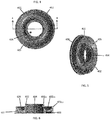
- a modified starter ball guide 401 for use in the SEC 1 of FIGS. 1-3 in particular is provided.
- a modified carrier support 601 for use in the SEC 1 of FIGS. 1-3 in particular is provided.
- the modified starter ball guide 401 includes a first side 402 and a second side 403 that opposes the first side 402.
- the modified starter ball guide 401 is also formed to define a first aperture 404 that extends through the modified starter ball guide 401 between the first side 402 and the second side 403.
- the modified starter ball guide 401 is rotatable about a central longitudinal axis of the first aperture 404.
- the first side 402 is formed to define an annular groove 405 that extends circumferentially about the first aperture 404.
- the first side 402 includes a steep-walled inner diameter 402 ID , a shallow-tapered outer diameter 402 OD and a curved central diameter 402 CD that is radially interposed between the steep-walled inner diameter 402 ID and the shallow-tapered outer diameter 402 OD to define the annular groove 405 such that the annular groove 405 tapers with increasing radial distance from the first aperture 404.
- the steep-walled inner diameter 402 ID may be taller than the shallow-tapered outer diameter 402 OD as measured from the surface of the annular groove 405.
- the carrier support 601 includes a first side 602 and a second side 603 that opposes the first side 602.
- the modified carrier support 601 is also formed to define a second aperture 604 that extends through the carrier support 601 between the first side 602 and the second side 603.
- the modified carrier support 601 is rotatable about a central longitudinal axis of the second aperture 604.
- the second side 603 of the carrier support 601 is formed to define pockets 605 that are circumferentially arrayed about the second aperture 604.
- the second side 603 includes a first planar surface 603 PS1 that defines a first plane P1, a second planar surface 603 PS2 that defines a second plane P2, an inwardly curving sidewall 603 SW that extends from an interior edge of the first planar surface 603 PS1 to the exterior edge of the second planar surface 603 PS2 and radial dividers 603 D .
- the radial dividers 603 D are oriented along the radial dimension of the second aperture 604 and extend toward the first planar surface 603 PS1 from the second planar surface 603 PS2 and radially inwardly from the inwardly curving sidewall 603 SW to delimit and define each of the pockets 605.
- the pockets 605 may be substantially uniformly arrayed in the circumferential dimension about the second aperture 604 with neighboring radial dividers 603 D cooperatively delimiting and defining respective ones of the pockets 605.
- the modified starter ball guide 401 and the modified carrier support 601 are disposable with respect to one another such that the first side 402 of the modified starter ball guide 401 faces the second side 602 of the modified carrier support 601.
- the modified starter ball guide 401 and the modified carrier support 601 are disposable with respect to one another at a distance DS at which engagement balls 1001 (e.g., the engagement balls 2 of FIGS. 1-3 ) are respectively retainable in corresponding ones of the pockets 605 and in a corresponding circumferential segment of the annular groove 405.
- each pocket 605 has a depth DP which is at least equal or greater than a radius of the engagement balls 1001 and a circumferential width W which exceeds a diameter of the engagement balls 1001. At least the depth DP of each pocket 605 insures full contact between the engagement balls 1001 and the circumferential face of each of the radial dividers 603 D .
- a profile of the second side 602 of the carrier support 601 at each of the pockets 605 may at least partially mimic a complementary profile of the first side 402 of the starter ball guide 401 at the annular groove 405. That is, while the second planar surface 603 PS2 and the inwardly curving sidewall 603 SW of the second side 602 of the carrier support 601 extend and curve around the curved central diameter 402 CD and the shallow-tapered outer diameter 402 OD of the first side 402 of the starter ball guide 401, the radial dividers 603 D fit into the corresponding circumferential segment of the annular groove 405.
- a tapering of a distal edge of each of the radial dividers 603 D (i.e., the profile of each of the radial dividers 603 D ) mimics or substantially follows a taper of the shallow-tapered outer diameter 402 OD .
Landscapes
- Engineering & Computer Science (AREA)
- General Engineering & Computer Science (AREA)
- Mechanical Engineering (AREA)
- One-Way And Automatic Clutches, And Combinations Of Different Clutches (AREA)
- Transmission Devices (AREA)
Applications Claiming Priority (1)
| Application Number | Priority Date | Filing Date | Title |
|---|---|---|---|
| US15/906,442 US10612608B2 (en) | 2018-02-27 | 2018-02-27 | Ball retention assembly for synchronous engagement clutch |
Publications (2)
| Publication Number | Publication Date |
|---|---|
| EP3534027A1 true EP3534027A1 (de) | 2019-09-04 |
| EP3534027B1 EP3534027B1 (de) | 2020-12-02 |
Family
ID=65529544
Family Applications (1)
| Application Number | Title | Priority Date | Filing Date |
|---|---|---|---|
| EP19158856.5A Active EP3534027B1 (de) | 2018-02-27 | 2019-02-22 | Kugelhalteanordnung für kupplung mit synchroner einrastung |
Country Status (2)
| Country | Link |
|---|---|
| US (1) | US10612608B2 (de) |
| EP (1) | EP3534027B1 (de) |
Cited By (1)
| Publication number | Priority date | Publication date | Assignee | Title |
|---|---|---|---|---|
| EP3561333B1 (de) * | 2018-04-26 | 2022-07-13 | Hamilton Sundstrand Corporation | Synchronkupplung |
Families Citing this family (1)
| Publication number | Priority date | Publication date | Assignee | Title |
|---|---|---|---|---|
| US20250376949A1 (en) * | 2024-06-05 | 2025-12-11 | Hamilton Sundstrand Corporation | Integral turbine wheel to clutch |
Citations (3)
| Publication number | Priority date | Publication date | Assignee | Title |
|---|---|---|---|---|
| GB866046A (en) * | 1958-04-09 | 1961-04-26 | United Aircraft Corp | Clutch mechanism for connecting a rotary driving member with a rotary driven member |
| US4322985A (en) * | 1980-03-20 | 1982-04-06 | Facet Enterprises, Inc. | Engine starter with an overrunning clutch device |
| EP0592352A2 (de) * | 1992-10-05 | 1994-04-13 | United Technologies Corporation | Fliehkraftkupplung |
Family Cites Families (6)
| Publication number | Priority date | Publication date | Assignee | Title |
|---|---|---|---|---|
| US3184025A (en) * | 1963-08-30 | 1965-05-18 | Twin Disc Clutch Co | Centrifugally operated actuating mechanism |
| US5496154A (en) * | 1994-04-18 | 1996-03-05 | General Motors Corporation | Fan drive with high torque release |
| EP1143162B1 (de) * | 1999-10-14 | 2008-04-23 | JTEKT Corporation | Kupplung |
| US7014026B2 (en) * | 2001-06-07 | 2006-03-21 | Drussel Wilfley Design, L.L.C. | Manual/automatic pressure control mechanism for centrifugal clutch |
| US7810624B1 (en) * | 2010-01-28 | 2010-10-12 | Drussel Wilfley Design Llc | Centrifugal clutch with expansion ring assembly |
| US9157494B2 (en) | 2013-08-07 | 2015-10-13 | Honeywell International Inc. | Centrifugal engagement and disengagement drive systems |
-
2018
- 2018-02-27 US US15/906,442 patent/US10612608B2/en active Active
-
2019
- 2019-02-22 EP EP19158856.5A patent/EP3534027B1/de active Active
Patent Citations (3)
| Publication number | Priority date | Publication date | Assignee | Title |
|---|---|---|---|---|
| GB866046A (en) * | 1958-04-09 | 1961-04-26 | United Aircraft Corp | Clutch mechanism for connecting a rotary driving member with a rotary driven member |
| US4322985A (en) * | 1980-03-20 | 1982-04-06 | Facet Enterprises, Inc. | Engine starter with an overrunning clutch device |
| EP0592352A2 (de) * | 1992-10-05 | 1994-04-13 | United Technologies Corporation | Fliehkraftkupplung |
Cited By (1)
| Publication number | Priority date | Publication date | Assignee | Title |
|---|---|---|---|---|
| EP3561333B1 (de) * | 2018-04-26 | 2022-07-13 | Hamilton Sundstrand Corporation | Synchronkupplung |
Also Published As
| Publication number | Publication date |
|---|---|
| EP3534027B1 (de) | 2020-12-02 |
| US10612608B2 (en) | 2020-04-07 |
| US20190264761A1 (en) | 2019-08-29 |
Similar Documents
| Publication | Publication Date | Title |
|---|---|---|
| US5257685A (en) | Pawl and ratchet clutch with shifting pawl | |
| US10890245B2 (en) | Epicyclic gear train | |
| CN108661807B (zh) | 用于燃气涡轮发动机的附件变速箱的输出组件 | |
| JP4906465B2 (ja) | ガスタービンエンジン組立体及びそれを組み立てる方法 | |
| US8899910B2 (en) | Air turbine starter and method for venting without loss of oil | |
| EP3266991B1 (de) | Untersetzungsgetriebe eines gasturbinenmotorstarters mit gestuften planetengetriebesätzen | |
| US20120111687A1 (en) | Roller pawl for use in ratchet and pawl style clutches | |
| CA2637277A1 (en) | Fan blade retaining structure | |
| JP2007113578A (ja) | ガスタービンエンジン組立体及びスプラインシステム | |
| US11808212B2 (en) | Drive shaft comprising a fusible section and method for protecting such a drive shaft against an overtorque | |
| EP3534027B1 (de) | Kugelhalteanordnung für kupplung mit synchroner einrastung | |
| US20180030900A1 (en) | Air Turbine Starter with Integrated Motor for Main Engine Cooling | |
| EP3266992A1 (de) | Untersetzungsgetriebe eines anlassers eines gasturbinentriebwerks mit einem rotierenden getriebeaktuator | |
| EP2961970B1 (de) | Gasturbinenanordnung sowie verfahren zur steuerung der rotation eines gasturbinenfans | |
| US5246094A (en) | Pawl and ratchet clutch having pawl with shifting center of gravity | |
| US5419420A (en) | Flyweight actuated clutch | |
| US8839927B2 (en) | Pawl stop for use in ratchet and pawl style clutch | |
| EP3267013B1 (de) | Gasturbinenmotoranlasseruntersetzungsgetriebe mit drehgetriebe und planetengetriebe-schaltgetriebe | |
| US11668244B2 (en) | Decoupler for engine starter | |
| EP3209873B1 (de) | Zubehörbaugruppe eines turbinenmotors | |
| CN112105842B (zh) | 用于变矩器的可变间距定子 | |
| US10895310B2 (en) | Side plate to stator attachment for torque converter | |
| JP2018096301A (ja) | ガスタービンエンジンの始動装置 | |
| JPS6314123Y2 (de) | ||
| KR102888599B1 (ko) | 베어링 지지 구조체를 갖는 공기 터빈 스타터 |
Legal Events
| Date | Code | Title | Description |
|---|---|---|---|
| PUAI | Public reference made under article 153(3) epc to a published international application that has entered the european phase |
Free format text: ORIGINAL CODE: 0009012 |
|
| STAA | Information on the status of an ep patent application or granted ep patent |
Free format text: STATUS: THE APPLICATION HAS BEEN PUBLISHED |
|
| AK | Designated contracting states |
Kind code of ref document: A1 Designated state(s): AL AT BE BG CH CY CZ DE DK EE ES FI FR GB GR HR HU IE IS IT LI LT LU LV MC MK MT NL NO PL PT RO RS SE SI SK SM TR |
|
| AX | Request for extension of the european patent |
Extension state: BA ME |
|
| STAA | Information on the status of an ep patent application or granted ep patent |
Free format text: STATUS: REQUEST FOR EXAMINATION WAS MADE |
|
| 17P | Request for examination filed |
Effective date: 20191213 |
|
| RBV | Designated contracting states (corrected) |
Designated state(s): AL AT BE BG CH CY CZ DE DK EE ES FI FR GB GR HR HU IE IS IT LI LT LU LV MC MK MT NL NO PL PT RO RS SE SI SK SM TR |
|
| GRAP | Despatch of communication of intention to grant a patent |
Free format text: ORIGINAL CODE: EPIDOSNIGR1 |
|
| STAA | Information on the status of an ep patent application or granted ep patent |
Free format text: STATUS: GRANT OF PATENT IS INTENDED |
|
| INTG | Intention to grant announced |
Effective date: 20200626 |
|
| RIN1 | Information on inventor provided before grant (corrected) |
Inventor name: LEBEAU, ERIK D. Inventor name: NI, WEISHUN WILLAIM |
|
| GRAS | Grant fee paid |
Free format text: ORIGINAL CODE: EPIDOSNIGR3 |
|
| GRAA | (expected) grant |
Free format text: ORIGINAL CODE: 0009210 |
|
| STAA | Information on the status of an ep patent application or granted ep patent |
Free format text: STATUS: THE PATENT HAS BEEN GRANTED |
|
| AK | Designated contracting states |
Kind code of ref document: B1 Designated state(s): AL AT BE BG CH CY CZ DE DK EE ES FI FR GB GR HR HU IE IS IT LI LT LU LV MC MK MT NL NO PL PT RO RS SE SI SK SM TR |
|
| REG | Reference to a national code |
Ref country code: GB Ref legal event code: FG4D |
|
| REG | Reference to a national code |
Ref country code: CH Ref legal event code: EP Ref country code: AT Ref legal event code: REF Ref document number: 1341255 Country of ref document: AT Kind code of ref document: T Effective date: 20201215 |
|
| REG | Reference to a national code |
Ref country code: IE Ref legal event code: FG4D |
|
| REG | Reference to a national code |
Ref country code: DE Ref legal event code: R096 Ref document number: 602019001517 Country of ref document: DE |
|
| PG25 | Lapsed in a contracting state [announced via postgrant information from national office to epo] |
Ref country code: FI Free format text: LAPSE BECAUSE OF FAILURE TO SUBMIT A TRANSLATION OF THE DESCRIPTION OR TO PAY THE FEE WITHIN THE PRESCRIBED TIME-LIMIT Effective date: 20201202 Ref country code: RS Free format text: LAPSE BECAUSE OF FAILURE TO SUBMIT A TRANSLATION OF THE DESCRIPTION OR TO PAY THE FEE WITHIN THE PRESCRIBED TIME-LIMIT Effective date: 20201202 Ref country code: GR Free format text: LAPSE BECAUSE OF FAILURE TO SUBMIT A TRANSLATION OF THE DESCRIPTION OR TO PAY THE FEE WITHIN THE PRESCRIBED TIME-LIMIT Effective date: 20210303 Ref country code: NO Free format text: LAPSE BECAUSE OF FAILURE TO SUBMIT A TRANSLATION OF THE DESCRIPTION OR TO PAY THE FEE WITHIN THE PRESCRIBED TIME-LIMIT Effective date: 20210302 |
|
| REG | Reference to a national code |
Ref country code: NL Ref legal event code: MP Effective date: 20201202 |
|
| REG | Reference to a national code |
Ref country code: AT Ref legal event code: MK05 Ref document number: 1341255 Country of ref document: AT Kind code of ref document: T Effective date: 20201202 |
|
| PG25 | Lapsed in a contracting state [announced via postgrant information from national office to epo] |
Ref country code: BG Free format text: LAPSE BECAUSE OF FAILURE TO SUBMIT A TRANSLATION OF THE DESCRIPTION OR TO PAY THE FEE WITHIN THE PRESCRIBED TIME-LIMIT Effective date: 20210302 Ref country code: SE Free format text: LAPSE BECAUSE OF FAILURE TO SUBMIT A TRANSLATION OF THE DESCRIPTION OR TO PAY THE FEE WITHIN THE PRESCRIBED TIME-LIMIT Effective date: 20201202 Ref country code: LV Free format text: LAPSE BECAUSE OF FAILURE TO SUBMIT A TRANSLATION OF THE DESCRIPTION OR TO PAY THE FEE WITHIN THE PRESCRIBED TIME-LIMIT Effective date: 20201202 Ref country code: PL Free format text: LAPSE BECAUSE OF FAILURE TO SUBMIT A TRANSLATION OF THE DESCRIPTION OR TO PAY THE FEE WITHIN THE PRESCRIBED TIME-LIMIT Effective date: 20201202 |
|
| PG25 | Lapsed in a contracting state [announced via postgrant information from national office to epo] |
Ref country code: HR Free format text: LAPSE BECAUSE OF FAILURE TO SUBMIT A TRANSLATION OF THE DESCRIPTION OR TO PAY THE FEE WITHIN THE PRESCRIBED TIME-LIMIT Effective date: 20201202 Ref country code: NL Free format text: LAPSE BECAUSE OF FAILURE TO SUBMIT A TRANSLATION OF THE DESCRIPTION OR TO PAY THE FEE WITHIN THE PRESCRIBED TIME-LIMIT Effective date: 20201202 |
|
| REG | Reference to a national code |
Ref country code: LT Ref legal event code: MG9D |
|
| PG25 | Lapsed in a contracting state [announced via postgrant information from national office to epo] |
Ref country code: LT Free format text: LAPSE BECAUSE OF FAILURE TO SUBMIT A TRANSLATION OF THE DESCRIPTION OR TO PAY THE FEE WITHIN THE PRESCRIBED TIME-LIMIT Effective date: 20201202 Ref country code: PT Free format text: LAPSE BECAUSE OF FAILURE TO SUBMIT A TRANSLATION OF THE DESCRIPTION OR TO PAY THE FEE WITHIN THE PRESCRIBED TIME-LIMIT Effective date: 20210405 Ref country code: RO Free format text: LAPSE BECAUSE OF FAILURE TO SUBMIT A TRANSLATION OF THE DESCRIPTION OR TO PAY THE FEE WITHIN THE PRESCRIBED TIME-LIMIT Effective date: 20201202 Ref country code: SK Free format text: LAPSE BECAUSE OF FAILURE TO SUBMIT A TRANSLATION OF THE DESCRIPTION OR TO PAY THE FEE WITHIN THE PRESCRIBED TIME-LIMIT Effective date: 20201202 Ref country code: SM Free format text: LAPSE BECAUSE OF FAILURE TO SUBMIT A TRANSLATION OF THE DESCRIPTION OR TO PAY THE FEE WITHIN THE PRESCRIBED TIME-LIMIT Effective date: 20201202 Ref country code: EE Free format text: LAPSE BECAUSE OF FAILURE TO SUBMIT A TRANSLATION OF THE DESCRIPTION OR TO PAY THE FEE WITHIN THE PRESCRIBED TIME-LIMIT Effective date: 20201202 Ref country code: CZ Free format text: LAPSE BECAUSE OF FAILURE TO SUBMIT A TRANSLATION OF THE DESCRIPTION OR TO PAY THE FEE WITHIN THE PRESCRIBED TIME-LIMIT Effective date: 20201202 |
|
| PG25 | Lapsed in a contracting state [announced via postgrant information from national office to epo] |
Ref country code: AT Free format text: LAPSE BECAUSE OF FAILURE TO SUBMIT A TRANSLATION OF THE DESCRIPTION OR TO PAY THE FEE WITHIN THE PRESCRIBED TIME-LIMIT Effective date: 20201202 |
|
| REG | Reference to a national code |
Ref country code: DE Ref legal event code: R097 Ref document number: 602019001517 Country of ref document: DE |
|
| PG25 | Lapsed in a contracting state [announced via postgrant information from national office to epo] |
Ref country code: IS Free format text: LAPSE BECAUSE OF FAILURE TO SUBMIT A TRANSLATION OF THE DESCRIPTION OR TO PAY THE FEE WITHIN THE PRESCRIBED TIME-LIMIT Effective date: 20210402 Ref country code: MC Free format text: LAPSE BECAUSE OF FAILURE TO SUBMIT A TRANSLATION OF THE DESCRIPTION OR TO PAY THE FEE WITHIN THE PRESCRIBED TIME-LIMIT Effective date: 20201202 |
|
| PLBE | No opposition filed within time limit |
Free format text: ORIGINAL CODE: 0009261 |
|
| STAA | Information on the status of an ep patent application or granted ep patent |
Free format text: STATUS: NO OPPOSITION FILED WITHIN TIME LIMIT |
|
| REG | Reference to a national code |
Ref country code: BE Ref legal event code: MM Effective date: 20210228 |
|
| PG25 | Lapsed in a contracting state [announced via postgrant information from national office to epo] |
Ref country code: AL Free format text: LAPSE BECAUSE OF FAILURE TO SUBMIT A TRANSLATION OF THE DESCRIPTION OR TO PAY THE FEE WITHIN THE PRESCRIBED TIME-LIMIT Effective date: 20201202 Ref country code: IT Free format text: LAPSE BECAUSE OF FAILURE TO SUBMIT A TRANSLATION OF THE DESCRIPTION OR TO PAY THE FEE WITHIN THE PRESCRIBED TIME-LIMIT Effective date: 20201202 Ref country code: LU Free format text: LAPSE BECAUSE OF NON-PAYMENT OF DUE FEES Effective date: 20210222 |
|
| 26N | No opposition filed |
Effective date: 20210903 |
|
| PG25 | Lapsed in a contracting state [announced via postgrant information from national office to epo] |
Ref country code: DK Free format text: LAPSE BECAUSE OF FAILURE TO SUBMIT A TRANSLATION OF THE DESCRIPTION OR TO PAY THE FEE WITHIN THE PRESCRIBED TIME-LIMIT Effective date: 20201202 Ref country code: SI Free format text: LAPSE BECAUSE OF FAILURE TO SUBMIT A TRANSLATION OF THE DESCRIPTION OR TO PAY THE FEE WITHIN THE PRESCRIBED TIME-LIMIT Effective date: 20201202 |
|
| PG25 | Lapsed in a contracting state [announced via postgrant information from national office to epo] |
Ref country code: ES Free format text: LAPSE BECAUSE OF FAILURE TO SUBMIT A TRANSLATION OF THE DESCRIPTION OR TO PAY THE FEE WITHIN THE PRESCRIBED TIME-LIMIT Effective date: 20201202 Ref country code: IE Free format text: LAPSE BECAUSE OF NON-PAYMENT OF DUE FEES Effective date: 20210222 |
|
| PG25 | Lapsed in a contracting state [announced via postgrant information from national office to epo] |
Ref country code: IS Free format text: LAPSE BECAUSE OF FAILURE TO SUBMIT A TRANSLATION OF THE DESCRIPTION OR TO PAY THE FEE WITHIN THE PRESCRIBED TIME-LIMIT Effective date: 20210402 |
|
| PG25 | Lapsed in a contracting state [announced via postgrant information from national office to epo] |
Ref country code: BE Free format text: LAPSE BECAUSE OF NON-PAYMENT OF DUE FEES Effective date: 20210228 |
|
| REG | Reference to a national code |
Ref country code: CH Ref legal event code: PL |
|
| PG25 | Lapsed in a contracting state [announced via postgrant information from national office to epo] |
Ref country code: LI Free format text: LAPSE BECAUSE OF NON-PAYMENT OF DUE FEES Effective date: 20220228 Ref country code: CH Free format text: LAPSE BECAUSE OF NON-PAYMENT OF DUE FEES Effective date: 20220228 |
|
| P01 | Opt-out of the competence of the unified patent court (upc) registered |
Effective date: 20230522 |
|
| PG25 | Lapsed in a contracting state [announced via postgrant information from national office to epo] |
Ref country code: CY Free format text: LAPSE BECAUSE OF FAILURE TO SUBMIT A TRANSLATION OF THE DESCRIPTION OR TO PAY THE FEE WITHIN THE PRESCRIBED TIME-LIMIT Effective date: 20201202 |
|
| PG25 | Lapsed in a contracting state [announced via postgrant information from national office to epo] |
Ref country code: HU Free format text: LAPSE BECAUSE OF FAILURE TO SUBMIT A TRANSLATION OF THE DESCRIPTION OR TO PAY THE FEE WITHIN THE PRESCRIBED TIME-LIMIT; INVALID AB INITIO Effective date: 20190222 |
|
| PG25 | Lapsed in a contracting state [announced via postgrant information from national office to epo] |
Ref country code: MK Free format text: LAPSE BECAUSE OF FAILURE TO SUBMIT A TRANSLATION OF THE DESCRIPTION OR TO PAY THE FEE WITHIN THE PRESCRIBED TIME-LIMIT Effective date: 20201202 |
|
| PG25 | Lapsed in a contracting state [announced via postgrant information from national office to epo] |
Ref country code: TR Free format text: LAPSE BECAUSE OF FAILURE TO SUBMIT A TRANSLATION OF THE DESCRIPTION OR TO PAY THE FEE WITHIN THE PRESCRIBED TIME-LIMIT Effective date: 20201202 |
|
| PG25 | Lapsed in a contracting state [announced via postgrant information from national office to epo] |
Ref country code: MT Free format text: LAPSE BECAUSE OF FAILURE TO SUBMIT A TRANSLATION OF THE DESCRIPTION OR TO PAY THE FEE WITHIN THE PRESCRIBED TIME-LIMIT Effective date: 20201202 |
|
| PGFP | Annual fee paid to national office [announced via postgrant information from national office to epo] |
Ref country code: GB Payment date: 20260121 Year of fee payment: 8 |
|
| PGFP | Annual fee paid to national office [announced via postgrant information from national office to epo] |
Ref country code: DE Payment date: 20260121 Year of fee payment: 8 |
|
| PGFP | Annual fee paid to national office [announced via postgrant information from national office to epo] |
Ref country code: FR Payment date: 20260121 Year of fee payment: 8 |