EP3534112A2 - Procédé de détermination d'une représentation utile électronique d'un environnement, dispositif correspondant, support de données - Google Patents
Procédé de détermination d'une représentation utile électronique d'un environnement, dispositif correspondant, support de données Download PDFInfo
- Publication number
- EP3534112A2 EP3534112A2 EP19160541.9A EP19160541A EP3534112A2 EP 3534112 A2 EP3534112 A2 EP 3534112A2 EP 19160541 A EP19160541 A EP 19160541A EP 3534112 A2 EP3534112 A2 EP 3534112A2
- Authority
- EP
- European Patent Office
- Prior art keywords
- data
- reliability
- environment
- feature
- features
- Prior art date
- Legal status (The legal status is an assumption and is not a legal conclusion. Google has not performed a legal analysis and makes no representation as to the accuracy of the status listed.)
- Granted
Links
Images


Classifications
-
- G—PHYSICS
- G01—MEASURING; TESTING
- G01C—MEASURING DISTANCES, LEVELS OR BEARINGS; SURVEYING; NAVIGATION; GYROSCOPIC INSTRUMENTS; PHOTOGRAMMETRY OR VIDEOGRAMMETRY
- G01C21/00—Navigation; Navigational instruments not provided for in groups G01C1/00 - G01C19/00
- G01C21/38—Electronic maps specially adapted for navigation; Updating thereof
- G01C21/3863—Structures of map data
- G01C21/387—Organisation of map data, e.g. version management or database structures
- G01C21/3881—Tile-based structures
-
- G—PHYSICS
- G01—MEASURING; TESTING
- G01C—MEASURING DISTANCES, LEVELS OR BEARINGS; SURVEYING; NAVIGATION; GYROSCOPIC INSTRUMENTS; PHOTOGRAMMETRY OR VIDEOGRAMMETRY
- G01C11/00—Photogrammetry or videogrammetry, e.g. stereogrammetry; Photographic surveying
- G01C11/04—Interpretation of pictures
-
- G—PHYSICS
- G01—MEASURING; TESTING
- G01C—MEASURING DISTANCES, LEVELS OR BEARINGS; SURVEYING; NAVIGATION; GYROSCOPIC INSTRUMENTS; PHOTOGRAMMETRY OR VIDEOGRAMMETRY
- G01C15/00—Surveying instruments or accessories not provided for in groups G01C1/00 - G01C13/00
- G01C15/002—Active optical surveying means
-
- G—PHYSICS
- G01—MEASURING; TESTING
- G01C—MEASURING DISTANCES, LEVELS OR BEARINGS; SURVEYING; NAVIGATION; GYROSCOPIC INSTRUMENTS; PHOTOGRAMMETRY OR VIDEOGRAMMETRY
- G01C21/00—Navigation; Navigational instruments not provided for in groups G01C1/00 - G01C19/00
- G01C21/005—Navigation; Navigational instruments not provided for in groups G01C1/00 - G01C19/00 with correlation of navigation data from several sources, e.g. map or contour matching
-
- G—PHYSICS
- G01—MEASURING; TESTING
- G01C—MEASURING DISTANCES, LEVELS OR BEARINGS; SURVEYING; NAVIGATION; GYROSCOPIC INSTRUMENTS; PHOTOGRAMMETRY OR VIDEOGRAMMETRY
- G01C21/00—Navigation; Navigational instruments not provided for in groups G01C1/00 - G01C19/00
- G01C21/20—Instruments for performing navigational calculations
-
- G—PHYSICS
- G01—MEASURING; TESTING
- G01S—RADIO DIRECTION-FINDING; RADIO NAVIGATION; DETERMINING DISTANCE OR VELOCITY BY USE OF RADIO WAVES; LOCATING OR PRESENCE-DETECTING BY USE OF THE REFLECTION OR RERADIATION OF RADIO WAVES; ANALOGOUS ARRANGEMENTS USING OTHER WAVES
- G01S17/00—Systems using the reflection or reradiation of electromagnetic waves other than radio waves, e.g. lidar systems
- G01S17/02—Systems using the reflection of electromagnetic waves other than radio waves
- G01S17/06—Systems determining position data of a target
- G01S17/42—Simultaneous measurement of distance and other co-ordinates
-
- G—PHYSICS
- G01—MEASURING; TESTING
- G01S—RADIO DIRECTION-FINDING; RADIO NAVIGATION; DETERMINING DISTANCE OR VELOCITY BY USE OF RADIO WAVES; LOCATING OR PRESENCE-DETECTING BY USE OF THE REFLECTION OR RERADIATION OF RADIO WAVES; ANALOGOUS ARRANGEMENTS USING OTHER WAVES
- G01S17/00—Systems using the reflection or reradiation of electromagnetic waves other than radio waves, e.g. lidar systems
- G01S17/88—Lidar systems specially adapted for specific applications
- G01S17/89—Lidar systems specially adapted for specific applications for mapping or imaging
-
- G—PHYSICS
- G01—MEASURING; TESTING
- G01S—RADIO DIRECTION-FINDING; RADIO NAVIGATION; DETERMINING DISTANCE OR VELOCITY BY USE OF RADIO WAVES; LOCATING OR PRESENCE-DETECTING BY USE OF THE REFLECTION OR RERADIATION OF RADIO WAVES; ANALOGOUS ARRANGEMENTS USING OTHER WAVES
- G01S7/00—Details of systems according to groups G01S13/00, G01S15/00, G01S17/00
- G01S7/48—Details of systems according to groups G01S13/00, G01S15/00, G01S17/00 of systems according to group G01S17/00
- G01S7/4808—Evaluating distance, position or velocity data
-
- G—PHYSICS
- G05—CONTROLLING; REGULATING
- G05D—SYSTEMS FOR CONTROLLING OR REGULATING NON-ELECTRIC VARIABLES
- G05D1/00—Control of position, course, altitude or attitude of land, water, air or space vehicles, e.g. using automatic pilots
- G05D1/02—Control of position or course in two dimensions
- G05D1/021—Control of position or course in two dimensions specially adapted to land vehicles
- G05D1/0231—Control of position or course in two dimensions specially adapted to land vehicles using optical position detecting means
- G05D1/0238—Control of position or course in two dimensions specially adapted to land vehicles using optical position detecting means using obstacle or wall sensors
- G05D1/024—Control of position or course in two dimensions specially adapted to land vehicles using optical position detecting means using obstacle or wall sensors in combination with a laser
-
- G—PHYSICS
- G05—CONTROLLING; REGULATING
- G05D—SYSTEMS FOR CONTROLLING OR REGULATING NON-ELECTRIC VARIABLES
- G05D1/00—Control of position, course, altitude or attitude of land, water, air or space vehicles, e.g. using automatic pilots
- G05D1/02—Control of position or course in two dimensions
- G05D1/021—Control of position or course in two dimensions specially adapted to land vehicles
- G05D1/0268—Control of position or course in two dimensions specially adapted to land vehicles using internal positioning means
- G05D1/0274—Control of position or course in two dimensions specially adapted to land vehicles using internal positioning means using mapping information stored in a memory device
Definitions
- the invention relates to a method for determining an electronically usable representation of an environment, a device for this and a data carrier according to the preambles of the independent claims. It can be used in the field of control of autonomously moving objects, such as autonomous vehicles and aircraft / drones, mobile robots and the like. It concerns the construction of representations of environments in which moving objects can move and the use of such representations.
- such representations can be understood as maps that are, however, extended to include certain features and information.
- the maps can be created two-dimensionally, for example to map the trafficability of a particular terrain, or three-dimensionally to characterize the space available for robotics or aircraft movements.
- the following description exemplifies two-dimensional representations / mappings. However, this is not intended to exclude the application of the invention to three-dimensional representations.
- a representation type are so-called "gridmaps". They roughly correspond to the "bitmaps" of graphics. Gridmaps can span a tiled surface, where the tile size is the smallest unit and corresponds to the possible spatial resolution. For each tile information can be stored, which represent the environment in the place of the tile. In particular, entries for obstacles can be stored. Obstacles and generally mapped objects are also referred to as “features” below.
- Another way of presenting is a vector representation according to graphic vector graphics.
- a technique alternative to mapping real environmental features in an environmental representation is the representation of custom reflectors in reflector maps rather than the representation of real objects.
- real objects of the scenery are mapped, but purposefully attached detection targets (reflectors), which are then mapped.
- the mapping of reflector targets can also be done in a gridmap or vectorially.
- Autonomous vehicles usually include scanners that allow them to capture the environment around them. As a rule, they can scan the surroundings with a certain resolution in a full circle around them. This gives you a survey of the environment that tells you in what direction and how far away obstacles were detected.
- the angular resolution can be ⁇ 1 ° or ⁇ 2 ° or ⁇ 5 ° or ⁇ 10 °. During a measurement, data pairs are produced in this way, which in each case indicate the distance of an obstacle relative to the vehicle orientation relative to a relative angular position.
- corresponding representations indicate occupancy probabilities of tiles that have been ascertained spatially resolved and maintained in tiles.
- the occupancy probability thus indicates with what probability an obstacle / feature is present at a predetermined position.
- the occupancy probabilities can then be used to weight several measurements among one another.
- the object of the invention is to provide an improved electronically usable environmental representation. Also provided is a method for determining such a representation, and an apparatus therefor.
- One aspect of the invention is an environment representation device comprising a data carrier and an interface device, wherein the data carrier carries data representing an environment, with one or more first data carrier parts, carrying map data parts that indicate location-resolving features of an environment or permit the derivation of such feature information, and with one or more second data carrier parts bearing reliability data parts which spatially indicate reliability data of features of an environment or allow the derivation of such reliability data and indicate the location resolution as to how reliably detectable the respectively represented characteristics were estimated, and wherein the interface device map data and reliability data spatially resolving each other assigned read and / or write accessibility.
- the environment representation device makes use of the knowledge that the storage of spatially resolved reliability data enables improved position determination and improved path planning, since, for example, areas of faulty map areas can be known. Likewise, map areas can be known which are correct with a high level of reliability, so that, for example, when determining the position, these map areas can then be "trusted". Moreover, the reliability data also allow for further improvements in the operation of eg an autonomous vehicle, as explained later.
- the reliability data may indicate the reliability with which a respective feature is actually present at a location of the card.
- the reliability is very high (i.e., 1 or close to 1). Recognize e.g. only 50% of the measurements are an obstacle / feature, the reliability may be lower, e.g. only 0.5. If the same result is obtained in even less measurements, i. it is e.g. For example, if only 10% of the measurements detected an obstacle / feature, the reliability could be only 0.1.
- a level of a measurement signal can also be used to determine the reliability. This level can be, e.g. in a laser scanner, for transparent features to be lower, which is associated with a lower reliability.
- the map data parts represent presence probabilities which indicate spatially resolving presence probabilities of features of an environment or allow the derivation of such presence probabilities and indicate the spatially resolving ones as to how likely a given feature was estimated.
- the difference between the presence probability and the reliability is thus in particular that the presence probability relates to the probability with which a real feature actually exists, whereas the reliability relates in particular to the reliability of the acquisition / measurement of an existing feature / object ( ie the scanner used eg for the measurement is taken into account in the reliability).
- the data carrier carries historical data parts, which specify spatially resolving detection histories of features of an environment or allow the derivation of such detection histories, and wherein the interface device and the Historical data makes the other data accessible spatially resolved.
- the historical data parts thus reflect the features recorded in the past in one place.
- the data carrier bears marking data parts which mark with spatial resolution, which of the reliability data and / or the map data should be changeable over time and which are not, and wherein the interface device also makes the marking data accessible to the other data with spatial resolution. It can therefore be distinguished according to changeable and unchangeable reliability data and / or map data.
- Providing map data may include determining and / or updating and / or retrieving existing environmental representation data.
- the reliability data of individual feature areas can be determined on the basis of scatters of measured values of the same map areas determined in real time.
- the reliability data of individual feature areas are determined based on the age of previously determined measured values of identical map areas. In this case, older measured values can lead to a lower reliability.
- the reliability data of individual map areas can be manually entered and / or changed, preferably via a graphical user interface. This can be exploited that an operator with local knowledge can provide additional information about the reliability.
- the reliability data may be determined and / or changed during the use of an environmental representation in accordance with current measured values of a device or vehicle using the environment representation and according to historical data.
- the reliability data are accordingly not static, but in particular can be updated regularly.
- the feature data of the map data indicates, in a spatially resolving manner, a presence probability of a feature.
- Presence probabilities may be stored spatially resolving in addition to the reliability data.
- the spatially resolved presence probability values and the spatially resolved reliability values are stored separately and / or computed into a spatially resolved common parameter.
- the environmental representation preferably describes a two-dimensional surface or a three-dimensional volume. Both applications in the plane and in space (eg with drones) can be accessed in this way.
- the represented environment is logically subdivided into a plurality of (in particular equal) tiles, wherein the map data and the reliability data are tile-resolved or resolvable or interpolatable, where a tile may be associated or assignable to a data tuple that has at least one presence probability for that tile has a reliability value and optionally also an immutability tag.
- a plurality of known reflector points are mounted in the environment represented, wherein the map data and the reliability data are stored in a reflector-resolved or resolvable manner, wherein a reflector point is optionally also assigned or can be assigned an immutability designation.
- the reflector point may be e.g. to act an optical reflector.
- RFID Radio Frequency Identification
- the above values can each be used to determine the reliability.
- the current measured values are obtained by surveying the surroundings from the perspective of the mobile object, wherein the surveying comprises detecting a plurality of features of the environment and subjecting the measured values to temporal analysis.
- the reliability data are preferably determined in each case as a factor between 0 and 1 and / or as a logarithmic value between - ⁇ and 0.
- a device for carrying out the described method can be a single computer or a computer network, in particular a distributed system with at least temporarily mutually preferably wirelessly connected computers, wherein at least one of the computers is part of an autonomously navigating vehicle having sensors for environmental detection.
- the distributed system may be a peer-to-peer system or a server-client system, or a hybrid, such as a server, only for synchronizing / administrative activities.
- a data carrier having data thereon, which represent an environment, with map data parts that indicate location-resolving features of an environment or permit the derivation of such feature information, and with reliability data parts of individual specified features that are represented by the map data parts, wherein the reliability data indicate location-resolving, as to how reliably detectable each represented features can be considered.
- the correctness probability we thus preferably indicates the probability with which the position of the object (for example of the self-propelled vehicle) was correctly determined. In the correctness probability we can also enter the reliability values.
- the method is configured such that the evaluation in step c, even in accordance with a presence probability of an electronically detectable feature.
- the determination of an accuracy probability of each individual hypothetical detection can be made on the basis of a Gaussian distribution, in which the difference represents the abscissa and where the reliability value associated with a hypothetical feature is expressed as a factor between 0 and 1 in the exponent and / or at the Gaussian distribution can be taken into account.
- the total probability value wh may be derived by multiplying the individual evaluation results of the hypothetical acquisitions or by summing corresponding logarithmic values, in which case the reliability values associated with the respective hypothetical feature are taken as factors between 0 and 1 or corresponding logarithmic values Sum can be considered.
- the position determination comprises the selection of the positions of one of the hypothetical positions in accordance with the determined probability as an object position.
- the position which has the highest probability is selected as the object position.
- the position determination comprises a weighted offsetting of the positions of a plurality of the hypothetical positions, in particular in accordance with their determined probabilities.
- the rating can be done with a Monte Carlo algorithm.
- a path planning method for a moving object in an environment has the steps of (a) providing a digital representation of the environment representing a plurality of environmental features and for at least some of these features also indicating respective reliability values or allowing their derivation, (b) setting a waypoint as the first point of a path to be planned, (c) Choose one of the first point following and from this spatially spaced second point from a pathfinding criterion, (d) checking the second point and optionally other points for driveability using the digital representation including the specified reliability values, and (e) if the check satisfies a predetermined criterion, setting the second point as a further waypoint and as a new first point and continuing the method at (c), otherwise choosing another second point following the first point and spaced therefrom based on a pathfinding criterion and continuing the method at (d).
- the position determination method and the pathfinding method use an environment representation described above. And also to them performing devices and data carriers with appropriate according to individualized data are indicated.
- the device has, for example, a distributed system with at least temporarily preferably wirelessly connected computers, wherein at least one of the computers is part of an autonomously navigating vehicle that has sensors for environmental detection.
- features are electronically detectable objects that are relevant to the movement of an autonomously moving object, such as a moving vehicle, such as a movement obstacle. Also their image in a mapping / environment representation can be addressed with “feature”. These may be, for example, walls, shelf supports, doors, stored goods, other vehicles, persons, window surfaces, glazings, reflectors or the like - or their image in an environmental representation.
- Fig. 1 schematically shows a typical environment to be represented electronically usable. Shown is a wide aisle, the right kinks behind, rear door 13, on the right wall a roller shutter 12 and on the left wall of a shelf 14. He is surrounded by walls 11, a floor 15 and a ceiling 16. A person 17 moves in the corridor.
- the vehicle 50 has a surveying device 56, by means of which the vehicle environment can be measured.
- the surveying device 56 may, for example, detect obstacles around the vehicle or moving object present in a plane parallel to the floor 15 at the desired or predetermined or adjustable distance. It can have a LIDAR (Light Detection and Ranging) or LADAR (Laser Detection and Ranging), by means of which obstacles are detected in the desired angular or spatial resolution.
- the surveying device 56 can quickly scan preferably around the vehicle, or at least in one sector, in advance of the motion, thus generating data pairs of direction and distance to a backscattering feature. It can scan in one plane or even scan and measure the space three-dimensionally.
- Difficulties occur, for example, when the shelf 14 is marked safe in an electronic representation of the scene 10, but coincidentally when surveying the surroundings with the surveying device 56, the vertical supports of the shelf 14 were not hit so that only the wall behind it was detected .
- Similar difficulties arise when, in the map update, a person 17 has previously been recognized as a backscattering target and accordingly has led to certain map updates, but is absent from the current survey / scan and therefore does not cause backscatter.
- Similar difficulties arise with transparent obstacles, such as a glass door 13 or, generally, doors and gates 12, which can sometimes be open and sometimes closed.
- occupancy probabilities of tiles Presence probabilities of features / obstacles
- the shelf 14 or its supports can be regarded as constantly present and therefore has a probability of occupancy of 1. Nevertheless, its detection can fail for the reasons mentioned.
- a glass door 13 may occasionally be open and therefore may have an occupancy probability / probability of 0.9. However, the fact that it is made of glass makes it difficult to detect, so in fact it may not be detected regularly even when it is closed. The two examples mentioned concern detection difficulties of features (shelf 14, door 13).
- occupancy probabilities / presence probabilities can not give sufficiently meaningful data. Assuming, for example, that a particular area of the aisle is occupied by one person 5% of the time, and therefore the occupation or tiles associated with it are assigned an occupancy probability of 5% (0.05), this does not say anything about the dynamics or the frequency the changes in the busy state of the respective tiles.
- an environment representation besides the feature data (which may be, for example, yes / no information on tile occupancy or occupancy probabilities of tiles) also has reliability data indicating how reliably detectable a particular feature was viewed and evaluated.
- the reliability data can be given as a factor with an analog value between 0 (very unreliable) and 1 (very reliable).
- This standardization has the advantage that they can then be used in stochastic computing according to the usual stochastic rules.
- Fig. 2 shows schematically and qualitatively the assignment of reliability data to tiles of a scene which is roughly the same as that of the Fig. 1 equivalent. Not shown are the likewise available occupancy probabilities or assignments of the tiles of the scenery. Shown schematically is the top view of the in Fig. 1 shown gear. In addition, some reliability entries with letters are indicated schematically. With 11 'images of wall areas are indicated, which can be regarded as reliable present and detectable. The occupancy probability for this (not shown) would be 1 because the walls are stable, and the reliability data may also be set as 1 or very close to 1 (0.99).
- the occupancy probability of the associated tiles is 1 (100%) because the shelf is always present.
- the reliability may be less, about 0.8, as it may occasionally happen that a shelf support is not detected when surveying the environment by the surveying device 56, although it is present.
- the occupancy probability of the associated tiles is 95% (0.95).
- the door since the door is made of glass, it can often escape detection so that the associated reliability values can be, for example, 0.3.
- the associated reliability values 17 'or 12' can be comparatively high, for example 0.98, if the detection of these features can be comparatively reliable, while the occupancy probabilities can be low, for example 0.1.
- Fig. 2 are indicated with the A to E ranges of different reliability data. The same letters should not say that the reliability data are all the same. However, they take account of similar circumstances and can be very similar to each other.
- the use of the determined reliability values is carried out in such a way that they ultimately flow into the evaluation of current surveying results for the positioning or the evaluation of path points in the route planning.
- the design is such that more reliably valued features are weighted more heavily than unreliable valued features. As a result, as more reliably evaluated features dominate the result more strongly than more unreliable ones, so that final results are more likely to be correct, or are likely to be closer to the objectively correct value.
- the following is a method for determining an electronically usable representation of an environment.
- the representation represents features of the environment in a spatially resolved manner.
- the method has the steps of providing map data, determining reliability data, and storing the map data and the reliability data in spatially resolving, associated or assignable, environment representation.
- the provision of the map data may include redetermining map data or updating it or retrieving existing map data.
- map data feature representations are considered here, ie information about where in the represented environment a feature (obstacle) is present.
- the per-tile specification may be a plain yes / no (0/1), or a gradual probability of presence.
- the map data thus provided are assigned reliability data in a spatially resolved or spatially resolved manner.
- the reliability data has the quality described above. All data is then assigned spatially resolved or stored as a reference.
- the determination of the reliability values can be carried out once initializing and / or continuously during the real use of the data in a newly creating or updating manner. It may be provided a default assignment of reliability values, for example, sets 0.95 for all tiles. Based on this later changes can be made.
- the actual determination of the reliability data can be done in several different ways. They can, for example, be entered manually in a spatially resolving manner, for example via a graphical user interface.
- the tiles B of the image 14 'of the shelf 14 may be assigned a lower reliability than 1.
- Tiles A of images 11' of walls can be set to a very high reliability value (0.99 or 1). Other areas may receive different values according to their detectability.
- material data can also be entered or adopted in a spatially resolving manner, and reliability data can be assigned to this material data automatically or manually, for example by means of data. B high values close to or exactly 1 for conventional walls, lower values for reflective surfaces and low values close to 0 for glass surfaces of windows, gates or doors.
- Another way of determining the reliability data is to incorporate a time component into it, such that the reliability of represented features decreases over time, reflecting the experience that changes may occur over time.
- history data can continue to be stored in a spatially resolving manner that allows conclusions to be drawn about the course of the feature captures of the individual tiles.
- Another way of determining reliability data of features / tiles is to evaluate scatters in feature acquisitions of near-term surveys.
- “Timely” may mean that the time interval of the measurements should be ⁇ 20 min, ⁇ 10 min, ⁇ 5 min, ⁇ 2 min or ⁇ 1 min or ⁇ 30 s. If, at such closely spaced environmental measurements, different results appear in a particular mapped region (ie, spreads exceed a predetermined level), it is likely that these different results are due not to changes in the state of the environment but to the measurement same is unreliable.
- a vehicle 50 passes the shelf 14 also shown there and makes several measurements at intervals of 1 s and occasionally "sees" the shelf supports and occasionally not, because these supports tend to be filigree structures, scattering values will result in the area of the shelf 14. sometimes showing a presence and sometimes not. It can be deduced from such variations that there are unreliable traceable features at each location. The same applies, for example, to the detection of a glass door or glass surface.
- the saving Historical data also includes the storage of measurement histories, which in turn includes the caching of older surveys.
- the limitation of such histories may be on the basis of time (ie, anything that is older than a threshold, say 1 day or 1 hour or more than 1/2 hour or more than 10 minutes or older than 5 minutes) ) or storing a number of recent surveys (eg, 20 or 15 or 10 or 5 surveys) and replacing the oldest with the most recent one.
- Reliability values can also be assigned according to the type of generation of associated occupancy probabilities and then stored. Occupancy probabilities can, for example, be set or supplemented by special pattern recognition methods and / or pattern completion methods. Then, associated reliability data may, for example, be set to a certain default value, which may be different than possibly otherwise used default values, or the reliability values may be set in accordance with a previously made quantitative estimate of the reliability of the pattern recognition or completion.
- the standard deviation of the reflector centers determined from the individual measurements can be used as a measure of the reliability of the information.
- the reliability values can be variable and revised or updated with special procedures. This can be done, for example, in real time in accordance with data collected during the use of the environmental representation of useful moving objects 50.
- individual map areas areas of several tiles, features
- This immutability marker can also be set in a spatially resolving manner and assigned or assigned to be assigned.
- the reliability value of a feature may be stored, for example, as a value between 0 and 1 and used in this formatting and scaling in stochastic calculations. In principle, however, other memory formats are also conceivable. These must then be taken into account accordingly in the respective offsetting.
- the same applies to the presence probabilities. If presence probabilities and reliability data are spatially resolvable in a statistically calculable format, they can be spatially resolved to a common value and thus stored spatially resolved in addition to or instead of at least one of the Ausganshong. For example, if both are each stored as a statistical factor between 0 and 1, the offset may be a multiplication and the storage may then be e.g. B. as data triplets consisting of presence probability (Ex: 0.9), reliability value (Ex: 0.8) and the calculated value (for the examples 0.9 * 0.8 0.72) to the associated place.
- One aspect of the presentation of reliability values is also a device for representing an environment that cooperates with other devices that want to use the environment representation, such as for location, navigation / pathfinding or updating the same.
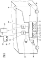
- the environment representative device 50 is shown schematically in FIG Fig. 5 shown.
- the hardware for implementing the described methods and method steps is usually a suitably programmed computer or a distributed system with multiple computers. If a distributed system is provided, it can be a peer-to-peer system, so a system of several similar computers, which are at least temporarily connected wirelessly and / or circuit-based, or it may be a server / client system in which the functions are distributed appropriately. Mixed forms for this purpose are also conceivable, for example such that the essential method steps in the individual vehicles 50, 50 'are made and a central server 57 carries out synchronizations.
- the vehicle 50 has a memory 51 in which the previously mentioned data is stored.
- memory 51 in which the previously mentioned data is stored.
- Several memory areas 51a to 51e are indicated, this being only a graphical representation and not necessarily being an image of the data and memory structure actually present.
- 51a symbolizes the storage of map data parts, ie information on features / obstacles.
- 51b symbolizes the storage of the reliability data z. B. in the format described above.
- 51c symbolizes the storage of historical data, as already shown.
- 51d symbolizes the storage of markers for the variability of certain data.
- 51e symbolizes a buffer for temporary storage of surveying results, for example.
- Other memory areas may be provided according to the needs of the digital equipment.
- the spatial resolution of the individual data parts can be the same or different from each other. If different, interpolations can be made to match or fine finite data can be mapped to "nearby" coarser grid data.
- the interface device 52 can make the necessary spatially resolving assignments of the data parts during readout, if the assignments do not result from the memory structure anyway.
- the interface device can also be used during Read out possibly necessary conversion of respective vector data, if that is the storage format of the data, into geographically distributed gridmap data and vice versa to work at reading.
- the interface device 52 can also have interfaces to the other system-necessary parts, such as connectors 53 for wired communication, which can be used at least temporarily, a peer-to-peer interface 55, a server-client interface 54 and a connection towards Measuring device 56.
- the peer-to-peer interface 55 and the server-client interface 54 may be wireless and technically the same interface, for example a radio link used with different addresses. But they can also be technically different, depending on technical needs such as bandwidth, reliability, range and the like.
- the measuring device 56 serves to measure the surroundings of the vehicle. This may be the already mentioned LIDAR or LADAR. But also image processing, especially stereoscopic, is conceivable. It is designed to capture the environment at least in the direction of travel ahead and preferably completely around the vehicle and to recognize features according to direction and distance. The device 56 can operate largely autonomously and periodically measure the environment. Here are the already mentioned data for the detection of features, which can then be cached and further processed.
- the interface device 52 is also broadly understood to be a vehicle controller that controls the general vehicle functions, such as control of the drive motors 58, brakes, steering, and the like.
- the described methods for determining the reliability values can be carried out in the processing part of the interface device 52. But they can also be done in a connected server.
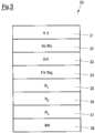
- Fig. 3 schematically shows a data tuple 30, which may be assigned or assignable to a feature of the represented environment (a tile when displayed as a gridmap). It is possible, but not necessary, for such a tuple to be explicitly assigned coordinate data 31 which specify the location in the represented environment in the required accuracy / resolution.
- a feature statement 32 which provides information on the presence of a feature. It can be 0/1 or the already mentioned presence probability of a feature (occupancy probability of a tile).
- 33 indicates the reliability probability as described, which is assigned to the respective features / tiles.
- Indicated at 34 is a flag indicating whether the reliability probability stored at 33 should be updated or not.
- 35 to 37 indicates various history data which are tile-specific as described above.
- the temporarily stored surveying histories can be stored. But they can also be stored in tiles, which is indicated by 38. Further storage can be made spatially resolved / tiled / feature-wise. As already said several times, the storage format can be similar to Fig. 3 shown to be implemented for each tile.
- Another part of the invention is a data carrier having data thereon representing computer-implementable code that, when executed, implements the described method for determining an electronically-usable representation.
- Fig. 4 a method for determining the position of a movable object 50 in an environment in which electronically detectable features are present described.
- features can again be understood as motion-relevant objects in the environment, in particular as obstacles to movement for the movable object.
- each feature corresponds to one or more tiles in the representation / view / storage as gridmap.
- the position determination may be done in a two-dimensional environment representation / map, such as for a vehicle traveling in an environment, or three-dimensional, such as for a working robot or flying equipment, e.g. B. a drone. Accordingly, the environmental representation is constructed two-dimensionally or three-dimensionally. As before, a two-dimensional example is described without wishing to exclude the application to three dimensions.
- the three-dimensional environment measurement does not only occur in a circle around the vehicle, but ultimately preferably in the hemisphere overarching the vehicle or the flying device or the robotic arm spanning the vehicle Sphere. Even then, characteristics according to direction (spatial direction) and distance are detected.
- a survey may then include the acquisition of multiple / many / all features in the selected area (half / sphere above / around the vehicle / robot). The spatial resolution is chosen according to the needs or technical abilities.
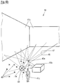
- Fig. 4a shows strongly schematized an environment 40.
- the circled cross symbolizes the vehicle 50.
- Around the vehicle 50 are distributed around electronically detectable, with squares symbolized features 41a, 41b, ..., 41z.
- Each considered feature (or tile considered) is assigned a presence probability V and a reliability Z.
- the presence probability tells how likely a feature / obstacle to travel is on the tile or not.
- the reliability indicates as to how reliably detectable the respective feature represented by the respective tile was assessed. Accordingly, the feature or tile 41a is assigned Va and Za, 41b are assigned Vb and Zb, and 41z are assigned Vz and Zz.
- the features of the tiles 41a to 41z can be detected with different reliability. They can be difficult to detect because they are, for example, small or filigree (support of the shelf 14) or because they are transparent / semitransparent (glass door 13). Other features such as walls can be very well detected.
- the features represented by the respective tiles 41a are therefore detectable with different reliability and have different values Za to Zz, as already described.
- the moving object In determining the position, the moving object measures its surroundings from its current perspective by recording 42 of the individual features / tiles 41.
- the survey result (the totality of the collected observations 42 of the detected features) is then evaluated. This evaluation addresses the reliability of capturing each feature. From the evaluation result, the position of the vehicle 50 in the map (represented environment) is determined.
- the reliabilities may be considered as weights of the individual detections 42. Thus, more reliable detectable features are more highly weighted in the result, while less reliable features are weighted lower in the result. In this way, a higher probability for the accuracy of the positioning result is given.
- the occupancy probability of the tiles / features affected by the individual acquisitions can also be included in the evaluation of the individual surveys when weighting the individual surveys 42. This can be used together with the reliability to weight the individual observations and then goes into the overall result.
- this, in particular the individual feature detections 42a-42z of the survey is compared with map data. A comparison of presumed results from a presumed position with the actually obtained survey results can be made, this comparison being able to take place in accordance with the individual acquisitions 42a-z and individually weighted according to the respective reliability and possibly also present probabilities.
- the evaluations of the individual detections 42 can then be combined mathematically, for example by product formation (or by summation in logarithmic terms), thus leading to an overall evaluation of a measurement.
- a particle filter algorithm can be used, which is also based on FIG. 4b is explained. It has the following steps: First, a suspected position of the moving object is determined. This can be done by "coupling" starting from a previously known position, ie updating the position in accordance with otherwise obtained information, such as odometry of the vehicle or other information such as preferably stereoscopic image processing. In this way, a suspected (hypothetical) position of the moving object is determined. In the two-dimensional it is a two-dimensional coordinate specification, in three-dimensional a three-dimensional coordinate specification. In Fig. 4b this corresponds to the position of the cross 50.
- a hypothetical measurement of the environment is digitally generated from their respective perspective. This is a theoretical / digital / electronic process in which, based on the map data and the hypothetical position, it is determined what a detection device 56 standing at the respective hypothetical location would have to "see” if it were there.
- a hypothetical survey is generated in this way, each of which in turn has many hypothetical detections of the features 41 surrounding the hypothetical position, each map having an indication of direction and distance.
- Fig. 4b schematically shows a somewhat more concrete situation of an environment 40.
- 50 symbolizes the vehicle, 41a to 41c symbolize different features.
- the wall 41a has found precipitation in the mapping and is represented with corresponding features of respective high presence probabilities (eg 0.99 or 1) on the corresponding tiles.
- the box symbolized by 41b (by way of example for parked goods, parked vehicle, etc.) is also mapped, in particular with a lesser probability of presence (for example 0.35).
- the person 41c will not be mapped with high probability. However, for the respective room tile from earlier sporadic observations, a certain occupancy probability / presence probability may have found their way into the map. This can then be low, for example. 0.07.
- the crosses 45 show the hypothetical positions (particles) addressed.
- the vehicle 50 itself is at a suspected position, as in FIG Fig. 4b located. It should be noted that this suspected position may have been updated from a previously determined position by odometry or the like. However, the former position can also be used as a (then inaccurate) assumed position.
- one of the many real detections of features from the perspective of the vehicle 50 in a survey is indicated.
- one of the many hypothetical detections of features is indicated from the perspective of the hypothetical position 45a, which has been highlighted for illustrative purposes. For the sake of clarity, these reference numerals are drawn only for the detection of a single feature (a wall location) from the perspective of the vehicle and only for one of the many particles 45.
- the detections 46 from the perspective of the vehicle 50 are actually done by corresponding devices 56 of the vehicle 50, while the detections 47 are hypothetical / theoretical and data processing based on the assumed position and map data.
- each hypothetical position 45 It is then determined for each hypothetical position 45 a probability wh for their correctness. This probability also depends on the reliability values of the features involved. In addition, their respective occupancy probabilities can be taken into account.
- the probability wh of a hypothetical position depends on the correctness probabilities we of the individual detections of the individual features from the respective hypothetical position.
- the correctness probabilities we of the individual detections 47 can also depend on the difference of the hypothetical detected distance at 47 to the actually recorded distance at 46. The dependency can be such that the greater the difference, the lower the relevance / weighting.
- a Gaussian distribution around the real measured distance can be assumed with a suitably chosen standard deviation ⁇ .
- the respective reliability value Zi of the detected feature i can flow.
- the value Zi at p1 can be multiplied by the weighting of the correctness probability, or it can be multiplied by the exponent at p2.
- the presence probability / occupancy probability V of the particular feature / tile under consideration can also be included.
- the individual probabilities we (i, 45a) can then be linked, for example multiplicatively.
- the normalizations take place in accordance with the stochastic calculation, that is, the values of we (i, 45a) ⁇ 1.
- the hypothetical survey from the hypothetical position 45a detects 100 features (ie, 1 ⁇ i ⁇ 100), then 100 associated values of we (i, 45a) are obtained. These can be multiplied over all i times or added in logarithmic.
- Reliability can also be incorporated at this point if it has not already been taken into consideration beforehand, for example by adding (multiplying, adding) to this overall product formation (or logarithmic summation). In this way, a probability wh (45a) of the correctness of a particular hypothetical position 45a is obtained.
- the actual position of the vehicle 50 can then be determined.
- One approach to doing so is to choose the position with the best / highest probability.
- Another possibility is to perform averaging of the respective positions in x and y (and optionally in z), weighted according to the respective probabilities wh, from a number of relatively good probabilities or from a given number of probabilities, and to assign these mean values as a new position to take.
- the reliability value of the features is taken into account when weighting individual measurement results. Reliable features went more weighted than less reliable, so the overall result is more likely to be closer to the right result.
- the described algorithm is also known as "Monte Carlo Localization". However, it is also possible to extend other localization methods by considering reliability values of the detected features. For example, a Kalman filter can be extended to include reliability values.
- the determined reliability values can also be used for path planning for a moving object in an environment.
- a digital representation of the environment is provided which represents a plurality of environmental features and for each of which at least some of these features also indicates reliability values or allows their derivation.
- These reliability values may be designed and determined as described above, and may be spatially resolved in addition to occupancy probabilities / presence probabilities.
- a waypoint is then set as the first point of a route to be planned. At the beginning of the procedure, the first point may be the current own position. In the further course, the first point may be a last selected point of the way.
- a second point following the first point and spaced therefrom is then determined by a pathfinding or routing algorithm that is not a specific subject of interest here.
- the second point can be checked for usability / passability using the digital representation including the specified reliability values.
Landscapes
- Engineering & Computer Science (AREA)
- Radar, Positioning & Navigation (AREA)
- Remote Sensing (AREA)
- Physics & Mathematics (AREA)
- General Physics & Mathematics (AREA)
- Automation & Control Theory (AREA)
- Electromagnetism (AREA)
- Computer Networks & Wireless Communication (AREA)
- Aviation & Aerospace Engineering (AREA)
- Databases & Information Systems (AREA)
- Optics & Photonics (AREA)
- Multimedia (AREA)
- Traffic Control Systems (AREA)
- Length Measuring Devices By Optical Means (AREA)
- Measurement Of The Respiration, Hearing Ability, Form, And Blood Characteristics Of Living Organisms (AREA)
Applications Claiming Priority (1)
| Application Number | Priority Date | Filing Date | Title |
|---|---|---|---|
| DE102018104780.0A DE102018104780A1 (de) | 2018-03-02 | 2018-03-02 | Verfahren zur Bestimmung einer elektronischen nützbaren Repräsentation einer Umgebung, Vorrichtung hierfür, Datenträger |
Publications (3)
| Publication Number | Publication Date |
|---|---|
| EP3534112A2 true EP3534112A2 (fr) | 2019-09-04 |
| EP3534112A3 EP3534112A3 (fr) | 2019-11-20 |
| EP3534112B1 EP3534112B1 (fr) | 2022-05-18 |
Family
ID=65724166
Family Applications (1)
| Application Number | Title | Priority Date | Filing Date |
|---|---|---|---|
| EP19160541.9A Active EP3534112B1 (fr) | 2018-03-02 | 2019-03-04 | Procédé de détermination d'une représentation utile électronique d'un environnement, dispositif correspondant, support de données |
Country Status (2)
| Country | Link |
|---|---|
| EP (1) | EP3534112B1 (fr) |
| DE (1) | DE102018104780A1 (fr) |
Families Citing this family (1)
| Publication number | Priority date | Publication date | Assignee | Title |
|---|---|---|---|---|
| DE102023204610A1 (de) * | 2023-05-17 | 2024-11-21 | Robert Bosch Gesellschaft mit beschränkter Haftung | Verfahren zur Auswertung von ortsaufgelösten Ist-Sensordaten |
Family Cites Families (7)
| Publication number | Priority date | Publication date | Assignee | Title |
|---|---|---|---|---|
| US20050234679A1 (en) * | 2004-02-13 | 2005-10-20 | Evolution Robotics, Inc. | Sequential selective integration of sensor data |
| US20080033645A1 (en) * | 2006-08-03 | 2008-02-07 | Jesse Sol Levinson | Pobabilistic methods for mapping and localization in arbitrary outdoor environments |
| DE102010028090A1 (de) * | 2010-04-22 | 2011-12-01 | Robert Bosch Gmbh | Navigationssystem und Navigationsverfahren für Fahrzeuge |
| CN103459099B (zh) * | 2011-01-28 | 2015-08-26 | 英塔茨科技公司 | 与一个可移动的远程机器人相互交流 |
| US8589012B2 (en) * | 2011-06-14 | 2013-11-19 | Crown Equipment Limited | Method and apparatus for facilitating map data processing for industrial vehicle navigation |
| US9996944B2 (en) * | 2016-07-06 | 2018-06-12 | Qualcomm Incorporated | Systems and methods for mapping an environment |
| CN110799804A (zh) * | 2017-06-30 | 2020-02-14 | 深圳市大疆创新科技有限公司 | 地图生成系统和方法 |
-
2018
- 2018-03-02 DE DE102018104780.0A patent/DE102018104780A1/de active Pending
-
2019
- 2019-03-04 EP EP19160541.9A patent/EP3534112B1/fr active Active
Also Published As
| Publication number | Publication date |
|---|---|
| DE102018104780A1 (de) | 2019-09-05 |
| EP3534112A3 (fr) | 2019-11-20 |
| EP3534112B1 (fr) | 2022-05-18 |
Similar Documents
| Publication | Publication Date | Title |
|---|---|---|
| EP3443301B1 (fr) | Procédé et système de détermination d'une position globale d'un premier repère | |
| EP2526378B1 (fr) | Procédé et système pour détecter la position d'un véhicule | |
| DE60118711T2 (de) | Entfernungsmessgerät zur kartierung eines zwei- oder dreidimensionalen volumens | |
| DE102015214338A1 (de) | Bestimmung einer Anordnungsinformation für ein Fahrzeug | |
| EP3017319A1 (fr) | Procédé permettant de déterminer la trajectoire d'objets physiques mobiles dans un espace, sur la base des données de détection de plusieurs capteurs | |
| DE102018218436A1 (de) | Fahrzeugparkassistenz | |
| EP3534297B1 (fr) | Procédé de détermination de la position d'un objet mobile, procédé de planification de trajet pou un objet mobile, dispositif correspondant, support de données | |
| EP4051982A1 (fr) | Procédé et dispositif de détection mobile pour détecter des éléments d'infrastructure d'un réseau de conduits souterrains | |
| DE102020206190A1 (de) | System und verfahren für die konfiguration einer arbeitsstätten warnzone. | |
| DE112020007655T5 (de) | Lokalisierungssystem und -verfahren für ein mobiles Gerät | |
| DE102014205640A1 (de) | Vermessung mittels mobilem Gerät | |
| EP4239428B1 (fr) | Procédé et système de navigation d'un chariot de manutention | |
| EP2749982B1 (fr) | Production de modèles de référence et actualisation | |
| EP3534112B1 (fr) | Procédé de détermination d'une représentation utile électronique d'un environnement, dispositif correspondant, support de données | |
| EP3764057B1 (fr) | Procédé de détermination de l'aptitude d'une position en tant que positionnement de mesure | |
| EP3711392B1 (fr) | Procédé et dispositif de détermination de position | |
| EP4386509B1 (fr) | Procédé d'autolocalisation dans un environnement de navigation et véhicule auto-localisé | |
| WO2012163632A1 (fr) | Procédé de détermination de position d'objets en mouvement | |
| EP2573583B1 (fr) | Procédé et appareil de recherche pour la recherche d'un appareil d'émission | |
| EP2963450B1 (fr) | Procédé et système de détermination de position destinés à la détermination de position d'un dispositif de communication mobile à l'aide d'un plan de mesure | |
| WO2013057192A1 (fr) | Procédé de mesure et de visualisation des conditions régnant dans l'espace interne d'un poste de fabrication | |
| WO2017144033A1 (fr) | Procédé de détermination et de visualisation de changements dans un environnement réel comportant un terrain réel et des objets réels se trouvant sur ce terrain | |
| DE102023125123B4 (de) | Verfahren zum Betreiben eines Flurförderzeugs in einem Lager und Flurförderzeug | |
| DE102017105758A1 (de) | Anordnung und verfahren zum analysieren der feldabdeckung eines drahtlosen lokalen netzes (wlan) in einem arbeitsbereich | |
| EP1486920A2 (fr) | Procédé de télédétection |
Legal Events
| Date | Code | Title | Description |
|---|---|---|---|
| PUAI | Public reference made under article 153(3) epc to a published international application that has entered the european phase |
Free format text: ORIGINAL CODE: 0009012 |
|
| STAA | Information on the status of an ep patent application or granted ep patent |
Free format text: STATUS: THE APPLICATION HAS BEEN PUBLISHED |
|
| AK | Designated contracting states |
Kind code of ref document: A2 Designated state(s): AL AT BE BG CH CY CZ DE DK EE ES FI FR GB GR HR HU IE IS IT LI LT LU LV MC MK MT NL NO PL PT RO RS SE SI SK SM TR |
|
| AX | Request for extension of the european patent |
Extension state: BA ME |
|
| PUAL | Search report despatched |
Free format text: ORIGINAL CODE: 0009013 |
|
| AK | Designated contracting states |
Kind code of ref document: A3 Designated state(s): AL AT BE BG CH CY CZ DE DK EE ES FI FR GB GR HR HU IE IS IT LI LT LU LV MC MK MT NL NO PL PT RO RS SE SI SK SM TR |
|
| AX | Request for extension of the european patent |
Extension state: BA ME |
|
| RIC1 | Information provided on ipc code assigned before grant |
Ipc: G01C 21/32 20060101ALI20191014BHEP Ipc: G01C 21/20 20060101AFI20191014BHEP Ipc: G01C 11/04 20060101ALI20191014BHEP Ipc: G01C 15/00 20060101ALI20191014BHEP Ipc: G05D 1/02 20060101ALI20191014BHEP Ipc: G01S 17/89 20060101ALI20191014BHEP |
|
| RAP1 | Party data changed (applicant data changed or rights of an application transferred) |
Owner name: SICK AG |
|
| STAA | Information on the status of an ep patent application or granted ep patent |
Free format text: STATUS: REQUEST FOR EXAMINATION WAS MADE |
|
| 17P | Request for examination filed |
Effective date: 20200520 |
|
| RBV | Designated contracting states (corrected) |
Designated state(s): AL AT BE BG CH CY CZ DE DK EE ES FI FR GB GR HR HU IE IS IT LI LT LU LV MC MK MT NL NO PL PT RO RS SE SI SK SM TR |
|
| STAA | Information on the status of an ep patent application or granted ep patent |
Free format text: STATUS: EXAMINATION IS IN PROGRESS |
|
| 17Q | First examination report despatched |
Effective date: 20200805 |
|
| GRAP | Despatch of communication of intention to grant a patent |
Free format text: ORIGINAL CODE: EPIDOSNIGR1 |
|
| STAA | Information on the status of an ep patent application or granted ep patent |
Free format text: STATUS: GRANT OF PATENT IS INTENDED |
|
| INTG | Intention to grant announced |
Effective date: 20211220 |
|
| GRAS | Grant fee paid |
Free format text: ORIGINAL CODE: EPIDOSNIGR3 |
|
| GRAA | (expected) grant |
Free format text: ORIGINAL CODE: 0009210 |
|
| STAA | Information on the status of an ep patent application or granted ep patent |
Free format text: STATUS: THE PATENT HAS BEEN GRANTED |
|
| AK | Designated contracting states |
Kind code of ref document: B1 Designated state(s): AL AT BE BG CH CY CZ DE DK EE ES FI FR GB GR HR HU IE IS IT LI LT LU LV MC MK MT NL NO PL PT RO RS SE SI SK SM TR |
|
| REG | Reference to a national code |
Ref country code: GB Ref legal event code: FG4D Free format text: NOT ENGLISH |
|
| REG | Reference to a national code |
Ref country code: CH Ref legal event code: EP |
|
| REG | Reference to a national code |
Ref country code: IE Ref legal event code: FG4D Free format text: LANGUAGE OF EP DOCUMENT: GERMAN |
|
| REG | Reference to a national code |
Ref country code: DE Ref legal event code: R096 Ref document number: 502019004389 Country of ref document: DE |
|
| REG | Reference to a national code |
Ref country code: AT Ref legal event code: REF Ref document number: 1493400 Country of ref document: AT Kind code of ref document: T Effective date: 20220615 |
|
| REG | Reference to a national code |
Ref country code: LT Ref legal event code: MG9D |
|
| REG | Reference to a national code |
Ref country code: NL Ref legal event code: MP Effective date: 20220518 |
|
| PG25 | Lapsed in a contracting state [announced via postgrant information from national office to epo] |
Ref country code: SE Free format text: LAPSE BECAUSE OF FAILURE TO SUBMIT A TRANSLATION OF THE DESCRIPTION OR TO PAY THE FEE WITHIN THE PRESCRIBED TIME-LIMIT Effective date: 20220518 Ref country code: PT Free format text: LAPSE BECAUSE OF FAILURE TO SUBMIT A TRANSLATION OF THE DESCRIPTION OR TO PAY THE FEE WITHIN THE PRESCRIBED TIME-LIMIT Effective date: 20220919 Ref country code: NO Free format text: LAPSE BECAUSE OF FAILURE TO SUBMIT A TRANSLATION OF THE DESCRIPTION OR TO PAY THE FEE WITHIN THE PRESCRIBED TIME-LIMIT Effective date: 20220818 Ref country code: NL Free format text: LAPSE BECAUSE OF FAILURE TO SUBMIT A TRANSLATION OF THE DESCRIPTION OR TO PAY THE FEE WITHIN THE PRESCRIBED TIME-LIMIT Effective date: 20220518 Ref country code: LT Free format text: LAPSE BECAUSE OF FAILURE TO SUBMIT A TRANSLATION OF THE DESCRIPTION OR TO PAY THE FEE WITHIN THE PRESCRIBED TIME-LIMIT Effective date: 20220518 Ref country code: HR Free format text: LAPSE BECAUSE OF FAILURE TO SUBMIT A TRANSLATION OF THE DESCRIPTION OR TO PAY THE FEE WITHIN THE PRESCRIBED TIME-LIMIT Effective date: 20220518 Ref country code: GR Free format text: LAPSE BECAUSE OF FAILURE TO SUBMIT A TRANSLATION OF THE DESCRIPTION OR TO PAY THE FEE WITHIN THE PRESCRIBED TIME-LIMIT Effective date: 20220819 Ref country code: FI Free format text: LAPSE BECAUSE OF FAILURE TO SUBMIT A TRANSLATION OF THE DESCRIPTION OR TO PAY THE FEE WITHIN THE PRESCRIBED TIME-LIMIT Effective date: 20220518 Ref country code: ES Free format text: LAPSE BECAUSE OF FAILURE TO SUBMIT A TRANSLATION OF THE DESCRIPTION OR TO PAY THE FEE WITHIN THE PRESCRIBED TIME-LIMIT Effective date: 20220518 Ref country code: BG Free format text: LAPSE BECAUSE OF FAILURE TO SUBMIT A TRANSLATION OF THE DESCRIPTION OR TO PAY THE FEE WITHIN THE PRESCRIBED TIME-LIMIT Effective date: 20220818 |
|
| PG25 | Lapsed in a contracting state [announced via postgrant information from national office to epo] |
Ref country code: RS Free format text: LAPSE BECAUSE OF FAILURE TO SUBMIT A TRANSLATION OF THE DESCRIPTION OR TO PAY THE FEE WITHIN THE PRESCRIBED TIME-LIMIT Effective date: 20220518 Ref country code: PL Free format text: LAPSE BECAUSE OF FAILURE TO SUBMIT A TRANSLATION OF THE DESCRIPTION OR TO PAY THE FEE WITHIN THE PRESCRIBED TIME-LIMIT Effective date: 20220518 Ref country code: LV Free format text: LAPSE BECAUSE OF FAILURE TO SUBMIT A TRANSLATION OF THE DESCRIPTION OR TO PAY THE FEE WITHIN THE PRESCRIBED TIME-LIMIT Effective date: 20220518 Ref country code: IS Free format text: LAPSE BECAUSE OF FAILURE TO SUBMIT A TRANSLATION OF THE DESCRIPTION OR TO PAY THE FEE WITHIN THE PRESCRIBED TIME-LIMIT Effective date: 20220918 |
|
| PG25 | Lapsed in a contracting state [announced via postgrant information from national office to epo] |
Ref country code: SM Free format text: LAPSE BECAUSE OF FAILURE TO SUBMIT A TRANSLATION OF THE DESCRIPTION OR TO PAY THE FEE WITHIN THE PRESCRIBED TIME-LIMIT Effective date: 20220518 Ref country code: SK Free format text: LAPSE BECAUSE OF FAILURE TO SUBMIT A TRANSLATION OF THE DESCRIPTION OR TO PAY THE FEE WITHIN THE PRESCRIBED TIME-LIMIT Effective date: 20220518 Ref country code: RO Free format text: LAPSE BECAUSE OF FAILURE TO SUBMIT A TRANSLATION OF THE DESCRIPTION OR TO PAY THE FEE WITHIN THE PRESCRIBED TIME-LIMIT Effective date: 20220518 Ref country code: EE Free format text: LAPSE BECAUSE OF FAILURE TO SUBMIT A TRANSLATION OF THE DESCRIPTION OR TO PAY THE FEE WITHIN THE PRESCRIBED TIME-LIMIT Effective date: 20220518 Ref country code: DK Free format text: LAPSE BECAUSE OF FAILURE TO SUBMIT A TRANSLATION OF THE DESCRIPTION OR TO PAY THE FEE WITHIN THE PRESCRIBED TIME-LIMIT Effective date: 20220518 Ref country code: CZ Free format text: LAPSE BECAUSE OF FAILURE TO SUBMIT A TRANSLATION OF THE DESCRIPTION OR TO PAY THE FEE WITHIN THE PRESCRIBED TIME-LIMIT Effective date: 20220518 |
|
| REG | Reference to a national code |
Ref country code: DE Ref legal event code: R097 Ref document number: 502019004389 Country of ref document: DE |
|
| PLBE | No opposition filed within time limit |
Free format text: ORIGINAL CODE: 0009261 |
|
| STAA | Information on the status of an ep patent application or granted ep patent |
Free format text: STATUS: NO OPPOSITION FILED WITHIN TIME LIMIT |
|
| PG25 | Lapsed in a contracting state [announced via postgrant information from national office to epo] |
Ref country code: AL Free format text: LAPSE BECAUSE OF FAILURE TO SUBMIT A TRANSLATION OF THE DESCRIPTION OR TO PAY THE FEE WITHIN THE PRESCRIBED TIME-LIMIT Effective date: 20220518 |
|
| 26N | No opposition filed |
Effective date: 20230221 |
|
| PG25 | Lapsed in a contracting state [announced via postgrant information from national office to epo] |
Ref country code: SI Free format text: LAPSE BECAUSE OF FAILURE TO SUBMIT A TRANSLATION OF THE DESCRIPTION OR TO PAY THE FEE WITHIN THE PRESCRIBED TIME-LIMIT Effective date: 20220518 |
|
| PG25 | Lapsed in a contracting state [announced via postgrant information from national office to epo] |
Ref country code: MC Free format text: LAPSE BECAUSE OF FAILURE TO SUBMIT A TRANSLATION OF THE DESCRIPTION OR TO PAY THE FEE WITHIN THE PRESCRIBED TIME-LIMIT Effective date: 20220518 |
|
| REG | Reference to a national code |
Ref country code: CH Ref legal event code: PL |
|
| REG | Reference to a national code |
Ref country code: BE Ref legal event code: MM Effective date: 20230331 |
|
| PG25 | Lapsed in a contracting state [announced via postgrant information from national office to epo] |
Ref country code: LU Free format text: LAPSE BECAUSE OF NON-PAYMENT OF DUE FEES Effective date: 20230304 |
|
| REG | Reference to a national code |
Ref country code: IE Ref legal event code: MM4A |
|
| PG25 | Lapsed in a contracting state [announced via postgrant information from national office to epo] |
Ref country code: LI Free format text: LAPSE BECAUSE OF NON-PAYMENT OF DUE FEES Effective date: 20230331 Ref country code: IT Free format text: LAPSE BECAUSE OF FAILURE TO SUBMIT A TRANSLATION OF THE DESCRIPTION OR TO PAY THE FEE WITHIN THE PRESCRIBED TIME-LIMIT Effective date: 20220518 Ref country code: IE Free format text: LAPSE BECAUSE OF NON-PAYMENT OF DUE FEES Effective date: 20230304 Ref country code: CH Free format text: LAPSE BECAUSE OF NON-PAYMENT OF DUE FEES Effective date: 20230331 |
|
| PG25 | Lapsed in a contracting state [announced via postgrant information from national office to epo] |
Ref country code: BE Free format text: LAPSE BECAUSE OF NON-PAYMENT OF DUE FEES Effective date: 20230331 |
|
| PG25 | Lapsed in a contracting state [announced via postgrant information from national office to epo] |
Ref country code: BG Free format text: LAPSE BECAUSE OF FAILURE TO SUBMIT A TRANSLATION OF THE DESCRIPTION OR TO PAY THE FEE WITHIN THE PRESCRIBED TIME-LIMIT Effective date: 20220518 |
|
| PG25 | Lapsed in a contracting state [announced via postgrant information from national office to epo] |
Ref country code: BG Free format text: LAPSE BECAUSE OF FAILURE TO SUBMIT A TRANSLATION OF THE DESCRIPTION OR TO PAY THE FEE WITHIN THE PRESCRIBED TIME-LIMIT Effective date: 20220518 |
|
| PGFP | Annual fee paid to national office [announced via postgrant information from national office to epo] |
Ref country code: AT Payment date: 20250319 Year of fee payment: 7 |
|
| PG25 | Lapsed in a contracting state [announced via postgrant information from national office to epo] |
Ref country code: CY Free format text: LAPSE BECAUSE OF FAILURE TO SUBMIT A TRANSLATION OF THE DESCRIPTION OR TO PAY THE FEE WITHIN THE PRESCRIBED TIME-LIMIT; INVALID AB INITIO Effective date: 20190304 |
|
| PG25 | Lapsed in a contracting state [announced via postgrant information from national office to epo] |
Ref country code: HU Free format text: LAPSE BECAUSE OF FAILURE TO SUBMIT A TRANSLATION OF THE DESCRIPTION OR TO PAY THE FEE WITHIN THE PRESCRIBED TIME-LIMIT; INVALID AB INITIO Effective date: 20190304 |
|
| PG25 | Lapsed in a contracting state [announced via postgrant information from national office to epo] |
Ref country code: TR Free format text: LAPSE BECAUSE OF FAILURE TO SUBMIT A TRANSLATION OF THE DESCRIPTION OR TO PAY THE FEE WITHIN THE PRESCRIBED TIME-LIMIT Effective date: 20220518 |
|
| PGFP | Annual fee paid to national office [announced via postgrant information from national office to epo] |
Ref country code: GB Payment date: 20260324 Year of fee payment: 8 |
|
| PGFP | Annual fee paid to national office [announced via postgrant information from national office to epo] |
Ref country code: DE Payment date: 20260320 Year of fee payment: 8 |
|
| PGFP | Annual fee paid to national office [announced via postgrant information from national office to epo] |
Ref country code: FR Payment date: 20260325 Year of fee payment: 8 |