EP3534236B1 - Appareil de conduction électrique - Google Patents
Appareil de conduction électrique Download PDFInfo
- Publication number
- EP3534236B1 EP3534236B1 EP18211105.4A EP18211105A EP3534236B1 EP 3534236 B1 EP3534236 B1 EP 3534236B1 EP 18211105 A EP18211105 A EP 18211105A EP 3534236 B1 EP3534236 B1 EP 3534236B1
- Authority
- EP
- European Patent Office
- Prior art keywords
- connector
- housing
- electric conduction
- conduction apparatus
- site
- Prior art date
- Legal status (The legal status is an assumption and is not a legal conclusion. Google has not performed a legal analysis and makes no representation as to the accuracy of the status listed.)
- Active
Links
Images


Classifications
-
- H—ELECTRICITY
- H01—ELECTRIC ELEMENTS
- H01R—ELECTRICALLY-CONDUCTIVE CONNECTIONS; STRUCTURAL ASSOCIATIONS OF A PLURALITY OF MUTUALLY-INSULATED ELECTRICAL CONNECTING ELEMENTS; COUPLING DEVICES; CURRENT COLLECTORS
- H01R33/00—Coupling devices specially adapted for supporting apparatus and having one part acting as a holder providing support and electrical connection via a counterpart which is structurally associated with the apparatus, e.g. lamp holders; Separate parts thereof
- H01R33/94—Holders formed as intermediate parts for linking a counter-part to a coupling part
-
- G—PHYSICS
- G06—COMPUTING OR CALCULATING; COUNTING
- G06F—ELECTRIC DIGITAL DATA PROCESSING
- G06F1/00—Details not covered by groups G06F3/00 - G06F13/00 and G06F21/00
- G06F1/16—Constructional details or arrangements
- G06F1/1613—Constructional details or arrangements for portable computers
- G06F1/1632—External expansion units, e.g. docking stations
-
- H—ELECTRICITY
- H01—ELECTRIC ELEMENTS
- H01R—ELECTRICALLY-CONDUCTIVE CONNECTIONS; STRUCTURAL ASSOCIATIONS OF A PLURALITY OF MUTUALLY-INSULATED ELECTRICAL CONNECTING ELEMENTS; COUPLING DEVICES; CURRENT COLLECTORS
- H01R13/00—Details of coupling devices of the kinds covered by groups H01R12/70 or H01R24/00 - H01R33/00
- H01R13/46—Bases; Cases
- H01R13/516—Means for holding or embracing insulating body, e.g. casing, hoods
-
- H—ELECTRICITY
- H02—GENERATION; CONVERSION OR DISTRIBUTION OF ELECTRIC POWER
- H02J—ELECTRIC POWER NETWORKS; CIRCUIT ARRANGEMENTS OR SYSTEMS FOR SUPPLYING OR DISTRIBUTING ELECTRIC POWER; SYSTEMS FOR STORING ELECTRIC ENERGY
- H02J7/00—Circuit arrangements for charging or discharging batteries or for supplying loads from batteries
- H02J7/70—Circuit arrangements for charging or discharging batteries or for supplying loads from batteries characterised by the mechanical construction
- H02J7/731—Circuit arrangements for charging or discharging batteries or for supplying loads from batteries characterised by the mechanical construction specially adapted for holding portable devices containing batteries
-
- H—ELECTRICITY
- H02—GENERATION; CONVERSION OR DISTRIBUTION OF ELECTRIC POWER
- H02J—ELECTRIC POWER NETWORKS; CIRCUIT ARRANGEMENTS OR SYSTEMS FOR SUPPLYING OR DISTRIBUTING ELECTRIC POWER; SYSTEMS FOR STORING ELECTRIC ENERGY
- H02J7/00—Circuit arrangements for charging or discharging batteries or for supplying loads from batteries
- H02J7/70—Circuit arrangements for charging or discharging batteries or for supplying loads from batteries characterised by the mechanical construction
- H02J7/751—Circuit arrangements for charging or discharging batteries or for supplying loads from batteries characterised by the mechanical construction concerning the insertion or the connection of the batteries
-
- H—ELECTRICITY
- H04—ELECTRIC COMMUNICATION TECHNIQUE
- H04B—TRANSMISSION
- H04B1/00—Details of transmission systems, not covered by a single one of groups H04B3/00 - H04B13/00; Details of transmission systems not characterised by the medium used for transmission
- H04B1/38—Transceivers, i.e. devices in which transmitter and receiver form a structural unit and in which at least one part is used for functions of transmitting and receiving
- H04B1/3827—Portable transceivers
- H04B1/3877—Arrangements for enabling portable transceivers to be used in a fixed position, e.g. cradles or boosters
-
- H—ELECTRICITY
- H04—ELECTRIC COMMUNICATION TECHNIQUE
- H04B—TRANSMISSION
- H04B1/00—Details of transmission systems, not covered by a single one of groups H04B3/00 - H04B13/00; Details of transmission systems not characterised by the medium used for transmission
- H04B1/38—Transceivers, i.e. devices in which transmitter and receiver form a structural unit and in which at least one part is used for functions of transmitting and receiving
- H04B1/3827—Portable transceivers
- H04B1/3888—Arrangements for carrying or protecting transceivers
-
- H—ELECTRICITY
- H04—ELECTRIC COMMUNICATION TECHNIQUE
- H04M—TELEPHONIC COMMUNICATION
- H04M1/00—Substation equipment, e.g. for use by subscribers
- H04M1/02—Constructional features of telephone sets
- H04M1/04—Supports for telephone transmitters or receivers
Definitions
- the present invention relates to an electric conduction apparatus that supports an electronic device having a predetermined surface provided with a connector insertion port and is capable of being electrically connected to this electronic device.
- a portable game system is configured to be supported by an electric conduction apparatus called a cradle such as that disclosed in JP 2017-85743A , for example.
- This cradle has a connector protruding upward, and power is supplied by inserting this connector into a connector insertion portion formed in a lower surface of the game system.
- JP 2017-85743A is an example of related art.
- US 2013/016563 discloses a connector apparatus including a holder that holds an electronic apparatus having a female connector, and a male connector to be inserted into the female connector to connect thereto when the electronic apparatus is held by the holder.
- US 2008/037767 discloses a stand for a handset having a display.
- the stand consists of a fixed portion and an adjustable portion coupled to the fixed portion.
- the adjustable portion is operable to receive the handset and operable for adjustment of a viewing angle of the handset.
- US 2013/241470 A1 discloses a universal dock having a universal cradle for cradling a portable terminal having various sizes and types or accessory thereon, and a connector dummy receiving a connector for electrically connecting to the portable terminal and moving upward and downward on the universal cradle.
- US 2017/117729 A1 discloses a pedestal type device that functions as anon-limiting example charger comprises a connection portion that is constituted by a connection plug and a cover.
- the game apparatus in order to detach the game system from the electric conduction apparatus in a state where the connector is inserted into the connector insertion port, the game apparatus may be pulled up in parallel to the direction in which the connector is inserted.
- the game system can be detached from the electric conduction apparatus by being tilted forward, for example, there is also a possibility that an unnecessary load will be applied to the connector.
- the connector is supported to be pivotable about the first axis line located on the rear side relative to the connector.
- the facing surface may be configured to be pivotable together with the connector by the pivoting mechanism.
- substantially parallel may not be “completely parallel”, and need only be “parallel to an extent that the connector can be smoothly inserted into the connector insertion port”.
- the pivoting mechanism may have various configurations.
- the pivoting mechanism may be configured to include a guide portion at least a portion of which can be inserted into the recessed portion, the guide portion having the facing surface.
- the pivoting mechanism may have a guide portion at least a portion of which can be inserted into the recessed portion, the guide portion protruding from the facing surface to the front side.
- the pivoting mechanism may include an elastic member configured to bias the connector in a direction in which the connector is inserted into the connector insertion port.
- the connector is always pressed in the direction in which the connector is inserted, and thus the connector can be biased to the position at which the connector can be easily inserted into the connector insertion port.
- the electronic device may have a front surface extending from a front end of the predetermined surface
- the housing may have a support surface that faces the predetermined surface of the electronic device
- the support surface may be configured such that a portion at which the predetermined surface and the front surface of the electronic device intersect with each other can come into contact with the support surface when the connector inserted into the connector insertion port is detached from the connector insertion port.
- the intersecting portion of the electronic device comes into contact with the support surface of the housing, and thus this contact portion serves as the fulcrum and the electronic device can be stably pivoted forward.
- the connector also smoothly pivots along with this stable pivoting, and thus it is possible to easily separate the connector from the connector insertion port.
- the housing may have a base portion having a surface that faces the predetermined surface of the electronic device and an extension portion having a front surface that extends from the surface of the base portion, the base portion and the extension portion may be configured to intersect with each other in a side view, and the connector may be disposed on the housing side relative to a virtual plane that connects a front end of the surface of the base portion and an upper end of the front surface.
- the base portion and the extension portion may be configured to have an L-shape in a side view, for example.
- the housing may have a base portion having a surface that faces the predetermined surface of the electronic device and an extension portion that has a front surface extending from the surface of the base portion and a back surface that is opposite to the front surface, and the electric conduction apparatus may further include a stand member that is attached to a back surface of the extension portion, and a linking mechanism configured to link the stand member to the housing so as to be capable of pivoting about a second axis line, the linking mechanism being capable of adjusting an angle between the stand member and the housing.
- the linking mechanism may be configured to detachably link the stand member and the housing together, and separate the stand member from the housing when the angle between the stand member and the housing is a predetermined angle or more.
- the stand member when the angle of the stand member with respect to the housing is forcibly increased, for example, if the angle is the predetermined angle or more, the stand member separates from the housing, and thus it is possible to reduce the possibility that the stand member and the housing will be damaged.
- the stand member may be configured such that a site of the housing that is located above the second axis line comes into contact with the housing when the angle between the stand member and the housing is the predetermined angle.
- the linking mechanism may include a linking portion provided in the housing and a pair of fixing portions that are provided in the stand member and detachably fixed to the linking portion so as to sandwich two ends of the linking portion in a direction along the second axis line.
- the linking mechanism may further include an engagement portion that is provided between the pair of fixing portions of the stand member and can engage with the linking portion.
- an inclined portion may be formed in at least one of portions at which the fixing portions and the linking portion are in contact with each other in a state where the fixing portions and the linking portion are fixed to each other, and the fixing portions and the linking portion may be configured to be fixed after sliding over the inclined surface.
- the linking mechanism may include a first site that is provided in the extension portion, a second site that has the linking portion, and a hinge portion that links the first site and the second site and enables the first site and the second site to pivot relative to each other about the second axis line.
- this configuration is one example of the linking mechanism, by using, as a hinge portion, a member that requires torque for pivoting of a torque hinge or the like, the force required for pivoting can be increased by the torque portion when the stand member is pivoted, for example.
- the angle of the stand member with respect to the housing can be adjusted steplessly, and the angle at which the housing is installed can be finely adjusted.
- a material for forming the first site and the second site may have a rigidity that is higher than that of a material for forming the housing.
- the first and second sites may be made of a resin material containing glass fibers, and in this case, at least a portion of the first and second sites may be accommodated in the housing.
- the resin material including glass fibers has high strength, but it is difficult to color the resin material to a desired color in some cases. Thus, there is a possibility that the aesthetic appearance of the first and second sites cannot be increased, and thus by housing at least portions of these sites in the housing, it will be difficult to see these sites from the outside.
- the electric conduction apparatus may be configured such that the electronic device can be charged when the connector is inserted into the connector insertion port of the electronic device.
- the electric conduction apparatus it is possible to reduce the possibility that an unnecessary load will be applied to the connector.
- An example of a game system 1 according to the exemplary embodiment includes a main body apparatus (an information processing apparatus; which functions as a game apparatus main body in the exemplary embodiment) 2, a left controller 3, and a right controller 4.
- a main body apparatus an information processing apparatus; which functions as a game apparatus main body in the exemplary embodiment
- a left controller 3 and a right controller 4 are attachable to and detachable from the main body apparatus 2. That is, the game system 1 can be used as a unified apparatus obtained by attaching each of the left controller 3 and the right controller 4 to the main body apparatus 2.
- the main body apparatus 2, the left controller 3, and the right controller 4 can also be used as separate bodies (see FIG. 2 ) .
- the hardware configuration of the game system 1 according to the exemplary embodiment is described, and then, the control of the game system 1 according to the exemplary embodiment is described.
- FIG. 1 is a diagram showing an example of the state where the left controller 3 and the right controller 4 are attached to the main body apparatus 2. As shown in FIG. 1 , each of the left controller 3 and the right controller 4 is attached to and unified with the main body apparatus 2.
- the main body apparatus 2 is an apparatus for performing various processes (e.g., game processing) in the game system 1.
- the main body apparatus 2 includes a display 12.
- Each of the left controller 3 and the right controller 4 is an apparatus including operation sections with which a user provides inputs.
- FIG. 2 is a diagram showing an example of the state where each of the left controller 3 and the right controller 4 is detached from the main body apparatus 2. As shown in FIGS. 1 and 2 , the left controller 3 and the right controller 4 are attachable to and detachable from the main body apparatus 2. It should be noted that hereinafter, the left controller 3 and the right controller 4 will occasionally be referred to collectively as a "controller”.
- FIG. 3 is six orthogonal views showing an example of the main body apparatus 2.
- the main body apparatus 2 includes an approximately plate-shaped housing 11.
- a main surface in other words, a surface on a front side, i.e., a surface on which the display 12 is provided
- the housing 11 has a generally rectangular shape.
- the shape and the size of the housing 11 are optional.
- the housing 11 may be of a portable size.
- the main body apparatus 2 alone or the unified apparatus obtained by attaching the left controller 3 and the right controller 4 to the main body apparatus 2 may function as a mobile apparatus.
- the main body apparatus 2 or the unified apparatus may function as a handheld apparatus or a portable apparatus.
- the main body apparatus 2 includes the display 12, which is provided on the main surface of the housing 11.
- the display 12 displays an image generated by the main body apparatus 2.
- the display 12 is a liquid crystal display device (LCD).
- the main body apparatus 2 includes a touch panel 13 on a screen of the display 12.
- the touch panel 13 is of a type that allows a multi-touch input (e.g., a capacitive type) .
- the touch panel 13, however, may be of any type, and for example, the touch panel 13 may be of a type that allows a single-touch input (e.g., a resistive type).
- the main body apparatus 2 includes speakers (i.e., speakers 88 shown in FIG. 6 ) within the housing 11. As shown in FIG. 3 , speaker holes 11a and 11b are formed on the main surface of the housing 11. Then, sounds output from the speakers 88 are output through the speaker holes 11a and 11b.
- speakers i.e., speakers 88 shown in FIG. 6
- the main body apparatus 2 includes a left terminal 17, which is a terminal for the main body apparatus 2 to perform wired communication with the left controller 3, and a right terminal 21, which is a terminal for the main body apparatus 2 to perform wired communication with the right controller 4.
- the main body apparatus 2 includes a slot 23.
- the slot 23 is provided on an upper side surface of the housing 11.
- the slot 23 is so shaped as to allow a predetermined type of storage medium to be attached to the slot 23.
- the predetermined type of storage medium is, for example, a dedicated storage medium (e.g., a dedicated memory card) for the game system 1 and an information processing apparatus of the same type as the game system 1.
- the predetermined type of storage medium is used to store, for example, data (e.g., saved data of an application or the like) used by the main body apparatus 2 and/or a program (e.g., a program for an application or the like) executed by the main body apparatus 2.
- the main body apparatus 2 includes a power button 28.
- a lower surface (predetermined surface) of the main body apparatus 2 includes a lower terminal 27.
- the lower terminal 27 is a terminal for the main body apparatus 2 to communicate with a cradle and the charging device, which will be described later, to perform charging.
- the lower terminal 27 is a USB connector (more specifically, a female connector), and a male connector of a charging device 1000, which will be described later, is inserted into this female connector (connector insertion port) 27.
- the game system 1 can display on a stationary monitor an image generated by and output from the main body apparatus 2.
- the cradle has the function of charging the unified apparatus or the main body apparatus 2 alone mounted on the cradle.
- the cradle has the function of a hub device (specifically, a USB hub).
- the center of the main body apparatus 2 in the left-right direction is provided with a groove (recessed portion) 29 that has a rectangular shape in a front view and extends upward from the portion at which the lower surface and the back surface are linked.
- This recessed portion 29 is formed to have a rectangular cross-section by a bottom surface 291 and side wall surfaces 292 on both the right and left sides of the bottom surface 291.
- this groove 29 is formed at a position corresponding with the female connector 27 in the left-right direction, and is formed rearward of the female connector 27.
- the female connector 27 and the bottom surface 291 of the groove 29 are located apart from each other by a predetermined distance.
- FIG. 4 is six orthogonal views showing an example of the left controller 3.
- the left controller 3 includes a housing 31.
- the housing 31 has a vertically long shape, i.e., is shaped to be long in an up-down direction (i.e., a y-axis direction shown in FIGS. 1 and 4 ) .
- the left controller 3 can also be held in the orientation in which the left controller 3 is vertically long.
- the housing 31 has such a shape and a size that when held in the orientation in which the housing 31 is vertically long, the housing 31 can be held with one hand, particularly the left hand.
- the left controller 3 can also be held in the orientation in which the left controller 3 is horizontally long. When held in the orientation in which the left controller 3 is horizontally long, the left controller 3 may be held with both hands.
- the left controller 3 includes an analog stick 32. As shown in FIG. 4 , the analog stick 32 is provided on a main surface of the housing 31. The analog stick 32 can be used as a direction input section with which a direction can be input. The user tilts the analog stick 32 and thereby can input a direction corresponding to the direction of the tilt (and input a magnitude corresponding to the angle of the tilt) . It should be noted that the left controller 3 may include a directional pad, a slide stick that allows a slide input, or the like as the direction input section, instead of the analog stick. Further, in the exemplary embodiment, it is possible to provide an input by pressing the analog stick 32.
- the left controller 3 includes various operation buttons.
- the left controller 3 includes four operation buttons 33 to 36 (specifically, a right direction button 33, a down direction button 34, an up direction button 35, and a left direction button 36) on the main surface of the housing 31.
- the left controller 3 includes a record button 37 and a "-" (minus) button 47.
- the left controller 3 includes a first L-button 38 and a ZL-button 39 in an upper left portion of a side surface of the housing 31.
- the left controller 3 includes a second L-button 43 and a second R-button 44, on the side surface of the housing 31 on which the left controller 3 is attached to the main body apparatus 2.
- These operation buttons are used to give instructions depending on various programs (e.g., an OS program and an application program) executed by the main body apparatus 2.
- the left controller 3 includes a terminal 42 for the left controller 3 to perform wired communication with the main body apparatus 2.
- FIG. 5 is six orthogonal views showing an example of the right controller 4.
- the right controller 4 includes a housing 51.
- the housing 51 has a vertically long shape, i.e., is shaped to be long in the up-down direction.
- the right controller 4 can also be held in the orientation in which the right controller 4 is vertically long.
- the housing 51 has such a shape and a size that when held in the orientation in which the housing 51 is vertically long, the housing 51 can be held with one hand, particularly the right hand. Further, the right controller 4 can also be held in the orientation in which the right controller 4 is horizontally long.
- the outer surface of the housing 51 of the right controller 4 is defined as follows. That is, the housing 51 is formed in an approximate rectangular parallelepiped shape, and includes a rectangular first main surface whose longitudinal direction is the up-down direction, and a second main surface that is opposite to the first main surface. Further, in the housing 51, the upper end surface in the longitudinal direction of these main surfaces constitutes a first end surface, and the lower end surface constitutes a second end surface. Also, a right side surface in the transverse direction of both main surfaces constitutes a first side end surface, and a left side surface constitutes a second side end surface.
- a left end portion of the first end surface has a flat surface oriented upward in the longitudinal direction, and the first end surface is configured to be curved downward to the right side, and is linked to the upper end of the first side end surface.
- a curved first R-button 60 is disposed on this first end surface.
- a left end portion of the second end surface has a flat surface oriented downward in the longitudinal direction, and the second end surface is configured to be curved upward to the right side, and is linked to the lower end of the first side end surface.
- An infrared image capturing section 123 and an infrared light-emitting section 124 which will be described later, are disposed on this second end surface.
- the operation buttons 53 to 58 and the analog stick 32 that are provided on the first main surface of the right controller 4 are examples of the first operation section of the present invention.
- the right controller 4 includes a curved first R-button 60 on a first end surface of the housing 51 and a ZR-button 61 that protrudes toward the back surface and can be pushed from above on the back surface side of the first R-button 60.
- a raised portion 500 is formed below this ZR button 61. This raised portion 500 is a site protruding from the second main surface, and has an inclined surface that extends toward the second main surface downward from the ZR-button 61.
- the right controller 4 includes an infrared image capturing section 123 and an infrared light-emitting section 124, which are placed within the housing 51.
- the infrared image capturing section 123 captures a portion around the right controller 4 through the window portion 68 such that a down direction of the right controller 4 (a negative y-axis direction shown in FIG. 5 ) is the image capturing direction.
- the infrared light-emitting section 124 emits infrared light through the window portion 68 to an image capturing target to be captured by the infrared image capturing section 123 such that a predetermined range about the down direction of the right controller 4 (the negative y-axis direction shown in FIG. 5 ) is the emission range.
- the window portion 68 is used to protect a lens of a camera of the infrared image capturing section 123, a light emitter of the infrared light-emitting section 124, and the like and composed of a material (e.g., a transparent material) that transmits light of a wavelength sensed by the camera and light emitted from the light emitter.
- the right controller 4 includes an NFC communication section 122.
- the NFC communication section 122 performs short-range wireless communication based on the NFC (Near Field Communication) standard.
- the NFC communication section 122 includes an antenna 122a, which is used for short-range wireless communication, and a circuit (e.g., an NFC chip) for generating a signal (a radio wave) to be sent from the antenna 122a.
- a circuit e.g., an NFC chip
- the NFC communication section 122 may perform short-range wireless communication through any proximity communication (or contactless communication), instead of performing short-range wireless communication based on the NFC standard.
- the NFC standard can be used for proximity communication (contactless communication), and "may perform short-range wireless communication through any proximity communication (or contactless communication)" is intended to mean that short-range wireless communication may be performed through other proximity communication except for proximity communication based on the NFC standard.
- the main body apparatus 2 includes a processor 81.
- the processor 81 is an information processing section for executing various types of information processing to be executed by the main body apparatus 2.
- the processor 81 may be composed only of a CPU (Central Processing Unit), or may be composed of a SoC (System-on-a-chip) having a plurality of functions such as a CPU function and a GPU (Graphics Processing Unit) function.
- the processor 81 executes an information processing program (e.g., a game program) stored in a storage section (specifically, an internal storage medium such as a flash memory 84, an external storage medium attached to the slot 23, or the like), thereby performing the various types of information processing.
- a storage section specifically, an internal storage medium such as a flash memory 84, an external storage medium attached to the slot 23, or the like
- the main body apparatus 2 includes a flash memory 84 and a DRAM (Dynamic Random Access Memory) 85 as examples of internal storage media built into the main body apparatus 2.
- the flash memory 84 and the DRAM 85 are connected to the processor 81.
- the flash memory 84 is a memory mainly used to store various data (or programs) to be saved in the main body apparatus 2.
- the DRAM 85 is a memory used to temporarily store various data used for information processing.
- the main body apparatus 2 includes a slot interface (hereinafter abbreviated as "I/F") 91.
- the slot I/F 91 is connected to the processor 81.
- the slot I/F 91 is connected to the slot 23, and in accordance with an instruction from the processor 81, reads and writes data from and to the predetermined type of storage medium (e.g., a dedicated memory card) attached to the slot 23.
- the predetermined type of storage medium e.g., a dedicated memory card
- the processor 81 appropriately reads and writes data from and to the flash memory 84, the DRAM 85, and each of the above storage media, thereby performing the above information processing.
- the main body apparatus 2 includes a network communication section 82.
- the network communication section 82 is connected to the processor 81.
- the network communication section 82 communicates (specifically, through wireless communication) with an external apparatus via a network.
- the network communication section 82 connects to a wireless LAN and communicates with an external apparatus, using a method compliant with the Wi-Fi standard.
- the network communication section 82 wirelessly communicates with another main body apparatus 2 of the same type, using a predetermined communication method (e.g., communication based on a unique protocol or infrared light communication).
- the wireless communication in the above second communication form achieves the function of enabling so-called "local communication" in which the main body apparatus 2 can wirelessly communicate with another main body apparatus 2 placed in a closed local network area, and the plurality of main body apparatuses 2 directly communicate with each other to transmit and receive data.
- the main body apparatus 2 includes a controller communication section 83.
- the controller communication section 83 is connected to the processor 81.
- the controller communication section 83 wirelessly communicates with the left controller 3 and/or the right controller 4.
- the communication method between the main body apparatus 2 and the left controller 3 and the right controller 4 is optional.
- the controller communication section 83 performs communication compliant with the Bluetooth (registered trademark) standard with the left controller 3 and with the right controller 4.
- the processor 81 is connected to the left terminal 17, the right terminal 21, and the lower terminal 27.
- the processor 81 transmits data to the left controller 3 via the left terminal 17 and also receives operation data from the left controller 3 via the left terminal 17.
- the processor 81 transmits data to the right controller 4 via the right terminal 21 and also receives operation data from the right controller 4 via the right terminal 21.
- the processor 81 transmits data to the cradle via the lower terminal 27.
- the main body apparatus 2 can perform both wired communication and wireless communication with each of the left controller 3 and the right controller 4.
- the main body apparatus 2 includes a touch panel controller 86, which is a circuit for controlling the touch panel 13.
- the touch panel controller 86 is connected between the touch panel 13 and the processor 81. Based on a signal from the touch panel 13, the touch panel controller 86 generates, for example, data indicating the position where a touch input is provided. Then, the touch panel controller 86 outputs the data to the processor 81.
- the display 12 is connected to the processor 81.
- the processor 81 displays a generated image (e.g., an image generated by executing the above information processing) and/or an externally acquired image on the display 12.
- the main body apparatus 2 includes a codec circuit 87 and speakers (specifically, a left speaker and a right speaker) 88.
- the codec circuit 87 is connected to the speakers 88 and a sound input/output terminal 25 and also connected to the processor 81.
- the codec circuit 87 is a circuit for controlling the input and output of sound data to and from the speakers 88 and the sound input/output terminal 25.
- the main body apparatus 2 includes an acceleration sensor 89.
- the acceleration sensor 89 detects the magnitudes of accelerations along predetermined three axial (e.g., xyz axes shown in FIG. 1 ) directions . It should be noted that the acceleration sensor 89 may detect an acceleration along one axial direction or accelerations along two axial directions.
- the main body apparatus 2 includes an angular velocity sensor 90.
- the angular velocity sensor 90 detects angular velocities about predetermined three axes (e.g., the xyz axes shown in FIG. 1 ) . It should be noted that the angular velocity sensor 90 may detect an angular velocity about one axis or angular velocities about two axes.
- the acceleration sensor 89 and the angular velocity sensor 90 are connected to the processor 81, and the detection results of the acceleration sensor 89 and the angular velocity sensor 90 are output to the processor 81. Based on the detection results of the acceleration sensor 89 and the angular velocity sensor 90, the processor 81 can calculate information regarding the motion and/or the orientation of the main body apparatus 2.
- the main body apparatus 2 includes a power control section 97 and a battery 98.
- the power control section 97 is connected to the battery 98 and the processor 81. Further, although not shown in FIG. 6 , the power control section 97 is connected to components of the main body apparatus 2 (specifically, components that receive power supplied from the battery 98, the left terminal 17, and the right terminal 21). Based on a command from the processor 81, the power control section 97 controls the supply of power from the battery 98 to the above components.
- the battery 98 is connected to the lower terminal 27.
- an external charging device e.g., the cradle
- the battery 98 is charged with the supplied power.
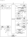
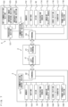
- FIG. 7 is a block diagram showing examples of the internal configurations of the main body apparatus 2, the left controller 3, and the right controller 4. It should be noted that the details of the internal configuration of the main body apparatus 2 are shown in FIG. 6 and therefore are omitted in FIG. 7 .
- the left controller 3 includes a communication control section 101, which communicates with the main body apparatus 2. As shown in FIG. 7 , the communication control section 101 is connected to components including the terminal 42. In the exemplary embodiment, the communication control section 101 can communicate with the main body apparatus 2 through both wired communication via the terminal 42 and wireless communication not via the terminal 42.
- the communication control section 101 controls the method for communication performed by the left controller 3 with the main body apparatus 2. That is, when the left controller 3 is attached to the main body apparatus 2, the communication control section 101 communicates with the main body apparatus 2 via the terminal 42. Further, when the left controller 3 is detached from the main body apparatus 2, the communication control section 101 wirelessly communicates with the main body apparatus 2 (specifically, the controller communication section 83).
- the wireless communication between the communication control section 101 and the controller communication section 83 is performed in accordance with the Bluetooth (registered trademark) standard, for example.
- the left controller 3 includes a memory 102 such as a flash memory.
- the communication control section 101 includes, for example, a microcomputer (or a microprocessor) and executes firmware stored in the memory 102, thereby performing various processes.
- the left controller 3 includes buttons 103 (specifically, the buttons 33 to 39, 43, 44, and 47) . Further, the left controller 3 includes the analog stick ("stick" in FIG. 7 ) 32. Each of the buttons 103 and the analog stick 32 outputs information regarding an operation performed on itself to the communication control section 101 repeatedly at appropriate timing.
- the left controller 3 includes inertial sensors. Specifically, the left controller 3 includes an acceleration sensor 104. Further, the left controller 3 includes an angular velocity sensor 105. In the exemplary embodiment, the acceleration sensor 104 detects the magnitudes of accelerations along predetermined three axial (e.g., xyz axes shown in FIG. 4 ) directions . It should be noted that the acceleration sensor 104 may detect an acceleration along one axial direction or accelerations along two axial directions. In the exemplary embodiment, the angular velocity sensor 105 detects angular velocities about predetermined three axes (e.g., the xyz axes shown in FIG. 4 ) .
- the angular velocity sensor 105 may detect an angular velocity about one axis or angular velocities about two axes.
- Each of the acceleration sensor 104 and the angular velocity sensor 105 is connected to the communication control section 101. Then, the detection results of the acceleration sensor 104 and the angular velocity sensor 105 are output to the communication control section 101 repeatedly at appropriate timing.
- the communication control section 101 acquires information regarding an input (specifically, information regarding an operation or the detection result of the sensor) from each of input sections (specifically, the buttons 103, the analog stick 32, and the sensors 104 and 105).
- the communication control section 101 transmits operation data including the acquired information (or information obtained by performing predetermined processing on the acquired information) to the main body apparatus 2. It should be noted that the operation data is transmitted repeatedly, once every predetermined time. It should be noted that the interval at which the information regarding an input is transmitted from each of the input sections to the main body apparatus 2 may or may not be the same.
- the left controller 3 includes a vibrator 107 for giving notification to the user by a vibration.
- the vibrator 107 is controlled by a command from the main body apparatus 2. That is, if receiving the above command from the main body apparatus 2, the communication control section 101 drives the vibrator 107 in accordance with the received command.
- the left controller 3 includes a codec section 106. If receiving the above command, the communication control section 101 outputs a control signal corresponding to the command to the codec section 106.
- the codec section 106 generates a driving signal for driving the vibrator 107 from the control signal from the communication control section 101 and outputs the driving signal to the vibrator 107. Consequently, the vibrator 107 operates.
- the vibrator 107 is a linear vibration motor. Unlike a regular motor that rotationally moves, the linear vibration motor is driven in a predetermined direction in accordance with an input voltage and therefore can be vibrated at an amplitude and a frequency corresponding to the waveform of the input voltage.
- a vibration control signal transmitted from the main body apparatus 2 to the left controller 3 may be a digital signal representing the frequency and the amplitude every unit of time .
- the main body apparatus 2 may transmit information indicating the waveform itself. The transmission of only the amplitude and the frequency, however, enables a reduction in the amount of communication data.
- the codec section 106 converts a digital signal indicating the values of the amplitude and the frequency acquired from the communication control section 101 into the waveform of an analog voltage and inputs a voltage in accordance with the resulting waveform, thereby driving the vibrator 107.
- the main body apparatus 2 changes the amplitude and the frequency to be transmitted every unit of time and thereby can control the amplitude and the frequency at which the vibrator 107 is to be vibrated at that time.
- the codec section 106 combines waveforms indicated by the plurality of received amplitudes and frequencies and thereby can generate the waveform of a voltage for controlling the vibrator 107.
- the left controller 3 includes a power supply section 108.
- the power supply section 108 includes a battery and a power control circuit.
- the power control circuit is connected to the battery and also connected to components of the left controller 3 (specifically, components that receive power supplied from the battery).
- the right controller 4 includes a communication control section 111, which communicates with the main body apparatus 2. Further, the right controller 4 includes a memory 112, which is connected to the communication control section 111.
- the communication control section 111 is connected to components including the terminal 64.
- the communication control section 111 and the memory 112 have functions similar to those of the communication control section 101 and the memory 102, respectively, of the left controller 3.
- the communication control section 111 can communicate with the main body apparatus 2 through both wired communication via the terminal 64 and wireless communication not via the terminal 64 (specifically, communication compliant with the Bluetooth (registered trademark) standard).
- the communication control section 111 controls the method for communication performed by the right controller 4 with the main body apparatus 2.
- the right controller 4 includes input sections similar to the input sections of the left controller 3. Specifically, the right controller 4 includes buttons 113, the analog stick 52, and inertial sensors (an acceleration sensor 114 and an angular velocity sensor 115) . These input sections have functions similar to those of the input sections of the left controller 3 and operate similarly to the input sections of the left controller 3.
- the right controller 4 includes a vibrator 117 and a codec section 116.
- the vibrator 117 and the codec section 116 operate similarly to the vibrator 107 and the codec section 106, respectively, of the left controller 3. That is, in accordance with a command from the main body apparatus 2, the communication control section 111 causes the vibrator 117 to operate, using the codec section 116.
- the right controller 4 includes the NFC communication section 122, which performs short-range wireless communication based on the NFC standard.
- the NFC communication section 122 has the function of a so-called NFC reader/writer.
- short-range wireless communication includes a communication method where a radio wave from an apparatus (here, the right controller 4) develops an electromotive force (e.g., by electromagnetic induction) in another device (here, a device near the antenna 122a).
- the other device can operate by the developed electromotive force, and may or may not have a power supply.
- the NFC communication section 122 becomes able to communicate with the communication target.
- the communication target is any apparatus capable of performing short-range wireless communication with the NFC communication section 122 and is, for example, an NFC tag or a storage medium having the function of an NFC tag.
- the communication target may be another apparatus having an NFC card emulation function.
- the right controller 4 includes the infrared image capturing section 123 on the second end surface.
- the infrared image capturing section 123 includes an infrared camera for capturing a portion around the right controller 4.
- the main body apparatus 2 and/or the right controller 4 calculate information of a captured image (e.g., information related to the luminance of a plurality of blocks into which at least the entirety of a partial area of a captured image is divided or the like), and based on the calculated information, determine a change in the portion around the right controller 4.
- the infrared image capturing section 123 may capture an image using ambient light, but in the exemplary embodiment, includes the infrared light-emitting section 124, which emits infrared light.
- the infrared light-emitting section 124 emits infrared light, for example, in synchronization with the timing when the infrared camera captures an image. Then, the infrared light emitted from the infrared light-emitting section 124 is reflected by an image capturing target, and the infrared camera receives the reflected infrared light, thereby acquiring an image of the infrared light. This enables the infrared image capturing section 123 to obtain a clearer infrared light image.
- the infrared image capturing section 123 and the infrared light-emitting section 124 may be provided as different devices in the right controller 4, or may be provided as a single device in the same package in the right controller 4. Further, in the exemplary embodiment, the infrared image capturing section 123 including an infrared camera is used. In another exemplary embodiment, a visible light camera (a camera using a visible light image sensor) may be used as image capturing means, instead of the infrared camera.
- the right controller 4 includes a processing section 121.
- the processing section 121 is connected to the communication control section 111. Further, the processing section 121 is connected to the NFC communication section 122, the infrared image capturing section 123, and the infrared light-emitting section 124. In accordance with a command from the main body apparatus 2, the processing section 121 performs the process of managing the NFC communication section 122. For example, in accordance with a command from the main body apparatus 2, the processing section 121 controls the operation of the NFC communication section 122.
- the processing section 121 controls the start of the NFC communication section 122 or controls the operations (specifically, reading, writing, and the like) of the NFC communication section 122 performed on a communication target (e.g., an NFC tag). Further, the processing section 121 receives, from the main body apparatus 2, information to be transmitted to the communication target via the communication control section 111 and passes the information to the NFC communication section 122. Further, the processing section 121 acquires, from the NFC communication section 122, information received from the communication target and transmits the information to the main body apparatus 2 via the communication control section 111.
- a communication target e.g., an NFC tag
- the processing section 121 includes a CPU, a memory, and the like. Based on a predetermined program (e.g., an application program for performing image processing and various calculations) stored in a storage device (e.g., a non-volatile memory or the like) (not shown) included in the right controller 4, and in accordance with a command from the main body apparatus 2, the processing section 121 performs the process of managing the infrared image capturing section 123. For example, the processing section 121 causes the infrared image capturing section 123 to perform an image capturing operation.
- a predetermined program e.g., an application program for performing image processing and various calculations
- a storage device e.g., a non-volatile memory or the like
- the processing section 121 acquires and/or calculates information based on an image capturing result (information of a captured image, information calculated from this information, or the like) and transmits the information to the main body apparatus 2 via the communication control section 111. Further, in accordance with a command from the main body apparatus 2, the processing section 121 performs the process of managing the infrared light-emitting section 124. For example, in accordance with a command from the main body apparatus 2, the processing section 121 controls the light emission of the infrared light-emitting section 124. It should be noted that a memory used by the processing section 121 to perform processing may be provided in the processing section 121 or may be the memory 112.
- the right controller 4 includes a power supply section 118.
- the power supply section 118 has a function similar to that of the power supply section 108 of the left controller 3 and operates similarly to the power supply section 108.
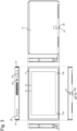
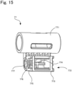
- FIG. 8 is a perspective view of the charging device.
- this charging device 1000 mainly includes a housing 100 formed in an L-shape in a side view, a connector support member 120 attached to the front surface side of the housing 110, and a plate-shaped stand member 130 attached to the back surface of this housing 110.
- these members and accessory members built in these members will be described in detail.
- An upper surface (also referred to as "support surface”) 711 of the base portion 71 has a rectangular shape, and can support the game system 1. Further, a front surface 721 of the extension portion 72 is continuous with the upper surface 711 of the base portion 71 and extends upward, and a portion at which the upper surface 711 of the base portion 71 and the front surface 721 of the extension portion 72 are linked together is curved in an arc shape in a side view. Also, a front opening 73 that is in communication with the internal space of the housing 100 is formed extending from the vicinity of the center of the upper surface 711 of the base portion 71 to the vicinity of the center of the front surface 721 of the extension portion 72.
- the lower surface 722 of the extension portion 72 of the housing is formed by a curved surface that links the lower surface 712 of the base portion 71 and the back surface 723 of the extension portion 72 and is formed in an arc shape in a side view.
- Band-shaped anti-slip members 731 are attached to both sides of this lower surface 722, and these members play the role of slip prevention. It should be noted that the anti-slip members 731 can be made of rubber, silicone, or the like.
- the housing 100 is constituted by a rear panel 100A, which is constituted by the back surface 723 of the extension portion 72, the lower surface 722 of the extension portion 72, and the lower surface of the base portion 71, being combined with a front panel 100B constituted by the outer surfaces other than this rear panel 100A.
- FIG. 12 is a side view of the charging device installed on an installation surface in a tilted state.
- the stand member 130 is formed in a rectangular plate-shape, and is attached to the back surface of the housing 100, that is, the back surface 723 of the extension portion 72. More specifically, the vicinity of an upper end portion of the stand member 130 is attached to the vicinity of an upper end portion of the back surface 723 of the housing 100 so as to be pivotable along an axis line S1 (second axis line) that extends in the left-right direction. Accordingly, as shown in FIG. 12 , the angle of the stand member 130 with respect to the housing 100 can be changed in a state where the lower surface 722 of the housing 100 and the lower end portion 131 of the stand member 130 are in contact with an installation surface D. That is, it is possible to change the angle at which the housing 100 is installed.
- This stand member 130 has substantially the same size as the back surface 723 of the extension portion 72, and its lower end portion 131 is slightly curved forward.
- the lower end portion of the stand member 130 is formed so as to extend along the lower surface 722 of the extension portion 72 when, for example, as shown in FIG. 8 , the stand member 130 is brought into contact with the back surface 723 of the housing 100 by changing the angle of the stand member 130 with respect to the housing 100.
- the vicinity of an upper portion of the front surface of the stand member 130 is provided with a fixing tool 140 that is a portion of the linking mechanism.
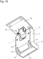
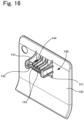
- FIG. 13 is an exploded perspective view of the housing, the linking mechanism, and the stand member
- FIG. 14 is a cross-sectional view taken along line A-A in FIG. 8 .
- a rectangular rear opening 74 is formed in the vicinity of the upper end of the back surface 723 of the extension portion 72, and the rear opening 74 is in communication with the internal space of the housing 100.
- the internal space of the housing 100 accommodates a support member (first site) 75 that constitutes the linking mechanism, a pair of torque hinges (hinge portions) 76 attached to this support member 75, and a pivoting member (second site) 77 attached to the support member 75 via these torque hinges 76.
- a known torque hinge can be used as the torque hinge 76, and the torque hinge 76 includes a cylindrical external tube 761 and a cylindrical shaft portion 762 that is fitted into this external tube 761, and the shaft portion 762 is rotatably attached to the external tube 761. At this time, the shaft portion 762 cannot rotate with respect to the external tube 761 unless a predetermined torque is applied, and as will be described later, the stand member 130 can steplessly adjust the angle of pivoting with respect to the housing 100.
- the external tube 761 is fitted into the support portion 752 of the support member 75, and the shaft portion 762 protrudes from the external tube 761 and is fitted into the pivoting member 77.
- the pivoting member 77 is disposed between the two support portions 752 of the support member 75. More specifically, the pivoting member 77 includes a cylindrical pivoting portion 771 and a second fixing tool (linking portion) 772 attached to an outer circumferential surface of this pivoting portion 771.
- the pivoting portion 771 is disposed between the support portions 752 of the support member 75, and the shaft portions 762 of the torque hinges 76 protruding from the support portions 752 are fitted on the two sides of the pivoting portion 771. Also, as shown in FIG.
- each of the outer side surfaces 775 of the frame member 773 in the left-right direction is provided with an inclined portion 776 that inclines so as to extend inward from the front end opening of the frame member 773 while extending in the left-right direction. Further, a portion of each outer side surface 775 that is inward of the inclined portion 776 is provided with a recessed portion 777, and a protrusion 142 of a fixing piece 141, which will be described later, is fitted to this recessed portion 777.
- a plurality of protruding pieces 143 that are to be fitted to the frame member 773 of the second fixing tool 772 are formed between the two fixing pieces 141.
- These protruding pieces 143 are formed in plate-shapes arranged side-by-side in the left-right direction at predetermined intervals, and the protruding pieces 143 are linked together by the linking portion 144 extending in the left-right direction.
- a positioning portion 774 of the above-described second fixing tool 772 is fitted between the protruding pieces 143.
- four protruding pieces 143 are formed, and as shown in FIG. 17 , the positioning portion 774 is fitted between two protruding pieces 143 at the center.
- the two fixing tools 140 and 772 are brought close to each other, and the protrusions 142 of the fixing tools 141 are slid on the inclined portions 776 of the frame member 773.
- the protrusions 142 of the fixing pieces 141 pass the inclined portions 776, the protrusions 142 are fitted into the recessed portions 777 of the frame member 773.
- the protruding pieces 143 of the first fixing tool 140 are fitted into the frame member 773.
- the protrusions 142 are fitted into the recessed portions 777 in this manner, the two fixing tools 140 and 772 are fixed to each other, and attachment of the stand member 130 to the housing 100 is complete.
- the protrusions 142 of the two fixing pieces 141 separate from the recessed portions 777 of the frame member 773, and the protruding pieces 143 separate from the frame member 773.
- the stand member 130 separates from the housing 100.
- FIG. 19 is a perspective view of the connector support member
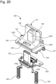
- FIG. 20 is an exploded perspective view of the connector support member
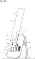
- FIG. 21 is a cross-sectional view showing pivoting of the connector support member.
- the connector support member 120 includes a main body portion 121 that is fitted into the front opening 73 of the housing 100 and has an L-shape in a side view, a connector 122 protruding from this main body portion 121, and a first substrate 1231 connected to this connector 122.
- the upper surface of the first site 1245 and the upper surface 711 of the base portion 71 form an approximately continuous surface
- the front surface of the second site 125 and the front surface 721 of the extension portion 72 also form an approximately continuous surface.
- plate-shaped retaining portions 126 extending in the front-back direction are formed on respective sides of the first site 1245.
- the retaining portions 126 are provided below the upper surface of the first site 1245, and are configured to engage with the inner surface of the housing 100 on respective sides of the front opening 73.
- the retaining portions 126 prevent the main body portion 121 from coming out upward from the front opening 73.
- the rear ends of the retaining portions 126 are each provided with a shaft portion (first axis line) 127 that protrudes in the left-right direction, and this shaft portion 127 is pivotably attached to the inner surface of the base portion 71, that is, a bearing (not shown) provided on the inner surface of the front panel 100B. That is, the shaft portion 127 is disposed rearward of the connector 122. Also, springs (elastic members) 128 are attached to the two ends of the lower surface of the first site 1245, and each spring 128 is supported between the lower surface of the first site 1245 and a lower portion of the internal space of the base portion 71.
- the main body portion 121 is pressed upward by these springs 128, the main body portion 121 is held at the initial position by the retaining portions 126 engaging with the inner surface of the housing 100. If an external force is applied downward to the main body portion 121, the connector 122 pivots downward from the initial position about the shaft portions 127 that serve as the pivoting centers.
- the front surface of the second site 125 is provided with a guide portion 129 extending upward from the portion at which the first site 1245 and the second site 125 are linked together.
- This guide portion 129 is formed in a rectangular parallelepiped shape protruding forward from the front surface of the second site 125, and a front surface of this guide portion 129 constitutes an facing surface 1291 (hatched portion in FIG. 19 ) that is parallel to the back surface 1221 of the connector 122.
- side surfaces (contact surfaces) 1292 oriented in the left-right direction are formed on the two sides of the facing surface 1291.
- This guide portion 129 is fitted to the groove 29 of the above-described game system 1.
- the distance between the female connector 27 and the bottom surface 291 of the groove 29 in the game system 1 is the same as or slightly smaller than the distance between the connector 122 and the facing surface 1291.
- the height of the guide portion 129 protruding from the front surface of the second site 125 is substantially the same as the depth of the groove 29, and the width of the guide portion 129 in the left-right direction is the same as or slightly smaller than the width of the groove 29.
- the distance between the female connector 27 and the back surface of the game system 1 is substantially the same as the distance between the connector 122 and the front surface of the second site 125.
- the guide portion 129 is fitted to the groove 29 of the game system 1 due to such a configuration. Accordingly, the facing surface 1291 faces the bottom surface 291 of the groove 29, that is, the back surface of the game system 1.
- the connector 122 pivots together with the main body portion 121 and the first substrate 1231 due to the above-described configuration. At this time, because the shaft portions 127 are disposed rearward of the connector 122, the connector 122 pivots such that the connector support member 120 sinks downward from the upper surface 711 of the base portion 71 while the upper end of the connector 122 is tilted forward.
- the connector 122 when the connector 122 is located at the initial position, the connector is disposed so as not to protrude from a virtual plane Z that connects the front end of the upper surface 711 of the base portion 71 of the housing 100 and the upper end of the front surface 721 of the extension portion 72.
- FIG. 22 is a perspective view showing the electrical structure inside the housing together with the connector support member.
- the side surface 726 of the extension portion 72 is provided with a side surface opening 725 for an external terminal for connecting an external device.
- an external terminal 78 is provided inside the housing 100 in correspondence with this side surface opening 725.
- This external terminal 78 is a female terminal, and is fixed to a second substrate 781 disposed in the housing 100.
- FIG. 8 is a perspective view showing the electrical structure inside the housing together with the connector support member.
- the side surface 726 of the extension portion 72 is provided with a side surface opening 725 for an external terminal for connecting an external device.
- an external terminal 78 is provided inside the housing 100 in correspondence with this side surface opening 725.
- This external terminal 78 is a female terminal, and is fixed to a second substrate 781 disposed in the housing 100.
- the second substrate 781 is fixed to the inside of the extension portion 72, and accordingly, the opening of the external terminal 78 is supported so as to coincide with the side surface opening 725 of the extension portion 72. Also, as shown in FIG. 22 , the external terminal 78 and the second substrate 781 are electrically connected to each other, and the second substrate 781 and the above-described first substrate 1231 are electrically connected by a flexible flat cable (FFC) 79.
- FFC flexible flat cable
- a charging device 1000 charges the game system 1 connected to the connector 122, by a cable (not shown) connected to the external terminal 78.
- processing for charging is performed by various electronic circuits disposed in the first substrate 1231 and the second substrate 781.
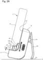
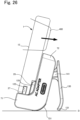
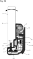
- FIGS. 23 to 25 are cross-sectional views showing the method for attaching the game system to the charging device.
- a method for disposing the game system 1 in the charging device 1000 will be described.
- the stand member 130 is pivoted, the angle between the housing 100 and the stand member 130 is determined as appropriate, and the charging device 1000 is installed on the installation surface D. That is, the lower surface 722 of the housing 100 and the lower end portion 131 of the stand member 130 are in contact with the installation surface D.
- a cable (not shown) connected to a power source is connected to the external terminal 78.
- the display 12 on the front surface of the game system 1 is turned forward, and the orientation of the game system 1 is determined such that the back surface of the game system 1 and the front surface 721 of the extension portion 72 face each other.
- the game system 1 is moved downward such that the connector 122 is inserted into the female connector 27 of the game system 1.
- the guide portion 129 of the charging device 1000 is fitted into the groove 29. Accordingly, the position of the game system 1 is determined (guided) with respect to the charging device 1000 in the left-right direction. If the game system 1 is further lowered, the game system 1 moves downward while being guided by the guide portion 129, and the connector 122 is inserted into the female connector 27.
- the connector support member 120 is pushed upward by the springs 128, in other words, because the connector support member 120 is biased upward, the front end of the connector 122 is still kept in contact with the deep-end portion of the female connector 27. In this manner, the game system 1 is charged.
- the housing 100 is tilted rearward with the anti-slip members 731 on the lower surface 722 of the housing 100 serving as fulcrums.
- the lower end portion 131 of the stand member 130 slides on the installation surface D, and the distance between the lower end portion 131 of the stand member 130 and the lower surface 722 of the housing 100 increases. That is, as shown in FIG. 27 , the stand member 130 pivots such that the angle of the stand member 130 increases with respect to the housing 100. Accordingly, the inclination of the housing 100 can be adjusted.
- the connector 122 is inserted into the game system 1, the connector 122 is tilted together with the game system 1, and the connector support member 120 pivots along with this. At this time, the connector support member 120 pivots such that the connector 122 sinks into the upper surface 711 of the base portion 71. Thus, the connector 122 gradually escapes from the female connector 27 by tilting the game system 1.
- the connector 122 approximately escapes from the female connector 27, and thus if the game system 1 is further tilted, the connector 122 is unlikely to be caught on the female connector 27, and the game system 1 can be detached from the charging device 1000.
- the connector 122 when the connector 122 is inserted into the female connector 27, force is applied to the connector 122 in the insertion process, and there is a possibility that the connector 122 will pivot. If the connector 122 pivots in this manner, there is a possibility that the connector 122 will be caught on the inner portion of the female connector 27, and the connector 122 will not be smoothly inserted.
- the facing surface 1291 that is parallel to the back surface 1221 of the connector 122 comes into contact with the groove 29 of the game system 1, restricting pivoting of the connector 122.
- the connector 122 can be smoothly inserted.
- the guide portion 129 is provided in the connector support member 120, the guide portion 129 can pivot together with the connector 122.
- the positional relationship between the connector 122 and the facing surface 1291 does not change.
- the connector 122 can be easily inserted into the female connector 27.
- the two side surfaces 1292 of the guide portion 129 are configured to come into contact with the two side surfaces 292 in the groove 29, and thus the position of the game system 1 in the left-right direction can be determined (guided) by the guide portion 129.
- this also makes it possible to easily insert the connector 122 into the female connector 27 of the game system 1.
- the above-described exemplary embodiment has a configuration in which, when the connector 122 is inserted into the female connector 27, the connector 122 pivots and the lower surface of the game system 1 comes into contact with the upper surface 711 of the base portion 71 due to the weight of the game system 1 after the connector 122 comes into contact with the deep-end portion of the female connector 27.
- the effective fitting length is short, it is possible to reliably cause current to flow between the connector 122 and the female connector 27.
- the connector support member 120 is pushed upward by the springs 128, the front end of the connector 122 is kept in contact with the deep-end portion of the female connector 27. Thus, it is possible to maintain the state where current flows between the connector 122 and the female connector 27.
- the FFC 79 extends from the rear end portion of the first substrate that supplies power to the connector 122, and the shaft portions 127 are located in the vicinity of the rear end portion of the first substrate 1231. That is, the shaft portions 127 that are the pivoting centers are located near the portion at which the connector 122 and the FFC 79 are connected to each other, and thus even if the first substrate 1231 pivots, the portion at which the first substrate 1231 and the FFC 79 are connected to each other is unlikely to move. Thus, it is possible to reduce failure such as the FFC 79 coming off from the first substrate 1231 due to the FFC 79 excessively moving.
- the connector 122 is disposed so as not to protrude from the virtual plane Z that connects the front end of the upper surface 711 of the base portion 71 of the housing 100 and the upper end of the front surface 721 of the extension portion 72, for example, as shown in FIG. 30 , if the housing 100 is disposed such that the upper surface 711 of the base portion 71 faces the installation surface D, the connector 122 is not in contact with the installation surface D. Thus, even in the case where the housing 100 is installed as in FIG. 30 , it is possible to prevent the connector 122 from coming into contact with the installation surface D and being damaged.
- the stand member 130 is configured to separate from the housing 100, if attempts are made to forcibly increase the angle of the stand member 130, or if the charging device is accidentally stepped on, it is possible to reduce the possibility that the stand member 130 and the housing 100 will be damaged. For example, if the upper end of the housing is stepped on in the state shown in FIG. 31 , the stand member 130 pivots such that the angle of the stand member 130 with respect to the housing 100 increases due to the pressed force. Then, the angle of pivoting increases, and when the upper end 133 of the stand member 130 comes into contact with the upper surface 724 of the housing 100, the stand member 130 cannot pivot anymore.
- the upper end portion of the stand member 130 serves as the fulcrum and the stand member 130 pivots, and the fixing pieces 141 of the stand member 130 separate from the frame member 773 of the second fixing portion 772 along with the pivoting.
- the stand member 130 separates from the housing 100, and thus, it is possible to reduce the possibility of damage such as the case where cracking occurs in the portion at which the housing 100 and the stand member 130 are linked together. Further, even if the stand member 130 separates from the housing 100, the stand member 130 can be easily attached thereto again.
- the support member 75 and the pivoting member 77 are made of a material with high rigidity, and a material with relatively high aesthetic appearance and somewhat low rigidity, such as an ABS resin or polycarbonate, may be used as the material for forming the housing 100 and the stand member 130 that are exposed to the outside. Accordingly, as described above, the support member 75 and the pivoting member 77 are accommodated in the housing 100, and only portions thereof are exposed to the outside, and thus a decrease in the aesthetic appearance of the housing 100 is suppressed. It should be noted that a metal material may be adopted as the material with high rigidity for constituting the support member 75 and the pivoting member 77, for example.
- the guide portion may not have the facing surface 1291 as described above, and it is sufficient that the guide portion has various configurations (a recessed portion, a protruding portion, a groove, and the like) such that the guide portion guides the connector 122 to be inserted into the female connector 27. Further, a configuration may also be adopted in which such a guide portion pivots together with the connector 122.
- the above-described exemplary embodiment has a configuration such that the connector 122 is supported by the connector support member 120, and the connector 122 pivots. That is, the portion of this connector support member 120 that is configured to pivot the connector 122 corresponds to the pivoting mechanism of the present invention.
- the exemplary embodiment has a configuration in which the main body portion 121 of the connector support member 120 pivots, the connector 122 is supported by the first substrate 1231, and the first substrate 1231 is fixed to the main body portion 121.
- a member to which the connector 122 is fixed may be pivotably attached to the housing 100, for example.
- the positions of the pivoting centers need only be located rearward of the connector 122, and are not required to be located downward of the portion of the connector 122 protruding outward from the housing 100, and are not particularly limited.
- the pivoting center (first axis line) may be located above the portion of the connector 122 that protrudes outward from the housing 100.
- the pivoting center may be disposed outside the housing 100.
- the pivoting center may be the shaft portion 127 as described in the exemplary embodiment, or a configuration may be adopted in which a portion at which the members are linked together serves as the pivoting center without providing the pivoting center as a member, and pivots so as to be bent, or a configuration may be adopted in which pivoting is possible by a rail or the like.
- the exemplary embodiment has a configuration in which the connector 122 pivots together with the main body portion 121, the first substrate 1231, and the FFC 79, it is sufficient that the present invention has a configuration in which at least only the connector pivots .
- the connector may also pivot by a member that supports only the connector.
- the first substrate may also be connected to the connector by an FPC, a lead wire, or the like, or the connector 122 may also be connected to another substrate or the external terminal 78.
- the connector support member 120 has the springs (elastic members) 128, but is not limited thereto, and may be another member as long as the connector 122 can be biased toward the initial position.
- the exemplary embodiment has a configuration in which a gap K is formed between the lower surface of the game system 1 and the upper surface 711 of the base portion 71 when the front end of the connector 122 comes into contact with the deep-end portion of the female connector 27 in the process of inserting the connector 122, but the configuration is not limited thereto. That is, when the front end of the connector 122 comes into contact with the deep-end portion of the female connector 27, the lower surface of the game system 1 may also come into contact with the upper surface 711 of the base portion 71. Alternatively, although depending on the effective fitting length, the lower surface of the game system 1 may also come into contact with the upper surface 711 of the base portion 71 before the front end of the connector 122 comes into contact with the deep-end portion of the female connector 27.
- the electric conduction apparatus can also be used for various purposes other than charging an electronic device. That is, the electric conduction apparatus can be electrically connected to an external apparatus by replacing the substrates 1231 and 781 in the housing 100 as appropriate. For example, an image to be displayed on the display of the game system 1 can be displayed on an external display apparatus connected via the external terminal 78. Also, the electric conduction apparatus may be a power supply device for simply supplying power. The electric conduction apparatus according to the present invention can be used to supply power for various purposes other than charging an electronic device.
- the electrical structure within the housing 100 there is no particular limitation on the electrical structure within the housing 100.
- the structure of the external terminal 78 is not particularly limited, and the external terminal 78 may also be various male terminals.
- the position and the shape of the second substrate 781 there is no particular limitation on the housing may be constituted by only the first substrate 1231 and the FFC 79, and the external terminal 78 and the FFC 79 may also be connected to each other.
- the position at which the FFC and the first substrate are connected to each other is located in the rear end portion as described above, it is advantageous, but may be another position.
- a cable is not limited to the FFC 79, and a cable with various shapes may also be used.
- the game system 1 described in the exemplary embodiment is an example, and may also be another game system.
- power can be supplied to various electronic devices other than the game system. That is, an electronic device to which the present invention is applied need only have a predetermined surface provided with a connector insertion port, and is not particularly limited.
- the charging device 1000 of the exemplary embodiment can be used as an apparatus configured to support a device even though the connector support member 120 is detached, in addition to the electronic components such as the connector 122 and the substrate 1231. That is, the charging device 1000 can be used as an apparatus configured to support various devices as long as it has at least the above-described housing 100, stand member 130, and linking mechanism.
- the stand member 130 is configured to separate when attempts are made to forcibly detach the stand member 130, and thus the apparatus can be used as a supporting apparatus having an advantage capable of reducing the possibility that the stand member 130 will be damaged.
- a device that is supported by the supporting apparatus may not be an electronic device, and various devices can be supported.
- the supporting apparatus can be expressed as follows, for example.
- This supporting apparatus is a supporting apparatus configured to support a device, the supporting apparatus including:
- the stand member when attempts are made to forcibly increase the angle of the stand member with respect to the housing, for example, if the angle is the predetermined angle or more, the stand member separates from the housing, and thus it is possible to reduce the possibility that the stand member and the housing will be damaged. On the other hand, even though the stand member separates, the stand member may be then attached to the housing again and used.
- the configuration of the linking mechanism is not particularly limited, and the linking mechanism need only be configured such that the stand member 130 pivots with respect to the housing 100 and separates therefrom when the angle between the stand member 130 and the housing 100 is the predetermined angle or more.
Landscapes
- Engineering & Computer Science (AREA)
- Signal Processing (AREA)
- Theoretical Computer Science (AREA)
- Computer Networks & Wireless Communication (AREA)
- Power Engineering (AREA)
- Human Computer Interaction (AREA)
- General Physics & Mathematics (AREA)
- General Engineering & Computer Science (AREA)
- Physics & Mathematics (AREA)
- Computer Hardware Design (AREA)
- Telephone Set Structure (AREA)
- Charge And Discharge Circuits For Batteries Or The Like (AREA)
- Secondary Cells (AREA)
- Coupling Device And Connection With Printed Circuit (AREA)
- Casings For Electric Apparatus (AREA)
Claims (17)
- Un appareil de conduction électrique (1000), qui est configuré pour supporter un dispositif électronique (1) ayant une surface prédéterminée munie d'un port d'insertion de connecteur (27), une surface frontale (7) avec un écran et une surface dorsale opposée à la surface frontale, et qui est capable d'être électriquement connecté au dispositif électronique (1), l'appareil de conduction électrique (1000) comprenant un boîtier (100) qui possède une partie de base (71) avec une surface configurée pour être tournée vers la surface prédéterminée lorsque le dispositif électronique est électriquement relié à l'appareil de conduction électrique, et une partie en prolongement (72), avec une surface frontale qui s'étend à partir de la surface de la partie de base (71) et une surface dorsale qui est opposée à la surface frontale de la partie en prolongement, la partie de base (71) et la partie en prolongement (72) étant configurées pour donner une forme en L en vue de côté ; et
l'appareil de conduction électrique (1000) comprend en outre :un connecteur (122) qui fait saillie du boîtier (100) et qui est configuré pour être inséré dans le port d'insertion de connecteur (27) ; etun organe support de connecteur (120) auquel est fixé le connecteur (122) et qui est configuré pour faire pivoter le connecteur (122) autour d'un premier axe situé entre la surface dorsale de la partie en prolongement et le connecteur (122) ;dans lequel l'organe support de connecteur (30) comprend en outre une surface apparente (1291) configurée pour venir en contact avec la surface dorsale du dispositif électronique (1) pendant l'insertion du connecteur (122) dans le port d'insertion de connecteur (27) du dispositif électronique (1), etla surface apparente (1291) est disposée entre le connecteur (122) et la surface dorsale de la partie en prolongement et s'étend sensiblement parallèlement à une direction suivant laquelle le connecteur (122) fait saillie, et la surface apparente (1291) est configurée pour pouvoir être pivotée en même temps que le connecteur (122) par l'organe support de connecteur. - L'appareil de conduction électrique (1000) selon la revendication 1,dans lequel le dispositif électronique (1) possède une partie en creux (29) s'étendant dans une direction, opposée à une direction d'insertion du connecteur (122) lorsqu'il est inséré dans le port d'insertion de connecteur (27), s'étendant à partir d'une partie où la surface prédéterminée et la surface dorsale forment entre elles une intersection, etl'organe support de connecteur comprend une partie de guidage dont au moins une partie peut être insérée dans la partie en creux (29), la partie de guidage incluant la surface apparente (1291).
- L'appareil de conduction électrique (1000) selon la revendication 1,dans lequel le dispositif électronique (1) possède une partie en creux (29) s'étendant dans une direction, opposée à une direction d'insertion du connecteur (122) lorsqu'il est inséré dans le port d'insertion de connecteur (27), s'étendant à partir d'une partie où la surface prédéterminée et la surface dorsale forment entre elles une intersection, etl'organe support de connecteur comprend une partie de guidage dont au moins une partie peut être insérée dans la partie en creux (29), la partie de guidage faisant saillie vers le connecteur (122) depuis la surface apparente (1291).
- L'appareil de conduction électrique (1000) selon l'une des revendications 1 à 3, comprenant en outre :un substrat qui est électriquement relié au connecteur (122) ; etun câble (79) s'étendant à partir d'une partie d'extrémité arrière du substrat sur la surface dorsale,dans lequel le substrat est supporté de manière à pouvoir être pivoté en même temps que le connecteur (122) par l'organe support de connecteur, etle premier axe est situé au voisinage de la partie d'extrémité arrière du substrat.
- L'appareil de conduction électrique (1000) selon l'une des revendications 1 à 4,
dans lequel l'organe support de connecteur comprend un organe élastique (128) configuré pour solliciter le connecteur (122) dans une direction suivant laquelle le connecteur (122) est inséré dans le port d'insertion de connecteur (27). - L'appareil de conduction électrique (1000) selon l'une des revendications 1 à 5,dans lequel le dispositif électronique (1) possède une surface frontale s'étendant à partir d'une extrémité frontale de la surface prédéterminée,le boîtier (100) possède une surface support (711) qui est tournée vers la surface prédéterminée du dispositif électronique (1), etla surface support (711) est configurée de telle sorte qu'une partie où la surface prédéterminée et la surface frontale du dispositif électronique (1) forment entre elles une intersection puisse venir en contact avec la surface support (711) lorsque le connecteur (122) inséré dans le port d'insertion de connecteur (27) est séparé du port d'insertion de connecteur (27).
- L'appareil de conduction électrique (1000) selon l'une des revendications 1 à 6,
dans lequel le connecteur (122) est disposé sur le côté du boîtier par rapport à un plan virtuel qui relie une extrémité frontale de la surface de la partie de base (71) et une extrémité supérieure de la surface frontale. - L'appareil de conduction électrique (1000) selon l'une des revendications 1 à 7,
dans lequel l'appareil de conduction électrique (1000) comprend en outre :un organe de maintien (130) qui est solidarisé à une surface dorsale de la partie en prolongement (72) ; etun mécanisme d'articulation configuré pour articuler l'organe de maintien (130) au boîtier (100) de manière à pouvoir pivoter autour d'un second axe, le mécanisme d'articulation étant susceptible d'ajuster un angle entre l'organe de maintien (130) et le boîtier. - L'appareil de conduction électrique (1000) selon la revendication 8,dans lequel le mécanisme d'articulation est configuré pour articuler de manière détachable l'organe de maintien (130) et le boîtier ensemble, etséparer l'organe de maintien (130) du boîtier lorsque l'angle entre l'organe de maintien (130) et le boîtier est un angle prédéterminé ou plus grand.
- L'appareil de conduction électrique (1000) selon la revendication 9,
dans lequel, lorsque l'angle entre l'organe de maintien (130) et le boîtier est l'angle prédéterminé, un site de l'organe de maintien (130) au-dessus du second axe vient en contact avec le boîtier. - L'appareil de conduction électrique (1000) selon l'une des revendications 8 à 10,
dans lequel le mécanisme d'articulation comprend :une partie d'articulation située dans le boîtier, etune paire de parties de fixation (141) qui sont situées dans l'organe de maintien (130) et fixées de manière détachables à la partie d'articulation de manière à prendre en sandwich deux extrémités de la partie d'articulation dans une direction suivant le second axe. - L'appareil de conduction électrique (1000) selon la revendication 11,
dans lequel le mécanisme d'articulation comprend en outre une partie d'emboîtement (144) qui est située entre la paire de parties de fixation (141) de l'organe de maintien (130) et qui peut venir en prise avec la partie d'articulation. - L'appareil de conduction électrique (1000) selon la revendication 11 ou 12,
dans lequel une partie inclinée est formée dans au moins l'une des parties où les parties de fixation (141) et la partie d'articulation sont en contact entre elles dans un état où les parties de fixation (141) et la partie d'articulation sont fixes l'une par rapport à l'autre, et les parties de fixation (141) et la partie d'articulation sont configurées pour être fixées l'une à l'autre après coulissement au-dessus de la partie inclinée. - L'appareil de conduction électrique (1000) selon l'une des revendications 11 à 13,
dans lequel le mécanisme d'articulation comprend :un premier site (75) qui est situé dans la partie d'extension (72),un second site (77) qui inclut la partie d'articulation, etune partie de charnière (76) qui articule le premier site (75) au second site (77) et qui permet au premier site (75) et au second site (77) de pivoter l'un par rapport à l'autre autour du second axe. - L'appareil de conduction électrique (1000) selon la revendication 14,
dans lequel un matériau servant à former le premier site (75) et le second site (77) présente une rigidité qui est supérieure à celle d'un matériau servant à former le boîtier. - L'appareil de conduction électrique (1000) selon la revendication 15,
dans lequel le premier site (75) et le second site (77) sont réalisés en un matériau de résine contenant des fibres de verre, et au moins une partie du premier site (75) et du second site (77) est logée dans le boîtier. - L'appareil de conduction électrique (1000) selon l'une des revendications 1 à 16,
dans lequel le dispositif électronique (1) peut être rechargé lorsque le connecteur (122) est inséré dans le port d'insertion de connecteur (27) du dispositif électronique (1).
Applications Claiming Priority (1)
| Application Number | Priority Date | Filing Date | Title |
|---|---|---|---|
| JP2018037582A JP6511178B1 (ja) | 2018-03-02 | 2018-03-02 | 通電装置 |
Publications (3)
| Publication Number | Publication Date |
|---|---|
| EP3534236A2 EP3534236A2 (fr) | 2019-09-04 |
| EP3534236A3 EP3534236A3 (fr) | 2019-10-23 |
| EP3534236B1 true EP3534236B1 (fr) | 2023-08-09 |
Family
ID=64661206
Family Applications (1)
| Application Number | Title | Priority Date | Filing Date |
|---|---|---|---|
| EP18211105.4A Active EP3534236B1 (fr) | 2018-03-02 | 2018-12-07 | Appareil de conduction électrique |
Country Status (3)
| Country | Link |
|---|---|
| US (2) | US10554002B2 (fr) |
| EP (1) | EP3534236B1 (fr) |
| JP (1) | JP6511178B1 (fr) |
Families Citing this family (12)
| Publication number | Priority date | Publication date | Assignee | Title |
|---|---|---|---|---|
| EP3751679B1 (fr) * | 2018-02-05 | 2023-04-05 | Panasonic Intellectual Property Management Co., Ltd. | Mécanisme de maintien de connecteur |
| JP1615864S (fr) * | 2018-03-02 | 2018-10-15 | ||
| JP6511178B1 (ja) | 2018-03-02 | 2019-05-15 | 任天堂株式会社 | 通電装置 |
| US10784618B2 (en) * | 2018-06-26 | 2020-09-22 | Hongfeng Wang | Transmission line with a plug having a foldable bracket |
| US10940385B2 (en) * | 2019-07-30 | 2021-03-09 | Sony Interactive Entertainment Inc. | Controller add-on device with customizable presets |
| USD946515S1 (en) * | 2020-08-17 | 2022-03-22 | Ugreen Group Limited | Charger |
| JP1724049S (ja) * | 2020-11-30 | 2022-09-06 | 浄水器の取り外し可能なディスプレイ | |
| JP1724050S (ja) * | 2020-11-30 | 2022-09-06 | 浄水器の取り外し可能なディスプレイ | |
| CN113154199A (zh) * | 2021-04-20 | 2021-07-23 | 深圳市金拓达科技有限公司 | 一种游戏支架 |
| US11626686B2 (en) * | 2021-06-14 | 2023-04-11 | Havis, Inc. | Tablet docking station |
| WO2025049867A2 (fr) * | 2023-08-30 | 2025-03-06 | Belkin International, Inc. | Accessoires de dispositif, appareils et procédés |
| US12385594B1 (en) * | 2025-03-10 | 2025-08-12 | Pioneer Square Brands, Inc. | Stand system for portable electronic device |
Citations (4)
| Publication number | Priority date | Publication date | Assignee | Title |
|---|---|---|---|---|
| US20130241470A1 (en) * | 2012-03-13 | 2013-09-19 | Samsung Electronics Co., Ltd. | Universal dock for portable phone |
| EP2001207B1 (fr) * | 2006-03-27 | 2014-04-30 | NEC Corporation | Support de chargeur de bureau |
| US20170117729A1 (en) * | 2015-10-27 | 2017-04-27 | Nintendo Co., Ltd. | Charger and charging system |
| EP2629172B1 (fr) * | 2012-02-16 | 2018-01-03 | Samsung Electronics Co., Ltd | Socle universel de type bureau |
Family Cites Families (64)
| Publication number | Priority date | Publication date | Assignee | Title |
|---|---|---|---|---|
| US6113409A (en) * | 1998-10-05 | 2000-09-05 | Samsung Electronics Co., Ltd. | Connecting apparatus for cartridge of learning device |
| JP2000134808A (ja) * | 1998-10-27 | 2000-05-12 | Japan Radio Co Ltd | 携帯電子機器用充電器 |
| US6193546B1 (en) * | 1999-03-16 | 2001-02-27 | Ericsson Inc. | Support assembly for personal electronic device and method for using the same |
| US6366450B1 (en) * | 1999-12-09 | 2002-04-02 | Gateway, Inc. | Hideaway integrated docking cradle |
| KR100422016B1 (ko) * | 2001-08-21 | 2004-03-11 | 삼성전자주식회사 | 휴대용 단말기의 크레이들 장치 |
| JP2004088729A (ja) * | 2002-06-25 | 2004-03-18 | Fuji Photo Film Co Ltd | デジタルカメラシステム |
| US7719830B2 (en) * | 2005-05-09 | 2010-05-18 | Apple Inc. | Universal docking station for hand held electronic devices |
| TW568408U (en) * | 2003-05-14 | 2003-12-21 | High Tech Comp Corp | Slide structure |
| JP4330502B2 (ja) * | 2004-08-11 | 2009-09-16 | 三洋電機株式会社 | フローティング構造のコネクタ |
| JP2006147305A (ja) * | 2004-11-18 | 2006-06-08 | Mitsumi Electric Co Ltd | フローティングコネクタ |
| TWM268757U (en) * | 2004-12-07 | 2005-06-21 | High Tech Comp Corp | Recoverable connector structure and cradle having the connector structure |
| US7580255B2 (en) * | 2005-08-24 | 2009-08-25 | Apple Inc. | Docking station for hand held electronic devices |
| CN100463301C (zh) * | 2005-10-12 | 2009-02-18 | 鸿富锦精密工业(深圳)有限公司 | 电子连接装置 |
| CN101356867B (zh) * | 2006-01-04 | 2012-01-11 | 罗技欧洲公司 | 用于个人音频装置的通用辅助组件连接系统 |
| US7620176B2 (en) | 2006-07-26 | 2009-11-17 | Samsung Electronics Co., Ltd. | Adjustable view stand |
| CN200959420Y (zh) * | 2006-08-29 | 2007-10-10 | 富士康(昆山)电脑接插件有限公司 | 具有弹性结构的连接器 |
| US7738247B2 (en) * | 2007-01-05 | 2010-06-15 | Sdi Technologies Inc. | Removable and replaceable docking unit |
| US20080259550A1 (en) * | 2007-04-18 | 2008-10-23 | Microtips Technology Inc. | Cradle for handheld electronic device |
| KR101420876B1 (ko) * | 2007-11-16 | 2014-07-17 | 삼성전자주식회사 | 휴대용 단말기의 거치대 |
| JP5057119B2 (ja) * | 2007-12-14 | 2012-10-24 | 富士通株式会社 | 保持台および情報処理システム |
| JP4623748B2 (ja) * | 2008-04-18 | 2011-02-02 | Smk株式会社 | フローティング構造を有するコネクタ |
| US8559172B2 (en) * | 2008-05-02 | 2013-10-15 | Norman R. Byrne | Docking station |
| CA2726477C (fr) * | 2008-06-09 | 2017-02-14 | Norman R. Byrne | Station d'accueil a usage avec un centre d'alimentation et de donnees |
| US7931494B2 (en) * | 2008-12-18 | 2011-04-26 | Janam Technologies, Llc | Flexible holder for a connector having a receptacle with multiple degrees of motion |
| JP5103406B2 (ja) * | 2009-01-16 | 2012-12-19 | 京セラ株式会社 | 置き台 |
| TWI380514B (en) * | 2009-07-09 | 2012-12-21 | Hon Hai Prec Ind Co Ltd | Electronic connector and electronic device using the same |
| US8113873B1 (en) * | 2009-09-22 | 2012-02-14 | Western Digital Technologies, Inc. | Pivot assisted storage device unloading mechanism |
| JP5443934B2 (ja) * | 2009-10-06 | 2014-03-19 | ヤマハ株式会社 | 接続機器 |
| US20110099507A1 (en) * | 2009-10-28 | 2011-04-28 | Google Inc. | Displaying a collection of interactive elements that trigger actions directed to an item |
| KR101701922B1 (ko) * | 2009-11-17 | 2017-02-02 | 삼성전자 주식회사 | 휴대용 기기의 도킹장치 |
| US8223483B2 (en) * | 2010-01-04 | 2012-07-17 | Apple Inc. | Dock with moveable connector for display device |
| US8366468B2 (en) * | 2010-08-18 | 2013-02-05 | Carnevali Jeffrey D | Connector isolator system |
| US8821173B2 (en) * | 2010-08-18 | 2014-09-02 | Jeffrey D. Carnevali | Docking station having preload and connector isolator system |
| US8366469B2 (en) * | 2010-08-18 | 2013-02-05 | Carnevali Jeffrey D | Connector isolator system |
| US8780547B2 (en) * | 2010-12-27 | 2014-07-15 | Seiko Epson Corporation | Projector |
| TWI414929B (zh) * | 2011-02-23 | 2013-11-11 | Pegatron Corp | 樞軸裝置及擴充基座 |
| CN102758993B (zh) * | 2011-04-26 | 2015-12-16 | 富泰华工业(深圳)有限公司 | 底座及使用该底座的电子设备 |
| TWI420775B (zh) * | 2011-05-26 | 2013-12-21 | 鴻海精密工業股份有限公司 | 具有安全功能的充電座 |
| US8853998B2 (en) * | 2011-06-30 | 2014-10-07 | Blackberry Limited | Portable electronic device dock having a connector movable in response to a magnetic force |
| US8545247B2 (en) * | 2011-06-30 | 2013-10-01 | Blackberry Limited | Dock for a portable electronic device |
| JP2013025885A (ja) * | 2011-07-15 | 2013-02-04 | Sony Corp | 接続装置 |
| US8929065B2 (en) * | 2011-08-23 | 2015-01-06 | L&P Property Management Company | Docking station with ruggedized case |
| US8848361B2 (en) * | 2011-09-02 | 2014-09-30 | Sdi Technologies | Adjustable docking apparatus |
| JP2013131365A (ja) * | 2011-12-21 | 2013-07-04 | Sony Corp | 接続装置及び電子機器 |
| TWI502310B (zh) * | 2011-12-28 | 2015-10-01 | Wistron Corp | 電子裝置之擴充座及其連接器機構 |
| US9160124B2 (en) * | 2012-09-07 | 2015-10-13 | Apple Inc. | Compliant mount for connector |
| US8721356B2 (en) * | 2012-09-11 | 2014-05-13 | Apple Inc. | Dock with compliant connector mount |
| US8986029B2 (en) * | 2012-09-11 | 2015-03-24 | Apple Inc. | Dock connector with compliance mechanism |
| US9201453B2 (en) * | 2012-10-26 | 2015-12-01 | Apple Inc. | Self-retracting connector for docking device |
| US9093849B2 (en) * | 2013-01-07 | 2015-07-28 | Superior Communications, Inc. | Universal charging dock with a wall mount |
| US9836086B2 (en) * | 2013-08-02 | 2017-12-05 | Belkin International, Inc. | Adjustable docking stand with ejector and method of providing and using the same |
| US9454183B2 (en) * | 2013-08-02 | 2016-09-27 | Belkin International, Inc. | Adjustable docking stand and method of providing and using the same |
| US9178299B2 (en) * | 2014-03-24 | 2015-11-03 | Dxo Labs Sas | Device comprising an electronic connector to establish a connection with an electronic device |
| US9429995B2 (en) * | 2014-05-15 | 2016-08-30 | Norman R. Byrne | Docking station for electronic devices |
| JP6006260B2 (ja) * | 2014-05-19 | 2016-10-12 | 任天堂株式会社 | 充電システム |
| US9466927B2 (en) * | 2014-09-08 | 2016-10-11 | Apple Inc. | Docking station with integral device support structure |
| US9778690B2 (en) * | 2014-09-30 | 2017-10-03 | Apple Inc. | Adaptive docking station |
| KR20160105669A (ko) * | 2015-02-27 | 2016-09-07 | 삼성전자주식회사 | 커넥터 모듈 및 이를 포함하는 잠금 장치 |
| US9874902B2 (en) * | 2015-03-10 | 2018-01-23 | BPM Products, LLC | Mobile device docking station |
| JP6074534B2 (ja) * | 2015-06-12 | 2017-02-01 | 任天堂株式会社 | ゲームコントローラ |
| US10610776B2 (en) * | 2015-06-12 | 2020-04-07 | Nintendo Co., Ltd. | Supporting device, charging device and controller system |
| EP3482805B1 (fr) * | 2016-10-06 | 2020-01-29 | Nintendo Co., Ltd. | Accessoire |
| US10209740B2 (en) * | 2017-01-31 | 2019-02-19 | Henge Docks Llc | Ejection mechanism for docked electronic device |
| JP6511178B1 (ja) | 2018-03-02 | 2019-05-15 | 任天堂株式会社 | 通電装置 |
-
2018
- 2018-03-02 JP JP2018037582A patent/JP6511178B1/ja active Active
- 2018-11-27 US US16/201,091 patent/US10554002B2/en active Active
- 2018-12-07 EP EP18211105.4A patent/EP3534236B1/fr active Active
-
2019
- 2019-12-13 US US16/714,022 patent/US10978843B2/en active Active
Patent Citations (4)
| Publication number | Priority date | Publication date | Assignee | Title |
|---|---|---|---|---|
| EP2001207B1 (fr) * | 2006-03-27 | 2014-04-30 | NEC Corporation | Support de chargeur de bureau |
| EP2629172B1 (fr) * | 2012-02-16 | 2018-01-03 | Samsung Electronics Co., Ltd | Socle universel de type bureau |
| US20130241470A1 (en) * | 2012-03-13 | 2013-09-19 | Samsung Electronics Co., Ltd. | Universal dock for portable phone |
| US20170117729A1 (en) * | 2015-10-27 | 2017-04-27 | Nintendo Co., Ltd. | Charger and charging system |
Also Published As
| Publication number | Publication date |
|---|---|
| EP3534236A2 (fr) | 2019-09-04 |
| JP6511178B1 (ja) | 2019-05-15 |
| US10978843B2 (en) | 2021-04-13 |
| US20200119505A1 (en) | 2020-04-16 |
| US10554002B2 (en) | 2020-02-04 |
| EP3534236A3 (fr) | 2019-10-23 |
| US20190273350A1 (en) | 2019-09-05 |
| JP2019154147A (ja) | 2019-09-12 |
Similar Documents
| Publication | Publication Date | Title |
|---|---|---|
| EP3534236B1 (fr) | Appareil de conduction électrique | |
| US12059611B2 (en) | Game controller | |
| JP7850310B2 (ja) | ゲームコントローラ | |
| JP7403604B2 (ja) | 通電装置 |
Legal Events
| Date | Code | Title | Description |
|---|---|---|---|
| PUAI | Public reference made under article 153(3) epc to a published international application that has entered the european phase |
Free format text: ORIGINAL CODE: 0009012 |
|
| STAA | Information on the status of an ep patent application or granted ep patent |
Free format text: STATUS: THE APPLICATION HAS BEEN PUBLISHED |
|
| AK | Designated contracting states |
Kind code of ref document: A2 Designated state(s): AL AT BE BG CH CY CZ DE DK EE ES FI FR GB GR HR HU IE IS IT LI LT LU LV MC MK MT NL NO PL PT RO RS SE SI SK SM TR |
|
| AX | Request for extension of the european patent |
Extension state: BA ME |
|
| PUAL | Search report despatched |
Free format text: ORIGINAL CODE: 0009013 |
|
| AK | Designated contracting states |
Kind code of ref document: A3 Designated state(s): AL AT BE BG CH CY CZ DE DK EE ES FI FR GB GR HR HU IE IS IT LI LT LU LV MC MK MT NL NO PL PT RO RS SE SI SK SM TR |
|
| AX | Request for extension of the european patent |
Extension state: BA ME |
|
| RIC1 | Information provided on ipc code assigned before grant |
Ipc: H01R 35/04 20060101ALI20190917BHEP Ipc: B60R 11/02 20060101ALN20190917BHEP Ipc: H04M 1/04 20060101ALI20190917BHEP Ipc: H04B 1/3877 20150101ALI20190917BHEP Ipc: G06F 1/16 20060101AFI20190917BHEP Ipc: H01R 13/516 20060101ALI20190917BHEP Ipc: H02J 7/00 20060101ALI20190917BHEP |
|
| STAA | Information on the status of an ep patent application or granted ep patent |
Free format text: STATUS: REQUEST FOR EXAMINATION WAS MADE |
|
| 17P | Request for examination filed |
Effective date: 20200415 |
|
| RBV | Designated contracting states (corrected) |
Designated state(s): AL AT BE BG CH CY CZ DE DK EE ES FI FR GB GR HR HU IE IS IT LI LT LU LV MC MK MT NL NO PL PT RO RS SE SI SK SM TR |
|
| STAA | Information on the status of an ep patent application or granted ep patent |
Free format text: STATUS: EXAMINATION IS IN PROGRESS |
|
| 17Q | First examination report despatched |
Effective date: 20210421 |
|
| GRAP | Despatch of communication of intention to grant a patent |
Free format text: ORIGINAL CODE: EPIDOSNIGR1 |
|
| STAA | Information on the status of an ep patent application or granted ep patent |
Free format text: STATUS: GRANT OF PATENT IS INTENDED |
|
| INTG | Intention to grant announced |
Effective date: 20221219 |
|
| GRAJ | Information related to disapproval of communication of intention to grant by the applicant or resumption of examination proceedings by the epo deleted |
Free format text: ORIGINAL CODE: EPIDOSDIGR1 |
|
| STAA | Information on the status of an ep patent application or granted ep patent |
Free format text: STATUS: EXAMINATION IS IN PROGRESS |
|
| GRAP | Despatch of communication of intention to grant a patent |
Free format text: ORIGINAL CODE: EPIDOSNIGR1 |
|
| STAA | Information on the status of an ep patent application or granted ep patent |
Free format text: STATUS: GRANT OF PATENT IS INTENDED |
|
| INTC | Intention to grant announced (deleted) | ||
| INTG | Intention to grant announced |
Effective date: 20230411 |
|
| GRAS | Grant fee paid |
Free format text: ORIGINAL CODE: EPIDOSNIGR3 |
|
| GRAA | (expected) grant |
Free format text: ORIGINAL CODE: 0009210 |
|
| STAA | Information on the status of an ep patent application or granted ep patent |
Free format text: STATUS: THE PATENT HAS BEEN GRANTED |
|
| AK | Designated contracting states |
Kind code of ref document: B1 Designated state(s): AL AT BE BG CH CY CZ DE DK EE ES FI FR GB GR HR HU IE IS IT LI LT LU LV MC MK MT NL NO PL PT RO RS SE SI SK SM TR |
|
| P01 | Opt-out of the competence of the unified patent court (upc) registered |
Effective date: 20230629 |
|
| REG | Reference to a national code |
Ref country code: GB Ref legal event code: FG4D |
|
| REG | Reference to a national code |
Ref country code: CH Ref legal event code: EP |
|
| REG | Reference to a national code |
Ref country code: IE Ref legal event code: FG4D |
|
| REG | Reference to a national code |
Ref country code: DE Ref legal event code: R096 Ref document number: 602018054922 Country of ref document: DE |
|
| REG | Reference to a national code |
Ref country code: LT Ref legal event code: MG9D |
|
| REG | Reference to a national code |
Ref country code: NL Ref legal event code: MP Effective date: 20230809 |
|
| REG | Reference to a national code |
Ref country code: AT Ref legal event code: MK05 Ref document number: 1598263 Country of ref document: AT Kind code of ref document: T Effective date: 20230809 |
|
| PG25 | Lapsed in a contracting state [announced via postgrant information from national office to epo] |
Ref country code: GR Free format text: LAPSE BECAUSE OF FAILURE TO SUBMIT A TRANSLATION OF THE DESCRIPTION OR TO PAY THE FEE WITHIN THE PRESCRIBED TIME-LIMIT Effective date: 20231110 |
|
| PG25 | Lapsed in a contracting state [announced via postgrant information from national office to epo] |
Ref country code: IS Free format text: LAPSE BECAUSE OF FAILURE TO SUBMIT A TRANSLATION OF THE DESCRIPTION OR TO PAY THE FEE WITHIN THE PRESCRIBED TIME-LIMIT Effective date: 20231209 |
|
| PG25 | Lapsed in a contracting state [announced via postgrant information from national office to epo] |
Ref country code: SE Free format text: LAPSE BECAUSE OF FAILURE TO SUBMIT A TRANSLATION OF THE DESCRIPTION OR TO PAY THE FEE WITHIN THE PRESCRIBED TIME-LIMIT Effective date: 20230809 Ref country code: RS Free format text: LAPSE BECAUSE OF FAILURE TO SUBMIT A TRANSLATION OF THE DESCRIPTION OR TO PAY THE FEE WITHIN THE PRESCRIBED TIME-LIMIT Effective date: 20230809 Ref country code: PT Free format text: LAPSE BECAUSE OF FAILURE TO SUBMIT A TRANSLATION OF THE DESCRIPTION OR TO PAY THE FEE WITHIN THE PRESCRIBED TIME-LIMIT Effective date: 20231211 Ref country code: NO Free format text: LAPSE BECAUSE OF FAILURE TO SUBMIT A TRANSLATION OF THE DESCRIPTION OR TO PAY THE FEE WITHIN THE PRESCRIBED TIME-LIMIT Effective date: 20231109 Ref country code: NL Free format text: LAPSE BECAUSE OF FAILURE TO SUBMIT A TRANSLATION OF THE DESCRIPTION OR TO PAY THE FEE WITHIN THE PRESCRIBED TIME-LIMIT Effective date: 20230809 Ref country code: LV Free format text: LAPSE BECAUSE OF FAILURE TO SUBMIT A TRANSLATION OF THE DESCRIPTION OR TO PAY THE FEE WITHIN THE PRESCRIBED TIME-LIMIT Effective date: 20230809 Ref country code: LT Free format text: LAPSE BECAUSE OF FAILURE TO SUBMIT A TRANSLATION OF THE DESCRIPTION OR TO PAY THE FEE WITHIN THE PRESCRIBED TIME-LIMIT Effective date: 20230809 Ref country code: IS Free format text: LAPSE BECAUSE OF FAILURE TO SUBMIT A TRANSLATION OF THE DESCRIPTION OR TO PAY THE FEE WITHIN THE PRESCRIBED TIME-LIMIT Effective date: 20231209 Ref country code: HR Free format text: LAPSE BECAUSE OF FAILURE TO SUBMIT A TRANSLATION OF THE DESCRIPTION OR TO PAY THE FEE WITHIN THE PRESCRIBED TIME-LIMIT Effective date: 20230809 Ref country code: GR Free format text: LAPSE BECAUSE OF FAILURE TO SUBMIT A TRANSLATION OF THE DESCRIPTION OR TO PAY THE FEE WITHIN THE PRESCRIBED TIME-LIMIT Effective date: 20231110 Ref country code: FI Free format text: LAPSE BECAUSE OF FAILURE TO SUBMIT A TRANSLATION OF THE DESCRIPTION OR TO PAY THE FEE WITHIN THE PRESCRIBED TIME-LIMIT Effective date: 20230809 Ref country code: AT Free format text: LAPSE BECAUSE OF FAILURE TO SUBMIT A TRANSLATION OF THE DESCRIPTION OR TO PAY THE FEE WITHIN THE PRESCRIBED TIME-LIMIT Effective date: 20230809 |
|
| PG25 | Lapsed in a contracting state [announced via postgrant information from national office to epo] |
Ref country code: PL Free format text: LAPSE BECAUSE OF FAILURE TO SUBMIT A TRANSLATION OF THE DESCRIPTION OR TO PAY THE FEE WITHIN THE PRESCRIBED TIME-LIMIT Effective date: 20230809 |
|
| PG25 | Lapsed in a contracting state [announced via postgrant information from national office to epo] |
Ref country code: ES Free format text: LAPSE BECAUSE OF FAILURE TO SUBMIT A TRANSLATION OF THE DESCRIPTION OR TO PAY THE FEE WITHIN THE PRESCRIBED TIME-LIMIT Effective date: 20230809 |
|
| PG25 | Lapsed in a contracting state [announced via postgrant information from national office to epo] |
Ref country code: SM Free format text: LAPSE BECAUSE OF FAILURE TO SUBMIT A TRANSLATION OF THE DESCRIPTION OR TO PAY THE FEE WITHIN THE PRESCRIBED TIME-LIMIT Effective date: 20230809 Ref country code: RO Free format text: LAPSE BECAUSE OF FAILURE TO SUBMIT A TRANSLATION OF THE DESCRIPTION OR TO PAY THE FEE WITHIN THE PRESCRIBED TIME-LIMIT Effective date: 20230809 Ref country code: ES Free format text: LAPSE BECAUSE OF FAILURE TO SUBMIT A TRANSLATION OF THE DESCRIPTION OR TO PAY THE FEE WITHIN THE PRESCRIBED TIME-LIMIT Effective date: 20230809 Ref country code: EE Free format text: LAPSE BECAUSE OF FAILURE TO SUBMIT A TRANSLATION OF THE DESCRIPTION OR TO PAY THE FEE WITHIN THE PRESCRIBED TIME-LIMIT Effective date: 20230809 Ref country code: DK Free format text: LAPSE BECAUSE OF FAILURE TO SUBMIT A TRANSLATION OF THE DESCRIPTION OR TO PAY THE FEE WITHIN THE PRESCRIBED TIME-LIMIT Effective date: 20230809 Ref country code: CZ Free format text: LAPSE BECAUSE OF FAILURE TO SUBMIT A TRANSLATION OF THE DESCRIPTION OR TO PAY THE FEE WITHIN THE PRESCRIBED TIME-LIMIT Effective date: 20230809 Ref country code: SK Free format text: LAPSE BECAUSE OF FAILURE TO SUBMIT A TRANSLATION OF THE DESCRIPTION OR TO PAY THE FEE WITHIN THE PRESCRIBED TIME-LIMIT Effective date: 20230809 |
|
| REG | Reference to a national code |
Ref country code: DE Ref legal event code: R097 Ref document number: 602018054922 Country of ref document: DE |
|
| PG25 | Lapsed in a contracting state [announced via postgrant information from national office to epo] |
Ref country code: IT Free format text: LAPSE BECAUSE OF FAILURE TO SUBMIT A TRANSLATION OF THE DESCRIPTION OR TO PAY THE FEE WITHIN THE PRESCRIBED TIME-LIMIT Effective date: 20230809 |
|
| PLBE | No opposition filed within time limit |
Free format text: ORIGINAL CODE: 0009261 |
|
| STAA | Information on the status of an ep patent application or granted ep patent |
Free format text: STATUS: NO OPPOSITION FILED WITHIN TIME LIMIT |
|
| 26N | No opposition filed |
Effective date: 20240513 |
|
| PG25 | Lapsed in a contracting state [announced via postgrant information from national office to epo] |
Ref country code: SI Free format text: LAPSE BECAUSE OF FAILURE TO SUBMIT A TRANSLATION OF THE DESCRIPTION OR TO PAY THE FEE WITHIN THE PRESCRIBED TIME-LIMIT Effective date: 20230809 |
|
| REG | Reference to a national code |
Ref country code: CH Ref legal event code: PL |
|
| PG25 | Lapsed in a contracting state [announced via postgrant information from national office to epo] |
Ref country code: LU Free format text: LAPSE BECAUSE OF NON-PAYMENT OF DUE FEES Effective date: 20231207 |
|
| PG25 | Lapsed in a contracting state [announced via postgrant information from national office to epo] |
Ref country code: MC Free format text: LAPSE BECAUSE OF FAILURE TO SUBMIT A TRANSLATION OF THE DESCRIPTION OR TO PAY THE FEE WITHIN THE PRESCRIBED TIME-LIMIT Effective date: 20230809 |
|
| REG | Reference to a national code |
Ref country code: BE Ref legal event code: MM Effective date: 20231231 |
|
| PG25 | Lapsed in a contracting state [announced via postgrant information from national office to epo] |
Ref country code: MC Free format text: LAPSE BECAUSE OF FAILURE TO SUBMIT A TRANSLATION OF THE DESCRIPTION OR TO PAY THE FEE WITHIN THE PRESCRIBED TIME-LIMIT Effective date: 20230809 Ref country code: LU Free format text: LAPSE BECAUSE OF NON-PAYMENT OF DUE FEES Effective date: 20231207 |
|
| REG | Reference to a national code |
Ref country code: IE Ref legal event code: MM4A |
|
| PG25 | Lapsed in a contracting state [announced via postgrant information from national office to epo] |
Ref country code: IE Free format text: LAPSE BECAUSE OF NON-PAYMENT OF DUE FEES Effective date: 20231207 |
|
| PG25 | Lapsed in a contracting state [announced via postgrant information from national office to epo] |
Ref country code: BE Free format text: LAPSE BECAUSE OF NON-PAYMENT OF DUE FEES Effective date: 20231231 |
|
| PG25 | Lapsed in a contracting state [announced via postgrant information from national office to epo] |
Ref country code: CH Free format text: LAPSE BECAUSE OF NON-PAYMENT OF DUE FEES Effective date: 20231231 |
|
| PG25 | Lapsed in a contracting state [announced via postgrant information from national office to epo] |
Ref country code: IE Free format text: LAPSE BECAUSE OF NON-PAYMENT OF DUE FEES Effective date: 20231207 Ref country code: CH Free format text: LAPSE BECAUSE OF NON-PAYMENT OF DUE FEES Effective date: 20231231 Ref country code: BE Free format text: LAPSE BECAUSE OF NON-PAYMENT OF DUE FEES Effective date: 20231231 |
|
| PG25 | Lapsed in a contracting state [announced via postgrant information from national office to epo] |
Ref country code: BG Free format text: LAPSE BECAUSE OF FAILURE TO SUBMIT A TRANSLATION OF THE DESCRIPTION OR TO PAY THE FEE WITHIN THE PRESCRIBED TIME-LIMIT Effective date: 20230809 |
|
| PG25 | Lapsed in a contracting state [announced via postgrant information from national office to epo] |
Ref country code: BG Free format text: LAPSE BECAUSE OF FAILURE TO SUBMIT A TRANSLATION OF THE DESCRIPTION OR TO PAY THE FEE WITHIN THE PRESCRIBED TIME-LIMIT Effective date: 20230809 |
|
| PG25 | Lapsed in a contracting state [announced via postgrant information from national office to epo] |
Ref country code: CY Free format text: LAPSE BECAUSE OF FAILURE TO SUBMIT A TRANSLATION OF THE DESCRIPTION OR TO PAY THE FEE WITHIN THE PRESCRIBED TIME-LIMIT; INVALID AB INITIO Effective date: 20181207 |
|
| PG25 | Lapsed in a contracting state [announced via postgrant information from national office to epo] |
Ref country code: HU Free format text: LAPSE BECAUSE OF FAILURE TO SUBMIT A TRANSLATION OF THE DESCRIPTION OR TO PAY THE FEE WITHIN THE PRESCRIBED TIME-LIMIT; INVALID AB INITIO Effective date: 20181207 |
|
| PG25 | Lapsed in a contracting state [announced via postgrant information from national office to epo] |
Ref country code: TR Free format text: LAPSE BECAUSE OF FAILURE TO SUBMIT A TRANSLATION OF THE DESCRIPTION OR TO PAY THE FEE WITHIN THE PRESCRIBED TIME-LIMIT Effective date: 20230809 |
|
| PGFP | Annual fee paid to national office [announced via postgrant information from national office to epo] |
Ref country code: DE Payment date: 20251028 Year of fee payment: 8 |
|
| PGFP | Annual fee paid to national office [announced via postgrant information from national office to epo] |
Ref country code: GB Payment date: 20251030 Year of fee payment: 8 |
|
| PGFP | Annual fee paid to national office [announced via postgrant information from national office to epo] |
Ref country code: FR Payment date: 20251110 Year of fee payment: 8 |