EP3534476A1 - Installationsdose - Google Patents
Installationsdose Download PDFInfo
- Publication number
- EP3534476A1 EP3534476A1 EP19160350.5A EP19160350A EP3534476A1 EP 3534476 A1 EP3534476 A1 EP 3534476A1 EP 19160350 A EP19160350 A EP 19160350A EP 3534476 A1 EP3534476 A1 EP 3534476A1
- Authority
- EP
- European Patent Office
- Prior art keywords
- installation box
- installation
- magnet
- lid
- fastening means
- Prior art date
- Legal status (The legal status is an assumption and is not a legal conclusion. Google has not performed a legal analysis and makes no representation as to the accuracy of the status listed.)
- Granted
Links
Images


Classifications
-
- H—ELECTRICITY
- H02—GENERATION; CONVERSION OR DISTRIBUTION OF ELECTRIC POWER
- H02G—INSTALLATION OF ELECTRIC CABLES OR LINES, OR OF COMBINED OPTICAL AND ELECTRIC CABLES OR LINES
- H02G3/00—Installations of electric cables or lines or protective tubing therefor in or on buildings, equivalent structures or vehicles
- H02G3/02—Details
- H02G3/08—Distribution boxes; Connection or junction boxes
- H02G3/12—Distribution boxes; Connection or junction boxes for flush mounting
- H02G3/121—Distribution boxes; Connection or junction boxes for flush mounting in plain walls
-
- H—ELECTRICITY
- H02—GENERATION; CONVERSION OR DISTRIBUTION OF ELECTRIC POWER
- H02G—INSTALLATION OF ELECTRIC CABLES OR LINES, OR OF COMBINED OPTICAL AND ELECTRIC CABLES OR LINES
- H02G3/00—Installations of electric cables or lines or protective tubing therefor in or on buildings, equivalent structures or vehicles
- H02G3/02—Details
- H02G3/08—Distribution boxes; Connection or junction boxes
- H02G3/18—Distribution boxes; Connection or junction boxes providing line outlets
- H02G3/185—Floor outlets and access cups
Definitions
- the invention relates to an installation box for electrical connections.
- installation sockets are used for the installation of electrical switches, sockets, lamps, appliances or for branching at the designated places in the building, which are embedded in concrete.
- installation boxes for example, inlet boxes, ceiling dowels, flush boxes, junction boxes, people or loudspeaker installation housing and the like understood.
- Such installation boxes typically have a cylindrical or cuboid housing with bottom and / or lid, which form an accessible via an installation opening installation space.
- the installation opening can be closed by a lid.
- On the periphery side or in the bottom of these installation boxes also often have a plurality of sleeves and adapters, which are typically provided for the attachment of plastic pipes, in particular corrugated pipes, for the implementation of connection cables.
- Installation of the installation box in the area of a concrete surface takes place before concreting.
- Conventional installation boxes are fastened, for example, with nails or by means of hot melt adhesive to a formwork element, that their installation opening faces the formwork.
- solutions are known in which the installation boxes can be attached by means of magnets to a metal formwork of the concrete wall. This is advantageous because the position of the installation box can be easily changed even after the initial attachment.
- the attachment to metal formwork is also increasingly in concrete foundries, which are specialized in the production of prefabricated elements and assemblies. For example, Ceilings and wall elements several meters in length and width are prefabricated so that they can be easily assembled and assembled on the construction site.
- a disadvantage of the known from the prior art doses is that the magnet is difficult to remove again.
- An object of the invention is to show an improved installation box, which allows easy and secure temporary fixation on a magnetic surface.
- the inventive installation box usually includes a can body with an installation opening, which can be closed by a lid if necessary.
- the can body has a can wall which surrounds an installation space which is accessible from the outside via the installation opening. Furthermore, this can have a fixed to the can wall bottom of the can.
- the bottom of the can also be designed as a removable lid, which allows access to the installation space via a second installation opening.
- At least one of the lids may be operatively connected to the can wall via a hinge.
- the hinge may be a ribbon hinge that integrally connects the can wall and the corresponding lid.
- the bottom of the can and / or the lid can be attached to one of the installation space pioneering mounting side have a recess which serves for temporarily receiving a magnet.
- a peripheral edge can be arranged around the recess, which edge adjoins the magnet directly or is arranged at a certain distance from it.
- the edge can serve in the assembled state as a support or sealant of the lid relative to the formwork and prevent that when pouring concrete reaches a surface surrounded by the peripheral edge or penetrates to the magnet.
- the can bottom and / or the lid comprise a fastening means, which serves for the temporary holding of the magnet with respect to the lid, or the can.
- the attachment can be done via a frictional connection (such as a clamping) and / or by positive locking (such as an undercut).
- the one or more fastening means for the magnet are - as will be explained in more detail below - advantageously arranged in the region of the depression or adjacent thereto.
- the fastener in a withdrawal direction of the magnet may cooperate therewith via an undercut which holds the magnet in the withdrawal direction until it reaches a defined level of force and then releases it.
- the removal direction is advantageously arranged perpendicular to the shuttering wall. Other embodiments are possible.
- the force level is advantageously set lower than the holding force of the magnet relative to the formwork. Good results are achieved when the force level corresponds to 30% to 60% of the holding force of the magnet.
- the fastener on the inside of the lid and / or the can bottom in the installation room the can be arranged.
- the magnet can be operatively connected to the fastening means, for example via a pin, a pin or the like.
- the lid and / or the bottom of the can may have a passage opening between the recess and the fastening means.
- the passage opening may be arranged in a membrane-like partition, which itself serves as a fastening means or is part of the same.
- the fastening means comprises one or more inwardly projecting, at least partially deformable ribs.
- the ribs are designed and arranged in such a way that they hold the magnet in a controlled manner and / or, for example, a pin or pin fastened thereto, and release them in the removal direction only when the force level described above has been reached.
- an undercut this can for example be formed on the pin, so that the ribs can engage in the mounted state of the magnet in this.
- the undercut has with advantage in Entformungscardi a certain slope. The angle of the slope is chosen with respect to the Entformungsoplasty so that the force level is not exceeded during the removal.
- the bevel may be formed on the pin and / or the rib.
- the ribs may face radially inwardly or at an angle to an inner side of the passage opening, so that the ribs do not point in the direction of a central axis.
- the ribs are advantageously at least partially deformable, so that depending on the diameter of a pin to be performed, the ribs can change their angle and thus optimally fixing (pinching) the respective pin.
- the lid and / or the bottom of the can comprise holding means for holding the lid and / or the bottom of the can on the can wall.
- the magnet which serves to hold the lid, or the box, arranged in the center of the lid.
- the cover Adjacent to the magnet (s), the cover may have on the mounting side, which is facing in the installed state of the formwork, a structured surface, which is designed so that better adheres to the plaster after casting plaster.
- the structured surface advantageously has a structure which comprises recesses and / or elevations.
- the structured surface is in this case on the lid and / or the bottom of the can between the peripheral edge and the magnet.
- the recess on the mounting side (after removing the magnet through the formwork) can also be used to record a display device.
- a correspondingly shaped insert can be embedded in the recess of the lid.
- the insert may comprise a display device which after plastering the lid protrudes from the plaster and a fitter indicates at which position the plastered wall is the installation box.
- an installation kit suitable for repeated use of a magnet can be provided with at least one installation box without built-in magnets and a single magnet detached therefrom.
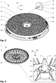
- FIG. 1 shows a variant of an inventive installation box 1.
- the installation box comprises a can body 2 and a lid 3, which are shown in a disassembled state.
- the can body 2 comprises a can bottom 4 and a can wall 5 adjacent to the can bottom 4, which together form an installation space 6.
- On the can wall 5 is located for the introduction of cables or pipes in the installation space 6 one or more pipe inlet 14.
- the can bottom 4 opposite is an installation opening 7 which allows access to the installation space 6 and of the lid 3 in an assembled state (not here shown) is closed. Also visible are the distributed over the circumference of the lid 3 multiple holding means 25, which serve to operatively connect the lid 3 with the can body 2 respectively for closing the installation opening 7.
- the cover 3 comprises a depression 9 on a mounting side 8 pointing away from the installation space 6, into which a magnet 10 which is held detachably by a fastening means 11 is arranged.
- This is used for temporary attachment of the installation box 1 to a metallic formwork wall (not visible).
- a circumferential edge 22 is arranged, which is arranged at a certain distance from the recess 9 and the magnet 10.
- the edge 22 serves in the assembled state as a support or sealant of the lid 3 with respect to the formwork and prevents the concrete from being poured onto a surface surrounded by the peripheral edge 22 or advances as far as the magnet 10.
- the surface between the edge 22 and the recess 9 is formed as a structured surface 23. This is plastered after the removal of the formwork and the magnet 10.
- the structured surface 23 in this case supports the connection of the plaster with the installation box. 1
- FIG. 2 shows the lid 3 and the magnet 10 in a disassembled state. It can be seen that adjacent to the recess 9, which accommodates the magnet 10, further recesses 24 are arranged, which may optionally serve for the manual removal of the magnet 10 from the lid 3.
- the magnet is operatively connected via a pin 13 with the fastening means 11, which non-magnetic must be trained.
- the pin 13 and the magnet are here via a thread 15, arranged at a first end 20 of the pin, operatively connected to each other.
- the thickening 19, together with the cover 3, forms an undercut 12 in a removal direction (z) of the magnet 10.
- the removal direction is arranged perpendicularly to the shuttering wall in the case shown.
- the pin 13 is inserted through a through opening 16 through the lid 3, as in FIG. 3 and in the sectional view of FIG. 5 (according to FIG. 4 ) shown in more detail.
- the undercut 12 through the lid 3, or its wall (formed by the material between the Mounting side 8 and the inside 17) and the thickening 19 of the pin 13 is formed.
- the magnet 10 can be fastened by a further clamping means 26.
- the magnet 10 can be held on the one hand by the side surfaces of the recess 9, respectively, clamped.
- the pin 13 can also be held by the corresponding ribs 18 in the radial direction, which thus also act as clamping means 26.
- FIG. 6 shows a second possible application of the recess 9 of the lid 3, after the magnet 10 has been separated by the shutter from the lid 3.
- the undercut 12 is designed so that it holds the magnet until it reaches a defined level of force and then releases it.
- the force level is set lower than the corresponding holding force of the magnet 10 relative to the formwork.
- the lid 3 and the can body 2 located behind it are plastered together with the wall.
- a correspondingly shaped insert 27 can be embedded in the recess 9 and / or the recess 24 of the lid 3.
- the insert 27 may include a display device 28 which protrudes from the plaster after plastering the lid 3 and indicates to a fitter at which position of the plastered wall, the installation box 1 is located.
- a display device 28 which protrudes from the plaster after plastering the lid 3 and indicates to a fitter at which position of the plastered wall, the installation box 1 is located.
- Through opening 2 can body 17 inside 3 cover 18 ribs 4 can bottom 19 thickening 5 can wall 20 First end (tenon) 6 installation space 21 Second end (tenon) 7 installation opening 22 edge 8th mounting side 23 Structured surface 9 deepening 24 recess 10 magnet 25 holding means 11 fastener 26 clamping means 12 undercut 27 commitment 13 spigot 28 display device 14 tube insertion 15 thread
Landscapes
- Engineering & Computer Science (AREA)
- Architecture (AREA)
- Civil Engineering (AREA)
- Structural Engineering (AREA)
- Forms Removed On Construction Sites Or Auxiliary Members Thereof (AREA)
Abstract
Description
- Die Erfindung betrifft eine Installationsdose für elektrische Anschlüsse.
- In Bauwerken aus Beton werden für das Anbringen elektrischer Schalter, Steckdosen, Lampen, Apparate oder für Verzweigungen an den dazu vorgesehenen Stellen im Gebäude Installationsdosen verwendet, welche einbetoniert werden. Unter Installationsdosen werden beispielsweise Einlasskästen, Deckendübel, Unterputzdosen, Verteilerdosen, Leuten- oder Lautsprechereinbaugehäuse und dergleichen verstanden. Solche Installationsdosen weisen typischerweise ein zylinder- oder quaderförmiges Gehäuse mit Boden und/oder Deckel auf, welche einen über eine Installationsöffnung zugänglichen Installationsraum ausbilden. Je nach Ausführungsform kann die Installationsöffnung durch einen Deckel verschlossen werden. Umfangsseitig in der Seitenwand oder im Boden weisen diese Installationsdosen zudem oft eine Mehrzahl von Muffen und Adaptern auf, welche typischerweise zur Befestigung von Plastikrohren, insbesondere Wellrohren, zur Durchführung von Anschlusskabeln vorgesehen sind.
- Der Einbau der Installationsdose im Bereich einer Betonoberfläche (Wände, Decken, Böden) erfolgt vor dem Betonieren. Herkömmliche Installationsdosen werden beispielsweise mit Nägeln oder mittels Heisskleber derart an einem Schalungselement befestigt, dass ihre Installationsöffnung der Schalung zugewandt ist. Weiterhin sind Lösungen bekannt, bei denen die Installationsdosen mittels Magneten an einer Metallschalung der Betonwand befestigt werden können. Dies ist vorteilhaft, da die Position der Installationsdose auch nach der initialen Befestigung noch leicht wieder verändert werden kann. Die Befestigung an Metallschalungen erfolgt zudem immer häufiger in Betongiesswerken, welche auf die Fertigung von vorgefertigten Elemente und Baugruppen spezialisiert sind. Z.B. werden Decken und Wandelemente mit mehreren Metern Länge und Breite so vorgefertigt, dass sie auf der Baustelle einfach montiert und zusammengefügt werden können. Bei diesen vorgefertigten Elementen und Baugruppen werden zumindest die Verrohrung für die Elektrokabel und/oder Wasserleitungen, etc. bereits im Werk verlegt und dann eingegossen. Dabei kommen mit Vorteil Schalungen aus Metall zum Einsatz, welche es erlauben die einzubringenden Elemente mittels Magneten temporär auf der Oberfläche der späteren Wand zu befestigen.
- Aus dem Stand der Technik sind Installationsdosen bekannt, in welche Permanentmagnete fest eingebaut sind. Diese können in der Dose selbst oder in einem Deckel der Dose, welcher typischerweise die Installationsöffnung der Installationsdose vor dem Eindringen von flüssigem Beton schützt, angebracht sein. In der Vergangenheit wurden diese Magnete zunächst vorzugsweise so eingebettet, dass diese nach dem Giessen des Betons aus Kostengründen wiederverwendet werden konnten. Beispiele für eine solche Technologie sind z.B. die
EP1848080B1 oder dieDE4220720A1 , wo entweder nur der Magnet oder dieser gemeinsam mit einer dafür vorgesehenen Haltevorrichtung wiederverwendet werden kann. - Ein Nachteil der aus dem Stand der Technik bekannten Dosen besteht darin, dass der Magnet nur schwer wieder entfernt werden kann.
- Eine Aufgabe der Erfindung besteht darin eine verbesserte Installationsdose zu zeigen, welche einfach und sicher eine temporäre Fixierung an einer magnetischen Oberfläche ermöglicht.
- Die erfindungsgemässe Installationsdose umfasst in der Regel einen Dosenkörper mit einer Installationsöffnung, welche bei Bedarf durch einen Deckel verschlossen werden kann. Der Dosenkörper weist eine Dosenwand auf, welche einen Installationsraum umgibt, der über die Installationsöffnung von aussen zugänglich ist. Weiterhin kann diese Dose einen fest mit der Dosenwand verbundenen Dosenboden aufweisen. Alternativ kann der Dosenboden auch als abnehmbarer Deckel ausgestaltet sein, welcher über eine zweite Installationsöffnung einen Zugang zum Installationsraum ermöglicht. Zumindest einer der Deckel kann über ein Scharnier mit der Dosenwand wirkverbunden sein. Beim Scharnier kann es sich beispielsweise um ein Bandscharnier handeln, welches die Dosenwand und den entsprechenden Deckel integral verbindet. Der Dosenboden und/oder der Deckel können an einer von dem Installationsraum wegweisenden Montageseite eine Vertiefung aufweisen, welche zur temporären Aufnahme eines Magneten dient. Um die Vertiefung kann ein umlaufender Rand angeordnet sein, welcher direkt an den Magneten angrenzt oder in einem gewissen Abstand von diesem angeordnet ist. Der Rand kann im montierten Zustand als Auflage- bzw. Dichtungsmittel des Deckels gegenüber der Schalung dienen und verhindern, dass beim Vergiessen Beton auf eine von dem umlaufenden Rand umgebene Fläche gelangt bzw. bis zum Magneten vordringt.
- Der Dosenboden und/oder der Deckel umfassen ein Befestigungsmittel, welches zur temporären Halterung des Magnets gegenüber dem Deckel, bzw. der Dose dient. Die Befestigung kann über einen Reibschluss (wie z.B. eine Klemmung) und/oder durch Formschluss (wie z.B. einen Hinterschnitt) erfolgen. Das oder die Befestigungsmittel für den Magneten, sind hierzu - wie nachfolgend genauer erläutert wird - mit Vorteil im Bereich der Vertiefung oder angrenzend an diese angeordnet. Zum Beispiel kann das Befestigungsmittel in einer Entnahmerichtung des Magnets mit diesem über einen Hinterschnitt zusammenwirken, welcher den Magneten in der Entnahmerichtung bis zum Erreichen eines definierten Kraftniveaus hält und danach freigibt. Die Entnahmerichtung ist dabei mit Vorteil senkrecht zur Schalungswand angeordnet. Andere Ausgestaltungen sind möglich. Das Kraftniveau ist dabei mit Vorteil tiefer angesetzt als die Haltekraft des Magnets gegenüber der Schalung. Gute Resultate werden erzielt, wenn das Kraftniveau 30% bis 60% der Haltekraft des Magnets entspricht. Je nach Anwendungsgebiet kann das Befestigungsmittel auf der Innenseite des Deckels und/oder des Dosenbodens im Installationsraum der Dose angeordnet sein. Der Magnet kann mit dem Befestigungsmittel z.B. über einen Stift, einen Zapfen oder dergleichen wirkverbunden sein. Der Deckel und/oder der Dosenboden können bei Bedarf zwischen der Vertiefung und dem Befestigungsmittel eine Durchgangsöffnung aufweisen. Die Durchgangsöffnung kann in einer membranartigen Trennwand angeordnet sein, welche selber als Befestigungsmittel dient oder Bestandteil desselben ist.
- In einer Variante umfasst das Befestigungsmittel eine oder mehrere nach innen abstehende, zumindest bereichsweise deformierbare Rippen. Die Rippen sind so ausgestaltet und angeordnet, dass sie den Magneten und/oder z.B. einen an diesem befestigten Stift oder Zapfen kontrolliert halten und erst beim Erreichen des oben beschriebenen Kraftniveaus in Entnahmerichtung freigeben. Bei der Verwendung eines Hinterschnitts kann dieser z.B. am Stift angeformt sein, so dass die Rippen im montierten Zustand des Magnets in diesen eingreifen können. Der Hinterschnitt weist mit Vorteil in Entformungsrichtung eine gewisse Schräge auf. Der Winkel der Schräge ist mit Bezug auf die Entformungsrichtung so gewählt, dass das Kraftniveau bei der Entnahme nicht überschritten wird. Die Schräge kann am Stift und/oder der Rippe ausgebildet sein. Je nach Ausführungsform können die Rippen radial nach innen weisen oder in einem Winkel zu einer Innenseite der Durchgangsöffnung stehen, so dass die Rippen nicht in Richtung einer Mittelachse zeigen. Für einen guten Halt des Magnets in dem Deckel und/oder dem Dosenboden sind die Rippen mit Vorteil zumindest teilweise verformbar, so dass je nach Durchmesser eines durchzuführenden Zapfens die Rippen ihren Winkel verändern können und so den jeweiligen Zapfen optimal festlegen (klemmen). Für eine einfache Herstellung mittels Spritzguss ist es zudem vorteilhaft, wenn die Rippen in einer Entformungsrichtung des Spritzgusswerkzeuges hinterschnittfrei entformbar sind.
- Je nach Ausgestaltung umfassen der Deckel und/oder der Dosenboden Haltemittel zum Halten des Deckels und/oder des Dosenbodens an der Dosenwand.
- In der Regel ist der Magnet, welcher zur Halterung des Deckels, bzw. der Dose dient, im Zentrum des Deckels angeordnet. Je nach Ausgestaltung kann aber auch mehr als ein Magnet vorgesehen werden. Angrenzend an den oder die Magnete kann der Deckel auf der Montageseite, welche im montierten Zustand der Schalung zugewendet ist, eine strukturierte Fläche aufweisen, welche so ausgestaltet ist, dass daran nach dem Vergiessen Verputz besser haftet. Die strukturierte Fläche weist mit Vorteil eine Struktur auf, welche Vertiefungen und/oder Erhebungen umfasst. Bevorzugterweise liegt die strukturierte Fläche hierbei auf dem der Deckel und/oder der Dosenboden zwischen dem umlaufenden Rand und dem Magneten.
- Um eine Position der Installationsdose in der verputzen Wand besser auswindig machen zu können, kann die Vertiefung auf der Montageseite (nach dem Entfernen des Magnets durch die Schalung) ebenfalls dazu genutzt werden eine Anzeigevorrichtung aufzunehmen. Vor dem Verputzen der Wand, kann in die Vertiefung des Deckels ein entsprechend geformter Einsatz eingelassen werden. Der Einsatz kann eine Anzeigevorrichtung umfassen, welche nach dem Verputzen des Deckels aus dem Putz hervorsteht und einem Monteur anzeigt, an welcher Position der verputzen Wand sich die Installationsdose befindet.
- Zur Montage einer oder mehrerer entsprechenden Installationsdosen, wie zuvor beschrieben, können verschiedene Installationsdosen ohne einen darin verbauten Magneten mit einem einzelnen von den Installationsdosen losgelösten Magneten, wie zuvor beschrieben, verwendet werden. Dadurch, dass der Magnet nach dem Giessen und Aushärten der Betonwand von den Installationsdosen abgetrennt wird, kann dieser in Kombinationen mit verschiedenen Dosen (ohne entsprechend verbauten Magneten) wiederverwertet werden. Somit kann ein Installationskit geeignet zur wiederholten Verwendung eines Magnets bereitgestellt werden mit mindestens einer Installationsdose ohne eingebauten Magneten und einen davon losgelösten einzelnen Magneten.
- Anhand der in den nachfolgenden Figuren gezeigten Ausführungsbeispiele und der dazugehörigen Beschreibung werden Aspekte der Erfindung näher erläutert. Es zeigen:
- Fig. 1
- Eine Variante einer Installationsdose 1 gemäss der Erfindung in einer perspektivischen Ansicht mit einem Deckel 3 losgelöst von einem Dosenkörper 2;
- Fig. 2
- der Deckel 3 gemäss
Figur 1 mit einem Magneten 10 in einem auseinandergebauten Zustand in einer perspektivischen Ansicht von oben; - Fig. 3
- der Deckel 3 gemäss
Figur 1 mit einem Magneten 10 in einem zusammengebauten Zustand in einer perspektivischen Ansicht von unten; - Fig. 4
- der Deckel 3 gemäss
Figur 3 in dem zusammengebauten Zustand in einer Ansicht von oben; - Fig. 5
- der Deckel 3 in dem zusammengebauten Zustand in einer Schnittansicht gemäss
Figur 4 ; - Fig. 6
- ein Deckels 3 einer Installationsdose 1 gemäss
Figur 1 mit einem Einsatz 27 und einer Anzeigevorrichtung 28. -
Figur 1 zeigt eine Variante einer erfindungsgemässen Installationsdose 1. Die Installationsdose umfasst einen Dosenkörper 2 und einen Deckel 3, welche in einem auseinandergebauten Zustand dargestellt sind. Der Dosenkörper 2 umfasst einen Dosenboden 4 und eine an den Dosenboden 4 angrenzende Dosenwand 5, welche gemeinsam einen Installationsraum 6 bilden. An der Dosenwand 5 befindet sich zur Einführung von Kabeln oder Rohren in den Installationsraum 6 ein bzw. mehrere Rohreinführung 14. Dem Dosenboden 4 gegenüberliegend befindet sich eine Installationsöffnung 7 welche Zugang zum Installationsraum 6 erlaubt und von dem Deckel 3 in einem montierten Zustand (hier nicht dargestellt) verschlossen ist. Ebenfalls sichtbar sind die über den Umfang des Deckels 3 verteilten multiplen Haltemittel 25, welche zum Wirkverbinden des Deckels 3 mit dem Dosenkörper 2 respektive zum Verschliessen der Installationsöffnung 7 dienen. - In der dargestellten Variante umfasst der Deckel 3 an einer von dem Installationsraum 6 wegweisenden Montageseite 8 eine Vertiefung 9, in welche ein durch ein Befestigungsmittel 11 lösbar gehaltener Magnet 10 angeordnet ist. Dieser dient zur temporären Befestigung der Installationsdose 1 an einer metallischen Schalungswand (nicht sichtbar). Um die Vertiefung 9 ist ein umlaufender Rand 22 angeordnet, welcher in einem gewissen Abstand zu der Vertiefung 9 bzw. dem Magneten 10 angeordnet ist. Der Rand 22 dient im montierten Zustand als Auflage- bzw. Dichtungsmittel des Deckels 3 gegenüber der Schalung und verhindert, dass beim Vergiessen Beton auf eine von dem umlaufenden Rand 22 umgebene Fläche gelangt bzw. bis zum Magneten 10 vordringt. Die Fläche zwischen dem Rand 22 und der Vertiefung 9 ist als eine strukturiere Fläche 23 ausgebildet. Diese wird nach der Entfernung der Schalung und des Magnets 10 verputzt. Die strukturierte Fläche 23 unterstützt hierbei die Verbindung des Verputzes mit der Installationsdose 1.
- Die Vertiefung 9 und der Magnet 10 sind im Detail in
Figur 2 zu erkennen.Figur 2 zeigt den Deckel 3 und den Magneten 10 in einem auseinandergebauten Zustand. Es ist zu erkennen, dass angrenzend an die Vertiefung 9, welche den Magneten 10 aufnimmt, weitere Aussparungen 24 angeordnet sind, die ggf. zum manuellen Entnehmen des Magnets 10 aus dem Deckel 3 dienen können. Der Magnet ist über einen Zapfen 13 mit dem Befestigungsmittel 11 wirkverbunden, welcher nichtmagnetisch ausgebildet sein muss. Der Zapfen 13 und der Magnet sind hier über ein Gewinde 15, angeordnet an einem ersten Ende 20 des Zapfens, miteinander wirkverbunden. An einem zweiten Ende 21 des Zapfens 13 befindet sich weitergehend eine Verdickung 19. Die Verdickung 19 bildet zusammen mit dem Deckel 3 einen Hinterschnitt 12 in eine Entnahmerichtung (z) des Magnets 10. Die Entnahmerichtung ist in dem gezeigten Fall senkrecht zur Schalungswand angeordnet. Zur Bildung des Hinterschnitts 12 wird der Zapfen 13 durch eine Durchgangsöffnung 16 durch den Deckel 3 gesteckt, wie inFigur 3 und in der Schnittdarstellung derFigur 5 (gemässFigur 4 ) näher dargestellt. Auf einer Innenseite 17 des Deckels 3, welche zum Installationsraum 6 hingewandt ist, ragt der Zapfen 13 aus der Durchgangsöffnung 16 heraus. Von der Innenseite 17 und der Durchgangsöffnung 16 abgehende Rippen 18 bilden in der gezeigten Variante mit der Verdickung 19 den Hinterschnitt 12. Es ist jedoch ebenfalls denkbar, dass der Hinterschnitt 12 durch den Deckel 3, bzw. dessen Wandung (gebildet durch das Material zwischen der Montageseite 8 und der Innenseite 17) und der Verdickung 19 des Zapfens 13 gebildet wird. Zusätzlich oder alternativ zu dem Hinterschnitt 12 kann der Magnet 10 durch eine weitere Klemmmittel 26 befestigt werden. In der gezeigten Variante kann der Magnet 10 einerseits von den Seitenflächen der Vertiefung 9 gehalten, respektive geklemmt, werden. Andererseits kann alternativ oder in Ergänzung ebenfalls der Zapfen 13 von den entsprechenden Rippen 18 in radiale Richtung gehalten werden, welche somit ebenfalls als Klemmmittel 26 fungieren. -
Figur 6 zeigt eine zweite mögliche Anwendung der Vertiefung 9 des Deckels 3, nachdem der Magnet 10 durch die Schalung von dem Deckel 3 abgetrennt wurde. Hierzu ist der Hinterschnitt 12 so ausgeführt, dass dieser den Magnet bis zum Erreichen eines definierten Kraftniveaus hält und danach freigibt. Das Kraftniveau ist tiefer angesetzt als die entsprechende Haltekraft des Magnets 10 gegenüber der Schalung. Wenn die Schalung also entfernt wird, haftet der Magnet 10 an der Schalung während der Deckel 3 auf dem Dosenkörper 2 in der gegossenen Wand verbleibt. In einem weiteren Bearbeitungsschritt wird der Deckel 3 und der dahinterliegende Dosenkörper 2 gemeinsam mit der Wand verputzt. Vor dem Verputzen der Wand, kann in die Vertiefung 9 und/oder die Aussparung 24 des Deckels 3 ein entsprechend geformter Einsatz 27 eingelassen werden. Der Einsatz 27 kann eine Anzeigevorrichtung 28 umfassen, welche nach dem Verputzen des Deckels 3 aus dem Putz hervorsteht und einem Monteur anzeigt, an welcher Position der verputzen Wand sich die Installationsdose 1 befindet.LISTE DER BEZUGSZEICHEN 1 Installationsdose 16 Durchgangsöffnung 2 Dosenkörper 17 Innenseite 3 Deckel 18 Rippen 4 Dosenboden 19 Verdickung 5 Dosenwand 20 Erstes Ende (Zapfen) 6 Installationsraum 21 Zweites Ende (Zapfen) 7 Installationsöffnung 22 Rand 8 Montageseite 23 Strukturierte Fläche 9 Vertiefung 24 Aussparung 10 Magnet 25 Haltemittel 11 Befestigungsmittel 26 Klemmmittel 12 Hinterschnitt 27 Einsatz 13 Zapfen 28 Anzeigevorrichtung 14 Rohreinführung 15 Gewinde
Claims (15)
- Installationsdose (1) umfassend einen Dosenkörper (2) und einen Deckel (3),a. wobei der Dosenkörper (2) einen Dosenboden (4) und eine an den Dosenboden (4) angrenzende Dosenwand (5) umfasst, welche einen Installationsraum (6) bilden;b. dem Dosenboden (4) gegenüberliegend befindet sich eine Installationsöffnung (7) welche Zugang zum Installationsraum (6) erlaubt und von dem Deckel (3) in einem montierten Zustand verschlossen ist;c. der Dosenboden (4) und/oder der Deckel (3) an einer von dem Installationsraum (6) wegweisenden Montageseite (8) eine Vertiefung (9) umfasst, in welcher ein durch ein Befestigungsmittel (11) lösbar gehaltener Magnet (10) angeordnet ist, der zum temporären Befestigen der Installationsdose (1) an einer Schalungswand dient.
- Installationsdose (1) gemäss Patentanspruch 1, dadurch gekennzeichnet, dass der Magnet (10) gegenüber dem Befestigungsmittel (11) durch Formschluss und/oder durch Reibschluss gehalten ist.
- Installationsdose (1) gemäss einem der vorangehenden Patentansprüche, dadurch gekennzeichnet, dass zwischen dem Magnet (10) und dem Befestigungsmittel (11) ein Hinterschnitt ausgebildet ist.
- Installationsdose (1) gemäss einem der vorangehenden Patentansprüche, dadurch gekennzeichnet, dass die Wirkverbindung zwischen dem Befestigungsmittel (11) und dem Magnet (10) so ausgebildet ist, dass der Magnet (10) beim Erreichen eines definierten Kraftniveaus in einer Entnahmerichtung (z) freigegeben wird.
- Installationsdose (1) nach Patentanspruch 4, dadurch gekennzeichnet, dass das Kraftniveau 30% bis 60% der Haltekraft des Magnets (10) entspricht.
- Installationsdose (1) gemäss einem der vorangehenden Patentansprüche, dadurch gekennzeichnet, dass der Dosenboden (4) als abnehmbarer Deckel (3) ausgestaltet ist, welcher über eine zweite Installationsöffnung Zugang zum Installationsraum (6) ermöglicht.
- Installationsdose (1) gemäss einem der vorangehenden Patentansprüche, dadurch gekennzeichnet, dass das Befestigungsmittel (11) auf einer Innenseite (17) des Deckels (3) im Bereich des Installationsraumes (6) angeordnet ist.
- Installationsdose (1) gemäss Patentanspruch 7, dadurch gekennzeichnet, dass zwischen dem Befestigungsmittel (11) und der Vertiefung (9) eine Durchgangsöffnung (16) angeordnet ist.
- Installationsdose (1) gemäss einem der vorangehenden Patentansprüche, dadurch gekennzeichnet, dass das Befestigungsmittel (11) mindestens eine deformierbare Rippe (18) umfasst.
- Installationsdose (1) gemäss einem der vorangehenden Patentansprüche, dadurch gekennzeichnet, dass die Vertiefung (9) von einem umlaufenden Rand (22) umgeben ist, welcher zur Abstützung der Installationsdose (1) gegenüber der Metallschalung dient.
- Installationsdose (1) gemäss Patentanspruch 10, dadurch gekennzeichnet, dass der umlaufende Rand (22) eine Dichtung umfasst.
- Installationsdose (1) gemäss Patentanspruch 10 oder 11, dadurch gekennzeichnet, dass der Deckel (3) und/oder der Dosenboden (4) zwischen dem umlaufenden Rand (22) und dem Magneten (10) eine strukturierte Fläche (23) aufweist.
- Installationsdose (1) gemäss einem der vorangehenden Patentansprüche, dadurch gekennzeichnet, dass der Magnet (10) über einen Zapfen (13) mit dem Befestigungsmittel (11) wirkverbunden ist.
- Installationsdose (1) gemäss Patentanspruch 13 dadurch gekennzeichnet, dass der Zapfen (13) an einem Ende (20) zur Bildung des Hinterschnitts (12) eine radiale Verdickung (19) aufweist.
- Installationsdose (1) gemäss einem der vorangehenden Patentansprüche, dadurch gekennzeichnet, dass die Vertiefung (9) alternativ einen Einsatz (27) mit einer Anzeigevorrichtung (28) zum Anzeigen einer Position der Installationsdose (1) aufnimmt.
Applications Claiming Priority (1)
| Application Number | Priority Date | Filing Date | Title |
|---|---|---|---|
| DE202018101204.5U DE202018101204U1 (de) | 2018-03-02 | 2018-03-02 | Installationsdose |
Publications (2)
| Publication Number | Publication Date |
|---|---|
| EP3534476A1 true EP3534476A1 (de) | 2019-09-04 |
| EP3534476B1 EP3534476B1 (de) | 2022-08-03 |
Family
ID=62069272
Family Applications (1)
| Application Number | Title | Priority Date | Filing Date |
|---|---|---|---|
| EP19160350.5A Active EP3534476B1 (de) | 2018-03-02 | 2019-03-01 | Installationsdose |
Country Status (2)
| Country | Link |
|---|---|
| EP (1) | EP3534476B1 (de) |
| DE (1) | DE202018101204U1 (de) |
Cited By (3)
| Publication number | Priority date | Publication date | Assignee | Title |
|---|---|---|---|---|
| EP3923430A1 (de) | 2020-06-10 | 2021-12-15 | Kaiser GmbH & Co. KG | Installationsteil für den betonbau |
| DE202022102774U1 (de) | 2022-05-19 | 2022-06-27 | Primo Gmbh | Magneteinrichtung zur magnetischen Befestigung von Betoneinbauteilen auf einer Schalungsunterlage, Anordnung umfassend ein Betoneinbauteil und eine solche Magneteinrichtung sowie System zum automatischen Einsammeln solcher Magneteinrichtungen |
| EP4296451A1 (de) * | 2022-06-21 | 2023-12-27 | Kaiser GmbH & Co. KG | Positionierelement |
Families Citing this family (2)
| Publication number | Priority date | Publication date | Assignee | Title |
|---|---|---|---|---|
| DE102018114824A1 (de) * | 2018-06-20 | 2019-12-24 | Agro Ag | Installationsdose |
| WO2025216660A2 (ru) * | 2024-04-11 | 2025-10-16 | Общество С Ограниченной Ответственностью "Форносовское Научно-Производственное Предприятие "Гефест" | Коробка монтажная |
Citations (8)
| Publication number | Priority date | Publication date | Assignee | Title |
|---|---|---|---|---|
| GB1503835A (en) * | 1975-02-06 | 1978-03-15 | Bassani Spa | Electrical junction boxes suitable for burying within prefabricated panels |
| DE4220720A1 (de) | 1991-06-24 | 1993-01-07 | Legrand Sa | Haltevorrichtung fuer wanddose und zu ihrer handhabung geeignete wanddose |
| FR2708135A1 (fr) * | 1993-07-22 | 1995-01-27 | Capri Codec Sa | Support d'aimant pour fixer un boîtier d'appareillage sur une banche. |
| DE10101475A1 (de) * | 2001-01-22 | 2002-07-25 | Kaiser Gmbh & Co Kg | Einbaudose für Betonbauinstallation |
| US6511269B1 (en) * | 2000-03-02 | 2003-01-28 | Kathrine R. Smasne | Apparatus and method for locating an object behind a panel and cutting an aperture in the panel to reveal the object |
| EP1848080A2 (de) | 2006-04-20 | 2007-10-24 | Thorsman & Co. AB | Abdichtungsvorrichtung |
| EP2940815A1 (de) * | 2014-04-30 | 2015-11-04 | Legrand France | Dichter elektrischer schaltschrank zum einbau in eine wand |
| DE202016101962U1 (de) * | 2016-04-14 | 2016-04-28 | Herbert Wintersteiger | Elektroinstallationsgehäuse zur Aufnahme einer elektrotechnischen Einrichtung in einem Betonteil |
-
2018
- 2018-03-02 DE DE202018101204.5U patent/DE202018101204U1/de active Active
-
2019
- 2019-03-01 EP EP19160350.5A patent/EP3534476B1/de active Active
Patent Citations (8)
| Publication number | Priority date | Publication date | Assignee | Title |
|---|---|---|---|---|
| GB1503835A (en) * | 1975-02-06 | 1978-03-15 | Bassani Spa | Electrical junction boxes suitable for burying within prefabricated panels |
| DE4220720A1 (de) | 1991-06-24 | 1993-01-07 | Legrand Sa | Haltevorrichtung fuer wanddose und zu ihrer handhabung geeignete wanddose |
| FR2708135A1 (fr) * | 1993-07-22 | 1995-01-27 | Capri Codec Sa | Support d'aimant pour fixer un boîtier d'appareillage sur une banche. |
| US6511269B1 (en) * | 2000-03-02 | 2003-01-28 | Kathrine R. Smasne | Apparatus and method for locating an object behind a panel and cutting an aperture in the panel to reveal the object |
| DE10101475A1 (de) * | 2001-01-22 | 2002-07-25 | Kaiser Gmbh & Co Kg | Einbaudose für Betonbauinstallation |
| EP1848080A2 (de) | 2006-04-20 | 2007-10-24 | Thorsman & Co. AB | Abdichtungsvorrichtung |
| EP2940815A1 (de) * | 2014-04-30 | 2015-11-04 | Legrand France | Dichter elektrischer schaltschrank zum einbau in eine wand |
| DE202016101962U1 (de) * | 2016-04-14 | 2016-04-28 | Herbert Wintersteiger | Elektroinstallationsgehäuse zur Aufnahme einer elektrotechnischen Einrichtung in einem Betonteil |
Cited By (6)
| Publication number | Priority date | Publication date | Assignee | Title |
|---|---|---|---|---|
| EP3923430A1 (de) | 2020-06-10 | 2021-12-15 | Kaiser GmbH & Co. KG | Installationsteil für den betonbau |
| DE102020115505A1 (de) | 2020-06-10 | 2021-12-16 | Kaiser Gmbh & Co. Kommanditgesellschaft | Installationsteil für den Betonbau |
| EP4653646A2 (de) | 2020-06-10 | 2025-11-26 | Kaiser GmbH & Co. KG | Installationsteil für den betonbau |
| EP4653646A3 (de) * | 2020-06-10 | 2026-03-04 | Kaiser GmbH & Co. KG | Installationsteil für den betonbau |
| DE202022102774U1 (de) | 2022-05-19 | 2022-06-27 | Primo Gmbh | Magneteinrichtung zur magnetischen Befestigung von Betoneinbauteilen auf einer Schalungsunterlage, Anordnung umfassend ein Betoneinbauteil und eine solche Magneteinrichtung sowie System zum automatischen Einsammeln solcher Magneteinrichtungen |
| EP4296451A1 (de) * | 2022-06-21 | 2023-12-27 | Kaiser GmbH & Co. KG | Positionierelement |
Also Published As
| Publication number | Publication date |
|---|---|
| DE202018101204U1 (de) | 2018-04-16 |
| EP3534476B1 (de) | 2022-08-03 |
Similar Documents
| Publication | Publication Date | Title |
|---|---|---|
| EP3534476B1 (de) | Installationsdose | |
| DE7241947U (de) | Auslaß fur Unterflur und Unterputz Installationen | |
| EP3584898B1 (de) | Installationsdose | |
| DE202016101962U1 (de) | Elektroinstallationsgehäuse zur Aufnahme einer elektrotechnischen Einrichtung in einem Betonteil | |
| EP4296451B1 (de) | Positionierelement | |
| EP2852017A2 (de) | Installationsdose für elektrotechnische Zwecke | |
| EP2689808A2 (de) | Baugruppe für eine Leitungsdurchführung | |
| EP3809546B1 (de) | Installationsdose | |
| EP2631370A2 (de) | Unterflur-Schacht | |
| DE7302905U (de) | Auslaß für Unterflur- und Unterputzinstallationen | |
| EP3647513B1 (de) | Rohrbefestigung | |
| CH712235A2 (de) | Installationsdose. | |
| DE202011108274U1 (de) | Adapterring zum Einsetzen in ein Rohrelement einer Leitungsdurchführung | |
| EP3061890B1 (de) | Durchführung zum Vergießen mit Beton | |
| EP3370316B1 (de) | Installationsdose mit magnethalterung | |
| DE3411990A1 (de) | Mauerdurchfuehrung aus kunststoff | |
| DE2926078C2 (de) | ||
| EP2597344A1 (de) | Adapterring zum Einsetzen in ein Rohrelement einer Leitungsdurchführung | |
| CH713572B1 (de) | Installationsdose für elektrische Installationen. | |
| DE102009041415A1 (de) | Verfahren und Vorrichtung zum Herstellen einer Anschlußmöglichkeit | |
| DE102007039171A1 (de) | Verfahren zur Montage bzw. zum Einbringen eines Hohlkörpers in eine Betonwand oder Betondecke | |
| DE102006019167B3 (de) | Hohlkörper für die Betonbauinstallation | |
| DE102008028871B4 (de) | Hohlkörper für die Elektroinstallation | |
| DE102020115505A1 (de) | Installationsteil für den Betonbau | |
| AT413778B (de) | Einbaudose für die betonbauinstallation |
Legal Events
| Date | Code | Title | Description |
|---|---|---|---|
| PUAI | Public reference made under article 153(3) epc to a published international application that has entered the european phase |
Free format text: ORIGINAL CODE: 0009012 |
|
| STAA | Information on the status of an ep patent application or granted ep patent |
Free format text: STATUS: THE APPLICATION HAS BEEN PUBLISHED |
|
| AK | Designated contracting states |
Kind code of ref document: A1 Designated state(s): AL AT BE BG CH CY CZ DE DK EE ES FI FR GB GR HR HU IE IS IT LI LT LU LV MC MK MT NL NO PL PT RO RS SE SI SK SM TR |
|
| AX | Request for extension of the european patent |
Extension state: BA ME |
|
| STAA | Information on the status of an ep patent application or granted ep patent |
Free format text: STATUS: REQUEST FOR EXAMINATION WAS MADE |
|
| 17P | Request for examination filed |
Effective date: 20200226 |
|
| RBV | Designated contracting states (corrected) |
Designated state(s): AL AT BE BG CH CY CZ DE DK EE ES FI FR GB GR HR HU IE IS IT LI LT LU LV MC MK MT NL NO PL PT RO RS SE SI SK SM TR |
|
| STAA | Information on the status of an ep patent application or granted ep patent |
Free format text: STATUS: EXAMINATION IS IN PROGRESS |
|
| 17Q | First examination report despatched |
Effective date: 20200909 |
|
| GRAP | Despatch of communication of intention to grant a patent |
Free format text: ORIGINAL CODE: EPIDOSNIGR1 |
|
| STAA | Information on the status of an ep patent application or granted ep patent |
Free format text: STATUS: GRANT OF PATENT IS INTENDED |
|
| INTG | Intention to grant announced |
Effective date: 20210929 |
|
| GRAJ | Information related to disapproval of communication of intention to grant by the applicant or resumption of examination proceedings by the epo deleted |
Free format text: ORIGINAL CODE: EPIDOSDIGR1 |
|
| STAA | Information on the status of an ep patent application or granted ep patent |
Free format text: STATUS: EXAMINATION IS IN PROGRESS |
|
| GRAP | Despatch of communication of intention to grant a patent |
Free format text: ORIGINAL CODE: EPIDOSNIGR1 |
|
| STAA | Information on the status of an ep patent application or granted ep patent |
Free format text: STATUS: GRANT OF PATENT IS INTENDED |
|
| INTC | Intention to grant announced (deleted) | ||
| INTG | Intention to grant announced |
Effective date: 20220223 |
|
| GRAS | Grant fee paid |
Free format text: ORIGINAL CODE: EPIDOSNIGR3 |
|
| GRAA | (expected) grant |
Free format text: ORIGINAL CODE: 0009210 |
|
| STAA | Information on the status of an ep patent application or granted ep patent |
Free format text: STATUS: THE PATENT HAS BEEN GRANTED |
|
| AK | Designated contracting states |
Kind code of ref document: B1 Designated state(s): AL AT BE BG CH CY CZ DE DK EE ES FI FR GB GR HR HU IE IS IT LI LT LU LV MC MK MT NL NO PL PT RO RS SE SI SK SM TR |
|
| REG | Reference to a national code |
Ref country code: AT Ref legal event code: REF Ref document number: 1509522 Country of ref document: AT Kind code of ref document: T Effective date: 20220815 Ref country code: CH Ref legal event code: EP |
|
| REG | Reference to a national code |
Ref country code: DE Ref legal event code: R096 Ref document number: 502019005109 Country of ref document: DE |
|
| REG | Reference to a national code |
Ref country code: IE Ref legal event code: FG4D Free format text: LANGUAGE OF EP DOCUMENT: GERMAN |
|
| REG | Reference to a national code |
Ref country code: NL Ref legal event code: FP |
|
| REG | Reference to a national code |
Ref country code: LT Ref legal event code: MG9D |
|
| PG25 | Lapsed in a contracting state [announced via postgrant information from national office to epo] |
Ref country code: SE Free format text: LAPSE BECAUSE OF FAILURE TO SUBMIT A TRANSLATION OF THE DESCRIPTION OR TO PAY THE FEE WITHIN THE PRESCRIBED TIME-LIMIT Effective date: 20220803 Ref country code: RS Free format text: LAPSE BECAUSE OF FAILURE TO SUBMIT A TRANSLATION OF THE DESCRIPTION OR TO PAY THE FEE WITHIN THE PRESCRIBED TIME-LIMIT Effective date: 20220803 Ref country code: PT Free format text: LAPSE BECAUSE OF FAILURE TO SUBMIT A TRANSLATION OF THE DESCRIPTION OR TO PAY THE FEE WITHIN THE PRESCRIBED TIME-LIMIT Effective date: 20221205 Ref country code: NO Free format text: LAPSE BECAUSE OF FAILURE TO SUBMIT A TRANSLATION OF THE DESCRIPTION OR TO PAY THE FEE WITHIN THE PRESCRIBED TIME-LIMIT Effective date: 20221103 Ref country code: LV Free format text: LAPSE BECAUSE OF FAILURE TO SUBMIT A TRANSLATION OF THE DESCRIPTION OR TO PAY THE FEE WITHIN THE PRESCRIBED TIME-LIMIT Effective date: 20220803 Ref country code: LT Free format text: LAPSE BECAUSE OF FAILURE TO SUBMIT A TRANSLATION OF THE DESCRIPTION OR TO PAY THE FEE WITHIN THE PRESCRIBED TIME-LIMIT Effective date: 20220803 Ref country code: FI Free format text: LAPSE BECAUSE OF FAILURE TO SUBMIT A TRANSLATION OF THE DESCRIPTION OR TO PAY THE FEE WITHIN THE PRESCRIBED TIME-LIMIT Effective date: 20220803 Ref country code: ES Free format text: LAPSE BECAUSE OF FAILURE TO SUBMIT A TRANSLATION OF THE DESCRIPTION OR TO PAY THE FEE WITHIN THE PRESCRIBED TIME-LIMIT Effective date: 20220803 |
|
| PG25 | Lapsed in a contracting state [announced via postgrant information from national office to epo] |
Ref country code: PL Free format text: LAPSE BECAUSE OF FAILURE TO SUBMIT A TRANSLATION OF THE DESCRIPTION OR TO PAY THE FEE WITHIN THE PRESCRIBED TIME-LIMIT Effective date: 20220803 Ref country code: IS Free format text: LAPSE BECAUSE OF FAILURE TO SUBMIT A TRANSLATION OF THE DESCRIPTION OR TO PAY THE FEE WITHIN THE PRESCRIBED TIME-LIMIT Effective date: 20221203 Ref country code: HR Free format text: LAPSE BECAUSE OF FAILURE TO SUBMIT A TRANSLATION OF THE DESCRIPTION OR TO PAY THE FEE WITHIN THE PRESCRIBED TIME-LIMIT Effective date: 20220803 Ref country code: GR Free format text: LAPSE BECAUSE OF FAILURE TO SUBMIT A TRANSLATION OF THE DESCRIPTION OR TO PAY THE FEE WITHIN THE PRESCRIBED TIME-LIMIT Effective date: 20221104 |
|
| PG25 | Lapsed in a contracting state [announced via postgrant information from national office to epo] |
Ref country code: SM Free format text: LAPSE BECAUSE OF FAILURE TO SUBMIT A TRANSLATION OF THE DESCRIPTION OR TO PAY THE FEE WITHIN THE PRESCRIBED TIME-LIMIT Effective date: 20220803 Ref country code: RO Free format text: LAPSE BECAUSE OF FAILURE TO SUBMIT A TRANSLATION OF THE DESCRIPTION OR TO PAY THE FEE WITHIN THE PRESCRIBED TIME-LIMIT Effective date: 20220803 Ref country code: DK Free format text: LAPSE BECAUSE OF FAILURE TO SUBMIT A TRANSLATION OF THE DESCRIPTION OR TO PAY THE FEE WITHIN THE PRESCRIBED TIME-LIMIT Effective date: 20220803 Ref country code: CZ Free format text: LAPSE BECAUSE OF FAILURE TO SUBMIT A TRANSLATION OF THE DESCRIPTION OR TO PAY THE FEE WITHIN THE PRESCRIBED TIME-LIMIT Effective date: 20220803 |
|
| REG | Reference to a national code |
Ref country code: DE Ref legal event code: R097 Ref document number: 502019005109 Country of ref document: DE |
|
| PG25 | Lapsed in a contracting state [announced via postgrant information from national office to epo] |
Ref country code: SK Free format text: LAPSE BECAUSE OF FAILURE TO SUBMIT A TRANSLATION OF THE DESCRIPTION OR TO PAY THE FEE WITHIN THE PRESCRIBED TIME-LIMIT Effective date: 20220803 Ref country code: EE Free format text: LAPSE BECAUSE OF FAILURE TO SUBMIT A TRANSLATION OF THE DESCRIPTION OR TO PAY THE FEE WITHIN THE PRESCRIBED TIME-LIMIT Effective date: 20220803 |
|
| PLBE | No opposition filed within time limit |
Free format text: ORIGINAL CODE: 0009261 |
|
| STAA | Information on the status of an ep patent application or granted ep patent |
Free format text: STATUS: NO OPPOSITION FILED WITHIN TIME LIMIT |
|
| P01 | Opt-out of the competence of the unified patent court (upc) registered |
Effective date: 20230513 |
|
| PG25 | Lapsed in a contracting state [announced via postgrant information from national office to epo] |
Ref country code: AL Free format text: LAPSE BECAUSE OF FAILURE TO SUBMIT A TRANSLATION OF THE DESCRIPTION OR TO PAY THE FEE WITHIN THE PRESCRIBED TIME-LIMIT Effective date: 20220803 |
|
| 26N | No opposition filed |
Effective date: 20230504 |
|
| PG25 | Lapsed in a contracting state [announced via postgrant information from national office to epo] |
Ref country code: SI Free format text: LAPSE BECAUSE OF FAILURE TO SUBMIT A TRANSLATION OF THE DESCRIPTION OR TO PAY THE FEE WITHIN THE PRESCRIBED TIME-LIMIT Effective date: 20220803 |
|
| PG25 | Lapsed in a contracting state [announced via postgrant information from national office to epo] |
Ref country code: MC Free format text: LAPSE BECAUSE OF FAILURE TO SUBMIT A TRANSLATION OF THE DESCRIPTION OR TO PAY THE FEE WITHIN THE PRESCRIBED TIME-LIMIT Effective date: 20220803 |
|
| GBPC | Gb: european patent ceased through non-payment of renewal fee |
Effective date: 20230301 |
|
| PG25 | Lapsed in a contracting state [announced via postgrant information from national office to epo] |
Ref country code: LU Free format text: LAPSE BECAUSE OF NON-PAYMENT OF DUE FEES Effective date: 20230301 |
|
| REG | Reference to a national code |
Ref country code: IE Ref legal event code: MM4A |
|
| PG25 | Lapsed in a contracting state [announced via postgrant information from national office to epo] |
Ref country code: GB Free format text: LAPSE BECAUSE OF NON-PAYMENT OF DUE FEES Effective date: 20230301 |
|
| PG25 | Lapsed in a contracting state [announced via postgrant information from national office to epo] |
Ref country code: IE Free format text: LAPSE BECAUSE OF NON-PAYMENT OF DUE FEES Effective date: 20230301 Ref country code: GB Free format text: LAPSE BECAUSE OF NON-PAYMENT OF DUE FEES Effective date: 20230301 |
|
| PG25 | Lapsed in a contracting state [announced via postgrant information from national office to epo] |
Ref country code: IT Free format text: LAPSE BECAUSE OF FAILURE TO SUBMIT A TRANSLATION OF THE DESCRIPTION OR TO PAY THE FEE WITHIN THE PRESCRIBED TIME-LIMIT Effective date: 20220803 |
|
| PG25 | Lapsed in a contracting state [announced via postgrant information from national office to epo] |
Ref country code: BG Free format text: LAPSE BECAUSE OF FAILURE TO SUBMIT A TRANSLATION OF THE DESCRIPTION OR TO PAY THE FEE WITHIN THE PRESCRIBED TIME-LIMIT Effective date: 20220803 |
|
| PG25 | Lapsed in a contracting state [announced via postgrant information from national office to epo] |
Ref country code: BG Free format text: LAPSE BECAUSE OF FAILURE TO SUBMIT A TRANSLATION OF THE DESCRIPTION OR TO PAY THE FEE WITHIN THE PRESCRIBED TIME-LIMIT Effective date: 20220803 |
|
| PGFP | Annual fee paid to national office [announced via postgrant information from national office to epo] |
Ref country code: CH Payment date: 20250401 Year of fee payment: 7 |
|
| PG25 | Lapsed in a contracting state [announced via postgrant information from national office to epo] |
Ref country code: CY Free format text: LAPSE BECAUSE OF FAILURE TO SUBMIT A TRANSLATION OF THE DESCRIPTION OR TO PAY THE FEE WITHIN THE PRESCRIBED TIME-LIMIT; INVALID AB INITIO Effective date: 20190301 |
|
| PG25 | Lapsed in a contracting state [announced via postgrant information from national office to epo] |
Ref country code: HU Free format text: LAPSE BECAUSE OF FAILURE TO SUBMIT A TRANSLATION OF THE DESCRIPTION OR TO PAY THE FEE WITHIN THE PRESCRIBED TIME-LIMIT; INVALID AB INITIO Effective date: 20190301 |
|
| PG25 | Lapsed in a contracting state [announced via postgrant information from national office to epo] |
Ref country code: TR Free format text: LAPSE BECAUSE OF FAILURE TO SUBMIT A TRANSLATION OF THE DESCRIPTION OR TO PAY THE FEE WITHIN THE PRESCRIBED TIME-LIMIT Effective date: 20220803 |
|
| REG | Reference to a national code |
Ref country code: DE Ref legal event code: R082 Ref document number: 502019005109 Country of ref document: DE Representative=s name: RENTSCH LEGAL PARTNERS GMBH, DE |
|
| REG | Reference to a national code |
Ref country code: CH Ref legal event code: U11 Free format text: ST27 STATUS EVENT CODE: U-0-0-U10-U11 (AS PROVIDED BY THE NATIONAL OFFICE) Effective date: 20260401 |
|
| PGFP | Annual fee paid to national office [announced via postgrant information from national office to epo] |
Ref country code: DE Payment date: 20260319 Year of fee payment: 8 |
|
| PGFP | Annual fee paid to national office [announced via postgrant information from national office to epo] |
Ref country code: AT Payment date: 20260320 Year of fee payment: 8 |
|
| PGFP | Annual fee paid to national office [announced via postgrant information from national office to epo] |
Ref country code: BE Payment date: 20260319 Year of fee payment: 8 |
|
| PGFP | Annual fee paid to national office [announced via postgrant information from national office to epo] |
Ref country code: NL Payment date: 20260319 Year of fee payment: 8 |
|
| PGFP | Annual fee paid to national office [announced via postgrant information from national office to epo] |
Ref country code: FR Payment date: 20260320 Year of fee payment: 8 |