EP3534478A1 - Estimation de fréquence et de phase - Google Patents
Estimation de fréquence et de phase Download PDFInfo
- Publication number
- EP3534478A1 EP3534478A1 EP18159231.2A EP18159231A EP3534478A1 EP 3534478 A1 EP3534478 A1 EP 3534478A1 EP 18159231 A EP18159231 A EP 18159231A EP 3534478 A1 EP3534478 A1 EP 3534478A1
- Authority
- EP
- European Patent Office
- Prior art keywords
- generating function
- samples
- estimate
- grid
- generating
- Prior art date
- Legal status (The legal status is an assumption and is not a legal conclusion. Google has not performed a legal analysis and makes no representation as to the accuracy of the status listed.)
- Pending
Links
Images


Classifications
-
- H—ELECTRICITY
- H02—GENERATION; CONVERSION OR DISTRIBUTION OF ELECTRIC POWER
- H02J—ELECTRIC POWER NETWORKS; CIRCUIT ARRANGEMENTS OR SYSTEMS FOR SUPPLYING OR DISTRIBUTING ELECTRIC POWER; SYSTEMS FOR STORING ELECTRIC ENERGY
- H02J3/00—Circuit arrangements for AC mains or AC distribution networks
-
- G—PHYSICS
- G01—MEASURING; TESTING
- G01R—MEASURING ELECTRIC VARIABLES; MEASURING MAGNETIC VARIABLES
- G01R19/00—Arrangements for measuring currents or voltages or for indicating presence or sign thereof
- G01R19/25—Arrangements for measuring currents or voltages or for indicating presence or sign thereof using digital measurement techniques
- G01R19/2513—Arrangements for monitoring electric power systems, e.g. power lines or loads; Logging
-
- G—PHYSICS
- G01—MEASURING; TESTING
- G01R—MEASURING ELECTRIC VARIABLES; MEASURING MAGNETIC VARIABLES
- G01R23/00—Arrangements for measuring frequencies; Arrangements for analysing frequency spectra
- G01R23/02—Arrangements for measuring frequency, e.g. pulse repetition rate; Arrangements for measuring period of current or voltage
-
- G—PHYSICS
- G01—MEASURING; TESTING
- G01R—MEASURING ELECTRIC VARIABLES; MEASURING MAGNETIC VARIABLES
- G01R25/00—Arrangements for measuring phase angle between a voltage and a current or between voltages or currents
-
- H—ELECTRICITY
- H02—GENERATION; CONVERSION OR DISTRIBUTION OF ELECTRIC POWER
- H02J—ELECTRIC POWER NETWORKS; CIRCUIT ARRANGEMENTS OR SYSTEMS FOR SUPPLYING OR DISTRIBUTING ELECTRIC POWER; SYSTEMS FOR STORING ELECTRIC ENERGY
- H02J13/00—Circuit arrangements for providing remote monitoring or remote control of equipment in a power distribution network
- H02J13/12—Monitoring network conditions, e.g. electrical magnitudes or operational status
-
- Y—GENERAL TAGGING OF NEW TECHNOLOGICAL DEVELOPMENTS; GENERAL TAGGING OF CROSS-SECTIONAL TECHNOLOGIES SPANNING OVER SEVERAL SECTIONS OF THE IPC; TECHNICAL SUBJECTS COVERED BY FORMER USPC CROSS-REFERENCE ART COLLECTIONS [XRACs] AND DIGESTS
- Y02—TECHNOLOGIES OR APPLICATIONS FOR MITIGATION OR ADAPTATION AGAINST CLIMATE CHANGE
- Y02E—REDUCTION OF GREENHOUSE GAS [GHG] EMISSIONS, RELATED TO ENERGY GENERATION, TRANSMISSION OR DISTRIBUTION
- Y02E60/00—Enabling technologies; Technologies with a potential or indirect contribution to GHG emissions mitigation
-
- Y—GENERAL TAGGING OF NEW TECHNOLOGICAL DEVELOPMENTS; GENERAL TAGGING OF CROSS-SECTIONAL TECHNOLOGIES SPANNING OVER SEVERAL SECTIONS OF THE IPC; TECHNICAL SUBJECTS COVERED BY FORMER USPC CROSS-REFERENCE ART COLLECTIONS [XRACs] AND DIGESTS
- Y04—INFORMATION OR COMMUNICATION TECHNOLOGIES HAVING AN IMPACT ON OTHER TECHNOLOGY AREAS
- Y04S—SYSTEMS INTEGRATING TECHNOLOGIES RELATED TO POWER NETWORK OPERATION, COMMUNICATION OR INFORMATION TECHNOLOGIES FOR IMPROVING THE ELECTRICAL POWER GENERATION, TRANSMISSION, DISTRIBUTION, MANAGEMENT OR USAGE, i.e. SMART GRIDS
- Y04S10/00—Systems supporting electrical power generation, transmission or distribution
- Y04S10/30—State monitoring, e.g. fault, temperature monitoring, insulator monitoring, corona discharge
Definitions
- the present disclosure relates to the field of alternating current (AC) power distribution, and in particular to systems and methods for estimating the grid frequency or grid phase angle of an AC power distribution system.
- AC alternating current
- AC electrical power distribution systems are typically configured to operate at a particular grid frequency.
- the grid frequency is the nominal frequency of the alternating current in the electrical power distribution system, and is typically 50Hz or 60Hz. AC power distribution network operators endeavour to maintain the average grid frequency to within a specified tolerance of the nominal frequency.
- Changes in the grid frequency can be indicative of changes in demand for electrical power, or can be indicative of faults in an electrical power distribution system.
- changes in the grid phase angle of an electrical power distribution system can be indicative of changes in demand or faults in the system.
- the invention provides a method for estimating a grid frequency or grid phase angle of an electrical power distribution system, the method comprising: sampling instantaneous voltages output by the electrical power distribution system at a plurality of discrete sample times to generate a plurality of samples; deriving ⁇ and ⁇ values from the plurality of samples using a Clarke transformation; generating a complex variable from the derived ⁇ and ⁇ values; applying the complex variable to a generating function; integrating the generating function for the plurality of samples; and based on the result of the integration of the generation function, generating an estimate of the grid frequency or grid phase angle.
- the first aspect provides an improved method for estimating the grid frequency or grid phase angle which is less computationally complex than prior art methods, as it does not require positive sequence decomposition, and which produces more accurate estimates than prior art methods.
- the generating function may have no singularities.
- the predefined value may approximate to a constant value.
- the predefined value may approximate to zero.
- Generating an estimate of the grid frequency or grid phase angle may comprise generating an estimate of the grid phase angle by adding the result of the integration of the generating function to a grid phase estimate for a previous cycle of the electrical power distribution system.
- a second aspect of the invention provides a system for estimating a grid frequency or grid phase angle of an electrical power distribution system, the system comprising: a sampler configured to sample instantaneous voltages output by the electrical power distribution system at a plurality of discrete sample times to generate a plurality of samples; a transformation unit configured to derive ⁇ and ⁇ values from the plurality of samples using a Clarke transformation; a complex processing unit configured to generate a complex variable from the derived ⁇ and ⁇ values and to apply the complex variable to a generating function; and an integrator unit configured to integrate the generating function for the plurality of samples and, based on the result of the integration of the generation function, generate an estimate of the grid frequency or grid phase angle.
- the generating function may have no singularities.
- the integrator unit may be configured to integrate the generating function for the plurality of samples until the integral of the generating function converges to a predefined value and to generate an estimate of the grid frequency based on the number of samples required for the integral of the generating function to converge to a predefined value.
- the predefined value may approximate to a constant value.
- the prefedined value may approximate to zero.
- the integrator unit may be configured to generate an estimate of the grid phase angle by adding the result of the integration of the generating function to a grid phase estimate for a previous cycle of the electrical power distribution system.
- the present disclosure describes methods and systems for estimating the grid frequency and grid phase angle of an electrical distribution system with improved speed and accuracy as compared to prior art methods and systems.
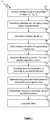
- a method for estimating the grid frequency of an electrical distribution system commences at step 102 by sampling the instantaneous voltage of three phases a, b and c of an AC electrical distribution system to generate samples V a , V b , V c representing the instantaneous voltages of the three phases at the point in time at which the samples were taken.
- a Clarke transformation is performed on the samples V a , V b , V c , to transform the samples into the ⁇ ⁇ space.
- the instantaneous voltages V a (k) , V b (k) , V c (k) at a time instant k are transformed into values ⁇ (k) and ⁇ (k).
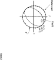
- the value z(k) of the complex variable at the time instant k is defined by the instantaneous voltages V a (k) , V b (k) , V c (k) in the complex plane.
- the generated complex variable z is input to a generating function ⁇ ( z ), and this generating function ⁇ ( z ) is integrated over the closed trajectory curve c at step 110.
- This property of the generating function ⁇ ( z ) can be used to estimate the grid frequency of the electrical distribution system from which the samples V a , V b , V c were taken, since the curve c represents one cycle period of the sampled AC system, and so the time taken for the closed-loop integral of the generating function ⁇ ( z ) along the curve c to converge to zero is the reciprocal of the grid frequency.
- any suitable generating function could be used.
- the reciprocal of the calculated convergence time is then taken, at step 114, to generate an estimate f ⁇ of the grid frequency.
- the grid frequency estimate f ⁇ can be updated every sample period, as the summation defined in equation (2) above can be performed every sample period, i.e. every kT s seconds.
- the grid frequency estimate ⁇ generated in step 114 will be susceptible to noise and sudden short lived changes arising, for example, from faults, and thus is not necessarily representative of the actual grid frequency over a longer period.
- LPF low pass filtering
- the grid frequency can be estimated quickly without needing to perform slow and computationally intensive decomposition of the AC waveforms into positive and negative waveforms. Further, experimental data shows that the method described above produces more accurate grid frequency estimates than prior art techniques.
- the system 300 may be implement in a variety of ways, for example as a plurality of separate electronic modules, in an appropriately programmed digital signal processor or as one or more software modules executing on a computer system.
- the system 300 includes a sampler 302 configured to sample the instantaneous voltage of three phases a, b, c of an AC electrical distribution system to generate samples V a , V b , V c representing the instantaneous voltages of the three phases at the sample time k .
- the sampler 302 outputs the samples V a , V b , V c to a transformation unit 304, which performs a Clarke transformation on the received samples V a , V b , V c , to transform the samples into the ⁇ space.
- An integrator unit 308 is then used to integrate the generating function ⁇ ( z ) over the closed trajectory curve c , as described above, and the time taken for the integration to converge to the predefined value is calculated by the integrator unit 308 by calculating the number of samples required for the integral to converge and multiplying this number by the sample interval, as described above. From the time taken for the integration to converge, the grid frequency estimate ⁇ is calculated by taking the reciprocal of the convergence time and output by the integrator unit 308.
- the grid frequency estimate ⁇ may be output by the integrator unit 308 to a differentiator unit 310, which is configured to differentiate the grid frequency estimate ⁇ using a dynamical system.
- the differentiator unit 310 outputs a differentiated version of the grid frequency estimate ⁇ to a low pass filter 312, which filters out high frequency components, thereby providing a refined version of the grid frequency estimate ⁇ as described above.
- the value of z ( k ) is chosen such that the method used to estimate the phase angle is sensitive only to changes in phase, and not to changes in the magnitude of the complex variable z ( k ).
- a generating function ⁇ ( z ) can be chosen to minimise the effects of noisy measurements used to generate ⁇ (k) and ⁇ ( k ).
- a contour c can be defined as the following sequence of complex numbers: c : z k , z k ⁇ 1 , ... , z k ⁇ N + 1 i.e., a unit circle with the samples spaced according to the phase estimates ⁇ ( k ) , ⁇ ( k - 1), ..., ⁇ ( k - N + 1).
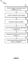
- FIG. 4 a method for estimating the grid phase angle of an electrical distribution system using the principles outlined above is shown generally at 400.
- the method 400 commences at step 402 by sampling the instantaneous voltage of three phases a, b and c of an AC electrical distribution system to generate samples V a , V b , V c representing the instantaneous voltages of the three phases at the point in time at which the samples were taken.
- a Clarke transformation is performed on the samples V a , V b , V c , to transform the samples into the ⁇ space.
- the instantaneous voltages V a (k) , V b (k) , V c (k) at time instant k are transformed into values ⁇ (k) and ⁇ (k).
- a complex variable z is generated using the values ⁇ (k) and ⁇ (k).
- the complex variable z is input into a generating function ⁇ ( z ).
- the generating function ⁇ ( z ) is integrated over the contour c defined above, and the result of this integration is added, at step 412, to a grid phase estimate ⁇ ( k - n ) for a corresponding point in a previous cycle of the electrical distribution system to generate a grid phase estimate ⁇ . If there has been no change in the phase, the grid phase estimate ⁇ will be equal to the grid phase estimate ⁇ ( k - n ), since the integral over the contour c will be equal to zero. If on the other hand the phase has changed, then the grid phase estimate ⁇ will be different from the grid phase estimate ⁇ ( k - n ). Because a new grid phase estimate ⁇ can be generated at each sample point k, any changes in the grid phase can rapidly be detected.
- the grid phase can be estimated quickly without needing to perform slow and computationally intensive decomposition of the AC waveforms into positive and negative waveforms.
- the system 500 may be implemented in a variety of ways, for example as a plurality of separate electronic modules, in an appropriately programmed digital signal processor or as one or more software modules executing on a computer system.
- the system 500 includes a sampler 502 configured to sample the instantaneous voltage of three phases a, b, c of an AC electrical distribution system to generate samples V a , V b , V c representing the instantaneous voltages of the three phases at the sample time k .
- the sampler 502 outputs the samples V a , V b , V c to a transformation unit 504, which performs a Clarke transformation on the received samples V a , V b , V c , to transform the samples into the ⁇ space.
- a complex processing unit 506 is then used to generate the complex variable z and to input the generated complex variable z to the generating function ⁇ ( z ).
- An integrator unit 508 is then used to integrate the generating function ⁇ ( z ) over the contour c, as described above, and the result of this integration is added by the integrator unit 508 to a grid phase estimate ⁇ ( k - n ) for a corresponding point in a previous cycle of the electrical distribution system to generate a grid phase estimate ⁇ which is output by the integrator unit 508.
Landscapes
- Engineering & Computer Science (AREA)
- Power Engineering (AREA)
- Physics & Mathematics (AREA)
- General Physics & Mathematics (AREA)
- Supply And Distribution Of Alternating Current (AREA)
- Measuring Phase Differences (AREA)
Priority Applications (2)
| Application Number | Priority Date | Filing Date | Title |
|---|---|---|---|
| EP18159231.2A EP3534478A1 (fr) | 2018-02-28 | 2018-02-28 | Estimation de fréquence et de phase |
| PCT/EP2019/053432 WO2019166217A1 (fr) | 2018-02-28 | 2019-02-12 | Estimation de fréquence et de phase |
Applications Claiming Priority (1)
| Application Number | Priority Date | Filing Date | Title |
|---|---|---|---|
| EP18159231.2A EP3534478A1 (fr) | 2018-02-28 | 2018-02-28 | Estimation de fréquence et de phase |
Publications (1)
| Publication Number | Publication Date |
|---|---|
| EP3534478A1 true EP3534478A1 (fr) | 2019-09-04 |
Family
ID=61526636
Family Applications (1)
| Application Number | Title | Priority Date | Filing Date |
|---|---|---|---|
| EP18159231.2A Pending EP3534478A1 (fr) | 2018-02-28 | 2018-02-28 | Estimation de fréquence et de phase |
Country Status (2)
| Country | Link |
|---|---|
| EP (1) | EP3534478A1 (fr) |
| WO (1) | WO2019166217A1 (fr) |
Cited By (1)
| Publication number | Priority date | Publication date | Assignee | Title |
|---|---|---|---|---|
| KR20210122342A (ko) * | 2020-03-30 | 2021-10-12 | 한국전력공사 | 주파수 추정 장치 및 방법 |
Citations (1)
| Publication number | Priority date | Publication date | Assignee | Title |
|---|---|---|---|---|
| US20130051498A1 (en) * | 2011-08-31 | 2013-02-28 | Cisco Technology, Inc. | Instantaneous phasor determination for poly-phase electrical grids |
-
2018
- 2018-02-28 EP EP18159231.2A patent/EP3534478A1/fr active Pending
-
2019
- 2019-02-12 WO PCT/EP2019/053432 patent/WO2019166217A1/fr not_active Ceased
Patent Citations (1)
| Publication number | Priority date | Publication date | Assignee | Title |
|---|---|---|---|---|
| US20130051498A1 (en) * | 2011-08-31 | 2013-02-28 | Cisco Technology, Inc. | Instantaneous phasor determination for poly-phase electrical grids |
Cited By (1)
| Publication number | Priority date | Publication date | Assignee | Title |
|---|---|---|---|---|
| KR20210122342A (ko) * | 2020-03-30 | 2021-10-12 | 한국전력공사 | 주파수 추정 장치 및 방법 |
Also Published As
| Publication number | Publication date |
|---|---|
| WO2019166217A1 (fr) | 2019-09-06 |
Similar Documents
| Publication | Publication Date | Title |
|---|---|---|
| US6311307B1 (en) | Digital current differential system | |
| Lavopa et al. | Real-time estimation of fundamental frequency and harmonics for active shunt power filters in aircraft electrical systems | |
| US6141196A (en) | Method and apparatus for compensation of phasor estimations | |
| Yang et al. | Multicomponent signal analysis based on polynomial chirplet transform | |
| US8108165B2 (en) | Acquiring phasors outside the frequency tracking range for power protective relays | |
| Mogharbel et al. | Least squares estimation-based synchronous generator parameter estimation using PMU data | |
| EP1852967A1 (fr) | Appareil pour le contrôle du fonctionnement à grande vitesse d'un moteur et procédé correspondant | |
| US10613127B2 (en) | Determining the frequency of an alternating signal | |
| Chen et al. | A fast-convergent modulation integral observer for online detection of the fundamental and harmonics in grid-connected power electronics systems | |
| IL268573A (en) | Method for monitoring an electromagnetic actuator device | |
| Islam et al. | Accurate estimation of phase angle for three-phase systems in presence of unbalances and distortions | |
| Marand et al. | Removal of dc offset components by using two auxiliary signals | |
| Reza et al. | Recursive DFT-based method for fast and accurate estimation of three-phase grid frequency | |
| Morello et al. | Comparison of state and parameter estimators for electric vehicle batteries | |
| CN112505391A (zh) | 一种频率自适应的交流信号有效值获取方法 | |
| WO2019166217A1 (fr) | Estimation de fréquence et de phase | |
| US11218103B2 (en) | Induction motor slip calculation | |
| CN114825372A (zh) | 一种次/超同步振荡信号的快速准确提取方法 | |
| EP3199956B1 (fr) | Appareil de détermination de la fréquence d'un signal électrique et procédé associé | |
| Serov et al. | The Method of Reducing of the Measurement Error of the Amplitude Spectrum Based on the Sliding DFT Algorithm | |
| CN102914329B (zh) | 物理量数字测量或遥测的稳态处理方法及系统 | |
| WO2021146376A1 (fr) | Appareil, procédés et support lisible par ordinateur pour des mesures efficaces en réseau électrique | |
| EP1490701B1 (fr) | Procede de controle d'un reseau electrique par determination d'un systeme equilibre inverse | |
| JP4242346B2 (ja) | 変調された信号の包絡線の決定方法 | |
| Bandak | Power systems state estimation |
Legal Events
| Date | Code | Title | Description |
|---|---|---|---|
| PUAI | Public reference made under article 153(3) epc to a published international application that has entered the european phase |
Free format text: ORIGINAL CODE: 0009012 |
|
| STAA | Information on the status of an ep patent application or granted ep patent |
Free format text: STATUS: THE APPLICATION HAS BEEN PUBLISHED |
|
| AK | Designated contracting states |
Kind code of ref document: A1 Designated state(s): AL AT BE BG CH CY CZ DE DK EE ES FI FR GB GR HR HU IE IS IT LI LT LU LV MC MK MT NL NO PL PT RO RS SE SI SK SM TR |
|
| AX | Request for extension of the european patent |
Extension state: BA ME |
|
| STAA | Information on the status of an ep patent application or granted ep patent |
Free format text: STATUS: REQUEST FOR EXAMINATION WAS MADE |
|
| 17P | Request for examination filed |
Effective date: 20200228 |
|
| RBV | Designated contracting states (corrected) |
Designated state(s): AL AT BE BG CH CY CZ DE DK EE ES FI FR GB GR HR HU IE IS IT LI LT LU LV MC MK MT NL NO PL PT RO RS SE SI SK SM TR |
|
| STAA | Information on the status of an ep patent application or granted ep patent |
Free format text: STATUS: EXAMINATION IS IN PROGRESS |
|
| 17Q | First examination report despatched |
Effective date: 20210510 |
|
| P01 | Opt-out of the competence of the unified patent court (upc) registered |
Effective date: 20230522 |
|
| RAP3 | Party data changed (applicant data changed or rights of an application transferred) |
Owner name: GE VERNOVA TECHNOLOGY GMBH |
|
| GRAP | Despatch of communication of intention to grant a patent |
Free format text: ORIGINAL CODE: EPIDOSNIGR1 |
|
| STAA | Information on the status of an ep patent application or granted ep patent |
Free format text: STATUS: GRANT OF PATENT IS INTENDED |
|
| RIC1 | Information provided on ipc code assigned before grant |
Ipc: H02J 3/00 20060101AFI20260305BHEP Ipc: G01R 19/25 20060101ALI20260305BHEP Ipc: G01R 23/02 20060101ALI20260305BHEP Ipc: G01R 25/00 20060101ALI20260305BHEP Ipc: H02J 13/12 20260101ALI20260305BHEP |
|
| INTG | Intention to grant announced |
Effective date: 20260317 |