EP3534498A1 - Procédé et dispositif de fabrication d'un stator doté d'un enroulement à bobines à air réduites - Google Patents
Procédé et dispositif de fabrication d'un stator doté d'un enroulement à bobines à air réduites Download PDFInfo
- Publication number
- EP3534498A1 EP3534498A1 EP19160494.1A EP19160494A EP3534498A1 EP 3534498 A1 EP3534498 A1 EP 3534498A1 EP 19160494 A EP19160494 A EP 19160494A EP 3534498 A1 EP3534498 A1 EP 3534498A1
- Authority
- EP
- European Patent Office
- Prior art keywords
- air
- tool part
- core
- grooves
- coils
- Prior art date
- Legal status (The legal status is an assumption and is not a legal conclusion. Google has not performed a legal analysis and makes no representation as to the accuracy of the status listed.)
- Granted
Links
Images




Classifications
-
- H—ELECTRICITY
- H02—GENERATION; CONVERSION OR DISTRIBUTION OF ELECTRIC POWER
- H02K—DYNAMO-ELECTRIC MACHINES
- H02K15/00—Processes or apparatus specially adapted for manufacturing, assembling, maintaining or repairing of dynamo-electric machines
- H02K15/06—Embedding prefabricated windings in the machines
- H02K15/062—Windings in slots; Salient pole windings
- H02K15/065—Windings consisting of complete sections, e.g. coils or waves
- H02K15/066—Windings consisting of complete sections, e.g. coils or waves inserted perpendicularly to the axis of the slots or inter-polar channels
-
- H—ELECTRICITY
- H02—GENERATION; CONVERSION OR DISTRIBUTION OF ELECTRIC POWER
- H02K—DYNAMO-ELECTRIC MACHINES
- H02K15/00—Processes or apparatus specially adapted for manufacturing, assembling, maintaining or repairing of dynamo-electric machines
- H02K15/04—Processes or apparatus specially adapted for manufacturing, assembling, maintaining or repairing of dynamo-electric machines of windings prior to their mounting into the machines
- H02K15/043—Processes or apparatus specially adapted for manufacturing, assembling, maintaining or repairing of dynamo-electric machines of windings prior to their mounting into the machines winding flat conductive wires or sheets
- H02K15/0431—Concentrated windings
-
- H—ELECTRICITY
- H02—GENERATION; CONVERSION OR DISTRIBUTION OF ELECTRIC POWER
- H02K—DYNAMO-ELECTRIC MACHINES
- H02K3/00—Details of windings
- H02K3/04—Windings characterised by the conductor shape, form or construction, e.g. with bar conductors
- H02K3/12—Windings characterised by the conductor shape, form or construction, e.g. with bar conductors arranged in slots
Definitions
- the invention relates to a method and an apparatus for producing a stator with a winding with restricted air coils.
- an apparatus and method for manufacturing a stator are disclosed.
- Previously prepared air coils are arranged in retaining grooves of a holding tool, wherein the retaining grooves are arranged on the holding tool on a circular path circumferentially.
- the holding tool is arranged in the interior of a stator core having radially inwardly open core grooves.
- the air coils are displaced radially outward from the retaining grooves on the holding tool in a direction radially in the core grooves of the stator core, and then remove the stator core with the arranged in the core slots air coils from the holding tool.
- the object of the invention is to specify a method and an apparatus for producing a stator with a winding with restricted air coils, in which the winding with the restricted air coils can be produced on a stator core in a simple and efficient manner.
- a method of manufacturing a stator having a winding with restricted air coils In this case, air coils are wound by means of a winding tool and then arranged in retaining grooves of a production tool, such that in the air coils in each case a first portion on one side of the air coil in a retaining groove of a first arrangement of retaining grooves on a first tool part and a second portion on an opposite side the air coils are arranged in a retaining groove of a second arrangement of retaining grooves on a second tool part.
- a respective set is made by the first and the second Tool part are displaced relative to each other.
- the air-core coils are displaced into the retaining grooves of the first tool part, such that, for the air-core coil, the first and second sections are respectively arranged in different ones of the retaining grooves of the first tool part.
- a stator core with core grooves is arranged, such that the core grooves are respectively arranged opposite a retaining groove of the first tool part.
- the air-core coils are displaced from the retaining grooves of the first tool part into respectively assigned core grooves. Finally, the stator core is removed with the arranged in the core grooves air coils with setback.
- an apparatus for producing a stator with a winding with restricted air coils has a winding tool which is set up to wind air-core coils.
- a production tool with a first and a second tool part wherein the production tool is arranged as follows: air coils to receive in retaining grooves, such that in the air coils in each case a first portion on one side of the air coil in a retaining groove of a first arrangement of retaining grooves a first tool part and a second portion on an opposite side of the air coil are arranged in a retaining groove of a second arrangement of retaining grooves on a second tool part; for the air coil to form a respective setting by the first and the second tool part are displaceable relative to each other; to displace the air-core coils into the retaining grooves of the first tool part such that, for the pitch-wound air coils, the first and second portions are respectively disposed in different ones of the retaining grooves of the first tool part;
- the displacement of the air-core coils with a set from the retaining grooves of the first tool part into the core grooves can be carried out with a slide element assigned per groove.
- the stator core can be formed with a laminated core.
- each coil undergoes a change of layer from a top to an underwinding. This creates a geometrically self-contained contour.
- the first portions may be disposed on the one side of the air coils in retaining grooves of a first orbiting array of retaining grooves on the first tool part, and the second portions may be on the opposite side of the air coil in retaining grooves of a second circular groove array of retaining grooves be arranged on the second tool part.
- the first circulating on a circular path arrangement of retaining grooves may be arranged radially inwardly relative to the circulating on the second circular path arrangement of retaining grooves.
- the second tool part may completely surround the first tool part in this or other embodiments.
- the air coils can be displaced in the radial direction when arranging the air coils in the retaining grooves of the production tool.
- the air coils can be arranged when arranged in the retaining grooves of the production tool by means of a movement radially inward in the retaining grooves of the first tool part.
- a displacement can be provided radially outward.
- a combination of a movement in the radial direction and a movement in the axial direction may also be provided in alternative embodiments.
- the retaining grooves of the first tool part and the retaining grooves of the second tool part can be assigned to each other in pairs in the retaining grooves of the production tool.
- the retaining grooves can be arranged in alignment in the radial direction, in particular mutually opposite groove openings, which can extend in the axial direction.
- the retaining grooves of the first tool part and the retaining grooves of the second tool part can be arranged opposite each other in the retaining grooves of the production tool substantially gap-free.
- the first tool part and the second tool part can be assembled in the production tool by means of relative displacement in the axial direction.
- a similar relative displacement may be provided when separating the first and second tool parts.
- stator core and the first tool part When arranging the stator core, the stator core and the first tool part can be displaced in the axial direction relative to each other. In this way, in one embodiment, the stator core and the first tool part can be inserted into one another by moving in the axial direction; in particular, the tool part is inserted into the stator core.
- the relative rotation of the first and second tool part leads to the cupping of the air coils, which are held with their first and second sections (coil legs) in the holding grooves of the tool parts.
- the first tool part and the second tool part can be rotated about an axis of rotation relative to each other in making the respective adjustment for the air coils.
- the width of the relative rotation can be based on the coil width in the stator core.
- the air coils with pitch can be electrically isolated in the core slots opposite the stator core.
- electrically insulating the air coils for example, insulating paper can be used.
- the electrical insulation overlaps at least partially with the surface of the air-core coil.
- the electrical insulation on the air-core coil may be formed over a region which essentially corresponds to the longitudinal extent of the core grooves of the stator core.
- the air coils may be provided with the electrical insulation prior to forming the set and inserted in the retaining grooves of the production tool with the electrical insulation.
- the electrical insulation then remains on the air coils when they are restricted and further processed.
- it may be provided to form an insulation in the retaining grooves, wherein the air coils can be processed without insulation.
- the first and / or the second portion of the air-core coil may be deformed into the core grooves after being displaced.
- the deformation of the sections of the air-core coil can be carried out by means of pressing.
- it may be provided to displace a press ram into the respective core groove for deforming, wherein the ram can be formed, for example, with the slider element, which is used to introduce the air coil into the associated core groove.
- the sections of the air-core coil in the core groove can adapt to their inner contour.
- a two-layer winding can be formed by means of the air coils with Schränkung. Also more than two windings can be provided.
- at least one respective first and one second section of different air-core coils may be arranged per core groove in order to form the layer winding.
- a radially outer layer is formed, whereupon a radially inner layer is produced, wherein in the respective layer formation identical or different steps can be provided, for example, the deformation.
- a transfer chain can be used in which the second arrangement of retaining grooves between a rectilinear arrangement and a radially circumferential arrangement is displaced.
- Nut jumps of the air coils which characterize the distance between the different core grooves, in which the sections of the air coil are arranged on the stator core, can be the same for all air coils on the stator core. Also different groove jumps can be provided on a stator core.
- the pitches of the air coils disposed on a stator core may be the same or different.
- a single-layer winding or a multilayer winding can be produced on the stator core.
- a multilayer winding for example a two-layer winding or an n-layer winding (n> 2).
- the method can be adapted such that a further tool part with its own rotary degree of freedom is provided.
- the process sequence for forming the constraints of the coils with each other is similar to the method described above.
- the method may also be designed to produce a single-layer winding.
- a winding of the externally grooved tool can then take place.
- the winding can be carried out, for example, by a rotation, a lifting and / or a pivoting method.
- the coils are not manufactured in a holding groove, but it is wound one coil side in a holding groove in each case.
- the step of setting the winding can be omitted.
- the displacement of the coils from the tool to the stator core takes place in the manner described above.
- the air coils can be manufactured in a follow-up winding process. All air coils are manufactured and assembled with a coherent winding wire.
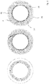
- Fig. 1 shows a schematic representation of a first tool part 1, which has a first arrangement 2 with retaining grooves 3, which are arranged circumferentially on a first circular path. Furthermore, in Fig. 1 an air coil 4 shown schematically, which has on opposite sides 5, 6 a first and a second section 7, 8. In the region of the first and the second section 7, 8, an electrical insulation 9 is formed, for example by means of insulating paper.
- an air-core coil 4 can be arranged in the retaining grooves 3, such that the air-core coil 4 is completely accommodated in the associated retaining groove 3.
- a sliding element (not shown) can be used, which moves the air-core coil 4 radially inward into the associated holding groove 3.
- Fig. 2 shows a schematic representation of an arrangement in which the first tool part 1 is arranged in a production tool 10 in a second tool part 11, such that the retaining grooves 3 of the first tool part 1 are each a holding groove 12 of the second tool part 11 are arranged opposite, so that retaining grooves itself and mutually opposite groove openings 13, 14 which extend in the axial direction in the image plane in alignment with each other.
- the retaining grooves 12 of the second tool part 11 are also arranged circumferentially along a circular path.
- the air coils 4 are displaced radially outward, such that in each case the first section 7 is arranged within the retaining groove 12 in the second tool part 11 and the second section 8 within an opposite retaining groove 3 in the first tool part 1.
- the radial displacement can be carried out with a slide element (not shown), wherein the air coils 4 in the retaining grooves 3, 12 can be displaced radially one at a time individually or in groups.
- the first tool part 1 is arranged with the arranged in the retaining air coils with offset 20 then in a stator core 30, which is formed for example with a laminated core and core grooves 31 circumferentially, such that the core grooves 31 arranged opposite the retaining grooves 3 of the first tool part 1 are.
- a stator core 30 which is formed for example with a laminated core and core grooves 31 circumferentially, such that the core grooves 31 arranged opposite the retaining grooves 3 of the first tool part 1 are.
- the air-core coils 4 are transferred or shifted with the offset 20 in the core grooves 31 of the stator core 30, so that a winding 32 is formed for the stator core 30, which, as shown in FIG Fig. 8 is formed with a radially inner layer 33 and a radially outer layer 34.
- the first and the second section 7, 8 of the air coil 4 are in this case arranged in different core grooves 31.
- a groove jump of the air-core coil 4 extends over three core grooves 31 in the embodiment shown.
- the groove jumps may be different, wherein on a stator core 31, all air coils 4 may be formed detecting the same groove jump.
- air coils 4 may be provided with different groove jumps on a stator core 31.
- Fig. 9 shows a schematic representation of a stator, the stator core 30 initially only one air coil 4 (left illustration) and then the winding 32 has (right-hand illustration), which is prepared according to the method described above. Sections 35 of the air coils 4 with a set of 20 are arranged on the front side of the stator core 30 outside the core slots.
- FIG. 10a to 10d show schematic representations in connection with a further embodiment.
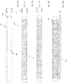
- a winding tool 40 which is formed in the embodiment shown with a rectangular cross-section and a straight longitudinal extent (strand shape), has retaining grooves 41.
- electrical insulation 9 slot insulation
- Fig. 10c the electrical insulation 9 is then closed for the respective air coils 4.
- a gate list 42 with a sliding tool is formed laterally opposite the winding tool 40, such that tool projections 43 are each associated with one of the air coils 4.
- Fig. 11a and 11b schematically show the further handling of the air coils 4.
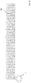
- the winding tool 40 is brought to then after the removal of a winding tool core 45 according to Fig. 11b to move the air coils 4 by means of the Gologicaliste 42 in retaining grooves 46 of the transfer chain 44.
- the transfer chain 44 is arranged on the end of the first tool part 1 with the retaining grooves 3, such that the air coil 4 in a first of the retaining grooves 41 of the transfer chain 44 in an associated one of the retaining grooves 3 on the first tool part 1 is displaced.
- the transfer chain 44 is then placed piece by piece around the first tool part 1, to move the air coils 4 respectively in the retaining grooves 3.
- the air coils 4 can be displaced with an offset 20 completely inwardly into the first tool part 1.
- the further processing of the air coils 4 can be carried out as described above in connection with the Fig. 6 ff. is explained.
- the air-core coils 4 can be completely displaced from the transfer chain 44 into the first tool part 1 prior to the formation of the offset 20 in order to then process them according to the method as described above with reference to FIG Fig. 2 to 5 was explained.
Landscapes
- Engineering & Computer Science (AREA)
- Power Engineering (AREA)
- Manufacturing & Machinery (AREA)
- Manufacture Of Motors, Generators (AREA)
Priority Applications (2)
| Application Number | Priority Date | Filing Date | Title |
|---|---|---|---|
| PL19160494T PL3534498T3 (pl) | 2018-03-02 | 2019-03-04 | Sposób i urządzenie do wytwarzania stojana z uzwojeniem o zwichrowanych cewkach powietrznych |
| SI201930087T SI3534498T1 (sl) | 2018-03-02 | 2019-03-04 | Postopek in naprava za izdelavo statorja z navitjem z zamaknjenimi zračnimi tuljavami |
Applications Claiming Priority (1)
| Application Number | Priority Date | Filing Date | Title |
|---|---|---|---|
| DE102018104838.6A DE102018104838A1 (de) | 2018-03-02 | 2018-03-02 | Verfahren und Vorrichtung zum Herstellen eines Stators mit einer Wicklung mit geschränkten Luftspulen |
Publications (2)
| Publication Number | Publication Date |
|---|---|
| EP3534498A1 true EP3534498A1 (fr) | 2019-09-04 |
| EP3534498B1 EP3534498B1 (fr) | 2021-05-26 |
Family
ID=65685234
Family Applications (1)
| Application Number | Title | Priority Date | Filing Date |
|---|---|---|---|
| EP19160494.1A Active EP3534498B1 (fr) | 2018-03-02 | 2019-03-04 | Procédé et dispositif de fabrication d'un stator doté d'un enroulement à bobines à air réduites |
Country Status (6)
| Country | Link |
|---|---|
| EP (1) | EP3534498B1 (fr) |
| DE (1) | DE102018104838A1 (fr) |
| ES (1) | ES2887699T3 (fr) |
| HU (1) | HUE055123T2 (fr) |
| PL (1) | PL3534498T3 (fr) |
| SI (1) | SI3534498T1 (fr) |
Cited By (4)
| Publication number | Priority date | Publication date | Assignee | Title |
|---|---|---|---|---|
| DE102021200844A1 (de) | 2021-01-29 | 2022-08-04 | Siemens Mobility GmbH | Verfahren zum Formen und Einbringen von Spulen in einen Stator einer elektrischen rotierenden Maschine |
| DE102021200843A1 (de) | 2021-01-29 | 2022-08-04 | Siemens Mobility GmbH | Verfahren zum Einbringen und Formen von Spulen in einen Stator einer elektrischen rotierenden Maschine |
| DE102021200839A1 (de) | 2021-01-29 | 2022-08-04 | Siemens Mobility GmbH | Verfahren zum Formen und Einbringen von Spulen in einen Stator einer elektrischen rotierenden Maschine |
| DE102021200841A1 (de) | 2021-01-29 | 2022-08-04 | Siemens Mobility GmbH | Verfahren zum Formen und Einbringen von Spulen in einen Stator einer elektrischen rotierenden Maschine |
Families Citing this family (2)
| Publication number | Priority date | Publication date | Assignee | Title |
|---|---|---|---|---|
| DE102021125493A1 (de) | 2021-10-01 | 2023-04-06 | Bayerische Motoren Werke Aktiengesellschaft | Verfahren zum Herstellen einer Formspulenwicklung, Stator sowie Werkzeug zum Herstellen von Formspulenwicklungen |
| DE102022105057A1 (de) | 2022-03-03 | 2023-09-07 | Schaeffler Technologies AG & Co. KG | Verfahren zum Einbringen einer Isolierung in die Nuten eines Einziehwerkzeuges |
Citations (5)
| Publication number | Priority date | Publication date | Assignee | Title |
|---|---|---|---|---|
| EP1940006A2 (fr) * | 2006-12-28 | 2008-07-02 | Hitachi, Ltd. | Machine élecrique pour véhicule |
| US20080201935A1 (en) * | 2007-02-26 | 2008-08-28 | Hitachi, Ltd. | Manufacturing Method for Rotary Electric Machine and Stator |
| US20110043059A1 (en) * | 2006-12-29 | 2011-02-24 | Gert Wolf | Alternating current generator comprising a stator and a stator winding inserted in stator grooves made of winding elements and method for producing an inventive stator |
| EP2647110A2 (fr) * | 2010-12-01 | 2013-10-09 | Robert Bosch GmbH | Procédé de fabrication d'un enroulement de stator d'un moteur électrique, notamment d'un générateur de courant alternatif |
| DE112016000469T5 (de) | 2015-03-02 | 2017-10-05 | Nittoku Engineering Co., Ltd. | Stator-herstellungs-gerät und stator-herstellungs-verfahren |
Family Cites Families (5)
| Publication number | Priority date | Publication date | Assignee | Title |
|---|---|---|---|---|
| JP2009011116A (ja) * | 2007-06-29 | 2009-01-15 | Hitachi Ltd | 渡り導体部がクランク形状の波巻きコイルを備えた回転電機、分布巻固定子並びにそれらの成形方法及び成形装置 |
| DE102009024230A1 (de) * | 2009-05-29 | 2010-12-02 | Robert Bosch Gmbh | Verfahren zur Herstellung einer Ständerwicklung einer elektrischen Maschine, insbesondere zur Herstellung eines Wechselstromgenerators |
| DE102009024231A1 (de) * | 2009-05-29 | 2010-12-09 | Robert Bosch Gmbh | Verfahren zur Herstellung einer Ständerwicklung einer elektrischen Maschine, insbesondere eines Wechselstromgenerators |
| JP2013118764A (ja) * | 2011-12-02 | 2013-06-13 | Aisin Aw Co Ltd | ステータ製造方法及びステータ製造装置 |
| DE102016212382A1 (de) * | 2016-07-07 | 2018-01-11 | Zf Friedrichshafen Ag | Verfahren und Adapter zum Wickeln eines Spulenkorbs |
-
2018
- 2018-03-02 DE DE102018104838.6A patent/DE102018104838A1/de not_active Withdrawn
-
2019
- 2019-03-04 HU HUE19160494A patent/HUE055123T2/hu unknown
- 2019-03-04 ES ES19160494T patent/ES2887699T3/es active Active
- 2019-03-04 SI SI201930087T patent/SI3534498T1/sl unknown
- 2019-03-04 PL PL19160494T patent/PL3534498T3/pl unknown
- 2019-03-04 EP EP19160494.1A patent/EP3534498B1/fr active Active
Patent Citations (5)
| Publication number | Priority date | Publication date | Assignee | Title |
|---|---|---|---|---|
| EP1940006A2 (fr) * | 2006-12-28 | 2008-07-02 | Hitachi, Ltd. | Machine élecrique pour véhicule |
| US20110043059A1 (en) * | 2006-12-29 | 2011-02-24 | Gert Wolf | Alternating current generator comprising a stator and a stator winding inserted in stator grooves made of winding elements and method for producing an inventive stator |
| US20080201935A1 (en) * | 2007-02-26 | 2008-08-28 | Hitachi, Ltd. | Manufacturing Method for Rotary Electric Machine and Stator |
| EP2647110A2 (fr) * | 2010-12-01 | 2013-10-09 | Robert Bosch GmbH | Procédé de fabrication d'un enroulement de stator d'un moteur électrique, notamment d'un générateur de courant alternatif |
| DE112016000469T5 (de) | 2015-03-02 | 2017-10-05 | Nittoku Engineering Co., Ltd. | Stator-herstellungs-gerät und stator-herstellungs-verfahren |
Cited By (4)
| Publication number | Priority date | Publication date | Assignee | Title |
|---|---|---|---|---|
| DE102021200844A1 (de) | 2021-01-29 | 2022-08-04 | Siemens Mobility GmbH | Verfahren zum Formen und Einbringen von Spulen in einen Stator einer elektrischen rotierenden Maschine |
| DE102021200843A1 (de) | 2021-01-29 | 2022-08-04 | Siemens Mobility GmbH | Verfahren zum Einbringen und Formen von Spulen in einen Stator einer elektrischen rotierenden Maschine |
| DE102021200839A1 (de) | 2021-01-29 | 2022-08-04 | Siemens Mobility GmbH | Verfahren zum Formen und Einbringen von Spulen in einen Stator einer elektrischen rotierenden Maschine |
| DE102021200841A1 (de) | 2021-01-29 | 2022-08-04 | Siemens Mobility GmbH | Verfahren zum Formen und Einbringen von Spulen in einen Stator einer elektrischen rotierenden Maschine |
Also Published As
| Publication number | Publication date |
|---|---|
| ES2887699T3 (es) | 2021-12-27 |
| HUE055123T2 (hu) | 2021-11-29 |
| SI3534498T1 (sl) | 2021-11-30 |
| DE102018104838A1 (de) | 2019-09-05 |
| EP3534498B1 (fr) | 2021-05-26 |
| PL3534498T3 (pl) | 2021-11-29 |
Similar Documents
| Publication | Publication Date | Title |
|---|---|---|
| EP3381108B1 (fr) | Procédé de fabrication d'un enroulement de bobine à déposer dans des gorges radialement ouvertes de stators et de rotors de machines électriques | |
| EP3534498A1 (fr) | Procédé et dispositif de fabrication d'un stator doté d'un enroulement à bobines à air réduites | |
| EP3718199B1 (fr) | Méthode de fabrication d'un sous-ensemble d'un stator et dispositif de fabrication dudit sous-ensemble | |
| DE102015217922A1 (de) | Verfahren und zweiteilige Werkzeuganordnung zum Herstellen eines Stators für eine elektrische Maschine | |
| DE10018140A1 (de) | Stator für eine rotierende elektrische Maschine und Verfahren zu seiner Herstellung | |
| AT520311B1 (de) | Verfahren und Vorrichtung zur automatisierten Herstellung eines Stators einer elektrischen Maschine | |
| DE102016203167A1 (de) | Vorrichtung und Verfahren zum Herstellen eines wellenförmig gebogenen Drahtsegments | |
| DE102019211713A1 (de) | Twistvorrichtung sowie Verfahren für eine Hairpin-Wicklung | |
| EP1905146A1 (fr) | Procede pour produire un enroulement d'une machine electrique | |
| DE102014003602A1 (de) | Verfahren zum Herstellen einer Wicklung | |
| DE102018206003A1 (de) | Vorrichtung und Verfahren zur Ausrichtung einer Hairpinwicklung | |
| EP3654502B1 (fr) | Procédé et dispositif de fabrication d'un agencement doté d'un support d'enroulement rainuré et un enroulement de bobine pour une machine électrique | |
| WO2018065318A1 (fr) | Dispositif de montage permettant l'introduction simultanée de barres de cuivre | |
| EP3991281A1 (fr) | Procédé de fabrication d'un stator destiné à une machine électrique | |
| EP4026232B1 (fr) | Bobine avec bobinage en épingle et procédé pour sa fabrication | |
| WO2016005076A1 (fr) | Procédé de fabrication d'une machine électrique comportant des bobines formées et machine électrique et outil de fabrication | |
| DE102019220173A1 (de) | Verfahren zum Biegeverdrehen von Kupferstäben | |
| EP4496195A1 (fr) | Procédé de fabrication d'un stator pour une machine électrique et machine électrique | |
| DE102022129444A1 (de) | Verfahren zur Montage eines Stators mit einer Wellenwicklung | |
| EP3507892B1 (fr) | Dispositif de montage pour introduire simultanément des barres de cuivre dans une machine électrique et procédé associé | |
| DE102024132530A1 (de) | Steckspulenanordnung, Stator und Verfahren sowie Werkzeug für das Bearbeiten einer Steckspulenanordnung eines Stators eines elektromechanischen Wandlers | |
| DE102023207763A1 (de) | Werkzeug und Verfahren zum Separieren und Ausrichten von mehreren parallel angeordneten Drähten | |
| DE102024209924A1 (de) | Vorrichtung und Verfahren zum Herstellen von wellenförmig angeordneten Drahtsegmenten in einem Drahtabschnitt | |
| WO2023134808A1 (fr) | Dispositif d'alignement des segments d'un anneau de stator, procédé d'alignement des segments d'un anneau de stator et procédé d'installation d'un anneau de stator | |
| DE102022101619A1 (de) | Verfahren zur Umformung einer Wellenwicklung und eine nach dem Verfahren umgeformte Wellenwicklung |
Legal Events
| Date | Code | Title | Description |
|---|---|---|---|
| PUAI | Public reference made under article 153(3) epc to a published international application that has entered the european phase |
Free format text: ORIGINAL CODE: 0009012 |
|
| STAA | Information on the status of an ep patent application or granted ep patent |
Free format text: STATUS: THE APPLICATION HAS BEEN PUBLISHED |
|
| AK | Designated contracting states |
Kind code of ref document: A1 Designated state(s): AL AT BE BG CH CY CZ DE DK EE ES FI FR GB GR HR HU IE IS IT LI LT LU LV MC MK MT NL NO PL PT RO RS SE SI SK SM TR |
|
| AX | Request for extension of the european patent |
Extension state: BA ME |
|
| STAA | Information on the status of an ep patent application or granted ep patent |
Free format text: STATUS: REQUEST FOR EXAMINATION WAS MADE |
|
| 17P | Request for examination filed |
Effective date: 20200304 |
|
| RBV | Designated contracting states (corrected) |
Designated state(s): AL AT BE BG CH CY CZ DE DK EE ES FI FR GB GR HR HU IE IS IT LI LT LU LV MC MK MT NL NO PL PT RO RS SE SI SK SM TR |
|
| GRAP | Despatch of communication of intention to grant a patent |
Free format text: ORIGINAL CODE: EPIDOSNIGR1 |
|
| STAA | Information on the status of an ep patent application or granted ep patent |
Free format text: STATUS: GRANT OF PATENT IS INTENDED |
|
| INTG | Intention to grant announced |
Effective date: 20201223 |
|
| GRAS | Grant fee paid |
Free format text: ORIGINAL CODE: EPIDOSNIGR3 |
|
| GRAA | (expected) grant |
Free format text: ORIGINAL CODE: 0009210 |
|
| STAA | Information on the status of an ep patent application or granted ep patent |
Free format text: STATUS: THE PATENT HAS BEEN GRANTED |
|
| AK | Designated contracting states |
Kind code of ref document: B1 Designated state(s): AL AT BE BG CH CY CZ DE DK EE ES FI FR GB GR HR HU IE IS IT LI LT LU LV MC MK MT NL NO PL PT RO RS SE SI SK SM TR |
|
| REG | Reference to a national code |
Ref country code: GB Ref legal event code: FG4D Free format text: NOT ENGLISH |
|
| REG | Reference to a national code |
Ref country code: CH Ref legal event code: EP |
|
| REG | Reference to a national code |
Ref country code: AT Ref legal event code: REF Ref document number: 1397221 Country of ref document: AT Kind code of ref document: T Effective date: 20210615 |
|
| REG | Reference to a national code |
Ref country code: DE Ref legal event code: R096 Ref document number: 502019001469 Country of ref document: DE |
|
| REG | Reference to a national code |
Ref country code: IE Ref legal event code: FG4D Free format text: LANGUAGE OF EP DOCUMENT: GERMAN |
|
| REG | Reference to a national code |
Ref country code: RO Ref legal event code: EPE |
|
| REG | Reference to a national code |
Ref country code: SE Ref legal event code: TRGR |
|
| REG | Reference to a national code |
Ref country code: LT Ref legal event code: MG9D |
|
| REG | Reference to a national code |
Ref country code: SK Ref legal event code: T3 Ref document number: E 38002 Country of ref document: SK |
|
| PG25 | Lapsed in a contracting state [announced via postgrant information from national office to epo] |
Ref country code: BG Free format text: LAPSE BECAUSE OF FAILURE TO SUBMIT A TRANSLATION OF THE DESCRIPTION OR TO PAY THE FEE WITHIN THE PRESCRIBED TIME-LIMIT Effective date: 20210826 Ref country code: FI Free format text: LAPSE BECAUSE OF FAILURE TO SUBMIT A TRANSLATION OF THE DESCRIPTION OR TO PAY THE FEE WITHIN THE PRESCRIBED TIME-LIMIT Effective date: 20210526 Ref country code: HR Free format text: LAPSE BECAUSE OF FAILURE TO SUBMIT A TRANSLATION OF THE DESCRIPTION OR TO PAY THE FEE WITHIN THE PRESCRIBED TIME-LIMIT Effective date: 20210526 Ref country code: LT Free format text: LAPSE BECAUSE OF FAILURE TO SUBMIT A TRANSLATION OF THE DESCRIPTION OR TO PAY THE FEE WITHIN THE PRESCRIBED TIME-LIMIT Effective date: 20210526 |
|
| REG | Reference to a national code |
Ref country code: NL Ref legal event code: MP Effective date: 20210526 |
|
| REG | Reference to a national code |
Ref country code: HU Ref legal event code: AG4A Ref document number: E055123 Country of ref document: HU |
|
| PG25 | Lapsed in a contracting state [announced via postgrant information from national office to epo] |
Ref country code: LV Free format text: LAPSE BECAUSE OF FAILURE TO SUBMIT A TRANSLATION OF THE DESCRIPTION OR TO PAY THE FEE WITHIN THE PRESCRIBED TIME-LIMIT Effective date: 20210526 Ref country code: NO Free format text: LAPSE BECAUSE OF FAILURE TO SUBMIT A TRANSLATION OF THE DESCRIPTION OR TO PAY THE FEE WITHIN THE PRESCRIBED TIME-LIMIT Effective date: 20210826 Ref country code: RS Free format text: LAPSE BECAUSE OF FAILURE TO SUBMIT A TRANSLATION OF THE DESCRIPTION OR TO PAY THE FEE WITHIN THE PRESCRIBED TIME-LIMIT Effective date: 20210526 Ref country code: PT Free format text: LAPSE BECAUSE OF FAILURE TO SUBMIT A TRANSLATION OF THE DESCRIPTION OR TO PAY THE FEE WITHIN THE PRESCRIBED TIME-LIMIT Effective date: 20210927 Ref country code: IS Free format text: LAPSE BECAUSE OF FAILURE TO SUBMIT A TRANSLATION OF THE DESCRIPTION OR TO PAY THE FEE WITHIN THE PRESCRIBED TIME-LIMIT Effective date: 20210926 Ref country code: GR Free format text: LAPSE BECAUSE OF FAILURE TO SUBMIT A TRANSLATION OF THE DESCRIPTION OR TO PAY THE FEE WITHIN THE PRESCRIBED TIME-LIMIT Effective date: 20210827 |
|
| REG | Reference to a national code |
Ref country code: ES Ref legal event code: FG2A Ref document number: 2887699 Country of ref document: ES Kind code of ref document: T3 Effective date: 20211227 |
|
| PG25 | Lapsed in a contracting state [announced via postgrant information from national office to epo] |
Ref country code: NL Free format text: LAPSE BECAUSE OF FAILURE TO SUBMIT A TRANSLATION OF THE DESCRIPTION OR TO PAY THE FEE WITHIN THE PRESCRIBED TIME-LIMIT Effective date: 20210526 |
|
| PG25 | Lapsed in a contracting state [announced via postgrant information from national office to epo] |
Ref country code: EE Free format text: LAPSE BECAUSE OF FAILURE TO SUBMIT A TRANSLATION OF THE DESCRIPTION OR TO PAY THE FEE WITHIN THE PRESCRIBED TIME-LIMIT Effective date: 20210526 Ref country code: CZ Free format text: LAPSE BECAUSE OF FAILURE TO SUBMIT A TRANSLATION OF THE DESCRIPTION OR TO PAY THE FEE WITHIN THE PRESCRIBED TIME-LIMIT Effective date: 20210526 Ref country code: DK Free format text: LAPSE BECAUSE OF FAILURE TO SUBMIT A TRANSLATION OF THE DESCRIPTION OR TO PAY THE FEE WITHIN THE PRESCRIBED TIME-LIMIT Effective date: 20210526 Ref country code: SM Free format text: LAPSE BECAUSE OF FAILURE TO SUBMIT A TRANSLATION OF THE DESCRIPTION OR TO PAY THE FEE WITHIN THE PRESCRIBED TIME-LIMIT Effective date: 20210526 |
|
| REG | Reference to a national code |
Ref country code: DE Ref legal event code: R097 Ref document number: 502019001469 Country of ref document: DE |
|
| PLBE | No opposition filed within time limit |
Free format text: ORIGINAL CODE: 0009261 |
|
| STAA | Information on the status of an ep patent application or granted ep patent |
Free format text: STATUS: NO OPPOSITION FILED WITHIN TIME LIMIT |
|
| 26N | No opposition filed |
Effective date: 20220301 |
|
| PG25 | Lapsed in a contracting state [announced via postgrant information from national office to epo] |
Ref country code: IS Free format text: LAPSE BECAUSE OF FAILURE TO SUBMIT A TRANSLATION OF THE DESCRIPTION OR TO PAY THE FEE WITHIN THE PRESCRIBED TIME-LIMIT Effective date: 20210926 Ref country code: AL Free format text: LAPSE BECAUSE OF FAILURE TO SUBMIT A TRANSLATION OF THE DESCRIPTION OR TO PAY THE FEE WITHIN THE PRESCRIBED TIME-LIMIT Effective date: 20210526 |
|
| PG25 | Lapsed in a contracting state [announced via postgrant information from national office to epo] |
Ref country code: MC Free format text: LAPSE BECAUSE OF FAILURE TO SUBMIT A TRANSLATION OF THE DESCRIPTION OR TO PAY THE FEE WITHIN THE PRESCRIBED TIME-LIMIT Effective date: 20210526 |
|
| REG | Reference to a national code |
Ref country code: CH Ref legal event code: PL |
|
| REG | Reference to a national code |
Ref country code: BE Ref legal event code: MM Effective date: 20220331 |
|
| PG25 | Lapsed in a contracting state [announced via postgrant information from national office to epo] |
Ref country code: LU Free format text: LAPSE BECAUSE OF NON-PAYMENT OF DUE FEES Effective date: 20220304 Ref country code: LI Free format text: LAPSE BECAUSE OF NON-PAYMENT OF DUE FEES Effective date: 20220331 Ref country code: IE Free format text: LAPSE BECAUSE OF NON-PAYMENT OF DUE FEES Effective date: 20220304 Ref country code: CH Free format text: LAPSE BECAUSE OF NON-PAYMENT OF DUE FEES Effective date: 20220331 |
|
| PG25 | Lapsed in a contracting state [announced via postgrant information from national office to epo] |
Ref country code: BE Free format text: LAPSE BECAUSE OF NON-PAYMENT OF DUE FEES Effective date: 20220331 |
|
| PG25 | Lapsed in a contracting state [announced via postgrant information from national office to epo] |
Ref country code: MK Free format text: LAPSE BECAUSE OF FAILURE TO SUBMIT A TRANSLATION OF THE DESCRIPTION OR TO PAY THE FEE WITHIN THE PRESCRIBED TIME-LIMIT Effective date: 20210526 Ref country code: CY Free format text: LAPSE BECAUSE OF FAILURE TO SUBMIT A TRANSLATION OF THE DESCRIPTION OR TO PAY THE FEE WITHIN THE PRESCRIBED TIME-LIMIT Effective date: 20210526 |
|
| PG25 | Lapsed in a contracting state [announced via postgrant information from national office to epo] |
Ref country code: MT Free format text: LAPSE BECAUSE OF FAILURE TO SUBMIT A TRANSLATION OF THE DESCRIPTION OR TO PAY THE FEE WITHIN THE PRESCRIBED TIME-LIMIT Effective date: 20210526 |
|
| PGFP | Annual fee paid to national office [announced via postgrant information from national office to epo] |
Ref country code: SI Payment date: 20250220 Year of fee payment: 7 |
|
| REG | Reference to a national code |
Ref country code: AT Ref legal event code: MM01 Ref document number: 1397221 Country of ref document: AT Kind code of ref document: T Effective date: 20240304 |
|
| PGFP | Annual fee paid to national office [announced via postgrant information from national office to epo] |
Ref country code: ES Payment date: 20250429 Year of fee payment: 7 |
|
| PG25 | Lapsed in a contracting state [announced via postgrant information from national office to epo] |
Ref country code: AT Free format text: LAPSE BECAUSE OF NON-PAYMENT OF DUE FEES Effective date: 20240304 |
|
| PG25 | Lapsed in a contracting state [announced via postgrant information from national office to epo] |
Ref country code: TR Free format text: LAPSE BECAUSE OF FAILURE TO SUBMIT A TRANSLATION OF THE DESCRIPTION OR TO PAY THE FEE WITHIN THE PRESCRIBED TIME-LIMIT Effective date: 20210526 |
|
| PGFP | Annual fee paid to national office [announced via postgrant information from national office to epo] |
Ref country code: SE Payment date: 20260319 Year of fee payment: 8 |
|
| PGFP | Annual fee paid to national office [announced via postgrant information from national office to epo] |
Ref country code: GB Payment date: 20260324 Year of fee payment: 8 |
|
| PGFP | Annual fee paid to national office [announced via postgrant information from national office to epo] |
Ref country code: DE Payment date: 20260319 Year of fee payment: 8 |
|
| PGFP | Annual fee paid to national office [announced via postgrant information from national office to epo] |
Ref country code: AT Payment date: 20260410 Year of fee payment: 5 |
|
| PGFP | Annual fee paid to national office [announced via postgrant information from national office to epo] |
Ref country code: RO Payment date: 20260316 Year of fee payment: 8 Ref country code: IT Payment date: 20260324 Year of fee payment: 8 |
|
| PGFP | Annual fee paid to national office [announced via postgrant information from national office to epo] |
Ref country code: HU Payment date: 20260323 Year of fee payment: 8 |
|
| PGFP | Annual fee paid to national office [announced via postgrant information from national office to epo] |
Ref country code: FR Payment date: 20260320 Year of fee payment: 8 |
|
| PGFP | Annual fee paid to national office [announced via postgrant information from national office to epo] |
Ref country code: PL Payment date: 20260313 Year of fee payment: 8 |
|
| PGFP | Annual fee paid to national office [announced via postgrant information from national office to epo] |
Ref country code: SK Payment date: 20260317 Year of fee payment: 8 |