EP3534675B1 - System und verfahren zum zonenkochen nach spektrometrischer theorie in einer elektromagnetischen kochvorrichtung - Google Patents
System und verfahren zum zonenkochen nach spektrometrischer theorie in einer elektromagnetischen kochvorrichtung Download PDFInfo
- Publication number
- EP3534675B1 EP3534675B1 EP19159444.9A EP19159444A EP3534675B1 EP 3534675 B1 EP3534675 B1 EP 3534675B1 EP 19159444 A EP19159444 A EP 19159444A EP 3534675 B1 EP3534675 B1 EP 3534675B1
- Authority
- EP
- European Patent Office
- Prior art keywords
- controller
- power
- cavity
- efficiency
- feeds
- Prior art date
- Legal status (The legal status is an assumption and is not a legal conclusion. Google has not performed a legal analysis and makes no representation as to the accuracy of the status listed.)
- Not-in-force
Links
Images



















Classifications
-
- H—ELECTRICITY
- H05—ELECTRIC TECHNIQUES NOT OTHERWISE PROVIDED FOR
- H05B—ELECTRIC HEATING; ELECTRIC LIGHT SOURCES NOT OTHERWISE PROVIDED FOR; CIRCUIT ARRANGEMENTS FOR ELECTRIC LIGHT SOURCES, IN GENERAL
- H05B6/00—Heating by electric, magnetic or electromagnetic fields
- H05B6/64—Heating using microwaves
- H05B6/66—Circuits
- H05B6/68—Circuits for monitoring or control
- H05B6/686—Circuits comprising a signal generator and power amplifier, e.g. using solid state oscillators
-
- H—ELECTRICITY
- H05—ELECTRIC TECHNIQUES NOT OTHERWISE PROVIDED FOR
- H05B—ELECTRIC HEATING; ELECTRIC LIGHT SOURCES NOT OTHERWISE PROVIDED FOR; CIRCUIT ARRANGEMENTS FOR ELECTRIC LIGHT SOURCES, IN GENERAL
- H05B6/00—Heating by electric, magnetic or electromagnetic fields
- H05B6/46—Dielectric heating
- H05B6/48—Circuits
- H05B6/50—Circuits for monitoring or control
-
- H—ELECTRICITY
- H05—ELECTRIC TECHNIQUES NOT OTHERWISE PROVIDED FOR
- H05B—ELECTRIC HEATING; ELECTRIC LIGHT SOURCES NOT OTHERWISE PROVIDED FOR; CIRCUIT ARRANGEMENTS FOR ELECTRIC LIGHT SOURCES, IN GENERAL
- H05B6/00—Heating by electric, magnetic or electromagnetic fields
- H05B6/46—Dielectric heating
- H05B6/52—Feed lines
-
- H—ELECTRICITY
- H05—ELECTRIC TECHNIQUES NOT OTHERWISE PROVIDED FOR
- H05B—ELECTRIC HEATING; ELECTRIC LIGHT SOURCES NOT OTHERWISE PROVIDED FOR; CIRCUIT ARRANGEMENTS FOR ELECTRIC LIGHT SOURCES, IN GENERAL
- H05B6/00—Heating by electric, magnetic or electromagnetic fields
- H05B6/64—Heating using microwaves
- H05B6/6447—Method of operation or details of the microwave heating apparatus related to the use of detectors or sensors
- H05B6/645—Method of operation or details of the microwave heating apparatus related to the use of detectors or sensors using temperature sensors
-
- H—ELECTRICITY
- H05—ELECTRIC TECHNIQUES NOT OTHERWISE PROVIDED FOR
- H05B—ELECTRIC HEATING; ELECTRIC LIGHT SOURCES NOT OTHERWISE PROVIDED FOR; CIRCUIT ARRANGEMENTS FOR ELECTRIC LIGHT SOURCES, IN GENERAL
- H05B6/00—Heating by electric, magnetic or electromagnetic fields
- H05B6/64—Heating using microwaves
- H05B6/66—Circuits
- H05B6/664—Aspects related to the power supply of the microwave heating apparatus
-
- H—ELECTRICITY
- H05—ELECTRIC TECHNIQUES NOT OTHERWISE PROVIDED FOR
- H05B—ELECTRIC HEATING; ELECTRIC LIGHT SOURCES NOT OTHERWISE PROVIDED FOR; CIRCUIT ARRANGEMENTS FOR ELECTRIC LIGHT SOURCES, IN GENERAL
- H05B6/00—Heating by electric, magnetic or electromagnetic fields
- H05B6/64—Heating using microwaves
- H05B6/66—Circuits
- H05B6/68—Circuits for monitoring or control
- H05B6/687—Circuits for monitoring or control for cooking
-
- H—ELECTRICITY
- H05—ELECTRIC TECHNIQUES NOT OTHERWISE PROVIDED FOR
- H05B—ELECTRIC HEATING; ELECTRIC LIGHT SOURCES NOT OTHERWISE PROVIDED FOR; CIRCUIT ARRANGEMENTS FOR ELECTRIC LIGHT SOURCES, IN GENERAL
- H05B6/00—Heating by electric, magnetic or electromagnetic fields
- H05B6/64—Heating using microwaves
- H05B6/70—Feed lines
- H05B6/705—Feed lines using microwave tuning
-
- H—ELECTRICITY
- H05—ELECTRIC TECHNIQUES NOT OTHERWISE PROVIDED FOR
- H05B—ELECTRIC HEATING; ELECTRIC LIGHT SOURCES NOT OTHERWISE PROVIDED FOR; CIRCUIT ARRANGEMENTS FOR ELECTRIC LIGHT SOURCES, IN GENERAL
- H05B6/00—Heating by electric, magnetic or electromagnetic fields
- H05B6/64—Heating using microwaves
- H05B6/70—Feed lines
- H05B6/707—Feed lines using waveguides
-
- H—ELECTRICITY
- H05—ELECTRIC TECHNIQUES NOT OTHERWISE PROVIDED FOR
- H05B—ELECTRIC HEATING; ELECTRIC LIGHT SOURCES NOT OTHERWISE PROVIDED FOR; CIRCUIT ARRANGEMENTS FOR ELECTRIC LIGHT SOURCES, IN GENERAL
- H05B6/00—Heating by electric, magnetic or electromagnetic fields
- H05B6/64—Heating using microwaves
- H05B6/74—Mode transformers or mode stirrers
- H05B6/745—Rotatable stirrers
-
- Y—GENERAL TAGGING OF NEW TECHNOLOGICAL DEVELOPMENTS; GENERAL TAGGING OF CROSS-SECTIONAL TECHNOLOGIES SPANNING OVER SEVERAL SECTIONS OF THE IPC; TECHNICAL SUBJECTS COVERED BY FORMER USPC CROSS-REFERENCE ART COLLECTIONS [XRACs] AND DIGESTS
- Y02—TECHNOLOGIES OR APPLICATIONS FOR MITIGATION OR ADAPTATION AGAINST CLIMATE CHANGE
- Y02B—CLIMATE CHANGE MITIGATION TECHNOLOGIES RELATED TO BUILDINGS, e.g. HOUSING, HOUSE APPLIANCES OR RELATED END-USER APPLICATIONS
- Y02B40/00—Technologies aiming at improving the efficiency of home appliances, e.g. induction cooking or efficient technologies for refrigerators, freezers or dish washers
Definitions
- the guiding structure 102 can include a microstrip that is printed on a laminate 122.
- the laminate 122 is a dielectric substrate that can include any material suitable for the provision of insulating layers of a printed circuit board including, but not limited to, FR-2 material or FR-4 material.
- the laminate 122 is positioned on the metal base plate 120 that provides mechanical support to the circulator 104. Additionally, the metal base plate 120 acts as a thermal dissipating mass and to spread heat generated by the circulator 104.
- the metal base plate 120 includes a pocket 124 to house the lower ferrite magnet 128.
- the RF signal generator (cf. element 16 in FIG. 1 ) can rely on feedback in the form of signals indicative of the forward and backward power levels or the relative phases of the radio frequency signals conveyed to the enclosed cavity (cf. element 20 in FIG. 1 ). Therefore, in addition to the amplifying components for outputting a radio frequency signal that is amplified in power with respect to an input radio frequency signal, conventional high-power amplifiers can include a measuring component that outputs a signal indicative of the radio frequency power transmitted and received by the amplifying component.
- the reflectometer 164 can include any components useful for measuring the phase of a radio frequency signal including, but not limited to, a directional coupler containing matched calibrated detectors or a pair of single-detector couplers oriented so as to measure the electrical power flowing in both directions within the waveguide 110.
- the integrated measurement system 160 can characterize the radio frequency transmissions according to power and phase and can be used to form a networked description as embodied in the scattering matrix or S-parameters.
- the reflectometer 164 is a six port reflectometer configured to measure the phase of the forward and backward radio frequency radiation within the waveguide.
- step 614 the controller 14 may continue to step 616 to compare the absolute value of the power difference
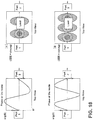
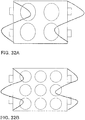
- FIGS. 13A and 13B a schematic diagram illustrating features of a method to locate and classify foodstuff 300A,B positioned within a resonant cavity 222 in accordance with various aspects described herein is shown.
- the electromagnetic cooking device can generate a heating pattern 360A in the cavity 222 with an even symmetry where the maximum heating contours 302 do not occur in the center of the cavity 222.
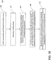
- the method includes the steps of selecting a heating target corresponding to an amount of energy that is to be to delivered to each symmetry plane in the enclosed cavity 20, 222 based in part upon a load positioned in the enclosed cavity 20, 222 (step 402); detecting asymmetries and find the optimal rotation plane (step 404); generating a heating strategy based on the heating target to determine desired heating patterns, the heating strategy having a selected sequence of resonant modes to be excited in the enclosed cavity 20, 222 that correspond to the desired heating patterns (step 406); exciting the enclosed cavity 20, 222 with a selected set of phasors for a set of frequencies corresponding to each resonant mode of the selected sequence of resonant modes (step 408) to create heating patterns; and monitoring the created heating patterns based on the forward and backward power measurements at the RF feeds 26A-26D, 226A-226B to use closed-loop regulation to selectively modify the sequence of resonant modes into the enclosed cavity 20, 222 based on the desired heating patterns and the created heating patterns
- the controller 14 After having selected a nominal phasor, it is possible to identify a set of excitations for each resonant mode to be analyzed, by acting on the phase-shifts and keeping the frequency locked for that resonant mode. Specifically, for each unrotated resonant mode, the controller 14 generates a set of excitations with the same frequency (of the nominal mode) and a combination of phase-shifts.
- the set of phases might be defined a-priori, statically defined on run-time, or even be adaptive according to different parameters.
- the phase-axis might include all the phase-shifts inside the analysis range or a few samples only, in order to save computational time at the expense of approximation.
- the phase-shifts are not arbitrarily defined, since an excitation related to a specific symmetry plane might couple with another one if rotated too close to it. It is thus advantageous for the controller 14 to set proper bounds to the phase-axis.
- Efficiency sum of input power ⁇ sum of reflected power / sum of input power .
- the speed of variations may be changed according to the specific food type and/or cooking cycle phase.
- the controller 14 may further control a rate of change of the frequency and phase of the control signals as the path (P) is traversed. In this way, the rate of change or rate of travel along the path (P) may be utilized to control a stirring speed.
- a speed may vary based on a cooking cycle type and/or type of food load to improve a cooking operation. For example, the speed of the stirring route may be faster for a segment of defrost cycle when a food load is frozen and slower when the food load begins thawing. The manner by which the controller 14 may determine that the thawing process has started is described further below.
- the controller 14 can implement closed-loop regulation (step 410) by using an integrated amplifier power measurement system 150 to detect the energy delivered to the load or a proxy of delivered energy such as the efficiency, in order to determine the net power balance expressed as the total input power less the total reflected power.
- the energy measurement can be integrated in an accumulator relative to the current symmetry plane.
- the controller 14 uses closed-loop regulation to rebalance the actuation sequence of the excited modes to increase or decrease the number of actuations for a specific symmetry plane to better achieve the required energy target set point.
- the controller 14 can use closed-loop regulation to adjust the power applied to the enclosed cavity 20, 222 for a specific symmetry plane or a specific mode.
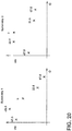
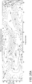
- FIG. 26A shows an example of an efficiency map in the frequency/phase domain where the system is mostly symmetrical and most of the resonances are around 0° (first symmetry plane) and 180° (second symmetry plane). Such resonances would not need to be rotated. In this example, the highest efficiency (coupling) is obtained using the nominal axis (first: 0°, second 180°).
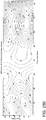
- FIG. 26B shows an example of an efficiency map in the frequency/phase domain where the system is asymmetrical and most of the resonances are not around either 0° (first symmetry plane) or 180° (second symmetry plane). Such resonances may be subject to rotation. In this example, the highest efficiency (coupling) is obtained applying specific rotations to each pole. If the nominal axis (first: 0°, second 180°) were used, a lower efficiency would be obtained.
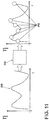
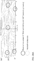
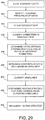
- the controller 14 determines paths defining stirring routes between poles of different symmetries in step 458. It then determines midpoints in the paths with a maximum unbalance between reflected powers of the plurality of respective high power amplifiers in step 460.
- the controller 14 classifies the unbalance in terms of power steered to a left side of the food load with respect to power steered to a right side of the food load in step 462. It then synthesizes a heating strategy for zone cooking using the classified unbalance in step 464.
- the controller 14 implements the heating strategy in step 466 by causing the plurality of high power amplifiers and RF feeds to introduce electromagnetic radiation at specific frequencies and phases into the cavity, wherein the specific frequencies and phases are selected in accordance with the heating strategy.
- step 502 substep (1), the controller 14 first excites the cavity with a plurality of pre-selected frequencies to identify unrotated resonant modes and then identifies a set of excitations for each unrotated resonant mode to be analyzed by acting on a plurality of phase-shifts and keeping the frequency locked for that resonant mode. Specifically, for each unrotated resonant mode, the controller 14 generates a set of excitations with the same frequency (of the nominal mode) and a combination of phase-shifts.
- the set of phases might be defined a-priori, statically defined on run-time, or even be adaptive according to different parameters.
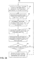
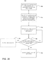
- the controller 14 monitors the coefficient of variation of efficiency (step 746), and if the coefficient of variation of efficiency is greater than or equal to the threshold for a predetermined period of time (step 748), it is determined that the liquid is in the strong boiling state, and in response, the controller 14 adjusts a power level of amplifiers 18A-D (e.g., changing a duty cycle, input power, etc.) (step 750). Otherwise, the controller 14 determines that the liquid is in a weak boiling state and continues to monitor the coefficient of variation of efficiency (step 746) until the condition specified at step 748 is satisfied.
- a power level of amplifiers 18A-D e.g., changing a duty cycle, input power, etc.
- the controller 14 monitors the coefficient of variation of efficiency (step 766), and if the coefficient of variation of efficiency fits to the mask for a predetermined period of time (step 768), the controller 14 determines that the liquid is in the strong boiling state, and in response, adjusts a power level of amplifiers 18A-D (step 770). Otherwise, the controller 14 determines that the liquid is the weak boiling state and continues to monitor the coefficient of variation of efficiency (step 746) until the condition specified at step 768 is satisfied. With respect to step 770, the adjustment may include maintaining the power level, increasing the power level, decreasing the power level, or stopping the heating of the liquid altogether.
- the controller 14 may output a notification to the user interface 28 or a mobile device such as a smartphone (step 772).
- a user may provide input to the controller 14 (via the user interface 28 or the mobile device) accepting the adjustments made at step 770 or otherwise making other adjustments, if desired.
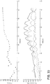
- sample data is shown for the coefficient of variation (metric output) of efficiency for a liquid heated in the cooking cavity 20 over a period of time.
- the liquid may correspond to a sauce, for example.
- the liquid may be part of a mixed load, that is, a food load having both liquid and solid constituents.
- method 860 begins with the controller 14 measuring the coefficient of variation of efficiency (step 862).
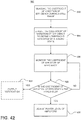
- the controller 14 monitors the coefficient of variation of efficiency (step 864), and if the coefficient of variation of efficiency falls below the threshold defined in step 844 of method 840 (step 866) for a predetermined period of time, the controller 14 adjusts (e.g., decreases) the power level and may also assign a time limit in which to end the popping process (step 868). Alternatively, the controller 14 may stop the popping process immediately.
- the controller 14 continues to monitor the coefficient of variation of efficiency (step 864) until the condition specified at step 866 is satisfied.
- the controller 14 may output a notification to the user interface 28 or a mobile device such as a smartphone (step 870).
- a user may provide input to the controller 14 (via the user interface 28 or the mobile device) accepting the adjustments described at step 868 or otherwise making other adjustments to the power level and/or time limit, if desired.
- the system 10 is operable to quantify the amount of variation in the system 10 due to changes in the food load (e.g. temperature rise due to dielectric heating). In this way, the system can detect various changes in the food load for one or more automatic cooking functions.
- changes in the food load e.g. temperature rise due to dielectric heating
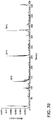
- the controller may select a pre-stored map of efficiency showing resonance modes corresponding to a completely cooked food load of the type of the identified food load, identify Q-factors of the resonance modes in the pre-stored map, and compare the maps of efficiency stored during the cooking process to the pre-stored map to determine when the at least one Q-factor changes to a Q-factor that is identified from the pre-stored map, which is indicative of completion of cooking.
- doneness or a cooking level may correspond to a temperature that may indicate a completion of heating a food load to a desired level in the cooking cavity 20. Accordingly, in various embodiments, the controller 14 may determine a cooking temperature or level of preparation or doneness independent of an elapsed cooking time and independent of a starting temperature of the food load.
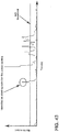
- the controller 14 may identity an increase in the rate of change of the Q-factor exceeding a predetermined threshold for the potato. Accordingly, the controller 14 may consistently identify the fourth change 932 in the potato and automatically stop or adjust the cooking cycle in response to the detection of the fourth change 942.
- the fourth change 942 may correspond to a starch gelatinization of the potato starch. Accordingly, in response to identifying the fourth change 942, the controller 14 may identify starch gelatinization of the potato starch and adjust or stop a cooking cycle.
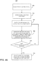
- the controller 14 may monitor the Q-factor to identify a change in the Q-factor exceeding a predetermined change threshold in step 960.
- the predetermined change threshold may correspond to a predetermined rate of change, predetermined direction (increase or decrease) of a rate of change, and/or a predetermined change or sequence of changes in reference to a current direction, trend, or rate of change of the Q-factor. Some examples of detections of rates and directions (increases or decreases) in rates of change are discussed in reference to FIGS. 47 , 48 , and 49 . If the change in the Q-factor does not exceed the predetermined threshold, the method 950 may return to step 958.
- controller 14 all or portions of the methods may be performed by RF control 32 or any other controller, microprocessor, microcontroller, logic circuit, or programmed gate array, either separately or in combination.
Landscapes
- Physics & Mathematics (AREA)
- Electromagnetism (AREA)
- Engineering & Computer Science (AREA)
- Power Engineering (AREA)
- Control Of High-Frequency Heating Circuits (AREA)
- Constitution Of High-Frequency Heating (AREA)
Claims (15)
- Verfahren, um eine Heizverteilung einer elektromagnetischen Kochvorrichtung (10) zu steuern, umfassend:Abtasten eines Resonanzhohlraums (20, 222) der Kochvorrichtung (10), in der eine Lebensmittelladung platziert wurde, mit einer Vielzahl von HF-Einspeisungen (26A-26D, 226A, 226B), die mit einer Vielzahl von jeweiligen Hochleistungsverstärkern (18A-18D) gekoppelt sind;Identifizieren einer Vielzahl von Resonanzfrequenzen und entsprechenden Phasen der HF-Einspeisungen (26A-26D, 226A, 226B) auf Basis der Abtastung;Erstellen und Speichern einer Resonanzkarte im Frequenzphasenbereich;Klassifizieren von Symmetrien in der Resonanzkarte;Bestimmen von Pfaden, die Rührwege zwischen Polen unterschiedlicher Symmetrien definieren;Bestimmen von Mittelpunkten in den Pfaden mit einem maximalen Ungleichgewicht zwischen reflektierten Leistungen der Vielzahl von jeweiligen Hochleistungsverstärkern (18A-18D);Klassifizieren des Ungleichgewichts im Hinblick auf Leistung, die zu einer ersten Seite der Lebensmittelladung gelenkt wird, im Verhältnis zu Leistung, die zu einer zweiten Seite der Lebensmittelladung gelenkt wird;Entwickeln einer Heizstrategie für Zonenkochen unter Verwendung des klassifizierten Ungleichgewichts; undImplementieren der Heizstrategie, indem die Vielzahl von Hochleistungsverstärkern (18A-18D) und HF-Einspeisungen (26A-26D, 226A, 226B) dazu gebracht werden, elektromagnetische Strahlung mit bestimmten Frequenzen und Phasen in den Hohlraum (20, 222) einzuleiten, wobei die bestimmten Frequenzen und Phasen in Übereinstimmung mit der Heizstrategie ausgewählt werden.
- Verfahren nach Anspruch 1, wobei Informationen, die zum Klassifizieren des Ungleichgewichts verwendet werden, in einer Nachschlagetabelle (LUT) vorgespeichert und unter Verwendung von mindestens einem abgerufen werden können aus: einem Rezept; einem computergestützten elektromagnetischen Motor; und einer IR-Sensorprüfung von mindestens einem von zwei asymmetrischen Pfaden.
- Verfahren nach einem der Ansprüche 1-2, wobei die in den Hohlraum (20, 222) eingeleitete elektromagnetische Strahlung gemäß den Rührwegen schrittweise verändert wird.
- Verfahren nach Anspruch 3, wobei die schrittweise Änderung der elektromagnetischen Strahlung eine fließende Änderung der Vielzahl von HF-Einspeisungen (26A-26D, 226A, 226B) erzielt, wodurch ein Heizmuster der Resonanzkammer über die Zeit hinweg fließend verändert wird.
- Verfahren nach einem der Ansprüche 1-4, wobei eine Änderungsrate der elektromagnetischen Strahlung, die entlang der Rührwege in den Hohlraum (20, 222) eingeleitet wird, gesteuert wird.
- Verfahren nach einem der Ansprüche 1-5, wobei es sich bei der ersten Seite der Lebensmittelladung um die rechte Seite handelt, und bei der zweiten Seite der Lebensmittelladung um die linke Seite handelt.
- Verfahren nach einem der Ansprüche 1-6, weiter das Bereitstellen eines Messsystems (150) in umfassend, das dazu konfiguriert ist, eine Vielzahl von reflektierten Signalen von den HF-Einspeisungen (26A-26D, 226A, 226B) zu messen.
- Verfahren nach Anspruch 7, weiter umfassend:
Messen einer Effizienz der Vielzahl von reflektierten Signalen mit dem Messsystem (150). - Verfahren nach einem der Ansprüche 1-8, wobei die Resonanzmoden die Frequenz und Phase von Koordinaten von Endpunkten identifizieren, wobei der Rührweg Koordinatenpunkte zwischen den Endpunkten einschließt.
- Verfahren nach Anspruch 9, wobei die Koordinaten Punkten der Resonanzmoden im Frequenz- und Phasenbereich entsprechen.
- Elektromagnetische Kochvorrichtung (10), umfassend:einen umschlossenen Hohlraum (20, 222), der dazu konfiguriert ist, eine Lebensmittelladung aufzunehmen;eine Vielzahl von Hochleistungsverstärkern (18A-18D), die dazu konfiguriert sind, ein erstes HF-Signal und ein zweites HF-Signal zu verstärken, wodurch die HF-Signale dem umschlossenen Hohlraum (20) zugeführt werden;eine Vielzahl von HF-Einspeisungen (26A-26D, 226A, 226B) zum Empfangen der HF-Signale von der Vielzahl von Hochleistungsverstärkern (18A-18D), um elektromagnetische Strahlung entsprechend den HF-Signalen in den umschlossenen Hohlraum (20) einzuleiten; undeine Steuerung (14), die mit der Vielzahl von Verstärkern (18A-18D) in Kommunikation steht, wobei die Steuerung (14) dazu konfiguriert ist:den umschlossenen Hohlraum unter Verwendung der Vielzahl von HF-Einspeisungen (26A-26D, 226A, 226B) abzutasten;auf Basis der Abtastung eine Vielzahl von Resonanzfrequenzen und entsprechenden Phasen der HF-Einspeisungen (26A-26D, 226A, 226B) zu identifizieren;eine Resonanzkarte im Frequenzphasenbereich zu erstellen und zu speichern;Symmetrien in der Resonanzkarte zu klassifizieren;Pfade zu bestimmen, die Rührwege zwischen Polen unterschiedlicher Symmetrien definieren;Mittelpunkte in den Pfaden mit einem maximalen Ungleichgewicht zwischen reflektierten Leistungen der Vielzahl von jeweiligen Hochleistungsverstärkern (18A-18D) zu bestimmen;das Ungleichgewicht im Hinblick auf Leistung, die zu einer ersten Seite der Lebensmittelladung gelenkt wird, im Verhältnis zu Leistung, die zu einer zweiten Seite der Lebensmittelladung gelenkt wird, zu klassifizieren;unter Verwendung des klassifizierten Ungleichgewichts einer Heizstrategie für Zonenkochen zu entwickeln; unddie Heizstrategie zu implementieren, indem die Vielzahl von Hochleistungsverstärkern (18A-18D) und HF-Einspeisungen (26A-26D, 226A, 226B) dazu gebracht werden, die elektromagnetische Strahlung mit bestimmten Frequenzen und Phasen in den Hohlraum (20, 222) einzuleiten, wobei die bestimmten Frequenzen und Phasen in Übereinstimmung mit der Heizstrategie ausgewählt werden.
- Kochvorrichtung nach Anspruch 11, wobei Informationen, die von der Steuerung (14) zum Klassifizieren des Ungleichgewichts verwendet werden, in einer Nachschlagetabelle (LUT) vorgespeichert und unter Verwendung von mindestens einem abgerufen werden können aus: einem Rezept; einem computergestützten elektromagnetischen Motor; und einer IR-Sensorprüfung von mindestens einem von zwei asymmetrischen Pfaden.
- Kochvorrichtung nach einem der Ansprüche 11-12, weiter umfassend:
ein Messsystem (150), das mit der Steuerung (14) in Kommunikation steht, wobei das Messsystem (150) dazu konfiguriert ist, eine Vielzahl von reflektierten Signalen von den HF-Einspeisungen (26A-26D, 226A, 226B) zu messen. - Kochvorrichtung nach Anspruch 13, wobei die Steuerung weiter dazu konfiguriert ist:
mit dem Messsystem (150) eine Effizienz der Vielzahl von reflektierten Signalen zu messen. - Kochvorrichtung nach Anspruch 14, wobei die Steuerung weiter dazu konfiguriert ist, auf Basis der Effizienz eine Vielzahl von Resonanzfrequenzen zu identifizieren.
Applications Claiming Priority (1)
| Application Number | Priority Date | Filing Date | Title |
|---|---|---|---|
| US15/910,340 US10772165B2 (en) | 2018-03-02 | 2018-03-02 | System and method for zone cooking according to spectromodal theory in an electromagnetic cooking device |
Publications (2)
| Publication Number | Publication Date |
|---|---|
| EP3534675A1 EP3534675A1 (de) | 2019-09-04 |
| EP3534675B1 true EP3534675B1 (de) | 2020-08-05 |
Family
ID=65598549
Family Applications (1)
| Application Number | Title | Priority Date | Filing Date |
|---|---|---|---|
| EP19159444.9A Not-in-force EP3534675B1 (de) | 2018-03-02 | 2019-02-26 | System und verfahren zum zonenkochen nach spektrometrischer theorie in einer elektromagnetischen kochvorrichtung |
Country Status (2)
| Country | Link |
|---|---|
| US (1) | US10772165B2 (de) |
| EP (1) | EP3534675B1 (de) |
Families Citing this family (9)
| Publication number | Priority date | Publication date | Assignee | Title |
|---|---|---|---|---|
| EP3563638B1 (de) * | 2016-12-29 | 2021-09-01 | Whirlpool Corporation | Elektromagnetische kochvorrichtung mit automatischem schmelzbetrieb und verfahren zur kochsteuerung bei der elektromagnetischen kochvorrichtung |
| JP6830151B2 (ja) * | 2016-12-29 | 2021-02-17 | パナソニック株式会社 | 自動沸騰検出を備えた電磁調理装置および電磁調理装置の調理を制御する方法 |
| EP3849278B1 (de) * | 2018-09-07 | 2025-08-27 | Panasonic Intellectual Property Management Co., Ltd. | Hf-energiestrahlvorrichtung |
| US11289946B2 (en) * | 2019-04-08 | 2022-03-29 | Purdue Research Foundation | Method and system of uniform wireless power distribution within a chamber |
| US11576408B2 (en) * | 2019-04-15 | 2023-02-14 | Bsh Home Appliances Corporation | Ice processing system |
| WO2021020373A1 (ja) * | 2019-07-31 | 2021-02-04 | パナソニックIpマネジメント株式会社 | マイクロ波処理装置 |
| EP3793327B1 (de) * | 2019-09-10 | 2022-11-30 | Electrolux Appliances Aktiebolag | Verfahren zum betreiben einer mikrowellenvorrichtung |
| CN116830802A (zh) * | 2021-02-19 | 2023-09-29 | 松下知识产权经营株式会社 | Rf能量辐射装置 |
| CN113459508B (zh) * | 2021-07-08 | 2023-03-10 | 杭州电子科技大学 | 一种多通道的汇流式生物打印喷头 |
Family Cites Families (246)
| Publication number | Priority date | Publication date | Assignee | Title |
|---|---|---|---|---|
| GB639470A (en) | 1946-08-27 | 1950-06-28 | Jiri Stivin | A device for repeated starting and stopping of an oscillation generator |
| US2742612A (en) | 1950-10-24 | 1956-04-17 | Sperry Rand Corp | Mode transformer |
| US2956143A (en) | 1958-06-05 | 1960-10-11 | Raytheon Co | Microwave ovens |
| US2958754A (en) | 1958-12-15 | 1960-11-01 | Gen Electric | Electronic ovens |
| US2981904A (en) | 1959-01-06 | 1961-04-25 | Hughes Aircraft Co | Microwave transition device |
| US3260832A (en) | 1963-10-28 | 1966-07-12 | Westinghouse Electric Corp | Oven |
| US3265995A (en) | 1964-03-18 | 1966-08-09 | Bell Telephone Labor Inc | Transmission line to waveguide junction |
| US3440385A (en) | 1965-10-13 | 1969-04-22 | Microtherm Ltd | Electronic ovens |
| US3430023A (en) | 1967-09-11 | 1969-02-25 | Roper Corp Geo D | Door construction and ventilating system for microwave oven |
| US3489135A (en) | 1968-06-21 | 1970-01-13 | Indian Head Inc | Oven door construction |
| US3536129A (en) | 1968-11-19 | 1970-10-27 | Varian Associates | Method for thawing frozen water-bearing substances utilizing microwave energy |
| US3639717A (en) | 1970-09-08 | 1972-02-01 | Mitsubishi Electric Corp | Switch actuator for an electronic cooking device |
| US3731035A (en) | 1971-11-15 | 1973-05-01 | Litton Systems Inc | Microwave oven door |
| DE2320438A1 (de) | 1972-06-26 | 1974-01-10 | Litton Industries Inc | Mikrowellenherd |
| US3737812A (en) | 1972-09-08 | 1973-06-05 | Us Navy | Broadband waveguide to coaxial line transition |
| US3812316A (en) | 1973-03-28 | 1974-05-21 | Gen Electric | Door seal gasket for combined microwave and self-cleaning oven |
| US4000390A (en) | 1975-02-14 | 1976-12-28 | Hobart Corporation | Microwave oven door |
| US4136271A (en) | 1976-02-03 | 1979-01-23 | Matsushita Electric Industrial Co., Ltd. | Microwave oven |
| US4088861A (en) | 1976-03-18 | 1978-05-09 | Mcgraw-Edison Company | Microwave oven with torsion bar hinge |
| JPS52121838A (en) | 1976-04-06 | 1977-10-13 | Matsushita Electric Ind Co Ltd | High frequency heating device |
| FR2359522A1 (fr) | 1976-07-20 | 1978-02-17 | Thomson Csf | Transition entre une ligne coaxiale et un guide d'ondes, et circuits hyperfrequences comportant une telle transition |
| USD248607S (en) | 1976-11-19 | 1978-07-25 | Matsushita Electric Industrial Co., Ltd. | Microwave oven |
| US4166207A (en) | 1977-05-31 | 1979-08-28 | Whirlpool Corporation | Microwave generating device--door seal |
| US4101750A (en) | 1977-05-31 | 1978-07-18 | Whirlpool Corporation | Door interlock system for microwave oven |
| US4143646A (en) | 1977-10-27 | 1979-03-13 | Home Metal Products Company A Division Of Mobex Corporation | Cooking apparatus and exhaust system |
| CA1081796A (en) | 1978-02-09 | 1980-07-15 | Canadian Patents And Development Limited | Controlled heating microwave ovens using different operating frequencies |
| US4283614A (en) | 1978-02-20 | 1981-08-11 | Matsushita Electric Industrial Co., Ltd. | Cooking device with high-frequency heating means and resistance heating means |
| JPS55155120A (en) | 1979-05-18 | 1980-12-03 | Sanyo Electric Co Ltd | Electronic control type cooker |
| US4264800A (en) | 1979-06-08 | 1981-04-28 | Minnesota Mining And Manufacturing Company | Microwave oven window |
| US4374319A (en) | 1979-11-27 | 1983-02-15 | Sunset Ltd. | Counter-top oven |
| US4321445A (en) | 1980-01-28 | 1982-03-23 | Whirlpool Corporation | Door latch interlock system for microwave oven |
| USD268079S (en) | 1980-02-04 | 1983-03-01 | Sharp Corporation | Microwave oven |
| US4354562A (en) | 1980-12-03 | 1982-10-19 | Newman Martin H | Electronic weighing device |
| JPS57194296U (de) | 1981-06-04 | 1982-12-09 | ||
| US4463324A (en) | 1982-06-03 | 1984-07-31 | Sperry Corporation | Miniature coaxial line to waveguide transition |
| USD276122S (en) | 1982-07-08 | 1984-10-30 | Matsushita Electric Industrial Co., Ltd. | Microwave oven |
| USD275546S (en) | 1982-07-08 | 1984-09-18 | Matsushita Electric Industrial Co., Ltd. | Microwave oven |
| DE3238441A1 (de) | 1982-10-16 | 1984-04-19 | Licentia Patent-Verwaltungs-Gmbh, 6000 Frankfurt | Back- und bratofen |
| USD285893S (en) | 1982-12-28 | 1986-09-30 | Matsushita Electric Industrial Co. | Front panel for a microwave oven |
| USD277355S (en) | 1982-12-30 | 1985-01-29 | Sharp Kabushiki Kaisha | Microwave oven |
| JPS59226497A (ja) | 1983-06-06 | 1984-12-19 | 松下電器産業株式会社 | 高周波加熱装置 |
| USD297800S (en) | 1983-10-31 | 1988-09-27 | Bosch-Siemens Hausgerate Gmbh | Compact oven |
| US4703151A (en) | 1984-01-05 | 1987-10-27 | Matsushita Electric Industrial Co., Ltd. | Heating cooking appliance having weight detecting function |
| US4628351A (en) | 1984-04-23 | 1986-12-09 | Samsung Electronics Co., Ltd. | Cooking apparatus with a video display |
| US4786774A (en) | 1984-04-27 | 1988-11-22 | Sharp Kabushiki Kaisha | Combination compact microwave oven and ventilator system |
| DE8413224U1 (de) | 1984-04-30 | 1984-08-16 | Licentia Patent-Verwaltungs-Gmbh, 6000 Frankfurt | Tuer fuer den back- und bratraum eines bratofens |
| US4595827A (en) | 1984-05-02 | 1986-06-17 | Matsushita Electric Industrial Co., Ltd. | Cooking apparatus with weighing device |
| USD297698S (en) | 1984-12-26 | 1988-09-20 | Imanishi Kinzoku Kogyo Kabushiki Kaisha | Microwave oven |
| CA1253923A (en) | 1985-04-15 | 1989-05-09 | Ichiroh Hori | High frequency heating apparatus with electric heating device |
| AU97420S (en) | 1986-04-22 | 1987-08-13 | Sharp Kk | Microwave oven |
| US4743728A (en) | 1986-05-31 | 1988-05-10 | Kabushiki Kaisha Toshiba | Dual path air circulation system for microwave ovens |
| GB8618218D0 (en) | 1986-07-25 | 1986-09-03 | Magnetronics Ltd | Edible product manufacture |
| DE3710796A1 (de) | 1987-03-31 | 1988-10-13 | Miele & Cie | Mikrowellenherd mit einem drehteller |
| US4870238A (en) | 1987-10-26 | 1989-09-26 | Hodgetts Michael J | Microwave oven popcorn control |
| US4886046A (en) | 1987-10-26 | 1989-12-12 | Whirlpool Corporation | Motor control circuit for an eye level range |
| US4937413A (en) | 1987-10-26 | 1990-06-26 | Microwave Products Of America, Inc. | Acoustic sensor assembly for a microwave oven |
| CA1318014C (en) | 1989-07-06 | 1993-05-18 | Kevin Smith | Sealing enclosures against electromagnetic interference |
| US5075525A (en) | 1990-06-25 | 1991-12-24 | Goldstar Co., Ltd. | Wave shielding device for microwave oven |
| US6097019A (en) | 1990-07-11 | 2000-08-01 | International Business Machines Corporation | Radiation control system |
| US6054696A (en) | 1997-01-06 | 2000-04-25 | International Business Machines Corporation | Feedback system to automatically couple microwave energy into an applicator |
| CA2066725C (en) | 1990-07-25 | 1996-06-04 | Yuji Nakabayashi | High-frequency heating apparatus |
| USD330144S (en) | 1990-07-31 | 1992-10-13 | Matsushita Electric Industrial Co., Ltd. | Microwave oven |
| JP2987470B2 (ja) | 1991-07-05 | 1999-12-06 | 株式会社日立ホームテック | 加熱調理装置 |
| AU118758S (en) | 1992-07-21 | 1993-11-11 | Sharp Kk | Microwave oven |
| JPH06147492A (ja) | 1992-11-17 | 1994-05-27 | Matsushita Electric Ind Co Ltd | 高周波加熱装置 |
| KR950002891Y1 (ko) | 1993-01-12 | 1995-04-17 | 주식회사 금성사 | 전자레인지의 중량 검출장치 |
| FR2705765B1 (fr) | 1993-04-29 | 1995-08-18 | Eurofours Sa | Porte de four. |
| US5483045A (en) | 1994-06-09 | 1996-01-09 | Electric Power Research Institute | Microwave power system and method with exposure protection |
| DE4431619A1 (de) | 1994-09-05 | 1996-03-07 | Bosch Siemens Hausgeraete | Herdtür eines Kochherdes |
| JPH08171986A (ja) | 1994-12-19 | 1996-07-02 | Hitachi Ltd | マイクロ波加熱装置 |
| FR2732097B1 (fr) | 1995-03-24 | 1997-05-23 | Seb Sa | Porte de four simplifiee avec module amovible |
| US5619983A (en) | 1995-05-05 | 1997-04-15 | Middleby Marshall, Inc. | Combination convection steamer oven |
| US5558800A (en) | 1995-06-19 | 1996-09-24 | Northrop Grumman | Microwave power radiator for microwave heating applications |
| ES2110904B1 (es) | 1995-07-17 | 1998-10-01 | Montserrat Gibernau Antonio | Maquina expendedora de productos alimenticios envasados. |
| KR0171337B1 (ko) | 1995-09-18 | 1999-05-01 | 배순훈 | 전자렌지 도어의 전파 차폐구조 |
| US5696678A (en) | 1995-12-19 | 1997-12-09 | Ford Global Technologies, Inc. | Method for preventing undesirable lowering of an air suspension system |
| KR100218958B1 (ko) | 1996-02-23 | 1999-09-01 | 윤종용 | 전자렌지의 트레이 구동 제어방법 |
| USD385155S (en) | 1996-05-23 | 1997-10-21 | White Consolidated Industries, Inc. | Microwave oven front panel |
| FR2751055B1 (fr) | 1996-07-15 | 1998-09-25 | Moulinex Sa | Four electrique de cuisson |
| USD378723S (en) | 1996-11-06 | 1997-04-08 | White Consolidated Industries, Inc. | Microwave oven |
| US5981929A (en) | 1996-12-20 | 1999-11-09 | Matsushita Electric Industrial Co., Ltd. | Heating cooker with a space-efficient ventilating arrangement |
| CA2229951C (en) | 1997-03-18 | 2002-05-07 | Sanyo Electric Co., Ltd. | Cooking apparatus including infrared ray sensor |
| RU2122338C1 (ru) | 1997-04-08 | 1998-11-27 | Георгий Галиуллович Валеев | Устройство для приготовления пищи |
| FR2766272B1 (fr) | 1997-07-15 | 1999-10-15 | Moulinex Sa | Dispositif et procede de reflectometrie hyperfrequences, et four a micro-ondes ainsi equipe |
| AU136256S (en) | 1997-12-22 | 1999-01-19 | Sharp Kk | Microwave oven |
| US6097018A (en) | 1998-04-06 | 2000-08-01 | Lg Electronics Inc. | Circular polarization generating system for microwave oven |
| KR100284548B1 (ko) | 1998-06-16 | 2001-05-02 | 윤종용 | 전자렌지용 후드팬의 설치구조 |
| US6557756B1 (en) | 1998-09-04 | 2003-05-06 | Ncr Corporation | Communications, particularly in the domestic environment |
| KR100341288B1 (ko) | 1998-11-11 | 2002-10-25 | 삼성전자 주식회사 | 직류전원을단속하는마이크로스위치의과전류를방지할수있는전자렌지 |
| WO2000036880A2 (en) | 1998-12-17 | 2000-06-22 | Personal Chemistry I Uppsala Ab | Microwave apparatus and methods for performing chemical reactions |
| US6559882B1 (en) | 1999-09-02 | 2003-05-06 | Ncr Corporation | Domestic appliance |
| JP3620818B2 (ja) | 1999-04-16 | 2005-02-16 | 株式会社三協精機製作所 | 重量検出装置および電子レンジ |
| JP3485846B2 (ja) | 1999-10-29 | 2004-01-13 | 三洋電機株式会社 | 加熱調理装置 |
| EE200200495A (et) | 2000-02-25 | 2004-02-16 | Personal Chemistry I Uppsala Ab | Mikrolainekuumutusseade |
| US6853399B1 (en) | 2000-05-26 | 2005-02-08 | Robert A. Gilman | Kitchen appliance with video display |
| GB2367196B (en) | 2000-07-27 | 2002-09-25 | Samsung Electronics Co Ltd | Microwave oven having a switching power supply |
| US6429370B1 (en) | 2000-08-31 | 2002-08-06 | Avaya Technology Corp. | Self-adhering electromagnetic interference door seal |
| DE60016412T2 (de) | 2000-09-29 | 2006-03-02 | Whirlpool Corp., Benton Harbor | Kochsystem und Anwendung in einem Ofen |
| ATE339662T1 (de) | 2001-02-13 | 2006-10-15 | Arcelik As | Haushaltsgerät |
| US7111247B2 (en) | 2001-07-02 | 2006-09-19 | Lg Electronics Inc. | Device and method for controlling menu display of microwave oven |
| US20050162335A1 (en) | 2002-03-08 | 2005-07-28 | Tokyo Electron Limited | Plasma device |
| US6984811B2 (en) | 2002-03-11 | 2006-01-10 | Lg Electronics, Inc. | Door for microwave oven having integrally formed control unit |
| EP2405711B1 (de) | 2002-06-26 | 2015-05-06 | Mitsui Engineering and Shipbuilding Co, Ltd. | Induktionsheizverfahren und -einheit |
| RU2003111214A (ru) | 2002-07-02 | 2004-11-20 | Эл Джи Электроникс Инк. | Устройство, содержащее печь и радиоприемник, способ прекращения работы радиоприемника, когда включают печь, устройство радиоприемник - микроволновая печь (варианты) и способ прослушивания радиоприемника |
| US7105787B2 (en) | 2002-10-29 | 2006-09-12 | Fiore Industries, Inc. | Reverberating adaptive microwave-stirred exposure system |
| KR20040047083A (ko) | 2002-11-29 | 2004-06-05 | 삼성전자주식회사 | 전자레인지 및 그 제어방법 |
| DE10256624B4 (de) | 2002-12-03 | 2005-12-08 | Miele & Cie. Kg | Mikrowellenherd |
| USD495556S1 (en) | 2002-12-09 | 2004-09-07 | Bsh Home Appliances Corporation | Range |
| DE10307217B4 (de) | 2003-02-20 | 2006-04-13 | Schott Ag | Tür mit Sichtfenster für Mikrowellengeräte |
| USD481582S1 (en) | 2003-03-25 | 2003-11-04 | Whirlpool Corporation | Countertop oven |
| US20040206755A1 (en) | 2003-04-18 | 2004-10-21 | Hadinger Peter James | Microwave heating using distributed semiconductor sources |
| EP1619933A1 (de) | 2003-04-25 | 2006-01-25 | Matsushita Electric Industrial Co., Ltd. | Hochfrequenzerwärmungseinrichtung und verfahren zu ihrer steuerung |
| JP4372099B2 (ja) | 2003-05-15 | 2009-11-25 | オムロン株式会社 | 高周波加熱装置 |
| KR20050002121A (ko) | 2003-06-30 | 2005-01-07 | 주식회사 대우일렉트로닉스 | 팝콘 자동 조리 기능을 갖는 전자렌지 및 그 방법 |
| WO2005008137A1 (en) | 2003-07-16 | 2005-01-27 | Lg Electronics,Inc. | Door opening and closing system in electric oven |
| RU2253193C2 (ru) | 2003-07-21 | 2005-05-27 | Санкт-Петербургский государственный университет | Микроволновая печь и способ оптимизации ее конструктивных параметров |
| KR100577196B1 (ko) | 2003-12-02 | 2006-05-10 | 엘지전자 주식회사 | 커피 메이커 겸용 전자레인지 및 그 제어방법 |
| DE102004002466A1 (de) | 2004-01-16 | 2005-08-11 | BSH Bosch und Siemens Hausgeräte GmbH | Haushaltsgerätetür mit einer Vorrichtung mit einer Scharniereinheit |
| JP2006010122A (ja) | 2004-06-23 | 2006-01-12 | Matsushita Electric Ind Co Ltd | レンジフード付き高周波加熱装置 |
| US7193195B2 (en) | 2004-07-01 | 2007-03-20 | Whirlpool Corporation | Wall mounted microwave oven having a top vent with filter system |
| AU305036S (en) | 2004-10-04 | 2006-01-18 | Lg Electronics Inc | Microwave oven |
| USD531447S1 (en) | 2004-10-29 | 2006-11-07 | Lg Electronics Inc. | Microwave oven |
| USD530973S1 (en) | 2004-10-29 | 2006-10-31 | Lg Electronics Inc. | Microwave oven |
| USD527572S1 (en) | 2005-03-11 | 2006-09-05 | Lg Electronics Inc. | Oven |
| USD521799S1 (en) | 2005-03-18 | 2006-05-30 | Whirlpool Corporation | Countertop oven |
| USD540105S1 (en) | 2005-03-24 | 2007-04-10 | Lg Electronics Inc. | Microwave oven |
| USD532645S1 (en) | 2005-03-24 | 2006-11-28 | Lg Electronics Inc. | Microwave oven |
| US7476828B2 (en) | 2005-06-10 | 2009-01-13 | Marc Genua | Media microwave oven |
| KR20060128372A (ko) | 2005-06-10 | 2006-12-14 | 삼성전자주식회사 | 오븐 |
| DE102005028253B3 (de) | 2005-06-17 | 2006-11-02 | Emz-Hanauer Gmbh & Co. Kgaa | Vorrichtung und Verfahren zur Erfassung der Unwucht einer drehbaren Komponente eines Haushaltsgeräts und Haushaltsgerät damit |
| EP1795814A3 (de) | 2005-12-06 | 2011-01-26 | LG Electronics Inc. | Elektrischer Ofen |
| US7770985B2 (en) | 2006-02-15 | 2010-08-10 | Maytag Corporation | Kitchen appliance having floating glass panel |
| WO2008102360A2 (en) | 2007-02-21 | 2008-08-28 | Bora Appliances Limited | Drying apparatus and methods and accessories for use therewith |
| US10674570B2 (en) | 2006-02-21 | 2020-06-02 | Goji Limited | System and method for applying electromagnetic energy |
| US8653482B2 (en) | 2006-02-21 | 2014-02-18 | Goji Limited | RF controlled freezing |
| CA117670S (en) | 2006-06-29 | 2007-10-24 | Sharp Kk | Oven |
| CN101118425A (zh) | 2006-08-01 | 2008-02-06 | 上海中策工贸有限公司 | 营养加工系统 |
| JP5064924B2 (ja) | 2006-08-08 | 2012-10-31 | パナソニック株式会社 | マイクロ波処理装置 |
| USD540613S1 (en) | 2006-09-15 | 2007-04-17 | Samsung Electronics Co., Ltd. | Electronic oven |
| USD550024S1 (en) | 2006-09-15 | 2007-09-04 | Samsung Electronics Co., Ltd. | Electronic oven |
| JP4967600B2 (ja) | 2006-10-24 | 2012-07-04 | パナソニック株式会社 | マイクロ波処理装置 |
| KR101291426B1 (ko) | 2007-01-02 | 2013-07-30 | 엘지전자 주식회사 | 후드 겸용 전자 레인지 |
| EP2127481A1 (de) | 2007-02-21 | 2009-12-02 | RF Dynamics Ltd. | Hf-gesteuertes einfrieren |
| DE102007012378A1 (de) | 2007-03-14 | 2008-09-18 | BSH Bosch und Siemens Hausgeräte GmbH | Hausgerät, insbesondere Backofen |
| US9131543B2 (en) | 2007-08-30 | 2015-09-08 | Goji Limited | Dynamic impedance matching in RF resonator cavity |
| EP2031938B1 (de) | 2007-09-03 | 2013-02-27 | Electrolux Home Products Corporation N.V. | Drosselspulensystem für eine Mikrowellenherdtür |
| EP2031937B1 (de) | 2007-09-03 | 2010-01-27 | Electrolux Home Products Corporation N.V. | Tür mit Drosselspulensystem für einen Mikrowellenherd |
| EP2031939B1 (de) | 2007-09-03 | 2013-02-27 | Electrolux Home Products Corporation N.V. | Drosselspulenvorrichtung für eine Mikrowellenherdtür |
| CN201081287Y (zh) | 2007-09-12 | 2008-07-02 | 广东格兰仕集团有限公司 | 带蒸汽功能的热风对流微波炉 |
| US8236144B2 (en) | 2007-09-21 | 2012-08-07 | Rf Thummim Technologies, Inc. | Method and apparatus for multiple resonant structure process and reaction chamber |
| EP2205043B1 (de) | 2007-10-18 | 2017-01-25 | Panasonic Corporation | Mikrowellenheizvorrichtung |
| KR101450879B1 (ko) | 2007-11-28 | 2014-10-14 | 엘지전자 주식회사 | 밴트그릴 |
| JP2009156546A (ja) | 2007-12-27 | 2009-07-16 | Panasonic Corp | 加熱調理器 |
| AU320419S (en) | 2008-03-28 | 2008-07-29 | Breville R & D Pty Ltd | Toaster oven |
| KR101004863B1 (ko) | 2008-04-01 | 2010-12-28 | 엘지전자 주식회사 | 전자레인지 |
| RU2390096C2 (ru) | 2008-04-21 | 2010-05-20 | Государственное образовательное учреждение высшего профессионального образования Академия Федеральной службы охраны Российской Федерации (Академия ФСО России) | Способ назначения частот радиоэлектронным средствам |
| US8927913B2 (en) | 2008-06-30 | 2015-01-06 | The Invention Science Fund I, Llc | Microwave processing systems and methods |
| US8610038B2 (en) | 2008-06-30 | 2013-12-17 | The Invention Science Fund I, Llc | Microwave oven |
| USD586619S1 (en) | 2008-08-07 | 2009-02-17 | Sunbeam Products, Inc. | Toaster oven |
| JP5358580B2 (ja) | 2008-09-17 | 2013-12-04 | パナソニック株式会社 | マイクロ波加熱装置 |
| RU2393650C2 (ru) | 2008-09-22 | 2010-06-27 | Валерий Степанович Жилков | Микроволновая печь |
| USD602306S1 (en) | 2008-09-25 | 2009-10-20 | Danny Lavy | Toaster oven |
| DE102008042467A1 (de) | 2008-09-30 | 2010-04-01 | BSH Bosch und Siemens Hausgeräte GmbH | Ofentür für den Garraum eines Backofens vorzugsweise mit einer Einrichtung zur pyrolytischen Selbstreinigung |
| KR101571584B1 (ko) | 2008-11-10 | 2015-11-24 | 고지 엘티디. | 에너지 제어 장치 및 방법 |
| US9560699B2 (en) | 2008-11-25 | 2017-01-31 | Upscale Holdings, Inc. | Microwave processing chamber |
| USD625557S1 (en) | 2009-06-16 | 2010-10-19 | Sunbeam Products, Inc. | Countertop oven |
| AU327596S (en) | 2009-08-19 | 2009-09-11 | Breville R & D Pty Ltd | Toaster oven |
| USD626370S1 (en) | 2009-08-27 | 2010-11-02 | Sumsung Electronics Co., Ltd. | Microwave oven |
| CN102484910B (zh) | 2009-09-16 | 2014-07-09 | 松下电器产业株式会社 | 微波加热装置 |
| EP2485565A4 (de) | 2009-09-29 | 2013-05-15 | Panasonic Corp | Hochfrequenzerhitzungsvorrichtung und hochfrequenzerhitzungsverfahren |
| KR101663449B1 (ko) | 2009-11-10 | 2016-10-06 | 고지 엘티디. | 에너지를 제어하기 위한 장치 및 방법 |
| EP2326141B1 (de) | 2009-11-18 | 2012-12-26 | Whirlpool Corporation | Mikrowellenherd und zugehöriges Verfahren mit Heizmagnetron und SSMG zur Erfassung von Gütern zum Beheizen |
| US8922969B2 (en) | 2009-12-03 | 2014-12-30 | Goji Limited | Ferrite-induced spatial modification of EM field patterns |
| EP2512206A4 (de) | 2009-12-09 | 2013-11-13 | Panasonic Corp | Hochfrequenz-heizvorrichtung und hochfrequenz-heizverfahren |
| US8745203B2 (en) | 2009-12-21 | 2014-06-03 | Whirlpool Corporation | Mechanical proximity sensor enabled eService connector system |
| JP2011146143A (ja) | 2010-01-12 | 2011-07-28 | Panasonic Corp | マイクロ波処理装置 |
| KR101863971B1 (ko) | 2010-05-03 | 2018-07-04 | 고지 엘티디. | 모드 분석 |
| US9179506B2 (en) | 2010-05-26 | 2015-11-03 | Lg Electronics Inc. | Door choke and cooking apparatus including the same |
| KR101727904B1 (ko) | 2010-05-26 | 2017-04-18 | 엘지전자 주식회사 | 마이크로웨이브를 이용한 조리기기 및 그 동작방법 |
| PL2393339T3 (pl) | 2010-06-04 | 2017-03-31 | Whirlpool Corporation | Uniwersalne mikrofalowe urządzenie podgrzewające |
| USD655970S1 (en) | 2010-06-24 | 2012-03-20 | De' Longhi Appliances Srl Con Unico Socio | Microwave oven |
| EP2589262B1 (de) | 2010-07-01 | 2015-08-19 | Goji Limited | Verarbeitung von objekten mittels hochfrequenz (hf)-energie |
| JP5967723B2 (ja) | 2010-10-12 | 2016-08-10 | ゴジ リミテッド | 電磁エネルギーを容器に印加するためのデバイスおよび方法 |
| EP2469177A1 (de) | 2010-12-23 | 2012-06-27 | Miele & Cie. KG | Gargerät |
| CN102012051A (zh) | 2010-12-24 | 2011-04-13 | 美的集团有限公司 | 带有触摸屏的微波炉 |
| CN102620324A (zh) | 2011-01-31 | 2012-08-01 | 乐金电子(天津)电器有限公司 | 蒸汽微波炉 |
| USD658439S1 (en) | 2011-03-04 | 2012-05-01 | Electrolux Home Products, Inc. | Oven |
| USD663156S1 (en) | 2011-03-04 | 2012-07-10 | Electrolux Home Products, Inc. | Oven |
| USD673000S1 (en) | 2011-03-09 | 2012-12-25 | De'Longhi Appliances SRL Con Unico Socio | Electric oven |
| USD678711S1 (en) | 2011-03-30 | 2013-03-26 | Seb | Electric oven |
| USD662759S1 (en) | 2011-04-06 | 2012-07-03 | Calphalon Corporation | Toaster oven |
| US11168894B2 (en) | 2011-05-20 | 2021-11-09 | Premark Feg L.L.C. | Combination cooking oven with operator friendly humidity control |
| FR2976651B1 (fr) | 2011-06-16 | 2015-03-20 | Topinox Sarl | Fenetre pour four a micro-ondes, et four a micro-ondes pourvu d'une telle fenetre |
| US9585203B2 (en) | 2011-08-04 | 2017-02-28 | Panasonic Intellectual Property Management Co., Ltd. | Microwave heating device |
| AU340735S (en) | 2011-08-17 | 2012-02-03 | Breville R & D Pty Ltd | Compact oven and toaster |
| KR20140058646A (ko) | 2011-08-31 | 2014-05-14 | 고지 엘티디. | Rf 방사를 이용한 객체 처리 상태 감지 |
| JP5435000B2 (ja) | 2011-09-27 | 2014-03-05 | パナソニック株式会社 | マイクロ波処理装置 |
| KR101315443B1 (ko) | 2011-12-02 | 2013-10-07 | 강호창 | 마이크로코일 어셈블리 |
| US20130156906A1 (en) | 2011-12-14 | 2013-06-20 | J.K. Raghavan | Salamander Element for Closed System Oven |
| EP2618634A1 (de) | 2012-01-23 | 2013-07-24 | Whirlpool Corporation | Mikrowellenwärmungsvorrichtung |
| US9161390B2 (en) | 2012-02-06 | 2015-10-13 | Goji Limited | Methods and devices for applying RF energy according to energy application schedules |
| US9210740B2 (en) | 2012-02-10 | 2015-12-08 | Goji Limited | Apparatus and method for improving efficiency of RF heating |
| WO2013121288A1 (en) | 2012-02-14 | 2013-08-22 | Goji Ltd. | A device for applying rf energy to a cavity |
| JP6052740B2 (ja) | 2012-02-14 | 2016-12-27 | パナソニックIpマネジメント株式会社 | 電子機器 |
| WO2013132740A1 (ja) | 2012-03-09 | 2013-09-12 | パナソニック株式会社 | マイクロ波加熱装置 |
| WO2013140266A2 (en) | 2012-03-19 | 2013-09-26 | Goji Ltd. | Applying rf energy according to time variations in em feedback |
| US20130277353A1 (en) | 2012-04-23 | 2013-10-24 | Dacor, Inc. | Android controlled oven |
| JPWO2013171990A1 (ja) | 2012-05-15 | 2016-01-12 | パナソニックIpマネジメント株式会社 | マイクロ波加熱装置 |
| USD673418S1 (en) | 2012-05-17 | 2013-01-01 | Samsung Electronics Cp., Ltd. | Microwave oven |
| WO2014006510A2 (en) | 2012-07-02 | 2014-01-09 | Goji Ltd. | Rf energy application based on electromagnetic feedback |
| KR101359460B1 (ko) | 2012-08-24 | 2014-02-10 | 린나이코리아 주식회사 | 스팀 컨벡션 오븐의 물분사 장치 |
| US9762088B2 (en) | 2012-10-03 | 2017-09-12 | Mitsubishi Electric Corporation | Electromagnetic transmission device, power amplification device, and electromagnetic transmission system |
| CN203025135U (zh) | 2012-12-04 | 2013-06-26 | 广东美的微波电器制造有限公司 | 湿度检测装置 |
| US20140197161A1 (en) | 2013-01-16 | 2014-07-17 | Standex International Corporation | Door switch apparatus for microwave ovens |
| US9420641B2 (en) | 2013-01-23 | 2016-08-16 | Whirlpool Corporation | Microwave oven multiview silhouette volume calculation for mass estimation |
| WO2014114783A1 (en) | 2013-01-25 | 2014-07-31 | Electrolux Home Products Corporation N. V. | A gasket adapted for a microwave oven or a cooking oven with microwave heating function and a microwave oven or a cooking oven with microwave heating function comprising the same |
| USD717579S1 (en) | 2013-03-01 | 2014-11-18 | Whirlpool Corporation | Digital countertop oven |
| EP2775794B1 (de) | 2013-03-04 | 2018-12-26 | Electrolux Appliances Aktiebolag | Tür für ein Mikrowellengerät |
| WO2014171152A1 (ja) | 2013-04-19 | 2014-10-23 | パナソニック株式会社 | マイクロ波加熱装置 |
| WO2014188422A2 (en) * | 2013-05-21 | 2014-11-27 | Goji Ltd. | Calibration of an rf processing system |
| US10560986B2 (en) | 2013-08-20 | 2020-02-11 | Whirlpool Corporation | Method for detecting the status of popcorn in a microwave |
| WO2015099650A1 (en) | 2013-12-23 | 2015-07-02 | Whirlpool Corporation | Method of control of a multifeed radio frequency device |
| WO2015099648A1 (en) | 2013-12-23 | 2015-07-02 | Whirlpool Corporation | Multiple cavity microwave oven door |
| WO2015099651A1 (en) | 2013-12-23 | 2015-07-02 | Whirlpool Corporation | Method of calibrating a multifeed radio frequency device |
| USD737620S1 (en) | 2014-03-04 | 2015-09-01 | Spectrum Brands, Inc. | Toaster |
| USD737622S1 (en) | 2014-03-04 | 2015-09-01 | Spectrum Brands, Inc. | Toaster |
| US10368404B2 (en) | 2014-03-21 | 2019-07-30 | Whirlpool Corporation | Solid-state microwave device |
| EP3122805B1 (de) | 2014-03-24 | 2020-07-08 | SABIC Global Technologies B.V. | Transparente artikel mit abschirmung gegen elektromagnetische strahlung |
| JP2015195175A (ja) | 2014-03-25 | 2015-11-05 | パナソニックIpマネジメント株式会社 | マイクロ波処理装置 |
| US20150289324A1 (en) | 2014-04-07 | 2015-10-08 | Mark Braxton Rober | Microwave oven with thermal imaging temperature display and control |
| US10149352B2 (en) | 2014-04-21 | 2018-12-04 | Guangdong Midea Kitchen Appliances Manufacturing Co., Ltd. | Microwave oven |
| EP2953425B1 (de) * | 2014-06-03 | 2019-08-21 | Ampleon Netherlands B.V. | Radiofrequenz-Erwärmungsvorrichtung |
| US9578694B2 (en) | 2014-06-20 | 2017-02-21 | Haier U.S. Appliance Solutions, Inc. | Ventilation systems and methods for operating the same |
| CA161653S (en) | 2014-09-25 | 2015-12-07 | Lg Electronics Inc | Microwave oven |
| CN104676676B (zh) | 2014-10-27 | 2017-03-08 | 广东美的厨房电器制造有限公司 | 微波炉 |
| USD736554S1 (en) | 2014-11-20 | 2015-08-18 | Hamilton Beach Brands, Inc. | Oven |
| US9814104B2 (en) | 2015-01-27 | 2017-11-07 | Illinois Tool Works Inc. | Space-efficient choke system for containing RF leakage |
| KR20160093858A (ko) | 2015-01-30 | 2016-08-09 | (주) 에너텍 | 컨벡션 오븐 |
| EP3057381B1 (de) | 2015-02-11 | 2017-08-23 | Electrolux Appliances Aktiebolag | Ofentür für einen Mikrowellenofen |
| US9644847B2 (en) | 2015-05-05 | 2017-05-09 | June Life, Inc. | Connected food preparation system and method of use |
| EP3305019B1 (de) | 2015-06-03 | 2023-07-19 | Whirlpool Corporation | Verfahren und vorrichtung zum elektromagnetischen kochen |
| CN204987134U (zh) | 2015-08-11 | 2016-01-20 | 广东美的厨房电器制造有限公司 | 微波加热装置的门体及微波加热装置 |
| CN105042654B (zh) | 2015-08-11 | 2017-08-04 | 广东美的厨房电器制造有限公司 | 微波加热装置的门体及微波加热装置 |
| US20170099988A1 (en) | 2015-10-09 | 2017-04-13 | Geniuss Inc. | INTEGRATED OVEN with a TABLET COMPUTER/FLAT PANEL DISPLAY |
| US20170105572A1 (en) | 2015-10-14 | 2017-04-20 | Geniuss Inc. | Advertising on an oven's video display |
| WO2017190792A1 (en) | 2016-05-06 | 2017-11-09 | Arcelik Anonim Sirketi | Cooking appliance with improved manufacturability |
-
2018
- 2018-03-02 US US15/910,340 patent/US10772165B2/en active Active
-
2019
- 2019-02-26 EP EP19159444.9A patent/EP3534675B1/de not_active Not-in-force
Non-Patent Citations (1)
| Title |
|---|
| None * |
Also Published As
| Publication number | Publication date |
|---|---|
| US20190274196A1 (en) | 2019-09-05 |
| EP3534675A1 (de) | 2019-09-04 |
| US10772165B2 (en) | 2020-09-08 |
Similar Documents
| Publication | Publication Date | Title |
|---|---|---|
| EP3563628B1 (de) | System und verfahren zur erkennung von änderungen bei nahrungsmittelladungseigenschaften anhand eines effizienzvariationskoeffizienten | |
| EP3563635B1 (de) | Elektromagnetische kochvorrichtung mit automatischer flüssigkeitserhitzung und verfahren zur kochsteuerung bei der elektromagnetischen kochvorrichtung | |
| EP3563631B1 (de) | Detektion von änderungen in essensladungseigenschaften mithilfe des q-faktors | |
| EP3563636B1 (de) | System und verfahren zur steuerung der leistung für eine kochvorrichtung | |
| EP3563637B1 (de) | Elektromagnetische kochvorrichtung mit automatischem spritzschutzbetrieb und verfahren zur steuerung des kochvorgangs bei der elektromagnetischen kochvorrichtung | |
| US10772165B2 (en) | System and method for zone cooking according to spectromodal theory in an electromagnetic cooking device | |
| EP3563633B1 (de) | System und verfahren zur erkennung des kochgrads einer essensladung | |
| EP3563632B1 (de) | Elektromagnetische kochvorrichtung mit automatischer popcorn-poppfunktion und verfahren zur kochsteuerung bei der elektromagnetischen vorrichtung | |
| EP3563629B1 (de) | System und verfahren zur analyse des frequenzgangs einer elektromagnetischen kochvorrichtung | |
| US20180177005A1 (en) | Method and device for electromagnetic cooking | |
| EP3563630B1 (de) | System und verfahren zur steuerung der hitzeverteilung bei einer elektromagnetischen kochvorrichtung | |
| EP3563634B1 (de) | Elektromagnetische kochvorrichtung mit automatischer siedeerkennung und verfahren zur steuerung des kochvorgangs in der elektromagnetischen kochvorrichtung | |
| EP3563638B1 (de) | Elektromagnetische kochvorrichtung mit automatischem schmelzbetrieb und verfahren zur kochsteuerung bei der elektromagnetischen kochvorrichtung |
Legal Events
| Date | Code | Title | Description |
|---|---|---|---|
| PUAI | Public reference made under article 153(3) epc to a published international application that has entered the european phase |
Free format text: ORIGINAL CODE: 0009012 |
|
| STAA | Information on the status of an ep patent application or granted ep patent |
Free format text: STATUS: THE APPLICATION HAS BEEN PUBLISHED |
|
| AK | Designated contracting states |
Kind code of ref document: A1 Designated state(s): AL AT BE BG CH CY CZ DE DK EE ES FI FR GB GR HR HU IE IS IT LI LT LU LV MC MK MT NL NO PL PT RO RS SE SI SK SM TR |
|
| AX | Request for extension of the european patent |
Extension state: BA ME |
|
| STAA | Information on the status of an ep patent application or granted ep patent |
Free format text: STATUS: REQUEST FOR EXAMINATION WAS MADE |
|
| 17P | Request for examination filed |
Effective date: 20200205 |
|
| RBV | Designated contracting states (corrected) |
Designated state(s): AL AT BE BG CH CY CZ DE DK EE ES FI FR GB GR HR HU IE IS IT LI LT LU LV MC MK MT NL NO PL PT RO RS SE SI SK SM TR |
|
| GRAP | Despatch of communication of intention to grant a patent |
Free format text: ORIGINAL CODE: EPIDOSNIGR1 |
|
| STAA | Information on the status of an ep patent application or granted ep patent |
Free format text: STATUS: GRANT OF PATENT IS INTENDED |
|
| INTG | Intention to grant announced |
Effective date: 20200519 |
|
| GRAS | Grant fee paid |
Free format text: ORIGINAL CODE: EPIDOSNIGR3 |
|
| GRAA | (expected) grant |
Free format text: ORIGINAL CODE: 0009210 |
|
| STAA | Information on the status of an ep patent application or granted ep patent |
Free format text: STATUS: THE PATENT HAS BEEN GRANTED |
|
| AK | Designated contracting states |
Kind code of ref document: B1 Designated state(s): AL AT BE BG CH CY CZ DE DK EE ES FI FR GB GR HR HU IE IS IT LI LT LU LV MC MK MT NL NO PL PT RO RS SE SI SK SM TR |
|
| REG | Reference to a national code |
Ref country code: GB Ref legal event code: FG4D |
|
| REG | Reference to a national code |
Ref country code: CH Ref legal event code: EP |
|
| REG | Reference to a national code |
Ref country code: AT Ref legal event code: REF Ref document number: 1300553 Country of ref document: AT Kind code of ref document: T Effective date: 20200815 |
|
| REG | Reference to a national code |
Ref country code: DE Ref legal event code: R096 Ref document number: 602019000381 Country of ref document: DE |
|
| REG | Reference to a national code |
Ref country code: IE Ref legal event code: FG4D |
|
| REG | Reference to a national code |
Ref country code: LT Ref legal event code: MG4D |
|
| REG | Reference to a national code |
Ref country code: NL Ref legal event code: MP Effective date: 20200805 |
|
| REG | Reference to a national code |
Ref country code: AT Ref legal event code: MK05 Ref document number: 1300553 Country of ref document: AT Kind code of ref document: T Effective date: 20200805 |
|
| PG25 | Lapsed in a contracting state [announced via postgrant information from national office to epo] |
Ref country code: HR Free format text: LAPSE BECAUSE OF FAILURE TO SUBMIT A TRANSLATION OF THE DESCRIPTION OR TO PAY THE FEE WITHIN THE PRESCRIBED TIME-LIMIT Effective date: 20200805 Ref country code: AT Free format text: LAPSE BECAUSE OF FAILURE TO SUBMIT A TRANSLATION OF THE DESCRIPTION OR TO PAY THE FEE WITHIN THE PRESCRIBED TIME-LIMIT Effective date: 20200805 Ref country code: LT Free format text: LAPSE BECAUSE OF FAILURE TO SUBMIT A TRANSLATION OF THE DESCRIPTION OR TO PAY THE FEE WITHIN THE PRESCRIBED TIME-LIMIT Effective date: 20200805 Ref country code: SE Free format text: LAPSE BECAUSE OF FAILURE TO SUBMIT A TRANSLATION OF THE DESCRIPTION OR TO PAY THE FEE WITHIN THE PRESCRIBED TIME-LIMIT Effective date: 20200805 Ref country code: BG Free format text: LAPSE BECAUSE OF FAILURE TO SUBMIT A TRANSLATION OF THE DESCRIPTION OR TO PAY THE FEE WITHIN THE PRESCRIBED TIME-LIMIT Effective date: 20201105 Ref country code: ES Free format text: LAPSE BECAUSE OF FAILURE TO SUBMIT A TRANSLATION OF THE DESCRIPTION OR TO PAY THE FEE WITHIN THE PRESCRIBED TIME-LIMIT Effective date: 20200805 Ref country code: PT Free format text: LAPSE BECAUSE OF FAILURE TO SUBMIT A TRANSLATION OF THE DESCRIPTION OR TO PAY THE FEE WITHIN THE PRESCRIBED TIME-LIMIT Effective date: 20201207 Ref country code: FI Free format text: LAPSE BECAUSE OF FAILURE TO SUBMIT A TRANSLATION OF THE DESCRIPTION OR TO PAY THE FEE WITHIN THE PRESCRIBED TIME-LIMIT Effective date: 20200805 Ref country code: GR Free format text: LAPSE BECAUSE OF FAILURE TO SUBMIT A TRANSLATION OF THE DESCRIPTION OR TO PAY THE FEE WITHIN THE PRESCRIBED TIME-LIMIT Effective date: 20201106 Ref country code: NO Free format text: LAPSE BECAUSE OF FAILURE TO SUBMIT A TRANSLATION OF THE DESCRIPTION OR TO PAY THE FEE WITHIN THE PRESCRIBED TIME-LIMIT Effective date: 20201105 |
|
| PG25 | Lapsed in a contracting state [announced via postgrant information from national office to epo] |
Ref country code: NL Free format text: LAPSE BECAUSE OF FAILURE TO SUBMIT A TRANSLATION OF THE DESCRIPTION OR TO PAY THE FEE WITHIN THE PRESCRIBED TIME-LIMIT Effective date: 20200805 Ref country code: LV Free format text: LAPSE BECAUSE OF FAILURE TO SUBMIT A TRANSLATION OF THE DESCRIPTION OR TO PAY THE FEE WITHIN THE PRESCRIBED TIME-LIMIT Effective date: 20200805 Ref country code: RS Free format text: LAPSE BECAUSE OF FAILURE TO SUBMIT A TRANSLATION OF THE DESCRIPTION OR TO PAY THE FEE WITHIN THE PRESCRIBED TIME-LIMIT Effective date: 20200805 Ref country code: PL Free format text: LAPSE BECAUSE OF FAILURE TO SUBMIT A TRANSLATION OF THE DESCRIPTION OR TO PAY THE FEE WITHIN THE PRESCRIBED TIME-LIMIT Effective date: 20200805 Ref country code: IS Free format text: LAPSE BECAUSE OF FAILURE TO SUBMIT A TRANSLATION OF THE DESCRIPTION OR TO PAY THE FEE WITHIN THE PRESCRIBED TIME-LIMIT Effective date: 20201205 |
|
| PG25 | Lapsed in a contracting state [announced via postgrant information from national office to epo] |
Ref country code: SM Free format text: LAPSE BECAUSE OF FAILURE TO SUBMIT A TRANSLATION OF THE DESCRIPTION OR TO PAY THE FEE WITHIN THE PRESCRIBED TIME-LIMIT Effective date: 20200805 Ref country code: RO Free format text: LAPSE BECAUSE OF FAILURE TO SUBMIT A TRANSLATION OF THE DESCRIPTION OR TO PAY THE FEE WITHIN THE PRESCRIBED TIME-LIMIT Effective date: 20200805 Ref country code: CZ Free format text: LAPSE BECAUSE OF FAILURE TO SUBMIT A TRANSLATION OF THE DESCRIPTION OR TO PAY THE FEE WITHIN THE PRESCRIBED TIME-LIMIT Effective date: 20200805 Ref country code: DK Free format text: LAPSE BECAUSE OF FAILURE TO SUBMIT A TRANSLATION OF THE DESCRIPTION OR TO PAY THE FEE WITHIN THE PRESCRIBED TIME-LIMIT Effective date: 20200805 Ref country code: EE Free format text: LAPSE BECAUSE OF FAILURE TO SUBMIT A TRANSLATION OF THE DESCRIPTION OR TO PAY THE FEE WITHIN THE PRESCRIBED TIME-LIMIT Effective date: 20200805 |
|
| REG | Reference to a national code |
Ref country code: DE Ref legal event code: R097 Ref document number: 602019000381 Country of ref document: DE |
|
| PG25 | Lapsed in a contracting state [announced via postgrant information from national office to epo] |
Ref country code: AL Free format text: LAPSE BECAUSE OF FAILURE TO SUBMIT A TRANSLATION OF THE DESCRIPTION OR TO PAY THE FEE WITHIN THE PRESCRIBED TIME-LIMIT Effective date: 20200805 |
|
| PLBE | No opposition filed within time limit |
Free format text: ORIGINAL CODE: 0009261 |
|
| STAA | Information on the status of an ep patent application or granted ep patent |
Free format text: STATUS: NO OPPOSITION FILED WITHIN TIME LIMIT |
|
| PG25 | Lapsed in a contracting state [announced via postgrant information from national office to epo] |
Ref country code: SK Free format text: LAPSE BECAUSE OF FAILURE TO SUBMIT A TRANSLATION OF THE DESCRIPTION OR TO PAY THE FEE WITHIN THE PRESCRIBED TIME-LIMIT Effective date: 20200805 |
|
| 26N | No opposition filed |
Effective date: 20210507 |
|
| PG25 | Lapsed in a contracting state [announced via postgrant information from national office to epo] |
Ref country code: SI Free format text: LAPSE BECAUSE OF FAILURE TO SUBMIT A TRANSLATION OF THE DESCRIPTION OR TO PAY THE FEE WITHIN THE PRESCRIBED TIME-LIMIT Effective date: 20200805 |
|
| PG25 | Lapsed in a contracting state [announced via postgrant information from national office to epo] |
Ref country code: MC Free format text: LAPSE BECAUSE OF FAILURE TO SUBMIT A TRANSLATION OF THE DESCRIPTION OR TO PAY THE FEE WITHIN THE PRESCRIBED TIME-LIMIT Effective date: 20200805 |
|
| REG | Reference to a national code |
Ref country code: BE Ref legal event code: MM Effective date: 20210228 |
|
| PG25 | Lapsed in a contracting state [announced via postgrant information from national office to epo] |
Ref country code: LU Free format text: LAPSE BECAUSE OF NON-PAYMENT OF DUE FEES Effective date: 20210226 |
|
| PG25 | Lapsed in a contracting state [announced via postgrant information from national office to epo] |
Ref country code: IE Free format text: LAPSE BECAUSE OF NON-PAYMENT OF DUE FEES Effective date: 20210226 |
|
| PG25 | Lapsed in a contracting state [announced via postgrant information from national office to epo] |
Ref country code: BE Free format text: LAPSE BECAUSE OF NON-PAYMENT OF DUE FEES Effective date: 20210228 |
|
| REG | Reference to a national code |
Ref country code: CH Ref legal event code: PL |
|
| PG25 | Lapsed in a contracting state [announced via postgrant information from national office to epo] |
Ref country code: LI Free format text: LAPSE BECAUSE OF NON-PAYMENT OF DUE FEES Effective date: 20220228 Ref country code: CH Free format text: LAPSE BECAUSE OF NON-PAYMENT OF DUE FEES Effective date: 20220228 |
|
| P01 | Opt-out of the competence of the unified patent court (upc) registered |
Effective date: 20230522 |
|
| PG25 | Lapsed in a contracting state [announced via postgrant information from national office to epo] |
Ref country code: CY Free format text: LAPSE BECAUSE OF FAILURE TO SUBMIT A TRANSLATION OF THE DESCRIPTION OR TO PAY THE FEE WITHIN THE PRESCRIBED TIME-LIMIT Effective date: 20200805 |
|
| PG25 | Lapsed in a contracting state [announced via postgrant information from national office to epo] |
Ref country code: HU Free format text: LAPSE BECAUSE OF FAILURE TO SUBMIT A TRANSLATION OF THE DESCRIPTION OR TO PAY THE FEE WITHIN THE PRESCRIBED TIME-LIMIT; INVALID AB INITIO Effective date: 20190226 |
|
| PG25 | Lapsed in a contracting state [announced via postgrant information from national office to epo] |
Ref country code: MK Free format text: LAPSE BECAUSE OF FAILURE TO SUBMIT A TRANSLATION OF THE DESCRIPTION OR TO PAY THE FEE WITHIN THE PRESCRIBED TIME-LIMIT Effective date: 20200805 |
|
| PGFP | Annual fee paid to national office [announced via postgrant information from national office to epo] |
Ref country code: DE Payment date: 20240228 Year of fee payment: 6 Ref country code: GB Payment date: 20240220 Year of fee payment: 6 |
|
| PGFP | Annual fee paid to national office [announced via postgrant information from national office to epo] |
Ref country code: IT Payment date: 20240222 Year of fee payment: 6 Ref country code: FR Payment date: 20240226 Year of fee payment: 6 |
|
| PG25 | Lapsed in a contracting state [announced via postgrant information from national office to epo] |
Ref country code: TR Free format text: LAPSE BECAUSE OF FAILURE TO SUBMIT A TRANSLATION OF THE DESCRIPTION OR TO PAY THE FEE WITHIN THE PRESCRIBED TIME-LIMIT Effective date: 20200805 |
|
| PG25 | Lapsed in a contracting state [announced via postgrant information from national office to epo] |
Ref country code: MT Free format text: LAPSE BECAUSE OF FAILURE TO SUBMIT A TRANSLATION OF THE DESCRIPTION OR TO PAY THE FEE WITHIN THE PRESCRIBED TIME-LIMIT Effective date: 20200805 |
|
| REG | Reference to a national code |
Ref country code: DE Ref legal event code: R119 Ref document number: 602019000381 Country of ref document: DE |
|
| GBPC | Gb: european patent ceased through non-payment of renewal fee |
Effective date: 20250226 |
|
| PG25 | Lapsed in a contracting state [announced via postgrant information from national office to epo] |
Ref country code: DE Free format text: LAPSE BECAUSE OF NON-PAYMENT OF DUE FEES Effective date: 20250902 |
|
| PG25 | Lapsed in a contracting state [announced via postgrant information from national office to epo] |
Ref country code: GB Free format text: LAPSE BECAUSE OF NON-PAYMENT OF DUE FEES Effective date: 20250226 |
|
| PG25 | Lapsed in a contracting state [announced via postgrant information from national office to epo] |
Ref country code: FR Free format text: LAPSE BECAUSE OF NON-PAYMENT OF DUE FEES Effective date: 20250228 Ref country code: IT Free format text: LAPSE BECAUSE OF NON-PAYMENT OF DUE FEES Effective date: 20250226 |