EP3534677A1 - Circuit pilote à courant constant linéaire - Google Patents
Circuit pilote à courant constant linéaire Download PDFInfo
- Publication number
- EP3534677A1 EP3534677A1 EP17864992.7A EP17864992A EP3534677A1 EP 3534677 A1 EP3534677 A1 EP 3534677A1 EP 17864992 A EP17864992 A EP 17864992A EP 3534677 A1 EP3534677 A1 EP 3534677A1
- Authority
- EP
- European Patent Office
- Prior art keywords
- integrated circuit
- pin
- current source
- led string
- switch subcircuit
- Prior art date
- Legal status (The legal status is an assumption and is not a legal conclusion. Google has not performed a legal analysis and makes no representation as to the accuracy of the status listed.)
- Withdrawn
Links
- 239000003990 capacitor Substances 0.000 claims abstract description 59
- 238000004146 energy storage Methods 0.000 claims abstract description 59
- 238000010521 absorption reaction Methods 0.000 claims description 38
- 238000001514 detection method Methods 0.000 claims description 5
- 238000010586 diagram Methods 0.000 description 6
- 230000009286 beneficial effect Effects 0.000 description 5
- 101100382827 Arabidopsis thaliana CCB4 gene Proteins 0.000 description 4
- 201000009841 cataract 21 multiple types Diseases 0.000 description 4
- 101100382826 Arabidopsis thaliana CCB3 gene Proteins 0.000 description 3
- 101100495075 Arabidopsis thaliana CCMC gene Proteins 0.000 description 3
- 101100298412 Arabidopsis thaliana PCMP-H73 gene Proteins 0.000 description 2
- 230000007423 decrease Effects 0.000 description 2
- 238000000034 method Methods 0.000 description 2
- 101150096366 pep7 gene Proteins 0.000 description 2
- XUIMIQQOPSSXEZ-UHFFFAOYSA-N Silicon Chemical compound [Si] XUIMIQQOPSSXEZ-UHFFFAOYSA-N 0.000 description 1
- 230000007547 defect Effects 0.000 description 1
- 230000001419 dependent effect Effects 0.000 description 1
- 238000005538 encapsulation Methods 0.000 description 1
- 229910052710 silicon Inorganic materials 0.000 description 1
- 239000010703 silicon Substances 0.000 description 1
Images

Classifications
-
- H—ELECTRICITY
- H05—ELECTRIC TECHNIQUES NOT OTHERWISE PROVIDED FOR
- H05B—ELECTRIC HEATING; ELECTRIC LIGHT SOURCES NOT OTHERWISE PROVIDED FOR; CIRCUIT ARRANGEMENTS FOR ELECTRIC LIGHT SOURCES, IN GENERAL
- H05B45/00—Circuit arrangements for operating light-emitting diodes [LED]
- H05B45/30—Driver circuits
- H05B45/395—Linear regulators
-
- H—ELECTRICITY
- H02—GENERATION; CONVERSION OR DISTRIBUTION OF ELECTRIC POWER
- H02M—APPARATUS FOR CONVERSION BETWEEN AC AND AC, BETWEEN AC AND DC, OR BETWEEN DC AND DC, AND FOR USE WITH MAINS OR SIMILAR POWER SUPPLY SYSTEMS; CONVERSION OF DC OR AC INPUT POWER INTO SURGE OUTPUT POWER; CONTROL OR REGULATION THEREOF
- H02M7/00—Conversion of AC power input into DC power output; Conversion of DC power input into AC power output
- H02M7/02—Conversion of AC power input into DC power output without possibility of reversal
- H02M7/04—Conversion of AC power input into DC power output without possibility of reversal by static converters
- H02M7/06—Conversion of AC power input into DC power output without possibility of reversal by static converters using discharge tubes without control electrode or semiconductor devices without control electrode
-
- H—ELECTRICITY
- H05—ELECTRIC TECHNIQUES NOT OTHERWISE PROVIDED FOR
- H05B—ELECTRIC HEATING; ELECTRIC LIGHT SOURCES NOT OTHERWISE PROVIDED FOR; CIRCUIT ARRANGEMENTS FOR ELECTRIC LIGHT SOURCES, IN GENERAL
- H05B45/00—Circuit arrangements for operating light-emitting diodes [LED]
- H05B45/40—Details of LED load circuits
- H05B45/44—Details of LED load circuits with an active control inside an LED matrix
-
- Y—GENERAL TAGGING OF NEW TECHNOLOGICAL DEVELOPMENTS; GENERAL TAGGING OF CROSS-SECTIONAL TECHNOLOGIES SPANNING OVER SEVERAL SECTIONS OF THE IPC; TECHNICAL SUBJECTS COVERED BY FORMER USPC CROSS-REFERENCE ART COLLECTIONS [XRACs] AND DIGESTS
- Y02—TECHNOLOGIES OR APPLICATIONS FOR MITIGATION OR ADAPTATION AGAINST CLIMATE CHANGE
- Y02B—CLIMATE CHANGE MITIGATION TECHNOLOGIES RELATED TO BUILDINGS, e.g. HOUSING, HOUSE APPLIANCES OR RELATED END-USER APPLICATIONS
- Y02B20/00—Energy efficient lighting technologies, e.g. halogen lamps or gas discharge lamps
- Y02B20/30—Semiconductor lamps, e.g. solid state lamps [SSL] light emitting diodes [LED] or organic LED [OLED]
Definitions
- the present invention relates to an LED drive circuit, specifically to a linear constant current drive circuit, and in particular, to a linear constant current drive solution that can be implemented by using an integrated circuit.
- FIG. 1 shows a linear constant current drive circuit that is currently used, including a mains VAC1, a rectifier bridge DB1, an LED string LED1, and a current source CC1.
- the rectifier bridge DB1 has an input end connected to the mains VAC1, and an output end whose positive electrode is connected to an anode of LED1 and whose negative electrode is grounded. A cathode of LED1 is connected to the negative electrode of the rectifier bridge through the current source CC1.
- a voltage between two ends of the constant current source CC1 is a residual value obtained after a rectified voltage of the rectifier bridge overcomes the voltage drop of LED1.
- a larger residual value indicates a larger amount of heat generated by the constant current source CC1, lower efficiency of the circuit.
- the voltage drop of the LED needs to be as close as possible to the rectified voltage.
- a compromise selection needs to be made between the efficiency and an input voltage range.
- a relatively common configuration is: Under a 220 VAC input voltage, a total voltage of LED1 is designed to be 230 V to 260 V; under a 120 VAC input voltage, a total voltage of LED1 is designed to be 120 V to 135 V.
- the configuration applies to different power and different products. This causes a huge difficulty in solution design and cost control of an LED lighting product.
- a linear constant current circuit structure is needed, to allow a relatively wide range of LED voltages during fixed mains power supplying, so that a lighting designer more flexibly selects an LED.
- the present invention provides a linear constant current drive circuit, and a linear constant current drive circuit that is implemented by using an integrated circuit.
- the present invention provides a linear constant current drive circuit, whose power is supplied by a mains, and including: a rectifier bridge, an LED string, an energy storage capacitor, a first switch subcircuit, a second switch subcircuit, and a third switch subcircuit, where: an input of the rectifier bridge is connected to the mains, and the rectifier bridge includes two output ends; the LED string is formed by connecting several LEDs in series, and has a first end, a second end, and a tap end, and the tap end is any tandem node or the first end of the LED string; the first end of the LED string is connected to one output end of the rectifier bridge, the second end of the LED string is connected to one end of the energy storage capacitor by using the first switch subcircuit, and the other end of the energy storage capacitor is connected to the other output end of the rectifier bridge, to form an energy absorption branch; one end of the second switch subcircuit is connected to a junction between the first switch subcircuit and the energy storage capacitor, and the other end of the second switch subcir
- the present invention provides a linear constant current drive circuit, further characterized in that: when an output voltage amplitude of the rectifier bridge is greater than a sum of a voltage of the LED string and a voltage between the two ends of the energy storage capacitor, the first switch subcircuit and the energy absorption branch are turned on; and the second switch subcircuit, the third switch subcircuit, the energy discharge branch, and the LED direct branch are turned off; when an output voltage amplitude of the rectifier bridge is greater than a voltage of the LED string, but is less than a sum of the voltage of the LED string and a voltage between the two ends of the energy storage capacitor, the third switch subcircuit and the LED direct branch are turned on; and the first switch subcircuit, the second switch subcircuit, the energy absorption branch, and the energy discharge branch are all turned off; or when an output voltage amplitude of the rectifier bridge is less than a voltage of the LED string, the first switch subcircuit, the energy absorption branch, and the LED direct branch are turned off; and the second switch subcircuit,
- the present invention provides a linear constant current drive circuit, further characterized in that: the third switch subcircuit is a controlled current source, the controlled current source is in a turn-off state when the energy absorption branch is turned on, is in a turn-on state when the energy absorption branch is not turned on, and has a current limiting function in the turn-on state.
- the third switch subcircuit is a controlled current source
- the controlled current source is in a turn-off state when the energy absorption branch is turned on, is in a turn-on state when the energy absorption branch is not turned on, and has a current limiting function in the turn-on state.
- the present invention provides a linear constant current drive circuit, further characterized in that: a current source is connected in series at any location on the energy absorption branch, and the current source bears a forward voltage when the energy absorption branch is turned on, and has the current limiting function.
- the present invention provides a linear constant current drive circuit, further characterized in that: a current limiting value of the current source is greater than a current limiting value of the controlled current source.
- the present invention provides a linear constant current drive circuit, further characterized in that: the first switch subcircuit and/or the second switch subcircuit is a diode.
- the present invention provides a linear constant current drive circuit, further characterized in that: the linear constant current drive circuit further includes a first resistor, a second resistor, a third resistor, and a first integrated circuit, where: the first switch subcircuit is a first diode, the second switch subcircuit is a second diode, and the third switch subcircuit is a second integrated circuit; the rectifier bridge has the input connected to the mains, and an output whose first end is positive and whose second end is grounded; and the first integrated circuit and the second integrated circuit each have three pins, where a first pin is a current input end, a second pin is a chip ground, and a third pin is a current detection end; the first integrated circuit includes a first voltage controlled current source and a first signal reference, the first voltage controlled current source includes two power ends and two control ends, the two power ends of the first voltage controlled current source are respectively connected to the first pin and the third pin of the first integrated circuit, one control end of the first voltage controlled current source is connected to a positive electrode
- the present invention provides a linear constant current drive circuit, further characterized in that: the linear constant current drive circuit further includes a fourth resistor, a fifth resistor, and a third integrated circuit, where: the first switch subcircuit is a first diode, the second switch subcircuit is a second diode, and the third switch subcircuit is a fourth integrated circuit; the rectifier bridge has the input connected to the mains, and an output whose first end is positive and whose second end is grounded; and the third integrated circuit and the fourth integrated circuit each have three pins, where a first pin is a current input end, a second pin is a chip ground, and a third pin is a current detection end; the third integrated circuit includes a third voltage controlled current source and a third signal reference, the third voltage controlled current source includes two power ends and two control ends, the two power ends of the third voltage controlled current source are respectively connected to the first pin and the third pin of the third integrated circuit, one control end of the third voltage controlled current source is connected to a positive electrode of the third signal reference,
- the present invention provides a linear constant current drive circuit, further characterized in that: the linear constant current drive circuit further includes a switch current source connected in parallel between the two ends of the output of the rectifier bridge, and the switch current source is turned off when either of the energy absorption branch and the LED direct branch is turned on, and is turned on when neither of the energy absorption branch and the LED direct branch is turned on.
- the present invention provides a linear constant current drive circuit, and a linear constant current drive circuit that is implemented by using an integrated circuit.
- a beneficial effect of the present invention is: Under a fixed mains supply voltage, a relatively wide range of LED voltages can be allowed, so that a lighting designer more flexibly selects an LED.
- FIG. 2 is a principle diagram of a linear constant current drive circuit according to the present invention.
- the linear constant current drive circuit includes: a mains AC2, a rectifier bridge DB2, and an LED string that is formed by successively connecting an LED 12 to an LED n2 in series, an energy storage capacitor C2, a first switch subcircuit SA2, a second switch subcircuit SB2, and a third switch subcircuit SC2.
- An input of the rectifier bridge DB2 is connected to the mains AC2, and the rectifier bridge DB2 includes two output ends.
- the LED string is formed by connecting several LEDs, namely, the LED 12 to the LED n2 in series.
- the LED string has a first end L1, a second end L2, and a tap end LC, respectively defined as follows: One end of the LED 12 not connected to another LED is the first end L1, one end of the LED n2 not connected to another LED is the second end L2, and any tandem node or the first end of the LED string is the tap end LC.
- the first end L1 of the LED string is connected to one output end of the rectifier bridge DB2, the second end L2 of the LED string is connected to one end of the energy storage capacitor C2 by using the first switch subcircuit SA2, and the other end of the energy storage capacitor C2 is connected to the other output end of the rectifier bridge DB2, to form an energy absorption branch.
- One end of the second switch subcircuit SB2 is connected to a junction between the first switch subcircuit SA2 and the energy storage capacitor C2, and the other end of the second switch subcircuit SB2 is connected to the tap end LC of the LED string.
- One end of the third switch subcircuit SC2 is connected to the second end L2 of the LED string, and the other end of the third switch subcircuit SC2 is connected to the other output end of the rectifier bridge DB2.
- the energy storage capacitor C2, the second switch subcircuit SB2, the LED n2 between the tap end LC and the second end L2 of the LED string, and the third switch subcircuit SC2 form an energy discharge branch.
- An output of the rectifier bridge DB1, the LED string, and the third switch subcircuit SC2 form an LED direct branch.
- a work principle of the circuit is: When an output voltage amplitude of the rectifier bridge DB2 is greater than a sum of a voltage of the LED string and a voltage between the two ends of the energy storage capacitor C2, the first switch subcircuit SA2 and the energy absorption branch are turned on; and the second switch subcircuit SB2, the third switch subcircuit SC2, the energy discharge branch, and the LED direct branch are turned off.
- the first switch subcircuit SA2, the energy absorption branch, and the LED direct branch are turned off; and the second switch subcircuit SB2, the third switch subcircuit SC2, and the energy discharge branch are turned on.
- FIG. 2 does not include any current limiting device.
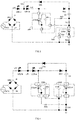
- FIG. 3 is a diagram of a linear constant current drive circuit according to Embodiment 1.
- the linear constant current drive circuit includes: a rectifier bridge DB3, an LED string, an energy storage capacitor C3, a first switch subcircuit SA3, a second switch subcircuit SB3, a first resistor R13, a second resistor R23, a third resistor R33, a first integrated circuit UA3, and a third switch subcircuit UB3.
- the first switch subcircuit SA3 is a first diode
- the second switch subcircuit SB3 is a second diode
- the third switch subcircuit UB3 is a second integrated circuit.
- the rectifier bridge DB3 has an input connected to a mains AC3, a first output end 13 being positive, and a second output end 113 grounded.
- the LED string is formed by connecting several LEDs, namely, an LED 13 to an LED n3 in series, and has a first end L31, a second end L32, and a tap end L3C, respectively defined as follows: One end of the LED 13 not connected to another LED is the first end L31, one end of the LED n3 not connected to another LED is the second end L32, and any tandem node or the first end of the LED string is the tap end L3C.
- the first integrated circuit UA3 and the second integrated circuit UB3 each have three pins, where a first pin is a current input end, a second pin is a chip ground, and a third pin is a current detection end.
- the first integrated circuit UA3 includes a first voltage controlled current source CCA3 and a first signal reference VA3, the first voltage controlled current source CCA3 includes two power ends and two control ends, and the two power ends are respectively connected to the first pin 1 and the third pin 3 of the first integrated circuit UA3.
- One control end of the first voltage controlled current source CCA3 is connected to a positive electrode of the first signal reference VA3, the other control end is connected to the third pin 3 of the first integrated circuit UA3, and a negative electrode of the first signal reference VA3 is connected to the second pin 2 of the first integrated circuit UA3.
- the second integrated circuit UB3 serving as the third switch subcircuit includes a second voltage controlled current source CCB3 and a second signal reference VB3, the second voltage controlled current source CCB3 includes two power ends and two control ends, and the two power ends are respectively connected to the first pin 4 and the third pin 6 of the second integrated circuit UB3.
- One control end of the second voltage controlled current source CCB3 is connected to a positive electrode of the second signal reference VB3, the other control end is connected to the third pin 6 of the second integrated circuit UB3, and a negative electrode of the second signal reference VB3 is connected to the second pin 5 of the second integrated circuit UB3.
- the first end L31 of the LED string is connected to the first output end 13 of the rectifier bridge DB3, and the second end L32 is connected to an anode of the first diode SA3, a cathode of the first diode SA3 is connected to one end of the energy storage capacitor C3, the other end of the energy storage capacitor C3 is connected to the first pin 1 of the first integrated circuit UA3 by using the first resistor R13, and the third pin 3 of the first integrated circuit UA3 is grounded by using the second resistor R23.
- the second pin 2 of the first integrated circuit UA3 and the second output end 113 of the rectifier bridge DB3 are grounded.
- An anode of the second diode SB3 is connected to a junction between the first diode SA3 and the energy storage capacitor C3, and a cathode of the second diode is connected to the tap end L3C of the LED string.
- the first pin 4 of the second integrated circuit UB3 is connected to the second end L32 of the LED string
- the second pin 5 of the second integrated circuit UB3 is connected to the first pin 1 of the first integrated circuit UA3
- the third pin 6 of the second integrated circuit UB3 is connected to a junction between the energy storage capacitor C3 and the first resistor R13 by using the third resistor R33.
- the energy storage capacitor C3, the second diode SB3, the LED n3 between the tap end and the second end of the LED string, the first pin 4 to the third pin 6 of the second integrated circuit UB3, and the third resistor R33 form an energy discharge branch.
- the output of the rectifier bridge DB3, the LED string, the first pin 4 to the third pin 6 of the second integrated circuit UB3, the third resistor R33, the first resistor R13, the first pin 1 to the third pin 2 of the first integrated circuit UA3, and the second resistor R23 form an LED direct branch.
- a work principle of the circuit is: When an output voltage amplitude of the rectifier bridge DB3 is greater than a sum of a voltage of the LED string and a voltage between the two ends of the energy storage capacitor C3, the first diode SA3 and the energy absorption branch are turned on; and the second diode SB3, the second integrated circuit UB3, the energy discharge branch, and the LED direct branch are turned off.
- the first diode SA3, the energy absorption branch, and the LED direct branch are turned off; and the second diode SB3, the second integrated circuit UB3, and the energy discharge branch are turned on.
- the linear constant current drive circuit in Embodiment 1 implements the beneficial effects of the present invention by using the two independent integrated circuits.
- FIG. 4 is a diagram of a linear constant current drive circuit according to Embodiment 2.
- the linear constant current drive circuit includes: a rectifier bridge DB4, an LED string, an energy storage capacitor C4, a first switch subcircuit SA4, a second switch subcircuit SB4, a fourth resistor R14, a fifth resistor R24, and a third integrated circuit UA4.
- the first switch subcircuit SA4 is a first diode
- the second switch subcircuit SB4 is a second diode
- a fourth integrated circuit UB4 serves as a third switch subcircuit.
- the rectifier bridge DB4 has an input connected to a mains AC4, a first output end 14 being positive, and a second output end 114 grounded.
- the LED string is formed by connecting several LEDs, namely, an LED 14 to an LED n4 in series, and has a first end L41, a second end L42, and a tap end L4C, respectively defined as follows: One end of the LED 14 not connected to another LED is the first end L41, one end of the LED n4 not connected to another LED is the second end L42, and any tandem node or the first end of the LED string is the tap end L4C.
- the third integrated circuit UA4 and the fourth integrated circuit UB4 each have three pins.
- the third integrated circuit UA4 includes a third voltage controlled current source CCA4 and a third signal reference VA4, the third voltage controlled current source CCA4 includes two power ends and two control ends, the two power ends of the third voltage controlled current source CCA4 are respectively connected to a first pin 12 and a third pin 14 of the third integrated circuit UA4, one of the two control ends of the third voltage controlled current source CCA4 is connected to a positive electrode of the third signal reference VA4, the other control end is connected to the third pin 14 of the third integrated circuit UA4, and a negative electrode of the third signal reference VA4 is connected to a second pin 13 of the third integrated circuit UA4.
- the fourth integrated circuit UB4 includes a fourth voltage controlled current source CCB4 and a fourth signal reference VB4, the fourth voltage controlled current source CCB4 includes two power ends and two control ends, the two power ends of the fourth voltage controlled current source CCB4 are respectively connected to a first pin 15 and a third pin 17 of the fourth integrated circuit UB4, one of the two control ends of the fourth voltage controlled current source CCB4 is connected to a positive electrode of the fourth signal reference VB4, the other control end is connected to the third pin 17 of the fourth integrated circuit UB4, and a negative electrode of the fourth signal reference VB4 is connected to a second pin 16 of the fourth integrated circuit UB4.
- the first end L41 of the LED string is connected to the first output end 14 of the rectifier bridge DB4, and the second end L42 is connected to an anode of the first diode SA4, a cathode of the first diode SA4 is connected to one end of the energy storage capacitor C4, the other end of the energy storage capacitor C4 is connected to the first pin 12 of the third integrated circuit UA4, and the third pin 14 of the third integrated circuit UA4 is grounded by using the fourth resistor R14.
- the first pin 15 of the fourth integrated circuit UB4 is connected to the second end L42 of the LED string, and the third pin 17 of the fourth integrated circuit UB4 is connected to the third pin 14 of the third integrated circuit UA4 by using the fifth resistor R24.
- the second pin 13 of the third integrated circuit UA4 and the second pin 16 of the fourth integrated circuit UB4 are both grounded.
- An anode of the second diode SB4 is connected to a junction between the first diode SA4 and the energy storage capacitor C4, and a cathode of the second diode is connected to the tap end L4C of the LED string.
- the energy storage capacitor C4, the second diode SB4, the LED n4 between the tap end L4C and the second end L42 of the LED string, the first pin 15 to the third pin 17 of the fourth integrated circuit UB4, the fifth resistor R24, and the third pin 14 to the first pin 12 of the third integrated circuit UA4 form an energy discharge branch.
- the output of the rectifier bridge DB4, the LED string, the first pin 15 to the third pin 17 of the fourth integrated circuit UB4, the fifth resistor R24, and the fourth resistor R14 form an LED direct branch.
- a work principle of the circuit is: When an output voltage amplitude of the rectifier bridge DB4 is greater than a sum of a voltage of the LED string and a voltage between the two ends of the energy storage capacitor C4, the first diode SA4 and the energy absorption branch are turned on; and the second diode SB4, the fourth integrated circuit UB4, the energy discharge branch, and the LED direct branch are turned off.
- the first diode SA4, the energy absorption branch, and the LED direct branch are turned off; and the second diode SB4, the fourth integrated circuit UB4, and the energy discharge branch are turned on.
- the third integrated circuit UA4 and the fourth integrated circuit UB4 in this embodiment use a same ground level, and are conveniently integrated into one encapsulation to implement the beneficial effects of the present invention.
- a switch current source may be connected in parallel between the two ends of the output of the rectifier bridge.
- the switch current source is connected in parallel between the two ends of the output of the rectifier bridge, is turned off when either of the energy absorption branch and the LED direct branch is turned on, and is turned on when neither of the energy absorption branch and the LED direct branch is turned on.
- a beneficial effect of the present invention is: A current of the mains is maintained to be continuous, so that the present invention is better compatible with a power supplying occasion on which a conventional silicon-controlled dimmer is used.
Landscapes
- Engineering & Computer Science (AREA)
- Power Engineering (AREA)
- Circuit Arrangement For Electric Light Sources In General (AREA)
Applications Claiming Priority (2)
| Application Number | Priority Date | Filing Date | Title |
|---|---|---|---|
| CN201610956917.8A CN106413192B (zh) | 2016-10-25 | 2016-10-25 | 一种线性恒流驱动电路 |
| PCT/CN2017/105342 WO2018077021A1 (fr) | 2016-10-25 | 2017-10-09 | Circuit pilote à courant constant linéaire |
Publications (2)
| Publication Number | Publication Date |
|---|---|
| EP3534677A1 true EP3534677A1 (fr) | 2019-09-04 |
| EP3534677A4 EP3534677A4 (fr) | 2019-11-13 |
Family
ID=58015003
Family Applications (1)
| Application Number | Title | Priority Date | Filing Date |
|---|---|---|---|
| EP17864992.7A Withdrawn EP3534677A4 (fr) | 2016-10-25 | 2017-10-09 | Circuit pilote à courant constant linéaire |
Country Status (4)
| Country | Link |
|---|---|
| US (1) | US10687401B2 (fr) |
| EP (1) | EP3534677A4 (fr) |
| CN (1) | CN106413192B (fr) |
| WO (1) | WO2018077021A1 (fr) |
Families Citing this family (5)
| Publication number | Priority date | Publication date | Assignee | Title |
|---|---|---|---|---|
| CN106413192B (zh) | 2016-10-25 | 2020-12-15 | 上海路傲电子科技有限公司 | 一种线性恒流驱动电路 |
| CN106961768B (zh) | 2017-04-28 | 2019-02-19 | 南京微客力科技有限公司 | 一种主动式填谷电路模式的led线性恒流驱动电路 |
| CN107454710B (zh) * | 2017-05-31 | 2019-01-18 | 上海路傲电子科技有限公司 | 一种线性恒流驱动电路 |
| CN111148319A (zh) * | 2019-12-30 | 2020-05-12 | 安徽展晖电子科技有限公司 | 一种双电压模式led照明线性恒流驱动电路 |
| WO2024065669A1 (fr) * | 2022-09-30 | 2024-04-04 | 上海晶丰明源半导体股份有限公司 | Circuit d'attaque de del à élimination de papillotement et son procédé de commande d'attaque |
Family Cites Families (12)
| Publication number | Priority date | Publication date | Assignee | Title |
|---|---|---|---|---|
| CN101795515B (zh) * | 2010-01-05 | 2012-12-12 | 艾迪光电(杭州)有限公司 | 启动过冲电流抑制电路 |
| KR101302182B1 (ko) * | 2013-02-14 | 2013-08-30 | 장우준 | 발광다이오드의 점멸주파수를 변환시키는 전원공급회로 |
| JP5958407B2 (ja) * | 2013-04-12 | 2016-08-02 | 株式会社デンソー | Led駆動装置 |
| CN103269537B (zh) | 2013-05-28 | 2015-04-01 | 上海路千电子科技有限公司 | 一种限流供电电路及其控制方法和限流供电方法 |
| CN103313489B (zh) | 2013-07-03 | 2016-04-27 | 上海路千电子科技有限公司 | 一种组合线性恒流源以及led驱动电路 |
| CN104507227B (zh) * | 2014-12-17 | 2016-08-17 | 东莞市纳川盈海照明有限公司 | 无变压器的恒流电源电路 |
| CN204377201U (zh) * | 2015-01-09 | 2015-06-03 | 嘉兴市光泰照明有限公司 | 一种led恒流驱动电路及led汽车照明装置 |
| US10044289B2 (en) * | 2015-04-08 | 2018-08-07 | Citizen Watch Co., Ltd. | LED drive circuit including a plurality of LEDs connected in series |
| CN104936356B (zh) * | 2015-06-29 | 2018-10-23 | 上海路傲电子科技有限公司 | 线性恒流驱动电路 |
| CN205648122U (zh) * | 2016-05-26 | 2016-10-12 | 深圳市明微电子股份有限公司 | 一种基于可控硅调光器的线性恒流led驱动电路 |
| CN106413192B (zh) | 2016-10-25 | 2020-12-15 | 上海路傲电子科技有限公司 | 一种线性恒流驱动电路 |
| CN206118126U (zh) * | 2016-10-25 | 2017-04-19 | 上海路傲电子科技有限公司 | 一种新型线性恒流驱动电路 |
-
2016
- 2016-10-25 CN CN201610956917.8A patent/CN106413192B/zh active Active
-
2017
- 2017-10-09 US US16/340,569 patent/US10687401B2/en active Active
- 2017-10-09 EP EP17864992.7A patent/EP3534677A4/fr not_active Withdrawn
- 2017-10-09 WO PCT/CN2017/105342 patent/WO2018077021A1/fr not_active Ceased
Also Published As
| Publication number | Publication date |
|---|---|
| CN106413192A (zh) | 2017-02-15 |
| CN106413192B (zh) | 2020-12-15 |
| US20190239299A1 (en) | 2019-08-01 |
| US10687401B2 (en) | 2020-06-16 |
| WO2018077021A1 (fr) | 2018-05-03 |
| EP3534677A4 (fr) | 2019-11-13 |
Similar Documents
| Publication | Publication Date | Title |
|---|---|---|
| EP3534677A1 (fr) | Circuit pilote à courant constant linéaire | |
| US9101018B2 (en) | Apparatuses for bleeding current from a transformer of a solid-state light emitting diode | |
| CN103648219B (zh) | 一种led开关恒流驱动电路 | |
| CN104661392B (zh) | 一种led开关恒流驱动电路 | |
| CN102474953A (zh) | 发光装置的调光器 | |
| CN103491682A (zh) | 一种控制峰值电流的线性开关恒流led驱动电路 | |
| CN102740555A (zh) | 用于固态光源的点亮装置和包括该点亮装置的照明设备 | |
| CN101925230A (zh) | 高效率低功耗低成本led驱动电源 | |
| US20140285102A1 (en) | High power factor, electrolytic capacitor-less driver circuit for light-emitting diode lamps | |
| CN104780694B (zh) | 一种led触控调光恒流驱动电源 | |
| CN104540294B (zh) | 一种实现无极调光的自激式led转换装置及控制方法 | |
| CN206118126U (zh) | 一种新型线性恒流驱动电路 | |
| CN103945616A (zh) | 一种灯具及其led驱动装置 | |
| CN203504839U (zh) | 一种采用初级检测和调控的led灯驱动电源 | |
| CN203934041U (zh) | 一种灯具及其led驱动装置 | |
| CN205017631U (zh) | 基于ZigBee技术的智能路灯控制系统 | |
| CN203327325U (zh) | 一种led恒流分段调光电路 | |
| JP2014127714A (ja) | 発光ダイオード駆動装置 | |
| CN204598401U (zh) | 一种led触控调光电源 | |
| US11445586B2 (en) | Adaptive power balancing in LED lamps | |
| CN206260105U (zh) | 一种将高压脉冲信号转换为低压脉宽信号的电路 | |
| CN105142266A (zh) | 一种可调光led驱动电路 | |
| CN204795799U (zh) | 一种可调光led驱动电路 | |
| CN204539573U (zh) | 一种led调光调色电路 | |
| CN103917020B (zh) | 一种led驱动电路 |
Legal Events
| Date | Code | Title | Description |
|---|---|---|---|
| PUAI | Public reference made under article 153(3) epc to a published international application that has entered the european phase |
Free format text: ORIGINAL CODE: 0009012 |
|
| 17P | Request for examination filed |
Effective date: 20190522 |
|
| AK | Designated contracting states |
Kind code of ref document: A1 Designated state(s): AL AT BE BG CH CY CZ DE DK EE ES FI FR GB GR HR HU IE IS IT LI LT LU LV MC MK MT NL NO PL PT RO RS SE SI SK SM TR |
|
| AX | Request for extension of the european patent |
Extension state: BA ME |
|
| A4 | Supplementary search report drawn up and despatched |
Effective date: 20191014 |
|
| RIC1 | Information provided on ipc code assigned before grant |
Ipc: H05B 33/08 20060101AFI20191008BHEP |
|
| DAV | Request for validation of the european patent (deleted) | ||
| DAX | Request for extension of the european patent (deleted) | ||
| STAA | Information on the status of an ep patent application or granted ep patent |
Free format text: STATUS: THE APPLICATION IS DEEMED TO BE WITHDRAWN |
|
| 18D | Application deemed to be withdrawn |
Effective date: 20200603 |