EP3534970B1 - Dekontaminationsvorrichtung und verfahren - Google Patents
Dekontaminationsvorrichtung und verfahren Download PDFInfo
- Publication number
- EP3534970B1 EP3534970B1 EP17803823.8A EP17803823A EP3534970B1 EP 3534970 B1 EP3534970 B1 EP 3534970B1 EP 17803823 A EP17803823 A EP 17803823A EP 3534970 B1 EP3534970 B1 EP 3534970B1
- Authority
- EP
- European Patent Office
- Prior art keywords
- tube
- ultraviolet radiation
- cavity
- subjecting
- neck
- Prior art date
- Legal status (The legal status is an assumption and is not a legal conclusion. Google has not performed a legal analysis and makes no representation as to the accuracy of the status listed.)
- Active
Links
Images


Classifications
-
- A—HUMAN NECESSITIES
- A61—MEDICAL OR VETERINARY SCIENCE; HYGIENE
- A61L—METHODS OR APPARATUS FOR STERILISING MATERIALS OR OBJECTS IN GENERAL; DISINFECTION, STERILISATION OR DEODORISATION OF AIR; CHEMICAL ASPECTS OF BANDAGES, DRESSINGS, ABSORBENT PADS OR SURGICAL ARTICLES; MATERIALS FOR BANDAGES, DRESSINGS, ABSORBENT PADS OR SURGICAL ARTICLES
- A61L2/00—Disinfection or sterilisation of materials or objects, in general; Accessories therefor
- A61L2/02—Disinfection or sterilisation of materials or objects, in general; Accessories therefor using physical processes
- A61L2/08—Radiation
- A61L2/10—Ultraviolet [UV] radiation
-
- A—HUMAN NECESSITIES
- A61—MEDICAL OR VETERINARY SCIENCE; HYGIENE
- A61L—METHODS OR APPARATUS FOR STERILISING MATERIALS OR OBJECTS IN GENERAL; DISINFECTION, STERILISATION OR DEODORISATION OF AIR; CHEMICAL ASPECTS OF BANDAGES, DRESSINGS, ABSORBENT PADS OR SURGICAL ARTICLES; MATERIALS FOR BANDAGES, DRESSINGS, ABSORBENT PADS OR SURGICAL ARTICLES
- A61L2/00—Disinfection or sterilisation of materials or objects, in general; Accessories therefor
- A61L2/02—Disinfection or sterilisation of materials or objects, in general; Accessories therefor using physical processes
- A61L2/08—Radiation
- A61L2/085—Infrared radiation
-
- B—PERFORMING OPERATIONS; TRANSPORTING
- B29—WORKING OF PLASTICS; WORKING OF SUBSTANCES IN A PLASTIC STATE IN GENERAL
- B29C—SHAPING OR JOINING OF PLASTICS; SHAPING OF MATERIAL IN A PLASTIC STATE, NOT OTHERWISE PROVIDED FOR; AFTER-TREATMENT OF THE SHAPED PRODUCTS, e.g. REPAIRING
- B29C49/00—Blow-moulding, i.e. blowing a preform or parison to a desired shape within a mould; Apparatus therefor
- B29C49/02—Combined blow-moulding and manufacture of the preform or the parison
- B29C49/06—Injection blow-moulding
-
- B—PERFORMING OPERATIONS; TRANSPORTING
- B67—OPENING, CLOSING OR CLEANING BOTTLES, JARS OR SIMILAR CONTAINERS; LIQUID HANDLING
- B67B—APPLYING CLOSURE MEMBERS TO BOTTLES JARS, OR SIMILAR CONTAINERS; OPENING CLOSED CONTAINERS
- B67B3/00—Closing bottles, jars or similar containers by applying caps
- B67B3/003—Pretreatment of caps, e.g. cleaning, steaming, heating or sterilizing
-
- A—HUMAN NECESSITIES
- A61—MEDICAL OR VETERINARY SCIENCE; HYGIENE
- A61L—METHODS OR APPARATUS FOR STERILISING MATERIALS OR OBJECTS IN GENERAL; DISINFECTION, STERILISATION OR DEODORISATION OF AIR; CHEMICAL ASPECTS OF BANDAGES, DRESSINGS, ABSORBENT PADS OR SURGICAL ARTICLES; MATERIALS FOR BANDAGES, DRESSINGS, ABSORBENT PADS OR SURGICAL ARTICLES
- A61L2103/00—Materials or objects being the target of disinfection or sterilisation
- A61L2103/23—Containers other than laboratory or medical, e.g. bottles or mail
-
- A—HUMAN NECESSITIES
- A61—MEDICAL OR VETERINARY SCIENCE; HYGIENE
- A61L—METHODS OR APPARATUS FOR STERILISING MATERIALS OR OBJECTS IN GENERAL; DISINFECTION, STERILISATION OR DEODORISATION OF AIR; CHEMICAL ASPECTS OF BANDAGES, DRESSINGS, ABSORBENT PADS OR SURGICAL ARTICLES; MATERIALS FOR BANDAGES, DRESSINGS, ABSORBENT PADS OR SURGICAL ARTICLES
- A61L2202/00—Aspects relating to methods or apparatus for disinfecting or sterilising materials or objects
- A61L2202/10—Apparatus features
- A61L2202/11—Apparatus for generating biocidal substances, e.g. vaporisers, UV lamps
-
- B—PERFORMING OPERATIONS; TRANSPORTING
- B29—WORKING OF PLASTICS; WORKING OF SUBSTANCES IN A PLASTIC STATE IN GENERAL
- B29B—PREPARATION OR PRETREATMENT OF THE MATERIAL TO BE SHAPED; MAKING GRANULES OR PREFORMS; RECOVERY OF PLASTICS OR OTHER CONSTITUENTS OF WASTE MATERIAL CONTAINING PLASTICS
- B29B13/00—Conditioning or physical treatment of the material to be shaped
- B29B13/08—Conditioning or physical treatment of the material to be shaped by using wave energy or particle radiation
-
- B—PERFORMING OPERATIONS; TRANSPORTING
- B29—WORKING OF PLASTICS; WORKING OF SUBSTANCES IN A PLASTIC STATE IN GENERAL
- B29C—SHAPING OR JOINING OF PLASTICS; SHAPING OF MATERIAL IN A PLASTIC STATE, NOT OTHERWISE PROVIDED FOR; AFTER-TREATMENT OF THE SHAPED PRODUCTS, e.g. REPAIRING
- B29C49/00—Blow-moulding, i.e. blowing a preform or parison to a desired shape within a mould; Apparatus therefor
- B29C49/02—Combined blow-moulding and manufacture of the preform or the parison
- B29C2049/023—Combined blow-moulding and manufacture of the preform or the parison using inherent heat of the preform, i.e. 1 step blow moulding
-
- B—PERFORMING OPERATIONS; TRANSPORTING
- B29—WORKING OF PLASTICS; WORKING OF SUBSTANCES IN A PLASTIC STATE IN GENERAL
- B29C—SHAPING OR JOINING OF PLASTICS; SHAPING OF MATERIAL IN A PLASTIC STATE, NOT OTHERWISE PROVIDED FOR; AFTER-TREATMENT OF THE SHAPED PRODUCTS, e.g. REPAIRING
- B29C49/00—Blow-moulding, i.e. blowing a preform or parison to a desired shape within a mould; Apparatus therefor
- B29C49/42—Component parts, details or accessories; Auxiliary operations
- B29C49/46—Component parts, details or accessories; Auxiliary operations characterised by using particular environment or blow fluids other than air
- B29C2049/4673—Environments
-
- B—PERFORMING OPERATIONS; TRANSPORTING
- B29—WORKING OF PLASTICS; WORKING OF SUBSTANCES IN A PLASTIC STATE IN GENERAL
- B29C—SHAPING OR JOINING OF PLASTICS; SHAPING OF MATERIAL IN A PLASTIC STATE, NOT OTHERWISE PROVIDED FOR; AFTER-TREATMENT OF THE SHAPED PRODUCTS, e.g. REPAIRING
- B29C49/00—Blow-moulding, i.e. blowing a preform or parison to a desired shape within a mould; Apparatus therefor
- B29C49/42—Component parts, details or accessories; Auxiliary operations
- B29C49/4252—Auxiliary operations prior to the blow-moulding operation not otherwise provided for
-
- B—PERFORMING OPERATIONS; TRANSPORTING
- B29—WORKING OF PLASTICS; WORKING OF SUBSTANCES IN A PLASTIC STATE IN GENERAL
- B29C—SHAPING OR JOINING OF PLASTICS; SHAPING OF MATERIAL IN A PLASTIC STATE, NOT OTHERWISE PROVIDED FOR; AFTER-TREATMENT OF THE SHAPED PRODUCTS, e.g. REPAIRING
- B29C49/00—Blow-moulding, i.e. blowing a preform or parison to a desired shape within a mould; Apparatus therefor
- B29C49/42—Component parts, details or accessories; Auxiliary operations
- B29C49/4268—Auxiliary operations during the blow-moulding operation
-
- B—PERFORMING OPERATIONS; TRANSPORTING
- B29—WORKING OF PLASTICS; WORKING OF SUBSTANCES IN A PLASTIC STATE IN GENERAL
- B29K—INDEXING SCHEME ASSOCIATED WITH SUBCLASSES B29B, B29C OR B29D, RELATING TO MOULDING MATERIALS OR TO MATERIALS FOR MOULDS, REINFORCEMENTS, FILLERS OR PREFORMED PARTS, e.g. INSERTS
- B29K2667/00—Use of polyesters or derivatives thereof for preformed parts, e.g. for inserts
- B29K2667/003—PET, i.e. poylethylene terephthalate
-
- B—PERFORMING OPERATIONS; TRANSPORTING
- B67—OPENING, CLOSING OR CLEANING BOTTLES, JARS OR SIMILAR CONTAINERS; LIQUID HANDLING
- B67C—CLEANING, FILLING WITH LIQUIDS OR SEMILIQUIDS, OR EMPTYING, OF BOTTLES, JARS, CANS, CASKS, BARRELS, OR SIMILAR CONTAINERS, NOT OTHERWISE PROVIDED FOR; FUNNELS
- B67C3/00—Bottling liquids or semiliquids; Filling jars or cans with liquids or semiliquids using bottling or like apparatus; Filling casks or barrels with liquids or semiliquids
- B67C3/02—Bottling liquids or semiliquids; Filling jars or cans with liquids or semiliquids using bottling or like apparatus
- B67C3/22—Details
- B67C2003/227—Additional apparatus related to blow-moulding of the containers, e.g. a complete production line forming filled containers from preforms
-
- B—PERFORMING OPERATIONS; TRANSPORTING
- B67—OPENING, CLOSING OR CLEANING BOTTLES, JARS OR SIMILAR CONTAINERS; LIQUID HANDLING
- B67C—CLEANING, FILLING WITH LIQUIDS OR SEMILIQUIDS, OR EMPTYING, OF BOTTLES, JARS, CANS, CASKS, BARRELS, OR SIMILAR CONTAINERS, NOT OTHERWISE PROVIDED FOR; FUNNELS
- B67C3/00—Bottling liquids or semiliquids; Filling jars or cans with liquids or semiliquids using bottling or like apparatus; Filling casks or barrels with liquids or semiliquids
- B67C3/02—Bottling liquids or semiliquids; Filling jars or cans with liquids or semiliquids using bottling or like apparatus
- B67C3/22—Details
- B67C3/26—Filling-heads; Means for engaging filling-heads with bottle necks
- B67C2003/2688—Means for filling containers in defined atmospheric conditions
Definitions
- the present invention relates to a decontamination device and method.
- Such a device allows a user to decontaminate an object such as a plastic preform on a production line and filling of a plastic bottle or container.
- the field of the invention is more particularly that of microbiological decontamination.
- WO 2013/092879 describes an assembly consisting of a decontamination device and at least one preform, an installation and a method for manufacturing a sterile container.
- EP2094312 describes an oven and an installation for the manufacture of sterile containers from decontaminated thermoplastic preforms.
- the document US2014/0265039 describes a method in which means for emitting ultraviolet radiation are introduced inside the preform to decontaminate it. Also known are the documents EP 2 138 298 A2 , EP 2 961 437 B1 , US 2012/273693 A1 , JP H11 263322 A and EP 1 918 208 A1 .
- the aim of the present invention is to resolve at least one of these drawbacks while continuing to provide a good level of decontamination of the internal surface of the preform compatible for example with the food industry, in particular with “ultra-clean” lines having an intermediate level of asepsis.
- the second end of the tube When subjecting the tube to ultraviolet radiation, the second end of the tube is not in the cavity.
- the tube body When subjecting the tube to ultraviolet radiation, the tube body may not be in the cavity.
- All parts of the tube preferably have a temperature greater than or equal to 85°C when the tube is subjected to ultraviolet radiation.
- the radiation emitting means When subjecting the tube to ultraviolet radiation, the radiation emitting means may not be inserted inside the tube.
- the method according to the invention preferably does not include any insertion of any other means of emitting radiation inside the tube.
- the tube can be a plastic tube.
- the method according to the invention may comprise subjecting the cap to ultraviolet radiation before fixing it to the tube.
- the method according to the invention may include no chemical decontamination of the tube.
- the initial temperature rise can be obtained by passing the tube through an oven and/or by subjecting the tube to an infrared lamp.
- the initial temperature rise preferably raises all parts of the tube to a temperature greater than or equal to 90°C.
- a device for decontaminating a tube as defined in claim 14.
- the moving means and the cavity may be arranged together so that the body of the tube is not in the cavity when the tube passes through the cavity.
- the heating means, the cavity and the moving means connecting the heating means to the cavity may be arranged so that all parts of the tube have a temperature greater than or equal to 85°C when the tube passes through the cavity.
- the radiation emitting means may not be arranged to be inserted inside the tube when the tube passes through the cavity.
- the device according to the invention may not comprise any other means of emitting radiation arranged to be inserted inside the tube during the passage of the tube at the level of the cavity.
- the device according to the invention may comprise means for subjecting the cap to ultraviolet radiation before fixing it to the tube by the fixing means.
- the device according to the invention may include no means of chemical decontamination of the tube.
- the heating means may include an oven and/or an infrared lamp.
- the heating means may be arranged to raise all parts of the tube to a temperature greater than or equal to 90°C.
- variants of the invention comprising only a selection of features described or illustrated subsequently isolated from the other features described or illustrated (even if this selection is isolated within a sentence comprising these other features), if this selection of features is sufficient to confer a technical advantage or to differentiate the invention compared to the state of the prior art.
- This selection comprises at least one preferably functional feature without structural details, and/or with only a part of the structural details if this part alone is sufficient to confer a technical advantage or to differentiate the invention compared to the state of the prior art.
- the device 1 for microbiological decontamination of a tube 2 comprises means 13 for moving, along a decontamination path in a direction of travel 14, a tube 2.
- the device 1 comprises initial heating means 8, arranged to raise the temperature of the tube 2 on the decontamination path.
- the heating means 8 include an oven, more precisely an oven with an infrared halogen lamp of 1000 Watts or even several tens of kilo Watts for a greater flow rate.
- the heating means 8 are arranged to raise all parts of the tube 2 to a temperature greater than or equal to 90°C, preferably greater than or equal to 100°C, preferably greater than or equal to 115°C, preferably greater than or equal to 142°C.
- These means for subjecting the tube 2 to ultraviolet radiation comprise emission means 5 arranged to emit the ultraviolet radiation.
- the ultraviolet radiation has at least one wavelength between 10 nm and 380 nm, preferably between 180 nm and 380 nm.
- the emission means 5 are further arranged to emit, simultaneously with the ultraviolet radiation, at least one wavelength between 380 and 1100 nm, which is advantageous for example against mold.
- These emission means 5 typically comprise at least one UV lamp.
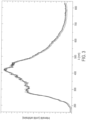
- Each UV lamp extends in the direction of travel 14, and comprises for example a Xenon gas ionization UV lamp whose intensity profile (in arbitrary units, the intensity depending on the supply voltage) is illustrated in the figure 3 .
- a supply voltage of 2100V corresponds to a total dissipated energy (light, heat, etc.) per pulse of 145 Joules, or approximately 72.5 joules of light energy emitted by the lamp;
- a supply voltage of 2500V corresponds to a total dissipated energy (light, heat, etc.) per pulse of 206 Joules, or approximately 103 Joules of light energy emitted by the lamp.
- Each UV lamp is in contact with a cooling liquid 15 (typically deionized water typically maintained between 10°C and 35°C) located between the UV lamp and a quartz window 16.
- a cooling liquid 15 typically deionized water typically maintained between 10°C and 35°C
- the means for subjecting the tube 2 to ultraviolet radiation further comprise a cavity 4 located on the decontamination path downstream of the heating means 8 relative to the direction of travel 14.
- the emission means 5 are arranged inside the cavity 4.
- cavity 4 The interior of cavity 4 is delimited by a reflective surface in Aluminum, made in one piece in EN AW 5754.
- the radiation emission means 5 are not arranged to be inserted inside the tube 2 when the tube 2 passes through the cavity 4. This makes it possible not to waste time inserting and removing the means 5 inside the tube 2 and allows a high speed of the method according to the invention, typically at least 25,000 decontaminated tubes per hour (typically between 5,000 and 100,000 decontaminated tubes per hour). This also makes it possible to avoid breaking the means 5 inside the tube 2 and leaving dangerous debris there, particularly in the context of the agri-food industry.
- the device 1 does not include any other means of emitting radiation arranged to be inserted inside the tube 2 during the passage of the tube 2 at the level of the cavity 4.
- ultraviolet radiation is a flash of light (typically a flash of white light) comprising UV and further comprising at least one other wavelength between 400 and 700 nm, i.e. “visible” light.
- the heating means 8 are used both for the decontamination of the tube 2 and to make possible the modification of the shape of the tube 2.
- the device 1 does not include means for raising the temperature of the tube 2 along the decontamination path between the cavity 4 and the means 9 for modifying the shape of the tube 2, more generally between the cavity 4 and the means 10 for filling the tube 2, more generally between the cavity 4 and the means 11 for fixing the stopper.
- the device 1 comprises means 12 for subjecting the stopper to ultraviolet radiation before its fixing on the tube 2 by the fixing means 11, of the same type as those described for the means 5 and the cavity 4.
- the device 1 does not include any means for chemically decontaminating the tube.
- the device 1 does not include any means for placing the tube 2 in contact with a liquid or product other than that used by the filling means 10 to fill the tube and kept inside the tube 2 after fixing the cap.
- the UV lamps are separated from tube 2 by quartz blades 17, 18 arranged within cavity 4.
- the second end 6 of the tube When subjecting the tube 2 to ultraviolet radiation, the second end 6 of the tube is not in the cavity 4.
- the radiation emitting means 5 When subjecting the tube 2 to ultraviolet radiation, the radiation emitting means 5 are not inserted inside the tube 2. Generally, there is no insertion of any other radiation emitting means inside the tube 2.
- Ultraviolet radiation is pulsed ultraviolet light as previously described.
- the principle of decontamination according to this embodiment is compatible with the variant in which the tube 2 can be of any type (glass, polylactic acid (PLA), etc.)
- the light decontamination treatment is immediate, due to the use of pulsed technology, emitting white light rich in UV, with very high power.
- Type of decontamination Decontamination measurement (in log) A) Heating alone by heating means 8 to 115°C (temperature of tube 2 at the outlet of oven 8) 2.1 B) Heating alone by heating means 8 at 142°C (temperature of tube 2 at the outlet of oven 8) 2.2 C) UV decontamination alone by means 4, 5; 1 flash per UV lamp per tube 2 1.9 D) UV decontamination alone by means 4, 5; 2 flashes per UV lamp per tube 2 2.0 Heating case A) + UV decontamination D) 4.2 Heating case B) + UV decontamination C) 4.5 Heating case B) + UV decontamination D) 4.4
- Decontaminations are given in log (1 log of decontamination corresponds to a division by ten of the number of germs; 3 log of decontamination corresponds to a division by a thousand of the number of germs; 4 log of decontamination corresponds to a division by ten thousand of the number of germs; etc.).
- the number of remaining germs is counted according to classic microbiology techniques (method by inclusion in a culture medium and filtration).
- Tests show that the invention makes it possible to obtain a decontamination level greater than 4.2 log on the outer collar 3b (less critical surface).
- all parts of the tube except the neck preferably have a temperature greater than or equal to 85°C when subjecting the tube to ultraviolet radiation, preferably greater than or equal to 90°C, preferably greater than or equal to 100°C, preferably greater than or equal to 115°C, preferably greater than or equal to 142°C.
- the heating means, the cavity and the displacement means connecting the heating means to the cavity can be arranged so that all parts of the tube except the neck have a temperature greater than or equal to 85°C when the tube passes through the cavity, preferably greater than or equal to 90°C, preferably greater than or equal to 100°C, preferably greater than or equal to 115°C, preferably greater than or equal to 142°C.
- the neck typically includes parts ensuring the sealing of the future bottle, this can in fact prevent it from being deformed by heat.
Landscapes
- Health & Medical Sciences (AREA)
- Engineering & Computer Science (AREA)
- Mechanical Engineering (AREA)
- Epidemiology (AREA)
- Life Sciences & Earth Sciences (AREA)
- Animal Behavior & Ethology (AREA)
- General Health & Medical Sciences (AREA)
- Public Health (AREA)
- Veterinary Medicine (AREA)
- Manufacturing & Machinery (AREA)
- Apparatus For Disinfection Or Sterilisation (AREA)
Claims (14)
- Verfahren zur Dekontamination eines Röhrchens (2), dessen erstes offenes Ende (3) einen Innenhals (3a) zur Innenseite des Röhrchens und einen Außenhals (3b) zur Außenseite des Röhrchens hin bildet, wobei das Verfahren umfasst:- eine anfängliche Erhöhung der Röhrchentemperatur, dannAussetzen des Röhrchens gegenüber einer ultravioletten Strahlung, umfassend eine Emission der ultravioletten Strahlung durch eine Strahlung emittierende Einrichtung (5), und Aussetzen des Inneren des Röhrchens, des Außenhalses und des Innenhalses gegenüber der ultravioletten Strahlung, während das erste Ende (3) in das Innere eines Hohlraums (4) eingeführt wird, der so ausgestaltet ist, dass er die von der Emissionseinrichtung emittierte ultraviolette Strahlung reflektiert und diese ultraviolette Strahlung durch das erste Ende ins Innere des Röhrchens, zum Außenhals des Röhrchens und zum Innenhals des Röhrchens (2) lenkt; wobei das Röhrchen (2) umfasst:- ein zweites Ende (6), das einen Boden des Röhrchens bildet, und- einen Körper (7), der sich zwischen dem ersten Ende und dem zweiten Ende erstreckt;so dass sich das zweite Ende des Röhrchens nicht im Hohlraum befindet, wenn das Röhrchen ultravioletter Strahlung ausgesetzt wird.
- Verfahren nach Anspruch 1, dadurch gekennzeichnet, dass, wenn das Röhrchen ultravioletter Strahlung ausgesetzt wird, der Röhrchenkörper sich nicht im Hohlraum befindet.
- Verfahren nach einem der vorhergehenden Ansprüche,
dadurch gekennzeichnet, dass alle Teile des Röhrchens oder alle Teile des Röhrchens mit Ausnahme des Halses eine Temperatur von über oder gleich 85 °C aufweisen, wenn das Röhrchen ultravioletter Strahlung ausgesetzt wird. - Verfahren nach einem der vorhergehenden Ansprüche,
dadurch gekennzeichnet, dass, wenn das Röhrchen ultravioletter Strahlung ausgesetzt wird, die Strahlungsemissionseinrichtung nicht in das Innere des Röhrchens eingeführt wird. - Verfahren nach Anspruch 4, dadurch gekennzeichnet, dass es nicht das Einführen einer anderen Strahlungsemissionseinrichtung in das Röhrchen umfasst.
- Verfahren nach einem der vorhergehenden Ansprüche,
dadurch gekennzeichnet, dass die ultraviolette Strahlung mindestens eine UV-Wellenlänge zwischen 180 nm und 380 nm umfasst und Folgendes aufweist:- eine Impulsdauer von weniger als 500 µs und/oder- eine Lichtenergie pro Impuls von mindestens 70 Joule und/oder- eine Impulsfrequenz von mindestens 0,5 Hz oder eine Impulserzeugung, die in Abhängigkeit von der Geschwindigkeit gesteuert wird, mit der die zu dekontaminierenden Röhrchen vor der Emissionseinrichtung (5) und/oder im Hohlraum (4) passieren. - Verfahren nach einem der vorstehenden Ansprüche,
dadurch gekennzeichnet, dass das Röhrchen ein Röhrchen aus Kunststoff ist. - Verfahren nach einem der vorhergehenden Ansprüche,
dadurch gekennzeichnet, dass es, nachdem das Röhrchen der ultravioletten Strahlung ausgesetzt wurde, mindestens einen der folgenden Schritte vorzugsweise in der folgenden Reihenfolge umfasst:- Ändern der Form des Röhrchens und/oder- Befüllen des Röhrchens und/oder- Befestigen eines Verschlusses auf dem Röhrchen, der den Außenhals berührt. - Verfahren nach Anspruch 8, dadurch gekennzeichnet, dass es keine Erhöhung der Röhrchentemperatur umfasst:- zwischen dem Aussetzen des Röhrchens gegenüber der ultravioletten Strahlung und der Änderung der Form des Röhrchens und/oder- zwischen dem Aussetzen des Röhrchens gegenüber der ultravioletten Strahlung und dem Befüllen des Röhrchens und/oder- zwischen dem Aussetzen des Röhrchens gegenüber der ultravioletten Strahlung und dem Befestigen des Verschlusses.
- Verfahren nach Anspruch 8 oder 9, dadurch gekennzeichnet, dass es das Aussetzen des Verschlusses gegenüber einer ultravioletten Strahlung umfasst, bevor er auf dem Röhrchen befestigt wird.
- Verfahren nach einem der vorstehenden Ansprüche,
dadurch gekennzeichnet, dass es keine chemische Dekontamination des Röhrchens umfasst. - Verfahren nach einem der vorhergehenden Ansprüche,
dadurch gekennzeichnet, dass die anfängliche Temperaturerhöhung dadurch erreicht wird, dass das Röhrchen einen Ofen durchläuft und/oder dass das Röhrchen einer Infrarotlampe ausgesetzt wird. - Verfahren nach einem der vorhergehenden Ansprüche,
dadurch gekennzeichnet, dass durch die anfängliche Temperaturerhöhung alle Teile des Röhrchens auf eine Temperatur von mindestens 90 °C gebracht werden. - Vorrichtung (1) zur Dekontamination eines Röhrchens (2), umfassend:- eine Einrichtung (13) zum Bewegen eines Röhrchens, dessen erstes offenes Ende (3) einen Innenhals (3a) zur Innenseite des Röhrchens und einen Außenhals (3b) zur Außenseite des Röhrchens hin bildet, entlang eines Dekontaminationswegs in einer Beförderungsrichtung (14),- eine Einrichtung zur anfänglichen Erwärmung (8), die so angeordnet ist, dass sie die Temperatur des Röhrchens auf dem Dekontaminationsweg erhöht,- eine Einrichtung, um das Röhrchen einer ultravioletten Strahlung auszusetzen, umfassend eine Emissionseinrichtung (5), die dazu eingerichtet ist, die ultraviolette Strahlung zu emittieren, und einen Hohlraum (4), der sich auf dem Dekontaminationsweg stromabwärts der Heizeinrichtung relativ zur Beförderungsrichtung befindet, wobei die Beförderungseinrichtung (13) und der Hohlraum (4) so zusammen angeordnet sind, dass das erste Ende (3) während eines Durchlaufs des Röhrchens auf der Höhe des Hohlraums (4) in den Hohlraum (4) eingeführt wird,wobei der Hohlraum (4) so ausgestaltet ist, dass er die von der Emissionseinrichtung emittierte ultraviolette Strahlung reflektiert und diese ultraviolette Strahlung durch das erste Ende in das Innere des Röhrchens, zum Außenhals des Röhrchens und zum Innenhals des Röhrchens lenkt, um das Innere des Röhrchens, den Außenhals und den Innenhals während des Durchlaufs des Röhrchens auf der Höhe des Hohlraums (4) ultravioletter Strahlung auszusetzen; wobei das Röhrchen umfasst:- ein zweites Ende (6), das einen Boden des Röhrchens bildet, und- einen Körper (7), der sich zwischen dem ersten Ende und dem zweiten Ende erstreckt;wobei die Vorrichtung so angeordnet ist, dass sich das zweite Ende des Röhrchens nicht in dem Hohlraum (4) befindet, wenn das Röhrchen ultravioletter Strahlung ausgesetzt wird.
Applications Claiming Priority (2)
| Application Number | Priority Date | Filing Date | Title |
|---|---|---|---|
| FR1660741A FR3058320B1 (fr) | 2016-11-07 | 2016-11-07 | Dispositif et procede de decontamination |
| PCT/EP2017/078478 WO2018083340A1 (fr) | 2016-11-07 | 2017-11-07 | Dispositif et procede de decontamination |
Publications (3)
| Publication Number | Publication Date |
|---|---|
| EP3534970A1 EP3534970A1 (de) | 2019-09-11 |
| EP3534970B1 true EP3534970B1 (de) | 2025-01-01 |
| EP3534970C0 EP3534970C0 (de) | 2025-01-01 |
Family
ID=57485803
Family Applications (1)
| Application Number | Title | Priority Date | Filing Date |
|---|---|---|---|
| EP17803823.8A Active EP3534970B1 (de) | 2016-11-07 | 2017-11-07 | Dekontaminationsvorrichtung und verfahren |
Country Status (5)
| Country | Link |
|---|---|
| US (1) | US11389553B2 (de) |
| EP (1) | EP3534970B1 (de) |
| CN (1) | CN110139678A (de) |
| FR (1) | FR3058320B1 (de) |
| WO (1) | WO2018083340A1 (de) |
Families Citing this family (1)
| Publication number | Priority date | Publication date | Assignee | Title |
|---|---|---|---|---|
| IT201900009591A1 (it) * | 2019-06-20 | 2020-12-20 | Smi Spa | Sistema per la disinfezione interna di contenitori |
Citations (4)
| Publication number | Priority date | Publication date | Assignee | Title |
|---|---|---|---|---|
| JPH11263322A (ja) * | 1998-03-12 | 1999-09-28 | Hoshin Kagaku Sangyosho:Kk | 紫外線殺菌装置 |
| EP1918208A1 (de) * | 2006-10-30 | 2008-05-07 | Heraeus Noblelight GmbH | Packstoff-Entkeimungsanlage |
| US20120273693A1 (en) * | 2009-10-30 | 2012-11-01 | Eric Houde | Cooled pulsed light treatment device |
| EP2805912A1 (de) * | 2013-05-21 | 2014-11-26 | Claranor | Vorrichtung und Verfahren zur Dekontamination von Hohlkörpern wie Behälterkappen mittels UV-Strahlung |
Family Cites Families (11)
| Publication number | Priority date | Publication date | Assignee | Title |
|---|---|---|---|---|
| US4473530A (en) * | 1980-09-24 | 1984-09-25 | Villa Real Antony Euclid C | Compact sanitary urinalysis unit |
| US6037598A (en) * | 1998-01-28 | 2000-03-14 | Tetra Laval Holdings & Finance, Sa | Arrangement on an ultraviolet sterilization system |
| JP2001171622A (ja) * | 1999-12-16 | 2001-06-26 | Econos Japan Co Ltd | ボトル入り飲料の充填管理方法並びにこれに用いる飲料ボトルの殺菌方法並びにその殺菌装置 |
| JP2004525673A (ja) * | 2000-12-14 | 2004-08-26 | ユーブイ−ソルーションズ・エルエルシー | 小型の物品を迅速に滅菌する方法及び装置 |
| FR2907684B1 (fr) | 2006-10-26 | 2009-12-04 | Sidel Participations | Procede de sterilisation d'une preforme, installation et four pour la fabrication de recipients steriles selon ce procede. |
| DE102008030156A1 (de) * | 2008-06-27 | 2009-12-31 | Krones Ag | Vorrichtung und Verfahren zum Herstellen von Kunststoffbehältnissen |
| EP2740678B1 (de) * | 2011-08-05 | 2017-10-11 | Dai Nippon Printing Co., Ltd. | Getränkeausgabeverfahren und -vorrichtung |
| FR2984751B1 (fr) | 2011-12-21 | 2014-08-29 | Sidel Participations | Dispositif de decontamination par irradiation de l'interieur d'un objet |
| FR3002455B1 (fr) * | 2013-02-26 | 2016-02-05 | Sidel Participations | "procede de decontamination par irradiation de l'interieur d'une preforme" |
| DE102013013590A1 (de) * | 2013-08-19 | 2015-02-19 | Khs Corpoplast Gmbh | Verfahren und Vorrichtung zur Blasformung von zumindest bereichsweise sterilen Behältern |
| DE102013013589A1 (de) * | 2013-08-19 | 2015-02-19 | Khs Corpoplast Gmbh | Vorrichtung und Verfahren zur Herstellung steriler Behälter |
-
2016
- 2016-11-07 FR FR1660741A patent/FR3058320B1/fr active Active
-
2017
- 2017-11-07 US US16/347,756 patent/US11389553B2/en active Active
- 2017-11-07 CN CN201780080749.3A patent/CN110139678A/zh active Pending
- 2017-11-07 EP EP17803823.8A patent/EP3534970B1/de active Active
- 2017-11-07 WO PCT/EP2017/078478 patent/WO2018083340A1/fr not_active Ceased
Patent Citations (4)
| Publication number | Priority date | Publication date | Assignee | Title |
|---|---|---|---|---|
| JPH11263322A (ja) * | 1998-03-12 | 1999-09-28 | Hoshin Kagaku Sangyosho:Kk | 紫外線殺菌装置 |
| EP1918208A1 (de) * | 2006-10-30 | 2008-05-07 | Heraeus Noblelight GmbH | Packstoff-Entkeimungsanlage |
| US20120273693A1 (en) * | 2009-10-30 | 2012-11-01 | Eric Houde | Cooled pulsed light treatment device |
| EP2805912A1 (de) * | 2013-05-21 | 2014-11-26 | Claranor | Vorrichtung und Verfahren zur Dekontamination von Hohlkörpern wie Behälterkappen mittels UV-Strahlung |
Also Published As
| Publication number | Publication date |
|---|---|
| CN110139678A (zh) | 2019-08-16 |
| WO2018083340A1 (fr) | 2018-05-11 |
| FR3058320A1 (fr) | 2018-05-11 |
| EP3534970C0 (de) | 2025-01-01 |
| US11389553B2 (en) | 2022-07-19 |
| US20190282717A1 (en) | 2019-09-19 |
| EP3534970A1 (de) | 2019-09-11 |
| FR3058320B1 (fr) | 2018-11-23 |
Similar Documents
| Publication | Publication Date | Title |
|---|---|---|
| FR2907684A1 (fr) | Procede de sterilisation d'une preforme, installation et four pour la fabrication de recipients steriles selon ce procede. | |
| EP2493515B1 (de) | Behandlungsvorrichtung mit gekühltem pulslicht | |
| US6433344B1 (en) | Pulsed light sterilization of drinking water and drinking water containers | |
| EP1896329B1 (de) | Anlage zur herstellung steriler flaschen durch blasformen sterilisierter vorformen | |
| EP1941913A1 (de) | Verfahren und Vorrichtung zur Sterilisierung von Vorformen | |
| WO2013092879A1 (fr) | Ensemble constitué d'un dispositif de décontamination et d'au moins une préforme, installation et procédé de fabrication d'un récipient stérile | |
| US9889217B2 (en) | Device and method for the decontamination of hollow objects such as container caps using UV radiations | |
| EP0571262A1 (de) | Vorrichtung für die thermische Behandlung von PET-Behältern während der Herstellung | |
| EP3535190B1 (de) | Vorrichtung und verfahren zur druckverpackung eines zu verarbeitenden behälters und zugehörige druckverpackungsmaschine | |
| EP2506883A1 (de) | System für den schutz einer behälterbehandlungsvorrichtung mit einem elektronenstrahl | |
| WO2016120544A1 (fr) | Dispositif et procédé de stérilisation de récipients en matière thermoplastique au moyen d'un faisceau d'électrons pulsé et d'un réflecteur mobile | |
| EP3534970B1 (de) | Dekontaminationsvorrichtung und verfahren | |
| FR2505780A1 (fr) | Procede et dispositif pour steriliser des recipients d'emballage | |
| CA2689734A1 (fr) | Procede et installation pour le conditionnement sous vide en continu de produits alimentaires | |
| EP2961437B1 (de) | Verfahren zur dekontamination des inneren eines vorformlings durch bestrahlung | |
| EP3363615B1 (de) | Einheit zum verarbeiten von vorformlingen mit einem optischen begrenzungsabschnitt mit konvergierenden wänden | |
| EP3535189B1 (de) | Verfahren und vorrichtung zur druckverpackung eines aufzubereitenden behälters und zugehörige druckverpackungsmaschine | |
| EP3900911A1 (de) | Vorformling und behälter mit variablen durchlässigkeiten | |
| EP3551233B1 (de) | Verfahren zur dekontamination einer aussenfläche eines thermoplastischen vorform | |
| FR2988299A1 (fr) | Dispositif de decontamination par lumiere ultra-violette et utilisation associee | |
| WO2020216769A1 (fr) | Procede de decontamination de l'interieur d'une preforme par emission d'un faisceau laser uv depuis l'exterieur de la preforme |
Legal Events
| Date | Code | Title | Description |
|---|---|---|---|
| STAA | Information on the status of an ep patent application or granted ep patent |
Free format text: STATUS: UNKNOWN |
|
| STAA | Information on the status of an ep patent application or granted ep patent |
Free format text: STATUS: THE INTERNATIONAL PUBLICATION HAS BEEN MADE |
|
| PUAI | Public reference made under article 153(3) epc to a published international application that has entered the european phase |
Free format text: ORIGINAL CODE: 0009012 |
|
| STAA | Information on the status of an ep patent application or granted ep patent |
Free format text: STATUS: REQUEST FOR EXAMINATION WAS MADE |
|
| 17P | Request for examination filed |
Effective date: 20190604 |
|
| AK | Designated contracting states |
Kind code of ref document: A1 Designated state(s): AL AT BE BG CH CY CZ DE DK EE ES FI FR GB GR HR HU IE IS IT LI LT LU LV MC MK MT NL NO PL PT RO RS SE SI SK SM TR |
|
| AX | Request for extension of the european patent |
Extension state: BA ME |
|
| DAV | Request for validation of the european patent (deleted) | ||
| DAX | Request for extension of the european patent (deleted) | ||
| TPAC | Observations filed by third parties |
Free format text: ORIGINAL CODE: EPIDOSNTIPA |
|
| STAA | Information on the status of an ep patent application or granted ep patent |
Free format text: STATUS: EXAMINATION IS IN PROGRESS |
|
| 17Q | First examination report despatched |
Effective date: 20211220 |
|
| RIC1 | Information provided on ipc code assigned before grant |
Ipc: B67B 3/00 20060101ALI20240605BHEP Ipc: B29C 49/06 20060101ALI20240605BHEP Ipc: A61L 2/10 20060101AFI20240605BHEP |
|
| GRAP | Despatch of communication of intention to grant a patent |
Free format text: ORIGINAL CODE: EPIDOSNIGR1 |
|
| STAA | Information on the status of an ep patent application or granted ep patent |
Free format text: STATUS: GRANT OF PATENT IS INTENDED |
|
| INTG | Intention to grant announced |
Effective date: 20240718 |
|
| GRAS | Grant fee paid |
Free format text: ORIGINAL CODE: EPIDOSNIGR3 |
|
| GRAA | (expected) grant |
Free format text: ORIGINAL CODE: 0009210 |
|
| STAA | Information on the status of an ep patent application or granted ep patent |
Free format text: STATUS: THE PATENT HAS BEEN GRANTED |
|
| AK | Designated contracting states |
Kind code of ref document: B1 Designated state(s): AL AT BE BG CH CY CZ DE DK EE ES FI FR GB GR HR HU IE IS IT LI LT LU LV MC MK MT NL NO PL PT RO RS SE SI SK SM TR |
|
| REG | Reference to a national code |
Ref country code: GB Ref legal event code: FG4D Free format text: NOT ENGLISH |
|
| REG | Reference to a national code |
Ref country code: DE Ref legal event code: R096 Ref document number: 602017087105 Country of ref document: DE |
|
| REG | Reference to a national code |
Ref country code: CH Ref legal event code: EP |
|
| REG | Reference to a national code |
Ref country code: IE Ref legal event code: FG4D Free format text: LANGUAGE OF EP DOCUMENT: FRENCH |
|
| U01 | Request for unitary effect filed |
Effective date: 20250127 |
|
| U07 | Unitary effect registered |
Designated state(s): AT BE BG DE DK EE FI FR IT LT LU LV MT NL PT RO SE SI Effective date: 20250206 |
|
| PG25 | Lapsed in a contracting state [announced via postgrant information from national office to epo] |
Ref country code: PL Free format text: LAPSE BECAUSE OF FAILURE TO SUBMIT A TRANSLATION OF THE DESCRIPTION OR TO PAY THE FEE WITHIN THE PRESCRIBED TIME-LIMIT Effective date: 20250101 |
|
| PG25 | Lapsed in a contracting state [announced via postgrant information from national office to epo] |
Ref country code: ES Free format text: LAPSE BECAUSE OF FAILURE TO SUBMIT A TRANSLATION OF THE DESCRIPTION OR TO PAY THE FEE WITHIN THE PRESCRIBED TIME-LIMIT Effective date: 20250101 |
|
| PG25 | Lapsed in a contracting state [announced via postgrant information from national office to epo] |
Ref country code: NO Free format text: LAPSE BECAUSE OF FAILURE TO SUBMIT A TRANSLATION OF THE DESCRIPTION OR TO PAY THE FEE WITHIN THE PRESCRIBED TIME-LIMIT Effective date: 20250401 Ref country code: IS Free format text: LAPSE BECAUSE OF FAILURE TO SUBMIT A TRANSLATION OF THE DESCRIPTION OR TO PAY THE FEE WITHIN THE PRESCRIBED TIME-LIMIT Effective date: 20250501 |
|
| PG25 | Lapsed in a contracting state [announced via postgrant information from national office to epo] |
Ref country code: HR Free format text: LAPSE BECAUSE OF FAILURE TO SUBMIT A TRANSLATION OF THE DESCRIPTION OR TO PAY THE FEE WITHIN THE PRESCRIBED TIME-LIMIT Effective date: 20250101 |
|
| PG25 | Lapsed in a contracting state [announced via postgrant information from national office to epo] |
Ref country code: GR Free format text: LAPSE BECAUSE OF FAILURE TO SUBMIT A TRANSLATION OF THE DESCRIPTION OR TO PAY THE FEE WITHIN THE PRESCRIBED TIME-LIMIT Effective date: 20250402 |
|
| PG25 | Lapsed in a contracting state [announced via postgrant information from national office to epo] |
Ref country code: CZ Free format text: LAPSE BECAUSE OF FAILURE TO SUBMIT A TRANSLATION OF THE DESCRIPTION OR TO PAY THE FEE WITHIN THE PRESCRIBED TIME-LIMIT Effective date: 20250101 |
|
| PG25 | Lapsed in a contracting state [announced via postgrant information from national office to epo] |
Ref country code: SM Free format text: LAPSE BECAUSE OF FAILURE TO SUBMIT A TRANSLATION OF THE DESCRIPTION OR TO PAY THE FEE WITHIN THE PRESCRIBED TIME-LIMIT Effective date: 20250101 |
|
| PG25 | Lapsed in a contracting state [announced via postgrant information from national office to epo] |
Ref country code: SK Free format text: LAPSE BECAUSE OF FAILURE TO SUBMIT A TRANSLATION OF THE DESCRIPTION OR TO PAY THE FEE WITHIN THE PRESCRIBED TIME-LIMIT Effective date: 20250101 |
|
| PLBE | No opposition filed within time limit |
Free format text: ORIGINAL CODE: 0009261 |
|
| STAA | Information on the status of an ep patent application or granted ep patent |
Free format text: STATUS: NO OPPOSITION FILED WITHIN TIME LIMIT |
|
| 26N | No opposition filed |
Effective date: 20251002 |
|
| U20 | Renewal fee for the european patent with unitary effect paid |
Year of fee payment: 9 Effective date: 20251127 |