EP3535183B1 - Flugzeugflügel mit einer beweglichen, von einem linearelektromotor angetriebenen vorderkantenklappe - Google Patents
Flugzeugflügel mit einer beweglichen, von einem linearelektromotor angetriebenen vorderkantenklappe Download PDFInfo
- Publication number
- EP3535183B1 EP3535183B1 EP17803809.7A EP17803809A EP3535183B1 EP 3535183 B1 EP3535183 B1 EP 3535183B1 EP 17803809 A EP17803809 A EP 17803809A EP 3535183 B1 EP3535183 B1 EP 3535183B1
- Authority
- EP
- European Patent Office
- Prior art keywords
- wing
- leading edge
- mobile
- aircraft
- fixed
- Prior art date
- Legal status (The legal status is an assumption and is not a legal conclusion. Google has not performed a legal analysis and makes no representation as to the accuracy of the status listed.)
- Not-in-force
Links
Images

Classifications
-
- B—PERFORMING OPERATIONS; TRANSPORTING
- B64—AIRCRAFT; AVIATION; COSMONAUTICS
- B64C—AEROPLANES; HELICOPTERS
- B64C13/00—Control systems or transmitting systems for actuating flying-control surfaces, lift-increasing flaps, air brakes, or spoilers
- B64C13/24—Transmitting means
- B64C13/38—Transmitting means with power amplification
- B64C13/50—Transmitting means with power amplification using electrical energy
-
- B—PERFORMING OPERATIONS; TRANSPORTING
- B64—AIRCRAFT; AVIATION; COSMONAUTICS
- B64C—AEROPLANES; HELICOPTERS
- B64C9/00—Adjustable control surfaces or members, e.g. rudders
- B64C9/14—Adjustable control surfaces or members, e.g. rudders forming slots
- B64C9/22—Adjustable control surfaces or members, e.g. rudders forming slots at the front of the wing
-
- B—PERFORMING OPERATIONS; TRANSPORTING
- B64—AIRCRAFT; AVIATION; COSMONAUTICS
- B64C—AEROPLANES; HELICOPTERS
- B64C9/00—Adjustable control surfaces or members, e.g. rudders
- B64C9/02—Mounting or supporting thereof
-
- H—ELECTRICITY
- H02—GENERATION; CONVERSION OR DISTRIBUTION OF ELECTRIC POWER
- H02K—DYNAMO-ELECTRIC MACHINES
- H02K41/00—Propulsion systems in which a rigid body is moved along a path due to dynamo-electric interaction between the body and a magnetic field travelling along the path
- H02K41/02—Linear motors; Sectional motors
- H02K41/03—Synchronous motors; Motors moving step by step; Reluctance motors
- H02K41/031—Synchronous motors; Motors moving step by step; Reluctance motors of the permanent magnet type
-
- H—ELECTRICITY
- H02—GENERATION; CONVERSION OR DISTRIBUTION OF ELECTRIC POWER
- H02K—DYNAMO-ELECTRIC MACHINES
- H02K7/00—Arrangements for handling mechanical energy structurally associated with dynamo-electric machines, e.g. structural association with mechanical driving motors or auxiliary dynamo-electric machines
- H02K7/14—Structural association with mechanical loads, e.g. with hand-held machine tools or fans
Definitions
- the present invention relates to the field of aircraft wings, of the type comprising a fixed central wing body carrying one or more movable leading edge flaps, also called “ Slats ”.
- the invention applies to all types of aircraft, such as a flying wing, an aircraft with a tail engine, a supersonic aircraft, etc.
- each of the two wings of the airfoil is generally equipped with mobile high-lift flaps, mounted at the leading edge and at the trailing edge of the wing.
- the flaps are deployed for the landing and take-off phases in order to increase the lift at low or medium speed. Moreover, in cruising flight at high speed, the movable flaps are retracted to limit the resistance to the forward movement of the aircraft.
- the movement of each flap is effected by means of means housed essentially in a front or rear part of a fixed central wing body, as is. notably known from the document EP 0 818 387 .
- each movable flap on the leading edge along a path usually in an arc of a circle relative to the fixed central wing body, between a retracted position in which the flap substantially conforms to the fixed body, and a deployed position in which this flap is moved forward.
- each movable leading edge flap is equipped with a device ensuring its setting in motion, this device comprising a first and a second drive rails spaced in a direction of span of the wing, and each comprising a front end connected to the movable flap.
- These two drive rails are coupled to means for setting in motion, for example of the drive shaft type carrying pinions driven in rotation and cooperating respectively with racks provided on the drive rails.
- EP2116467 describes a similar configuration and relates to an aircraft wing comprising a central wing body, as well as a movable leading edge flap intended to be moved along a flap rotation axis, this wing comprising a setting device.
- the device for setting in motion comprises a follower rail arranged between the two drive rails, and intended to follow the movement of the shutter to which it is connected at a connection point of its front end.
- the device for setting in motion comprises means for guiding the follower rail, attached to the body and designed so as to force this rail to move, along an arcuate path centered on the axis of rotation.
- the aim of the invention is therefore to at least partially remedy the drawbacks mentioned above, relating to the embodiments of the prior art.
- the subject of the invention is first of all an aircraft wing according to the characteristics of claim 1.
- the invention thus resides in the clever and innovative integration of a linear electric motor within the wing, in order to ensure the setting in motion of the movable flap on the leading edge.
- the setting in motion of the drive rail (s) is thus carried out directly, thanks to the judicious implantation of the magnetic track on this / these same mobile drive rails.
- This makes it possible to reduce the mass and the bulk of the device for setting in motion, while also reducing the geometrical constraints for implantation of this device as well as the maintenance requirements.
- the elimination of mechanical transmission elements makes it possible to reduce noise pollution and reinforces the reliability and the service life of the device for setting in motion, which moreover offers excellent precision.
- the invention offers the possibility of electronic control which provides additional operating flexibility with respect to the embodiments of the prior art.
- a check can be carried out dynamically during the take-off and landing flight phases, and possibly during the cruise phase, in association with sensors and a flow quality control system.
- the speed at which the flaps are set in motion can also be controlled, with the positive consequence of a possible gain in aerodynamic performance.
- the integration of the function of identifying the position of the rail (s) in the electromagnetic system makes it possible in particular to detect any cases of blockage.
- this electronic control also makes it possible to eliminate the existing systems of control and offset correction (from the English " skewsensor "), which contributes to the reduction of the overall mass of the setting device. movement.
- a subject of the invention is also an aircraft comprising at least one wing as described above, this same wing preferably being equipped with several movable leading edge flaps.
- an aircraft 1 having an airfoil 2 made up of a plurality of airfoil elements, also called aerodynamic bearing surfaces.
- front and rear are to be considered in relation to a direction of advance of the aircraft encountered following the thrust exerted by the engines of the aircraft, this direction being represented. schematically by arrow 3.
- wings 4 there are two main wings, called wings 4, a vertical fin 6, as well as two horizontal stabilizers 7 located at the rear of this aircraft.
- wing body 8 As regards the wings 4, as mentioned above, these each comprise a fixed central wing body 8, also called the main central portion, this body constituting almost the entire wing, and being located in rear of a leading edge 10.
- X corresponds to the longitudinal direction of the leading edge or also the direction of wingspan
- Y corresponds to the direction oriented transversely with respect to the edge d 'attack
- the direction Z corresponds to the vertical direction, these three directions being orthogonal to each other.
- each of the two wings 4 which can be equipped with at least one movable leading edge flap 16, called “ Slat ".
- Slat movable leading edge flap
- Each of these flaps 16 is intended to be connected to the body 8 by means which will be detailed below.
- the movable leading edge flap 16 (shown schematically) can occupy a retracted / retracted position in which it is flush with the front part of the fixed central body 8 of the wing 4. In such a case, the flap mobile 16 is in its rearmost position.
- the movable flap 16 can occupy a fully deployed position where it is at a distance towards the front of the fixed central body 8, this fully deployed position being adopted in particular during the take-off and landing phases in order to increase the lift at low or medium speed.
- This flap 16 is of course designed to be moved between these two extreme positions, for example so as to make it adopt an intermediate take-off position, known to those skilled in the art.
- the movable flap 16 extends for example over substantially the entire length of the wing 4 concerned, of course in the direction of the wingspan of this wing 4, or else only over only a portion of this wing, such as this is most common on aircraft.
- the flap 16 comprises an aerodynamic coating defining an intrados portion 24 as well as an extrados portion 26, the latter terminating in a trailing edge 27 of the shutter.
- a closing covering 28 intended to match the fixed wing body 8 when it occupies the retracted position.
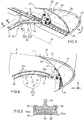
- the wing comprises a device for setting the movable leading edge flap 16 in motion, this device 50 making it possible to cause the latter to pivot relative to the body 8, along an axis of rotation 18, between the fully deployed position and the retracted position.
- the device for setting in motion firstly comprises at least one drive rail 20 arranged in a transverse plane of the shutter. In the preferred case where several rails 20 are provided, these are then spaced from each other in the direction of span X.
- Each drive rail 20 has a movable character, since it is intended to be rotated about the axis 18, as will be detailed below. It has a generally curved or circular arc shape, known to those skilled in the art and centered on the axis of rotation 18.
- each drive rail 20 is connected to the shutter 16 by a shutter fitting 30 projecting rearwardly from the closure covering 28, an additional connecting rod 29 being arranged between this same fitting 30 and a point rear end of the front end of the rail 20.
- One of the features of the invention lies in the means for setting the rail 20 in motion, which are produced by a linear electric motor 22 directly driving the rail.
- the linear electric motor 22 therefore forms an integral part of the movement device 50, comprising a primary assembly 52 equipped with at least two fixed carriages 52a comprising coils supplied with electric current.
- the carriages here two in number, are integral with the fixed central body of the wing, for example attached to a front spar of this central box-shaped body, referenced 32 on the figure 2 .
- the motor 22 comprises a mobile secondary assembly 54 comprising a magnetic track arranged on the drive rail 20.
- the permanent magnets 54a of this magnetic track are thus spaced from each other along the rail 20 on which they are fixed. . Consequently, as opposed to the conventional embodiments of linear motors, it is the secondary assembly 54 comprising the magnetic path which is mobile, while the primary assembly 52 comprising the carriages remains fixed on the central body of the wing.
- the permanent magnets 54a are arranged opposite the part 52 'of the fixed carriages which comprises the coils 55.
- each carriage 52a serves as guidance during the rotation of the rails 20 with which these carriages cooperate.
- each carriage 52a may have flanges 56 shaped to receive and guide the lateral ends of the sole of the rail.
- the maintenance of the device in the various deployed positions and in the retracted position is for example ensured either by the device 50 itself, or by additional devices with mechanical, electromechanical, electronic, magnetic, electromagnetic control, etc.
Landscapes
- Engineering & Computer Science (AREA)
- Aviation & Aerospace Engineering (AREA)
- Power Engineering (AREA)
- Physics & Mathematics (AREA)
- Chemical & Material Sciences (AREA)
- Combustion & Propulsion (AREA)
- Electromagnetism (AREA)
- Automation & Control Theory (AREA)
- Linear Motors (AREA)
Claims (2)
- Flugzeugflügel (4), umfassend einen feststehenden mittleren Flügelkörper (8) sowie mindestens eine bewegliche Vorflügelklappe (16), die dazu bestimmt ist, bezüglich des feststehenden mittleren Körpers zwischen einer Einsatzposition und einer zurückgezogenen Position bewegt zu werden, wobei der Flügel eine Vorrichtung (50) umfasst, um die bewegliche Vorflügelklappe in Bewegung zu versetzen, wobei die Vorrichtung (50) mit mindestens einer beweglichen Mitnehmerschiene (20) ausgerüstet ist, die ein mit der beweglichen Klappe verbundenes vorderes Ende aufweist, dadurch gekennzeichnet, dass die Inbewegungsversetzungsvorrichtung (50) einen linearen Elektromotor (22) umfasst, der Folgendes aufweist:- eine Primärbaugruppe (52), die mit mindestens zwei feststehenden Schlitten (52a) ausgerüstet ist, die entlang der beweglichen Mitnehmerschiene (20) voneinander beabstandet sind, wobei jeder feststehende Schlitten (52a) Spulen (55) umfasst, wobei die Primärbaugruppe fest mit dem feststehenden mittleren Körper (8) des Flügels verbunden ist, und- eine bewegliche Sekundärbaugruppe (54), die eine an der Mitnehmerschiene (20) angeordnete Magnetspur aufweist,
und dass die Mitnehmerschiene (20) mittels jedes feststehenden Schlittens (52a) geführt wird. - Flugzeug (1), umfasst mindestens einen Flügel (4) nach Anspruch 1.
Applications Claiming Priority (2)
| Application Number | Priority Date | Filing Date | Title |
|---|---|---|---|
| BE2016/5822A BE1024234B1 (fr) | 2016-11-04 | 2016-11-04 | Aile d’aeronef comprenant un volet mobile de bord d’attaque entraine par un moteur electrique lineaire |
| PCT/EP2017/078002 WO2018083144A1 (fr) | 2016-11-04 | 2017-11-02 | Aile d'aeronef comprenant un volet mobile de bord d'attaque entraine par un moteur electrique lineaire |
Publications (2)
| Publication Number | Publication Date |
|---|---|
| EP3535183A1 EP3535183A1 (de) | 2019-09-11 |
| EP3535183B1 true EP3535183B1 (de) | 2021-03-17 |
Family
ID=57326130
Family Applications (1)
| Application Number | Title | Priority Date | Filing Date |
|---|---|---|---|
| EP17803809.7A Not-in-force EP3535183B1 (de) | 2016-11-04 | 2017-11-02 | Flugzeugflügel mit einer beweglichen, von einem linearelektromotor angetriebenen vorderkantenklappe |
Country Status (5)
| Country | Link |
|---|---|
| US (1) | US11440641B2 (de) |
| EP (1) | EP3535183B1 (de) |
| BE (1) | BE1024234B1 (de) |
| CA (1) | CA3041978A1 (de) |
| WO (1) | WO2018083144A1 (de) |
Families Citing this family (3)
| Publication number | Priority date | Publication date | Assignee | Title |
|---|---|---|---|---|
| CN113501126B (zh) * | 2021-05-26 | 2024-05-10 | 中国商用飞机有限责任公司 | 一种用于飞行器的襟翼支持装置 |
| EP4112450A1 (de) * | 2021-06-30 | 2023-01-04 | Airbus Operations GmbH | Flügel für ein flugzeug |
| EP4137401B1 (de) * | 2021-08-18 | 2025-12-17 | Airbus Operations GmbH | Verbindungsanordnung einer hochauftriebsvorrichtung und damit ausgerüsteter flügel und flugzeug |
Family Cites Families (10)
| Publication number | Priority date | Publication date | Assignee | Title |
|---|---|---|---|---|
| US4399970A (en) * | 1980-11-13 | 1983-08-23 | The Boeing Company | Wing leading edge slat |
| US5686907A (en) | 1995-05-15 | 1997-11-11 | The Boeing Company | Skew and loss detection system for individual high lift devices |
| EP1328438A4 (de) * | 2000-09-22 | 2009-04-01 | Diversified Technologies Inc | Läuferschaufel mit variabler kante |
| KR101002105B1 (ko) * | 2008-03-14 | 2010-12-17 | 조윤현 | 체인형 구조로 된 분할 치코어형 선형전동기 |
| BE1018114A5 (fr) * | 2008-05-06 | 2010-05-04 | Sonaca Sociutu Anonyme | Aile d'aeronef comprenant un volet mobile de bord d'attaque equipe d'un rail suiveur contraint en deplacement selon une trajectoire en arc de cercle |
| ES2578714T3 (es) * | 2011-03-28 | 2016-07-29 | Deutsches Zentrum für Luft- und Raumfahrt e.V. | Aleta de borde de ataque adaptativa |
| DE102014101276A1 (de) * | 2014-02-03 | 2015-08-06 | Deutsches Zentrum für Luft- und Raumfahrt e.V. | Linearmotor und Linearsteller |
| BE1022531B1 (fr) | 2014-10-20 | 2016-05-24 | Sonaca S.A. | Systeme ameliore pour la gestion duale de l'antigivrage et de l'aspiration de la couche limite sur une surface portante d'un aeronef |
| US20160226349A1 (en) * | 2014-12-01 | 2016-08-04 | Hamilton Sundstrand Corporation | Electromechanical linear actuator |
| BE1024090B1 (fr) | 2015-07-07 | 2017-11-13 | Sonaca S.A. | Systeme pour la gestion duale de l'antigivrage et de l'aspiration de la couche limite sur une surface portante d'un aeronef, comprenant une fonction de collecte de l'air d'antigivrage |
-
2016
- 2016-11-04 BE BE2016/5822A patent/BE1024234B1/fr not_active IP Right Cessation
-
2017
- 2017-11-02 CA CA3041978A patent/CA3041978A1/fr active Pending
- 2017-11-02 US US16/345,767 patent/US11440641B2/en active Active
- 2017-11-02 EP EP17803809.7A patent/EP3535183B1/de not_active Not-in-force
- 2017-11-02 WO PCT/EP2017/078002 patent/WO2018083144A1/fr not_active Ceased
Non-Patent Citations (1)
| Title |
|---|
| None * |
Also Published As
| Publication number | Publication date |
|---|---|
| BR112019008645A2 (pt) | 2019-07-09 |
| CA3041978A1 (fr) | 2018-05-11 |
| EP3535183A1 (de) | 2019-09-11 |
| BE1024234B1 (fr) | 2017-12-21 |
| US11440641B2 (en) | 2022-09-13 |
| WO2018083144A1 (fr) | 2018-05-11 |
| US20200055589A1 (en) | 2020-02-20 |
Similar Documents
| Publication | Publication Date | Title |
|---|---|---|
| EP2116467B1 (de) | Luftfahrzeugflügel, der eine verstellbare Klappe an der Vorderkante umfasst, die mit einer zur Bewegung auf einem Kreisbogen zwingenden Führungsschiene ausgestattet ist | |
| EP2406133B1 (de) | Flugzeug mit frack-schwanzanordnung und heckmotor | |
| EP3728023B1 (de) | Flugzeugflügel mit einer beweglichen vorderkantenklappe, die von einer an der vorderseite eines flügelkastens angeordneten vorrichtung geführt wird | |
| CA2169874C (fr) | Inverseur de poussee a volets aval pour turboreacteur | |
| EP1588938B1 (de) | Aerodynamische Verkleidung für ein Flugzeugfahrwerk | |
| FR2958624A1 (fr) | Mat d'accrochage pour turbomoteur d'aeronef, comprenant un volet arriere mobile en incidence | |
| FR2992629A1 (fr) | Dispositif de liaison mecanique d'une gouverne a un element structural fixe d'aeronef et element de voilure d'aeronef equipe de ce dispositif | |
| FR2933953A1 (fr) | Avion a empennage vertical a surface variable | |
| FR2868754A1 (fr) | Avion supersonique a ailes variables deployees vers l'avant, presentant a la fois une caracteristique de faible bang et une caracteristique de faible trainee | |
| EP4164943B1 (de) | Propelleranordnung mit faltbaren blättern und verfahren zum falten der blätter | |
| BE1024234B1 (fr) | Aile d’aeronef comprenant un volet mobile de bord d’attaque entraine par un moteur electrique lineaire | |
| EP3495266A1 (de) | Flugzeug mit evolutiver konfiguration im flug | |
| WO2017168088A1 (fr) | Dispositif propulsif a portance active | |
| EP2595879A1 (de) | Verfahren und vorrichtung zur seitlichen stabilisierung eines flugzeugs | |
| EP3488094B1 (de) | System zur betätigung einer platte einer turbostrahltriebwerksgondel | |
| FR2902756A1 (fr) | Systeme de deportance au sol d'un aeronef et aeroplane comportant un tel systeme | |
| FR3061146A1 (fr) | Aeronef a moteur arriere porte par au moins un bras dans une position decalee en arriere et a distance d'une extremite arriere de la cellule de l'aeronef | |
| FR3022217A1 (fr) | Aeronef convertible a aile basculante | |
| EP4361429B1 (de) | Turbofantriebwerk mit beweglichen ablenkplatten und einem system zur betätigung der deflektoren | |
| BE1024276B1 (fr) | Aile d’aeronef comprenant un volet mobile de bord de fuite entraine par un moteur electrique lineaire | |
| BE1030173B1 (fr) | Volet mobile de bord d'attaque a chemins multiples de passage d'efforts | |
| BE1032402B1 (fr) | Système de déplacement d'un volet mobile de bord d'attaque d'une aile d'aéronef, comprenant un carénage aérodynamique agencé autour d'un rail de ce système | |
| EP3693593A1 (de) | Turbotriebwerk, das einen antriebsmechanismus eines schubumkehrsystems umfasst | |
| FR3078995A1 (fr) | Groupe propulseur d'aeronef dont la nacelle est liee par un pivot a l'arbre d'entrainement de sa soufflante | |
| FR3094953A1 (fr) | Voilure tournante dans le domaine des aéronefs |
Legal Events
| Date | Code | Title | Description |
|---|---|---|---|
| STAA | Information on the status of an ep patent application or granted ep patent |
Free format text: STATUS: UNKNOWN |
|
| STAA | Information on the status of an ep patent application or granted ep patent |
Free format text: STATUS: THE INTERNATIONAL PUBLICATION HAS BEEN MADE |
|
| PUAI | Public reference made under article 153(3) epc to a published international application that has entered the european phase |
Free format text: ORIGINAL CODE: 0009012 |
|
| STAA | Information on the status of an ep patent application or granted ep patent |
Free format text: STATUS: REQUEST FOR EXAMINATION WAS MADE |
|
| 17P | Request for examination filed |
Effective date: 20190509 |
|
| AK | Designated contracting states |
Kind code of ref document: A1 Designated state(s): AL AT BE BG CH CY CZ DE DK EE ES FI FR GB GR HR HU IE IS IT LI LT LU LV MC MK MT NL NO PL PT RO RS SE SI SK SM TR |
|
| AX | Request for extension of the european patent |
Extension state: BA ME |
|
| RIN1 | Information on inventor provided before grant (corrected) |
Inventor name: SCIARRABONE, STEVE Inventor name: DEBAISIEUX, STEPHANE |
|
| DAV | Request for validation of the european patent (deleted) | ||
| DAX | Request for extension of the european patent (deleted) | ||
| STAA | Information on the status of an ep patent application or granted ep patent |
Free format text: STATUS: EXAMINATION IS IN PROGRESS |
|
| 17Q | First examination report despatched |
Effective date: 20200603 |
|
| REG | Reference to a national code |
Ref country code: DE Ref legal event code: R079 Ref document number: 602017034881 Country of ref document: DE Free format text: PREVIOUS MAIN CLASS: B64C0009220000 Ipc: H02K0007140000 |
|
| GRAP | Despatch of communication of intention to grant a patent |
Free format text: ORIGINAL CODE: EPIDOSNIGR1 |
|
| STAA | Information on the status of an ep patent application or granted ep patent |
Free format text: STATUS: GRANT OF PATENT IS INTENDED |
|
| RIC1 | Information provided on ipc code assigned before grant |
Ipc: B64C 9/22 20060101ALI20200918BHEP Ipc: H02K 7/14 20060101AFI20200918BHEP |
|
| INTG | Intention to grant announced |
Effective date: 20201013 |
|
| GRAS | Grant fee paid |
Free format text: ORIGINAL CODE: EPIDOSNIGR3 |
|
| GRAA | (expected) grant |
Free format text: ORIGINAL CODE: 0009210 |
|
| STAA | Information on the status of an ep patent application or granted ep patent |
Free format text: STATUS: THE PATENT HAS BEEN GRANTED |
|
| AK | Designated contracting states |
Kind code of ref document: B1 Designated state(s): AL AT BE BG CH CY CZ DE DK EE ES FI FR GB GR HR HU IE IS IT LI LT LU LV MC MK MT NL NO PL PT RO RS SE SI SK SM TR |
|
| REG | Reference to a national code |
Ref country code: GB Ref legal event code: FG4D Free format text: NOT ENGLISH |
|
| REG | Reference to a national code |
Ref country code: CH Ref legal event code: EP |
|
| REG | Reference to a national code |
Ref country code: DE Ref legal event code: R096 Ref document number: 602017034881 Country of ref document: DE |
|
| REG | Reference to a national code |
Ref country code: IE Ref legal event code: FG4D Free format text: LANGUAGE OF EP DOCUMENT: FRENCH |
|
| REG | Reference to a national code |
Ref country code: AT Ref legal event code: REF Ref document number: 1373161 Country of ref document: AT Kind code of ref document: T Effective date: 20210415 |
|
| REG | Reference to a national code |
Ref country code: LT Ref legal event code: MG9D |
|
| PG25 | Lapsed in a contracting state [announced via postgrant information from national office to epo] |
Ref country code: FI Free format text: LAPSE BECAUSE OF FAILURE TO SUBMIT A TRANSLATION OF THE DESCRIPTION OR TO PAY THE FEE WITHIN THE PRESCRIBED TIME-LIMIT Effective date: 20210317 Ref country code: GR Free format text: LAPSE BECAUSE OF FAILURE TO SUBMIT A TRANSLATION OF THE DESCRIPTION OR TO PAY THE FEE WITHIN THE PRESCRIBED TIME-LIMIT Effective date: 20210618 Ref country code: HR Free format text: LAPSE BECAUSE OF FAILURE TO SUBMIT A TRANSLATION OF THE DESCRIPTION OR TO PAY THE FEE WITHIN THE PRESCRIBED TIME-LIMIT Effective date: 20210317 Ref country code: NO Free format text: LAPSE BECAUSE OF FAILURE TO SUBMIT A TRANSLATION OF THE DESCRIPTION OR TO PAY THE FEE WITHIN THE PRESCRIBED TIME-LIMIT Effective date: 20210617 Ref country code: BG Free format text: LAPSE BECAUSE OF FAILURE TO SUBMIT A TRANSLATION OF THE DESCRIPTION OR TO PAY THE FEE WITHIN THE PRESCRIBED TIME-LIMIT Effective date: 20210617 |
|
| REG | Reference to a national code |
Ref country code: AT Ref legal event code: MK05 Ref document number: 1373161 Country of ref document: AT Kind code of ref document: T Effective date: 20210317 |
|
| REG | Reference to a national code |
Ref country code: NL Ref legal event code: MP Effective date: 20210317 |
|
| PG25 | Lapsed in a contracting state [announced via postgrant information from national office to epo] |
Ref country code: SE Free format text: LAPSE BECAUSE OF FAILURE TO SUBMIT A TRANSLATION OF THE DESCRIPTION OR TO PAY THE FEE WITHIN THE PRESCRIBED TIME-LIMIT Effective date: 20210317 Ref country code: LV Free format text: LAPSE BECAUSE OF FAILURE TO SUBMIT A TRANSLATION OF THE DESCRIPTION OR TO PAY THE FEE WITHIN THE PRESCRIBED TIME-LIMIT Effective date: 20210317 Ref country code: RS Free format text: LAPSE BECAUSE OF FAILURE TO SUBMIT A TRANSLATION OF THE DESCRIPTION OR TO PAY THE FEE WITHIN THE PRESCRIBED TIME-LIMIT Effective date: 20210317 |
|
| PG25 | Lapsed in a contracting state [announced via postgrant information from national office to epo] |
Ref country code: NL Free format text: LAPSE BECAUSE OF FAILURE TO SUBMIT A TRANSLATION OF THE DESCRIPTION OR TO PAY THE FEE WITHIN THE PRESCRIBED TIME-LIMIT Effective date: 20210317 |
|
| PG25 | Lapsed in a contracting state [announced via postgrant information from national office to epo] |
Ref country code: LT Free format text: LAPSE BECAUSE OF FAILURE TO SUBMIT A TRANSLATION OF THE DESCRIPTION OR TO PAY THE FEE WITHIN THE PRESCRIBED TIME-LIMIT Effective date: 20210317 Ref country code: EE Free format text: LAPSE BECAUSE OF FAILURE TO SUBMIT A TRANSLATION OF THE DESCRIPTION OR TO PAY THE FEE WITHIN THE PRESCRIBED TIME-LIMIT Effective date: 20210317 Ref country code: CZ Free format text: LAPSE BECAUSE OF FAILURE TO SUBMIT A TRANSLATION OF THE DESCRIPTION OR TO PAY THE FEE WITHIN THE PRESCRIBED TIME-LIMIT Effective date: 20210317 Ref country code: SM Free format text: LAPSE BECAUSE OF FAILURE TO SUBMIT A TRANSLATION OF THE DESCRIPTION OR TO PAY THE FEE WITHIN THE PRESCRIBED TIME-LIMIT Effective date: 20210317 Ref country code: AT Free format text: LAPSE BECAUSE OF FAILURE TO SUBMIT A TRANSLATION OF THE DESCRIPTION OR TO PAY THE FEE WITHIN THE PRESCRIBED TIME-LIMIT Effective date: 20210317 |
|
| PG25 | Lapsed in a contracting state [announced via postgrant information from national office to epo] |
Ref country code: SK Free format text: LAPSE BECAUSE OF FAILURE TO SUBMIT A TRANSLATION OF THE DESCRIPTION OR TO PAY THE FEE WITHIN THE PRESCRIBED TIME-LIMIT Effective date: 20210317 Ref country code: RO Free format text: LAPSE BECAUSE OF FAILURE TO SUBMIT A TRANSLATION OF THE DESCRIPTION OR TO PAY THE FEE WITHIN THE PRESCRIBED TIME-LIMIT Effective date: 20210317 Ref country code: PL Free format text: LAPSE BECAUSE OF FAILURE TO SUBMIT A TRANSLATION OF THE DESCRIPTION OR TO PAY THE FEE WITHIN THE PRESCRIBED TIME-LIMIT Effective date: 20210317 Ref country code: PT Free format text: LAPSE BECAUSE OF FAILURE TO SUBMIT A TRANSLATION OF THE DESCRIPTION OR TO PAY THE FEE WITHIN THE PRESCRIBED TIME-LIMIT Effective date: 20210719 Ref country code: IS Free format text: LAPSE BECAUSE OF FAILURE TO SUBMIT A TRANSLATION OF THE DESCRIPTION OR TO PAY THE FEE WITHIN THE PRESCRIBED TIME-LIMIT Effective date: 20210717 |
|
| REG | Reference to a national code |
Ref country code: DE Ref legal event code: R097 Ref document number: 602017034881 Country of ref document: DE |
|
| PLBE | No opposition filed within time limit |
Free format text: ORIGINAL CODE: 0009261 |
|
| STAA | Information on the status of an ep patent application or granted ep patent |
Free format text: STATUS: NO OPPOSITION FILED WITHIN TIME LIMIT |
|
| PG25 | Lapsed in a contracting state [announced via postgrant information from national office to epo] |
Ref country code: ES Free format text: LAPSE BECAUSE OF FAILURE TO SUBMIT A TRANSLATION OF THE DESCRIPTION OR TO PAY THE FEE WITHIN THE PRESCRIBED TIME-LIMIT Effective date: 20210317 Ref country code: AL Free format text: LAPSE BECAUSE OF FAILURE TO SUBMIT A TRANSLATION OF THE DESCRIPTION OR TO PAY THE FEE WITHIN THE PRESCRIBED TIME-LIMIT Effective date: 20210317 Ref country code: DK Free format text: LAPSE BECAUSE OF FAILURE TO SUBMIT A TRANSLATION OF THE DESCRIPTION OR TO PAY THE FEE WITHIN THE PRESCRIBED TIME-LIMIT Effective date: 20210317 |
|
| 26N | No opposition filed |
Effective date: 20211220 |
|
| PG25 | Lapsed in a contracting state [announced via postgrant information from national office to epo] |
Ref country code: SI Free format text: LAPSE BECAUSE OF FAILURE TO SUBMIT A TRANSLATION OF THE DESCRIPTION OR TO PAY THE FEE WITHIN THE PRESCRIBED TIME-LIMIT Effective date: 20210317 |
|
| PG25 | Lapsed in a contracting state [announced via postgrant information from national office to epo] |
Ref country code: IT Free format text: LAPSE BECAUSE OF FAILURE TO SUBMIT A TRANSLATION OF THE DESCRIPTION OR TO PAY THE FEE WITHIN THE PRESCRIBED TIME-LIMIT Effective date: 20210317 |
|
| PG25 | Lapsed in a contracting state [announced via postgrant information from national office to epo] |
Ref country code: IS Free format text: LAPSE BECAUSE OF FAILURE TO SUBMIT A TRANSLATION OF THE DESCRIPTION OR TO PAY THE FEE WITHIN THE PRESCRIBED TIME-LIMIT Effective date: 20210717 |
|
| PG25 | Lapsed in a contracting state [announced via postgrant information from national office to epo] |
Ref country code: MC Free format text: LAPSE BECAUSE OF FAILURE TO SUBMIT A TRANSLATION OF THE DESCRIPTION OR TO PAY THE FEE WITHIN THE PRESCRIBED TIME-LIMIT Effective date: 20210317 |
|
| REG | Reference to a national code |
Ref country code: CH Ref legal event code: PL |
|
| PG25 | Lapsed in a contracting state [announced via postgrant information from national office to epo] |
Ref country code: LU Free format text: LAPSE BECAUSE OF NON-PAYMENT OF DUE FEES Effective date: 20211102 |
|
| PG25 | Lapsed in a contracting state [announced via postgrant information from national office to epo] |
Ref country code: LI Free format text: LAPSE BECAUSE OF NON-PAYMENT OF DUE FEES Effective date: 20211130 Ref country code: CH Free format text: LAPSE BECAUSE OF NON-PAYMENT OF DUE FEES Effective date: 20211130 |
|
| PG25 | Lapsed in a contracting state [announced via postgrant information from national office to epo] |
Ref country code: IE Free format text: LAPSE BECAUSE OF NON-PAYMENT OF DUE FEES Effective date: 20211102 |
|
| P01 | Opt-out of the competence of the unified patent court (upc) registered |
Effective date: 20230511 |
|
| PG25 | Lapsed in a contracting state [announced via postgrant information from national office to epo] |
Ref country code: CY Free format text: LAPSE BECAUSE OF FAILURE TO SUBMIT A TRANSLATION OF THE DESCRIPTION OR TO PAY THE FEE WITHIN THE PRESCRIBED TIME-LIMIT Effective date: 20210317 |
|
| PG25 | Lapsed in a contracting state [announced via postgrant information from national office to epo] |
Ref country code: HU Free format text: LAPSE BECAUSE OF FAILURE TO SUBMIT A TRANSLATION OF THE DESCRIPTION OR TO PAY THE FEE WITHIN THE PRESCRIBED TIME-LIMIT; INVALID AB INITIO Effective date: 20171102 |
|
| PGFP | Annual fee paid to national office [announced via postgrant information from national office to epo] |
Ref country code: GB Payment date: 20231128 Year of fee payment: 7 |
|
| PGFP | Annual fee paid to national office [announced via postgrant information from national office to epo] |
Ref country code: FR Payment date: 20231123 Year of fee payment: 7 Ref country code: DE Payment date: 20231122 Year of fee payment: 7 |
|
| PGFP | Annual fee paid to national office [announced via postgrant information from national office to epo] |
Ref country code: BE Payment date: 20231123 Year of fee payment: 7 |
|
| PG25 | Lapsed in a contracting state [announced via postgrant information from national office to epo] |
Ref country code: MK Free format text: LAPSE BECAUSE OF FAILURE TO SUBMIT A TRANSLATION OF THE DESCRIPTION OR TO PAY THE FEE WITHIN THE PRESCRIBED TIME-LIMIT Effective date: 20210317 |
|
| PG25 | Lapsed in a contracting state [announced via postgrant information from national office to epo] |
Ref country code: MT Free format text: LAPSE BECAUSE OF FAILURE TO SUBMIT A TRANSLATION OF THE DESCRIPTION OR TO PAY THE FEE WITHIN THE PRESCRIBED TIME-LIMIT Effective date: 20210317 |
|
| REG | Reference to a national code |
Ref country code: DE Ref legal event code: R119 Ref document number: 602017034881 Country of ref document: DE |
|
| GBPC | Gb: european patent ceased through non-payment of renewal fee |
Effective date: 20241102 |
|
| REG | Reference to a national code |
Ref country code: BE Ref legal event code: MM Effective date: 20241130 |
|
| PG25 | Lapsed in a contracting state [announced via postgrant information from national office to epo] |
Ref country code: DE Free format text: LAPSE BECAUSE OF NON-PAYMENT OF DUE FEES Effective date: 20250603 |
|
| PG25 | Lapsed in a contracting state [announced via postgrant information from national office to epo] |
Ref country code: BE Free format text: LAPSE BECAUSE OF NON-PAYMENT OF DUE FEES Effective date: 20241130 Ref country code: GB Free format text: LAPSE BECAUSE OF NON-PAYMENT OF DUE FEES Effective date: 20241102 |
|
| PG25 | Lapsed in a contracting state [announced via postgrant information from national office to epo] |
Ref country code: FR Free format text: LAPSE BECAUSE OF NON-PAYMENT OF DUE FEES Effective date: 20241130 |
|
| PG25 | Lapsed in a contracting state [announced via postgrant information from national office to epo] |
Ref country code: TR Free format text: LAPSE BECAUSE OF FAILURE TO SUBMIT A TRANSLATION OF THE DESCRIPTION OR TO PAY THE FEE WITHIN THE PRESCRIBED TIME-LIMIT Effective date: 20210317 |