EP3535529B1 - Brennrohr für gasturbine und brennkammer - Google Patents
Brennrohr für gasturbine und brennkammer Download PDFInfo
- Publication number
- EP3535529B1 EP3535529B1 EP17866555.0A EP17866555A EP3535529B1 EP 3535529 B1 EP3535529 B1 EP 3535529B1 EP 17866555 A EP17866555 A EP 17866555A EP 3535529 B1 EP3535529 B1 EP 3535529B1
- Authority
- EP
- European Patent Office
- Prior art keywords
- burner tube
- segment
- face
- downstream
- outer body
- Prior art date
- Legal status (The legal status is an assumption and is not a legal conclusion. Google has not performed a legal analysis and makes no representation as to the accuracy of the status listed.)
- Active
Links
Images


Classifications
-
- F—MECHANICAL ENGINEERING; LIGHTING; HEATING; WEAPONS; BLASTING
- F23—COMBUSTION APPARATUS; COMBUSTION PROCESSES
- F23R—GENERATING COMBUSTION PRODUCTS OF HIGH PRESSURE OR HIGH VELOCITY, e.g. GAS-TURBINE COMBUSTION CHAMBERS
- F23R3/00—Continuous combustion chambers using liquid or gaseous fuel
- F23R3/28—Continuous combustion chambers using liquid or gaseous fuel characterised by the fuel supply
- F23R3/286—Continuous combustion chambers using liquid or gaseous fuel characterised by the fuel supply having fuel-air premixing devices
-
- F—MECHANICAL ENGINEERING; LIGHTING; HEATING; WEAPONS; BLASTING
- F23—COMBUSTION APPARATUS; COMBUSTION PROCESSES
- F23R—GENERATING COMBUSTION PRODUCTS OF HIGH PRESSURE OR HIGH VELOCITY, e.g. GAS-TURBINE COMBUSTION CHAMBERS
- F23R3/00—Continuous combustion chambers using liquid or gaseous fuel
- F23R3/02—Continuous combustion chambers using liquid or gaseous fuel characterised by the air-flow or gas-flow configuration
- F23R3/16—Continuous combustion chambers using liquid or gaseous fuel characterised by the air-flow or gas-flow configuration with devices inside the flame tube or the combustion chamber to influence the air or gas flow
- F23R3/18—Flame stabilising means, e.g. flame holders for after-burners of jet-propulsion plants
- F23R3/20—Flame stabilising means, e.g. flame holders for after-burners of jet-propulsion plants incorporating fuel injection means
-
- F—MECHANICAL ENGINEERING; LIGHTING; HEATING; WEAPONS; BLASTING
- F02—COMBUSTION ENGINES; HOT-GAS OR COMBUSTION-PRODUCT ENGINE PLANTS
- F02C—GAS-TURBINE PLANTS; AIR INTAKES FOR JET-PROPULSION PLANTS; CONTROLLING FUEL SUPPLY IN AIR-BREATHING JET-PROPULSION PLANTS
- F02C3/00—Gas-turbine plants characterised by the use of combustion products as the working fluid
- F02C3/14—Gas-turbine plants characterised by the use of combustion products as the working fluid characterised by the arrangement of the combustion chamber in the plant
-
- F—MECHANICAL ENGINEERING; LIGHTING; HEATING; WEAPONS; BLASTING
- F23—COMBUSTION APPARATUS; COMBUSTION PROCESSES
- F23R—GENERATING COMBUSTION PRODUCTS OF HIGH PRESSURE OR HIGH VELOCITY, e.g. GAS-TURBINE COMBUSTION CHAMBERS
- F23R3/00—Continuous combustion chambers using liquid or gaseous fuel
- F23R3/28—Continuous combustion chambers using liquid or gaseous fuel characterised by the fuel supply
- F23R3/34—Feeding into different combustion zones
- F23R3/343—Pilot flames, i.e. fuel nozzles or injectors using only a very small proportion of the total fuel to insure continuous combustion
-
- F—MECHANICAL ENGINEERING; LIGHTING; HEATING; WEAPONS; BLASTING
- F23—COMBUSTION APPARATUS; COMBUSTION PROCESSES
- F23R—GENERATING COMBUSTION PRODUCTS OF HIGH PRESSURE OR HIGH VELOCITY, e.g. GAS-TURBINE COMBUSTION CHAMBERS
- F23R3/00—Continuous combustion chambers using liquid or gaseous fuel
- F23R3/28—Continuous combustion chambers using liquid or gaseous fuel characterised by the fuel supply
- F23R3/38—Continuous combustion chambers using liquid or gaseous fuel characterised by the fuel supply comprising rotary fuel injection means
-
- F—MECHANICAL ENGINEERING; LIGHTING; HEATING; WEAPONS; BLASTING
- F23—COMBUSTION APPARATUS; COMBUSTION PROCESSES
- F23R—GENERATING COMBUSTION PRODUCTS OF HIGH PRESSURE OR HIGH VELOCITY, e.g. GAS-TURBINE COMBUSTION CHAMBERS
- F23R3/00—Continuous combustion chambers using liquid or gaseous fuel
- F23R3/42—Continuous combustion chambers using liquid or gaseous fuel characterised by the arrangement or form of the flame tubes or combustion chambers
- F23R3/52—Toroidal combustion chambers
-
- F—MECHANICAL ENGINEERING; LIGHTING; HEATING; WEAPONS; BLASTING
- F05—INDEXING SCHEMES RELATING TO ENGINES OR PUMPS IN VARIOUS SUBCLASSES OF CLASSES F01-F04
- F05D—INDEXING SCHEME FOR ASPECTS RELATING TO NON-POSITIVE-DISPLACEMENT MACHINES OR ENGINES, GAS-TURBINES OR JET-PROPULSION PLANTS
- F05D2220/00—Application
- F05D2220/30—Application in turbines
- F05D2220/32—Application in turbines in gas turbines
Definitions
- the present invention is directed to a burner tube for a gas turbine, comprising a premix fuel nozzle.
- US2009111063 discloses a lean premixed, radial inflow, multi-annular staged nozzle for creating three independent combustion zones within a can-annular, dual-fuel gas turbine combustor.
- the nozzle includes a pilot zone fueled by a gas pilot nozzle and center cartridge; a flame holder zone fueled by an inner main gas fuel; a main flame zone fueled by an outer main gas fuel; a main radial swirler for mixing a portion of incoming air to the nozzle with the inner main gas fuel supply and the outer main gas fuel supply; an endcover; and means for controlling the ratio of an inner main gas fuel supplied and an outer main gas fuel supplied.
- a typical gas turbine uses a combustor to produce combustion gases having high pressure and high temperature to produce work.
- a gas turbine typically includes an inlet section, a compressor section, a combustion section, a turbine section and an exhaust section. More specifically, the compressor section supplies a compressed working fluid to the combustion section. The compressed working fluid and a fuel are mixed within the combustion section and burned to generate combustion gases at high pressure and temperature. The combustion gases flow to the turbine section where they expand to produce work. The expanded gases are released in the exhaust section.
- the combustion section includes one or more combustors, each having a combustion casing, an end cover, a cap, fuel nozzles (including a center premix nozzle and several outer premix nozzles surrounding the center premix nozzle), a liner, a flow sleeve and a transition piece.
- the center premix nozzle and the outer premix nozzles take fuel either directly from a connection outside the engine or from a fuel manifold (end cover) and deliver it to the combustor.
- the nozzle requirements include feeding various fluids supplied by the end cover to their desired injection ports, providing flow and fuel distribution to ensure proper functioning of the combustor, holding the flame adj acent to the nozzle without damage to the combustor for a required maintenance interval, and adequate passage seals to provide leak free sealing.
- Previous flame holder concepts have generally been either bluff body or swirl stabilized.
- Bluff body flame holding is where a part of the combustor creates a low speed zone downstream of it where the axial flow speed is low enough to allow flame to remain in it; most such devices create either a trapped or partially trapped vortex in them, as seen, for example, in U.S. Patent No. 7,003,961 (Kendrick et al. ).
- Swirl stabilized flame holding is where a swirler swirls the flow that then naturally blooms and creates a recirculation at its core, as seen, for example, in U.S. Patent No. 6,438,961 (Tuthill et al. ).
- the flame can reside stably in the toroidal vortex created and ignite the inner surface of the flow passing down the burner tube.
- there could also be a vortex outboard of the flow which could also form a flame holder.
- Some systems use a combination of bluff body and swirl stabilized flame holding.
- nozzles It is advantageous in most designs for nozzles to have flames anchored on their downstream tips.
- the tips are often not very large in that they take up flow area. Therefore, the larger the tip size, the larger the burner tube must be to maintain the same flow area. Alternatively, the flow must be increased if the same burner tube size is retained. Increased losses result. It is advantageous and typically more stable to have the biggest recirculation zone possible.
- Recirculation zones bring hot products from the reaction zone upstream along the nozzle centerline to mix with fresh fuel air mixture delivered by the nozzle.
- One way to increase the size of the recirculation zone is to swirl the flow. A blade in the premixing zone spins the flow. This flow passes down an annular pipe until the end of the nozzle, or slightly beyond (if the tip is recessed).
- Swirling the flow has several consequences. Swirling the flow at, for example, 45 degrees against 25 degrees results in higher pressure drop which can use up, for example, 390 KW of energy in a 70 MW gas turbine. That energy is dissipated as heat, some of which is recovered as it expands through the cycle but leads to overall lower power and efficiency. Obviously, not swirling the flow at all would give even bigger gains.
- One way of reducing the pressure loss is to reduce the speed of the flow in the burner tubes as the loss is proportional to velocity squared.
- the presence of larger burner tubes results in even less free cap space available for expansion. It also places the flow streams closer together which increase the shear rates between the flows exiting the premixers.
- the outer nozzles have an advantage inherent in swirl based systems.
- the nozzles by design/concept, have circular symmetry. While flame shape and properties can be varied, it is typically only a radial property, such as fuel profile or swirl that can be varied.
- axial flow is intended to mean a flow field with nominally zero net swirl.
- axial flow may have secondary motion. In this case, there may be flow features with radial and circumferential velocities but the net swirl/radial velocity is essentially zero.
- a burner tube for a gas turbine comprising a premix fuel nozzle which includes a nozzle tip disposed in a burner tube.
- the burner tube has an internal wall, an open internal volume having a length extending between an upstream end and a downstream end of the burner tube, a longitudinal axis and a cross-sectional area perpendicular to the longitudinal axis.
- the nozzle tip includes an outer body having an outer body external face facing the downstream end of the burner tube. The outer body external face has a smaller cross-sectional area than the cross-sectional area of the burner tube.
- the nozzle tip further includes one or more segments radiating radially outwardly toward the internal wall of the burner tube from the outer body, wherein each segment has a proximal end disposed adjacent to the outer body external face and a distal end disposed in a direction toward the burner tube. Each segment has a segment downstream face angled relative to the longitudinal axis of the burner tube towards the downstream end of the burner tube.
- the distal end of at least one of the segments may extend partially or fully to the internal wall of the burner tube.
- the outer body surrounds an inner plenum where the inner plenum is adapted to receive cooling air.
- the outer body has an open end and a closed end, the closed end having an internal face adjacent to the inner plenum.
- the closed end may have a plurality of cooling bore holes extending between the internal face and the outer body external face.
- Each segment comprises an internal conduit having an open proximal end and a closed distal end, the open proximal end in fluid communication with the inner plenum, wherein the air is adapted to pass from the inner plenum into the internal conduit.
- Each segment comprises a plurality of segment bore holes between the internal conduit and the segment downstream face, wherein the bore holes provide fluid communication between the internal conduit and the segment downstream face, to provide for the air to pass from the internal conduit through each segment.
- the segment downstream face of each segment may be planar.
- An angle of the segment downstream face relative to the longitudinal axis B of the burner tube 25 is in the range of 105 to 165 degrees (e.g., approximately 135 degrees).
- the distal end of the at least one segment that fully extends to the internal wall of the burner tube may be closed and have a purge groove.
- Each segment of the segments may be equally circumferentially spaced about the outer body.
- a circumferential cross-sectional area of the proximal end of each segment may be larger than the circumferential cross-sectional area of the distal end of each segment.
- Each segment may have a U-shaped cross-section, wherein the cross-section is parallel to the longitudinal axis of the burner tube.
- Each segment may have an upstream face, wherein the upstream face is smoothly curved toward the segment downstream face.
- Each segment may have an upstream face, wherein the upstream face of each segment is angled relative to the longitudinal axis of the burner tube towards the downstream end of the burner tube.
- a combustor for a gas turbine which includes a reaction zone and one or more premix fuel nozzles.
- the premix fuel nozzle or nozzles are for injecting a fuel and air mixture into the reaction zone.
- At least one of the premix fuel nozzles may include a fuel and air premixer and a nozzle tip disposed in a burner tube.
- the burner tube has an internal wall, an open internal volume having a length extending between an upstream end and a downstream end of the burner tube, a longitudinal axis and a cross-sectional area perpendicular to the longitudinal axis.
- the nozzle tip is as described above.
- the at least one premix fuel nozzle may be a single center premix fuel nozzle wherein the combustor contains at least one outer premix fuel nozzle of a different type.
- the one or more premix fuel nozzles may include both a single center premix fuel nozzle and at least one outer premix fuel nozzle.
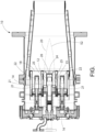
- FIG. 1 a combustor 10 having premix nozzles 12, 22 in accordance with a first exemplary embodiment of the present invention.
- the primary components of the combustor 10 include a combustion casing 14, an end cover 16, a cap 18, a reaction zone 20, the center premix fuel nozzle 12 and a plurality of outer premix fuel nozzles 22.
- the nozzles 12, 22 are for injecting an air and fuel mixture 21 into the reaction zone 20.
- the premix fuel nozzles 12, 22 generally include a fuel and air premixer 23, a nozzle tip 24 and a burner tube 25. It is noted that the present invention for a nozzle tip 24 may be satisfactorily used with some of or all of the center premix fuel nozzle 12 and the outer premix fuel nozzles. For clarity, the invention is generally described here with respect to the center premix nozzle alone, but the nozzle tip 24 of the present invention may be used with any nozzle 12, 22.
- the nozzle tip 24 includes an outer body 26 surrounding an inner plenum 28.
- the burner tube 25 has an internal wall 27, an open internal volume 29, and has a length 31 extending between an upstream end 33 and a downstream end 35 of the burner tube 25 (see FIG. 8 ).
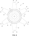
- the burner tube 25 has a longitudinal axis B and a cross-sectional area 39 (shown as cross-hatched area in FIG. 4 ) that is perpendicular to the burner tube 25.
- the outer body 26 of the nozzle tip 24 has an open end 30, a closed end 32 and an outer body external face 36 on the closed end 32 facing the downstream end 35 of the burner tube 25.
- the outer body external face 36 faces the downstream end 35 of the burner tube 25 and has a smaller cross-sectional area 37 than the cross-sectional area 39 of the burner tube 25 (compare the diagonal lined section to the cross-hatched portion of FIG. 4 .
- the outer body external face 36 may be planar.
- the inner plenum 28 is adapted to receive cooling air.
- the closed end 32 of the nozzle tip 24 has an internal face 34 adjacent to the inner plenum 28.
- the closed end 32 has a plurality of bore holes 38 extending between the internal face 34 and the outer body external face 36. These bore holes 38 may be disposed at an angle relative to the longitudinal axis B of the burner tube 25, as is known in the art.
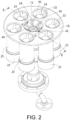
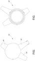
- At least one segment 40 radiates outwardly from the outer body 26 towards the internal wall 27 of the burner tube 25, for example, at evenly spaced circumferential intervals.
- Each segment 40 may be the same length or different lengths and may extend fully to the burner tube internal wall 27 or partially to the burner tube internal wall 27.
- An example of a burner tip 24' having different length segments at irregular angles 40' is shown in FIGS. 10-13 .
- the burner tip 24' is shown without the optional bore holes (discussed below).
- the simplest usage has an equal number of segments 40 to the quantity of outer premix nozzles 22.
- One permutation has the segments 40 align with the outer premix nozzles 22 to carry flame from the center premix nozzle 12 to the outer premix fuel nozzles 22.
- each segment 40 comprises an internal conduit 42 having an open proximal end 44 (see FIG. 8 ) in fluid communication with the inner plenum 28, wherein air is adapted to pass from the inner plenum 28 into the internal conduit 42.
- Each segment 40 also has a closed distal end 46, a segment downstream face 48 (e.g., planar) disposed adjacent to the outer body external face 36 of the outer body 26, and a plurality of segment bore holes 50 between the internal conduit 42 and the segment downstream face 48.
- the bore holes 50 provide fluid communication between the internal conduit 42 and the segment downstream face 48 to provide for air to pass from the internal conduit 42 through each segment 40.
- the segment downstream face 48 of each segment 40 is at an angle relative to the longitudinal axis B of the burner tube 25 of 105 to 165 degrees. E.g., see FIG. 9 , angle C.
- each segment 40 may include a purge groove 54 to ensure that there is always an air and fuel mixture flow passing over the nozzle tip 24. If the segment 40 is approximately the same height as the burner tube 25 and extends to the internal wall 27 of the burner tube ( e.g ., as shown in FIGS. 4 and 8 ), the purge groove 54 ensures that the area of the distal end 46 of the segment 40 is continually flushed even if the two parts are touching or nearly touching. Such a purge groove 54 is not necessary for shorter length segments 40' as shown in FIGS. 10-13 .
- the segments 40 may be of a shape shown in the various figures (see FIGS. 2 and 4- 12). However, it is the intent of the present invention to include segments of substantially any elongate configuration that operates suitably to achieve the results desired, as stated herein.
- the upstream portions of the various segments 40 should have a suitable aerodynamic geometry to ensure there are substantially no separation zones upstream of the trailing edges (i.e., the edges of the segment downstream faces 48 of the segments 40).
- having such clean aerodynamic trailing edges of the various segments is of substantially lesser importance.
- the various segments 40 on a nozzle tip 24 may have identical physical geometries, but, alternatively, one or more segment 40 on a nozzle tip 24 may have an entirely different geometry, so long as the desired results described herein are achieved, including strong flame holding and strong flame propagation.
- the nozzle tip 24 creates two or more recirculation zones of differing radial extent combining to form an irregular toroidal recirculation zone 52 of the fuel and air mixture to provide strong flame holding and flame propagation.
- a normal swirling nozzle has a single toroidal vortex that is a figure of revolution.
- the recirculation zone is composed of two or more zones of differing radial extent and is an irregular toroid, i.e ., not a figure of revolution.
- the present invention creates different size vortices that may be tailored to create differing flame shapes with differing properties.
- the present invention provides segments 40 to, in effect, make a hole in the flow of air and fuel mixture to create a low speed flow zone on the downstream side where axial velocity is lower than the flame speed and is spun up by the flow passing between the burner tube and the distal ends 46 of the segments 40.
- the segments 40 of the nozzle tip 24, if disposed in alignment with the outer premix nozzles 22, provide an apparatus by which the center premix nozzle 12, which is always operating, may share flame and ignite the outer premix nozzles 22 which stage on and off during the gas turbine load process.
- flow moves from the center nozzle tip outboard towards the outer nozzle.
- the problem solved by the present invention is the creation of a nozzle architecture that uses linear flow rather than swirl flow.
- the present invention creates a recirculation zone on the nozzle tip with two or more sizes of toroidal flow feature. This creates strong local flame holding and flame propagation while the simplicity of the flow field allows the explicit design of the shape of the downstream flame sheet and thus its properties (within the physical limitations of the design).
- the goal of the present invention is to create a recirculation zone with differing radial extent downstream of the nozzle tip.
- the tip In a swirling design the tip has circular symmetry and is a shape of rotation due to the swirling nature of the flow. In a design with linear flow, as in the present invention, that is not necessary. Any part of the tip can be unique.
- the advantage of present invention is that it brings some of the features of a larger nozzle to a smaller nozzle.
- the present invention is:
- the present invention provides the ability to directly design the flame shape/geometric properties.
- features of the nozzles were altered in an effort to cause a change in flame properties, but the exact nature of that change was not well known.
- the complex interaction of a swirling flow even with the relatively simple geometric environment of a combustor, can make true design effectively impossible.
- the effect of the swirl means that the clocking of any characteristic varies with axial distance so the change might be advantageous at one point and disadvantageous at another.
- each segment 40 requires each segment 40 to have a segment downstream face 48 angled relative to the longitudinal axis B of the burner tube towards the downstream end of the burner tube 25. Due to the fact that the downstream face 48 is angled, when the gas turbine is in operation, an axial flow field of an air and fuel mixture flows through the burner tube and around the nozzle tip, and two or more recirculation zones of differing radial extent are generated on the nozzle tip by the segments to provide strong flame holding and flame propagation.
- FIGS. 14a and 15a show a partial simplified simulated flow field through a burner tube 25 and around a nozzle tip 24 of the present invention where a segment 40 has a downstream face 48 angled relative to the longitudinal axis B of the burner tube, to FIGS.
- FIG. 14b and 15b which show a simulated flow field through a burner tube 25b and around a nozzle tip 24b where a segment 40b has a downstream face 48b that is not angled relative to the longitudinal axis B' of the burner tube 25b (i.e., it is perpendicular to the longitudinal axis B' of the burner tube 25b).
- FIG. 14a shows a recirculation zone of a size similar to the segment height, while FIG. 14b does not.
- the key characteristic of the segmented nozzle tip 24 of the present invention is this ability to create two or more vortices of different size downstream of the segment downstream face 48.
- the flow passing between the burner tube 25, the segment downstream faces 48 and the outer body 26 of the nozzle tip 24 shear on the air downstream of the segment downstream faces 48. This shearing motion carries flow downstream. Flow of the air and fuel mixture 21 therefore travels up the nozzle centerline to replace the displaced flow. Very rapidly after flow starts passing down the burner tube 25, vortices build up downstream of the nozzle tip 24. Since the external face of the nozzle tip 36 and segments 40 have differing radial dimensions the vortices associated with these structures are similarly of different sizes. There is a vortex produced downstream of each segment 40 and one for each zone between segments 40. Therefore, the total number of vortex structures is equal to twice the number of segments 40 with a minimum of two for a single segment 40.
- the axis of rotation of these vortices is parallel to the front face of the gutter or radial relative to the centerline of the combustor. Flow features with these characteristics do not cause the recirculation of flow onto the nozzle/combustor centerline as is the case for a nozzle tip 24 having segments with downstream faces 48 angled relative to the longitudinal axis B of the burner tube 25 towards the downstream end of the burner tube 25.
Landscapes
- Engineering & Computer Science (AREA)
- Chemical & Material Sciences (AREA)
- Combustion & Propulsion (AREA)
- Mechanical Engineering (AREA)
- General Engineering & Computer Science (AREA)
- Gas Burners (AREA)
Claims (12)
- Ein Brennerrohr (25) für eine Gasturbine, mit einer Vormischbrennstoffdüse (12, 22), die eine Düsenspitze (24) aufweist, die in dem Brennerrohr (25) angeordnet ist, wobei das Brennerrohr (25) eine Innenwand (27) aufweist, ein offenes Innenvolumen (29) mit einer Länge (31), die sich zwischen einem stromaufwärtigen Ende (33) und einem stromabwärtigen Ende (35) des Brennerrohrs (25) erstreckt, einer Längsachse (B) und einer Querschnittsfläche (39) senkrecht zur Längsachse (B), wobei die Düsenspitze (24) umfasst:(a) einen Außenkörper (26) mit einer Außenkörper-Außenfläche (36), die dem stromabwärtigen Ende (35) des Brennerrohrs (25) zugewandt ist, wobei die Außenkörper-Außenfläche (36) eine kleinere Querschnittsfläche (37) als die Querschnittsfläche (39) des Brennerrohrs (25) aufweist; und(b) ein oder mehrere Segmente (40), die sich von dem Außenkörper (26) radial nach außen in Richtung der Innenwand (27) des Brennerrohrs (25) erstrecken, wobei jedes Segment (40) ein proximales Ende, das neben der Außenfläche (36) des Außenkörpers angeordnet ist, und ein distales Ende (46) aufweist, das in Richtung des Brennerrohrs (25) angeordnet ist, wobei jedes Segment (40) eine stromabwärtige Segmentfläche (48) aufweist, die relativ zur Längsachse (B) des Brennerrohrs (25) zum stromabwärtigen Ende (35) des Brennerrohrs (25) hin in einem Winkel von 105 bis 165 Grad abgewinkelt ist;wobei im Betrieb der Gasturbine ein axiales Strömungsfeld eines Luft-BrennstoffGemisches durch das Brennerrohr (25) und um die Düsenspitze (24) herum strömt und an der Düsenspitze (24) durch die Segmente (40) zwei oder mehr Rezirkulationszonen unterschiedlicher radialer Ausdehnung erzeugt werden, die für eine starke Flammenhaltung und Flammenausbreitung sorgen,wobei der äußere Körper (26) eine innere Kammer (28) umgibt, wobei die innere Kammer (28) geeignet ist, Kühlluft aufzunehmen, wobei der äußere Körper (26) ein offenes Ende und ein geschlossenes Ende (32) aufweist, wobei das geschlossene Ende (32) eine Innenfläche (34) aufweist, die an die innere Kammer (28) angrenztdadurch gekennzeichnet, dass jedes Segment (40) umfasst:(a) eine innere Leitung (42) mit einem offenen proximalen Ende (44) und einem geschlossenen distalen Ende, wobei das offene proximale Ende (44) in Fluidverbindung mit dem inneren Plenum (28) steht, wobei die Luft so angepasst ist, dass sie von dem inneren Plenum (28) in die innere Leitung (42) gelangt; und(b) eine Vielzahl von Segmentbohrungen (50) zwischen der inneren Leitung (42) und der stromabwärts gelegenen Segmentfläche (48), wobei die Bohrungen eine Fluidverbindung zwischen der inneren Leitung (42) und der stromabwärts gelegenen Segmentfläche (48) herstellen, damit die Luft von der inneren Leitung (42) durch jedes Segment (40) strömen kann.
- Das Brennerrohr (25) gemäß Anspruch 1, wobei das distale Ende (46) mindestens einem der Segmente (40) teilweise bis zur Innenwand (27) des Brennerrohrs (25) reicht.
- Das Brennerrohr (25) gemäß Anspruch 1, wobei sich das distale Ende von mindestens einem der Segmente (40) vollständig bis zur Innenwand (27) des Brennerrohrs (25) erstreckt.
- Das Brennerrohr (25) gemäß Anspruch 1, wobei das geschlossene Ende (32) mehrere Kühlbohrungen aufweist, die sich zwischen der Innenfläche (34) und der Außenfläche (36) des Außenkörpers erstrecken.
- Das Brennerrohr (25) gemäß einem der Ansprüche 1 bis 4, wobei die stromabwärts gelegene Segmentfläche (48) jedes der Segmente (40) planar ist.
- Das Brennerrohr (25) gemäß Anspruch 3, wobei das distale Ende des mindestens einen Segments (40), das sich vollständig bis zur Innenwand (27) des Brennerrohrs (25) erstreckt, geschlossen ist und eine Spülnut (54) aufweist.
- Das Brennerrohr (25) gemäß einem der Ansprüche 1 bis 6, wobei jedes Segment (40) der Segmente (40) in gleichem Umfangsabstand um den Außenkörper (26) angeordnet ist.
- Das Brennerrohr (25) gemäß einem der Ansprüche 1 bis 7, wobei eine Umfangsquerschnittsfläche des proximalen Endes jedes Segments (40) größer ist als die Umfangsquerschnittsfläche des distalen Endes (46) jedes Segments (40).
- Das Brennerrohr (25) gemäß Anspruch 5, wobei jedes Segment (40) einen U-förmigen Querschnitt aufweist, wobei der Querschnitt parallel zur Längsachse (B) des Brennerrohrs (25) verläuft.
- Das Brennerrohr (25) gemäß einem der Ansprüche 1 bis 9, wobei jedes Segment (40) eine stromaufwärts gelegene Fläche aufweist, wobei die stromaufwärts gelegene Fläche in Richtung der stromabwärts gelegenen Fläche (48) des Segments sanft gekrümmt ist.
- Das Brennerrohr (25) gemäß einem der Ansprüche 1 bis 9, wobei jedes Segment (40) eine stromaufwärtige Fläche aufweist, wobei die stromaufwärtige Fläche jedes Segments (40) relativ zur Längsachse (B) des Brennerrohrs (25) in Richtung des stromabwärtigen Endes (35) des Brennerrohrs (25) abgewinkelt ist.
- Eine Brennkammer (10) für eine Gasturbine, die eine Reaktionszone und eine oder mehrere Vormischbrennstoffdüsen (12, 22) des Brennerrohrs (25) nach einem der Ansprüche 1 bis 11 umfasst, wobei die Vormischbrennstoffdüsen (12, 22) zum Einspritzen eines Brennstoff- und Luftgemischs in die Reaktionszone dienen und mindestens eine der Vormischbrennstoffdüsen (12, 22) Folgendes umfasst: einen Brennstoff- und Luftvormischer (23).
Applications Claiming Priority (2)
| Application Number | Priority Date | Filing Date | Title |
|---|---|---|---|
| CN201610935731.4A CN108019774B (zh) | 2016-11-01 | 2016-11-01 | 用于燃气轮机的预混合燃料喷嘴和燃烧室 |
| PCT/CN2017/108539 WO2018082539A1 (en) | 2016-11-01 | 2017-10-31 | Premix fuel nozzle for a gas turbine and combustor |
Publications (3)
| Publication Number | Publication Date |
|---|---|
| EP3535529A1 EP3535529A1 (de) | 2019-09-11 |
| EP3535529A4 EP3535529A4 (de) | 2020-05-20 |
| EP3535529B1 true EP3535529B1 (de) | 2023-05-10 |
Family
ID=62070548
Family Applications (1)
| Application Number | Title | Priority Date | Filing Date |
|---|---|---|---|
| EP17866555.0A Active EP3535529B1 (de) | 2016-11-01 | 2017-10-31 | Brennrohr für gasturbine und brennkammer |
Country Status (5)
| Country | Link |
|---|---|
| US (1) | US11428414B2 (de) |
| EP (1) | EP3535529B1 (de) |
| JP (1) | JP6873258B2 (de) |
| CN (1) | CN108019774B (de) |
| WO (1) | WO2018082539A1 (de) |
Families Citing this family (5)
| Publication number | Priority date | Publication date | Assignee | Title |
|---|---|---|---|---|
| US11156360B2 (en) * | 2019-02-18 | 2021-10-26 | General Electric Company | Fuel nozzle assembly |
| JP7386024B2 (ja) * | 2019-09-13 | 2023-11-24 | 三菱重工業株式会社 | 冷却流路構造、バーナー及び熱交換器 |
| FI130837B1 (fi) * | 2022-04-12 | 2024-04-16 | Oilon Tech Oy | Poltin sekä kattila-poltin-yhdistelmä |
| CN114877371B (zh) * | 2022-05-06 | 2023-03-31 | 南京航空航天大学 | 一种具有双重稳定火焰机制的先进燃烧室及其燃烧方法 |
| CN118149360A (zh) * | 2024-04-02 | 2024-06-07 | 中国联合重型燃气轮机技术有限公司 | 外围周向分级的燃烧室喷嘴、燃气轮机和分级控制方法 |
Family Cites Families (23)
| Publication number | Priority date | Publication date | Assignee | Title |
|---|---|---|---|---|
| US2780916A (en) | 1952-08-22 | 1957-02-12 | Continental Aviat & Engineerin | Pilot burner for jet engines |
| US5267851A (en) * | 1992-03-16 | 1993-12-07 | General Electric Company | Swirl gutters for isolating flow fields for combustion enhancement at non-baseload operating conditions |
| US5487274A (en) * | 1993-05-03 | 1996-01-30 | General Electric Company | Screech suppressor for advanced low emissions gas turbine combustor |
| KR100550689B1 (ko) | 1998-02-10 | 2006-02-08 | 제너럴 일렉트릭 캄파니 | 가스 터빈의 연소 시스템용 버너 및 연료와 공기의 예비혼합 방법 |
| JP2002031343A (ja) * | 2000-07-13 | 2002-01-31 | Mitsubishi Heavy Ind Ltd | 燃料噴出部材、バーナ、燃焼器の予混合ノズル、燃焼器、ガスタービン及びジェットエンジン |
| JP3872960B2 (ja) * | 2001-02-28 | 2007-01-24 | 株式会社日立製作所 | ガスタ−ビン燃焼器 |
| JP4508474B2 (ja) * | 2001-06-07 | 2010-07-21 | 三菱重工業株式会社 | 燃焼器 |
| US7003961B2 (en) | 2001-07-23 | 2006-02-28 | Ramgen Power Systems, Inc. | Trapped vortex combustor |
| JP2007033025A (ja) | 2002-08-22 | 2007-02-08 | Hitachi Ltd | ガスタービン燃焼器及びガスタービン燃焼器の燃焼方法並びにガスタービン燃焼器の改造方法 |
| US6895756B2 (en) * | 2002-09-13 | 2005-05-24 | The Boeing Company | Compact swirl augmented afterburners for gas turbine engines |
| JP2004361035A (ja) | 2003-06-06 | 2004-12-24 | Mitsubishi Heavy Ind Ltd | ガスタービン燃焼器 |
| CN100504175C (zh) * | 2006-04-13 | 2009-06-24 | 中国科学院工程热物理研究所 | 燃气轮机低热值燃烧室喷嘴结构与燃烧方法 |
| EP1985926B1 (de) * | 2007-04-26 | 2018-09-05 | Mitsubishi Hitachi Power Systems, Ltd. | Brenngerät und brennverfahren |
| US20090111063A1 (en) * | 2007-10-29 | 2009-04-30 | General Electric Company | Lean premixed, radial inflow, multi-annular staged nozzle, can-annular, dual-fuel combustor |
| US8464537B2 (en) | 2010-10-21 | 2013-06-18 | General Electric Company | Fuel nozzle for combustor |
| US8572981B2 (en) * | 2010-11-08 | 2013-11-05 | General Electric Company | Self-oscillating fuel injection jets |
| GB2489963B (en) * | 2011-04-13 | 2015-11-04 | Rolls Royce Plc | Fuel injector arrangement having an igniter |
| CN103134078B (zh) * | 2011-11-25 | 2015-03-25 | 中国科学院工程热物理研究所 | 一种阵列驻涡燃料-空气预混器 |
| US20130219899A1 (en) * | 2012-02-27 | 2013-08-29 | General Electric Company | Annular premixed pilot in fuel nozzle |
| CN204176683U (zh) * | 2014-09-26 | 2015-02-25 | 北京华清燃气轮机与煤气化联合循环工程技术有限公司 | 一种燃气轮机贫燃料多孔喷射喷嘴及燃气轮机 |
| CN104566472B (zh) * | 2014-12-30 | 2018-06-05 | 北京华清燃气轮机与煤气化联合循环工程技术有限公司 | 一种喷嘴及燃气轮机 |
| CN104613473B (zh) * | 2015-01-30 | 2017-11-10 | 中国东方电气集团有限公司 | 一种多孔燃气射流烧嘴 |
| US10184666B2 (en) * | 2015-11-23 | 2019-01-22 | Siemens Energy, Inc. | Fuel nozzle having respective arrays of pre-mixing conduits with respective vortex generators |
-
2016
- 2016-11-01 CN CN201610935731.4A patent/CN108019774B/zh active Active
-
2017
- 2017-10-31 WO PCT/CN2017/108539 patent/WO2018082539A1/en not_active Ceased
- 2017-10-31 US US16/346,432 patent/US11428414B2/en active Active
- 2017-10-31 EP EP17866555.0A patent/EP3535529B1/de active Active
- 2017-10-31 JP JP2019544967A patent/JP6873258B2/ja active Active
Also Published As
| Publication number | Publication date |
|---|---|
| CN108019774B (zh) | 2019-12-06 |
| JP6873258B2 (ja) | 2021-05-19 |
| EP3535529A4 (de) | 2020-05-20 |
| US20200063964A1 (en) | 2020-02-27 |
| CN108019774A (zh) | 2018-05-11 |
| JP2020502473A (ja) | 2020-01-23 |
| EP3535529A1 (de) | 2019-09-11 |
| WO2018082539A1 (en) | 2018-05-11 |
| US11428414B2 (en) | 2022-08-30 |
Similar Documents
| Publication | Publication Date | Title |
|---|---|---|
| EP3535528B1 (de) | Verfahren zur optimierung der vormischungsbrennstoffdüsen für eine gasturbine | |
| JP6659343B2 (ja) | ガスタービン燃焼器におけるパイロットノズル | |
| EP3535529B1 (de) | Brennrohr für gasturbine und brennkammer | |
| US6993916B2 (en) | Burner tube and method for mixing air and gas in a gas turbine engine | |
| CN205481129U (zh) | 用于燃气涡轮发动机的燃烧器的燃料喷嘴 | |
| CN104121601B (zh) | 用于燃气涡轮中的筒环形燃烧器布置的筒形燃烧器 | |
| JP2009052877A (ja) | 半径方向の多段流路を備えたガスタービン予混合器及びガスタービンにおける空気とガスの混合方法 | |
| CN106969379B (zh) | 预混燃料喷嘴组件筒 | |
| JP6110854B2 (ja) | ガス・タービン・エンジンで使用するための予混合燃料空気を用いた接線方向環状燃焼器 | |
| CN101886808A (zh) | 带预混合直接喷射辅助燃料喷嘴的干式低NOx燃烧系统 | |
| US20160201918A1 (en) | Small arrayed swirler system for reduced emissions and noise | |
| US20160061452A1 (en) | Corrugated cyclone mixer assembly to facilitate reduced nox emissions and improve operability in a combustor system | |
| US20140190178A1 (en) | Combustor | |
| CN115388406B (zh) | 低排放高速燃烧器、无焰燃烧装置及其点火方法 | |
| CN105737203A (zh) | 一种旋流器及采用其的预混燃烧器 | |
| EP2515041B1 (de) | Brennstoffdüse und Verfahren für den Betrieb einer Brennkammer | |
| US11708973B2 (en) | Combustor | |
| EP3425281B1 (de) | Pilotdüse mit inline-vormischung | |
| EP3403028B1 (de) | Gasturbinenbrennkammer | |
| CN105674333A (zh) | 地面燃机燃烧室结构及其分级燃烧组织方法 | |
| JP2007146697A (ja) | 燃焼器及び燃焼器の燃焼空気供給方法 | |
| CN205717331U (zh) | 燃气涡轮燃烧器中的燃料喷嘴 | |
| EP3545236B1 (de) | Brennkammer | |
| CZ304562B6 (cs) | Nízkoemisní spalovací komora, zejména malých turbínových motorů |
Legal Events
| Date | Code | Title | Description |
|---|---|---|---|
| STAA | Information on the status of an ep patent application or granted ep patent |
Free format text: STATUS: THE INTERNATIONAL PUBLICATION HAS BEEN MADE |
|
| PUAI | Public reference made under article 153(3) epc to a published international application that has entered the european phase |
Free format text: ORIGINAL CODE: 0009012 |
|
| STAA | Information on the status of an ep patent application or granted ep patent |
Free format text: STATUS: REQUEST FOR EXAMINATION WAS MADE |
|
| 17P | Request for examination filed |
Effective date: 20190531 |
|
| AK | Designated contracting states |
Kind code of ref document: A1 Designated state(s): AL AT BE BG CH CY CZ DE DK EE ES FI FR GB GR HR HU IE IS IT LI LT LU LV MC MK MT NL NO PL PT RO RS SE SI SK SM TR |
|
| AX | Request for extension of the european patent |
Extension state: BA ME |
|
| DAV | Request for validation of the european patent (deleted) | ||
| DAX | Request for extension of the european patent (deleted) | ||
| A4 | Supplementary search report drawn up and despatched |
Effective date: 20200422 |
|
| RIC1 | Information provided on ipc code assigned before grant |
Ipc: F23R 3/28 20060101ALI20200416BHEP Ipc: F23R 3/20 20060101AFI20200416BHEP Ipc: F23R 3/38 20060101ALI20200416BHEP Ipc: F23R 3/52 20060101ALI20200416BHEP |
|
| STAA | Information on the status of an ep patent application or granted ep patent |
Free format text: STATUS: EXAMINATION IS IN PROGRESS |
|
| 17Q | First examination report despatched |
Effective date: 20220121 |
|
| GRAP | Despatch of communication of intention to grant a patent |
Free format text: ORIGINAL CODE: EPIDOSNIGR1 |
|
| STAA | Information on the status of an ep patent application or granted ep patent |
Free format text: STATUS: GRANT OF PATENT IS INTENDED |
|
| INTG | Intention to grant announced |
Effective date: 20221208 |
|
| GRAS | Grant fee paid |
Free format text: ORIGINAL CODE: EPIDOSNIGR3 |
|
| GRAA | (expected) grant |
Free format text: ORIGINAL CODE: 0009210 |
|
| STAA | Information on the status of an ep patent application or granted ep patent |
Free format text: STATUS: THE PATENT HAS BEEN GRANTED |
|
| AK | Designated contracting states |
Kind code of ref document: B1 Designated state(s): AL AT BE BG CH CY CZ DE DK EE ES FI FR GB GR HR HU IE IS IT LI LT LU LV MC MK MT NL NO PL PT RO RS SE SI SK SM TR |
|
| REG | Reference to a national code |
Ref country code: GB Ref legal event code: FG4D |
|
| REG | Reference to a national code |
Ref country code: AT Ref legal event code: REF Ref document number: 1566985 Country of ref document: AT Kind code of ref document: T Effective date: 20230515 Ref country code: CH Ref legal event code: EP |
|
| REG | Reference to a national code |
Ref country code: DE Ref legal event code: R096 Ref document number: 602017068731 Country of ref document: DE |
|
| REG | Reference to a national code |
Ref country code: IE Ref legal event code: FG4D |
|
| REG | Reference to a national code |
Ref country code: LT Ref legal event code: MG9D |
|
| REG | Reference to a national code |
Ref country code: NL Ref legal event code: MP Effective date: 20230510 |
|
| REG | Reference to a national code |
Ref country code: AT Ref legal event code: MK05 Ref document number: 1566985 Country of ref document: AT Kind code of ref document: T Effective date: 20230510 |
|
| PG25 | Lapsed in a contracting state [announced via postgrant information from national office to epo] |
Ref country code: SE Free format text: LAPSE BECAUSE OF FAILURE TO SUBMIT A TRANSLATION OF THE DESCRIPTION OR TO PAY THE FEE WITHIN THE PRESCRIBED TIME-LIMIT Effective date: 20230510 Ref country code: PT Free format text: LAPSE BECAUSE OF FAILURE TO SUBMIT A TRANSLATION OF THE DESCRIPTION OR TO PAY THE FEE WITHIN THE PRESCRIBED TIME-LIMIT Effective date: 20230911 Ref country code: NO Free format text: LAPSE BECAUSE OF FAILURE TO SUBMIT A TRANSLATION OF THE DESCRIPTION OR TO PAY THE FEE WITHIN THE PRESCRIBED TIME-LIMIT Effective date: 20230810 Ref country code: NL Free format text: LAPSE BECAUSE OF FAILURE TO SUBMIT A TRANSLATION OF THE DESCRIPTION OR TO PAY THE FEE WITHIN THE PRESCRIBED TIME-LIMIT Effective date: 20230510 Ref country code: ES Free format text: LAPSE BECAUSE OF FAILURE TO SUBMIT A TRANSLATION OF THE DESCRIPTION OR TO PAY THE FEE WITHIN THE PRESCRIBED TIME-LIMIT Effective date: 20230510 Ref country code: AT Free format text: LAPSE BECAUSE OF FAILURE TO SUBMIT A TRANSLATION OF THE DESCRIPTION OR TO PAY THE FEE WITHIN THE PRESCRIBED TIME-LIMIT Effective date: 20230510 |
|
| PG25 | Lapsed in a contracting state [announced via postgrant information from national office to epo] |
Ref country code: RS Free format text: LAPSE BECAUSE OF FAILURE TO SUBMIT A TRANSLATION OF THE DESCRIPTION OR TO PAY THE FEE WITHIN THE PRESCRIBED TIME-LIMIT Effective date: 20230510 Ref country code: PL Free format text: LAPSE BECAUSE OF FAILURE TO SUBMIT A TRANSLATION OF THE DESCRIPTION OR TO PAY THE FEE WITHIN THE PRESCRIBED TIME-LIMIT Effective date: 20230510 Ref country code: LV Free format text: LAPSE BECAUSE OF FAILURE TO SUBMIT A TRANSLATION OF THE DESCRIPTION OR TO PAY THE FEE WITHIN THE PRESCRIBED TIME-LIMIT Effective date: 20230510 Ref country code: LT Free format text: LAPSE BECAUSE OF FAILURE TO SUBMIT A TRANSLATION OF THE DESCRIPTION OR TO PAY THE FEE WITHIN THE PRESCRIBED TIME-LIMIT Effective date: 20230510 Ref country code: IS Free format text: LAPSE BECAUSE OF FAILURE TO SUBMIT A TRANSLATION OF THE DESCRIPTION OR TO PAY THE FEE WITHIN THE PRESCRIBED TIME-LIMIT Effective date: 20230910 Ref country code: HR Free format text: LAPSE BECAUSE OF FAILURE TO SUBMIT A TRANSLATION OF THE DESCRIPTION OR TO PAY THE FEE WITHIN THE PRESCRIBED TIME-LIMIT Effective date: 20230510 Ref country code: GR Free format text: LAPSE BECAUSE OF FAILURE TO SUBMIT A TRANSLATION OF THE DESCRIPTION OR TO PAY THE FEE WITHIN THE PRESCRIBED TIME-LIMIT Effective date: 20230811 |
|
| PG25 | Lapsed in a contracting state [announced via postgrant information from national office to epo] |
Ref country code: FI Free format text: LAPSE BECAUSE OF FAILURE TO SUBMIT A TRANSLATION OF THE DESCRIPTION OR TO PAY THE FEE WITHIN THE PRESCRIBED TIME-LIMIT Effective date: 20230510 |
|
| PG25 | Lapsed in a contracting state [announced via postgrant information from national office to epo] |
Ref country code: SK Free format text: LAPSE BECAUSE OF FAILURE TO SUBMIT A TRANSLATION OF THE DESCRIPTION OR TO PAY THE FEE WITHIN THE PRESCRIBED TIME-LIMIT Effective date: 20230510 |
|
| PG25 | Lapsed in a contracting state [announced via postgrant information from national office to epo] |
Ref country code: SM Free format text: LAPSE BECAUSE OF FAILURE TO SUBMIT A TRANSLATION OF THE DESCRIPTION OR TO PAY THE FEE WITHIN THE PRESCRIBED TIME-LIMIT Effective date: 20230510 Ref country code: SK Free format text: LAPSE BECAUSE OF FAILURE TO SUBMIT A TRANSLATION OF THE DESCRIPTION OR TO PAY THE FEE WITHIN THE PRESCRIBED TIME-LIMIT Effective date: 20230510 Ref country code: RO Free format text: LAPSE BECAUSE OF FAILURE TO SUBMIT A TRANSLATION OF THE DESCRIPTION OR TO PAY THE FEE WITHIN THE PRESCRIBED TIME-LIMIT Effective date: 20230510 Ref country code: EE Free format text: LAPSE BECAUSE OF FAILURE TO SUBMIT A TRANSLATION OF THE DESCRIPTION OR TO PAY THE FEE WITHIN THE PRESCRIBED TIME-LIMIT Effective date: 20230510 Ref country code: DK Free format text: LAPSE BECAUSE OF FAILURE TO SUBMIT A TRANSLATION OF THE DESCRIPTION OR TO PAY THE FEE WITHIN THE PRESCRIBED TIME-LIMIT Effective date: 20230510 Ref country code: CZ Free format text: LAPSE BECAUSE OF FAILURE TO SUBMIT A TRANSLATION OF THE DESCRIPTION OR TO PAY THE FEE WITHIN THE PRESCRIBED TIME-LIMIT Effective date: 20230510 |
|
| REG | Reference to a national code |
Ref country code: DE Ref legal event code: R097 Ref document number: 602017068731 Country of ref document: DE |
|
| PLBE | No opposition filed within time limit |
Free format text: ORIGINAL CODE: 0009261 |
|
| STAA | Information on the status of an ep patent application or granted ep patent |
Free format text: STATUS: NO OPPOSITION FILED WITHIN TIME LIMIT |
|
| 26N | No opposition filed |
Effective date: 20240213 |
|
| PG25 | Lapsed in a contracting state [announced via postgrant information from national office to epo] |
Ref country code: SI Free format text: LAPSE BECAUSE OF FAILURE TO SUBMIT A TRANSLATION OF THE DESCRIPTION OR TO PAY THE FEE WITHIN THE PRESCRIBED TIME-LIMIT Effective date: 20230510 |
|
| PG25 | Lapsed in a contracting state [announced via postgrant information from national office to epo] |
Ref country code: SI Free format text: LAPSE BECAUSE OF FAILURE TO SUBMIT A TRANSLATION OF THE DESCRIPTION OR TO PAY THE FEE WITHIN THE PRESCRIBED TIME-LIMIT Effective date: 20230510 Ref country code: MC Free format text: LAPSE BECAUSE OF FAILURE TO SUBMIT A TRANSLATION OF THE DESCRIPTION OR TO PAY THE FEE WITHIN THE PRESCRIBED TIME-LIMIT Effective date: 20230510 |
|
| REG | Reference to a national code |
Ref country code: CH Ref legal event code: PL |
|
| REG | Reference to a national code |
Ref country code: BE Ref legal event code: MM Effective date: 20231031 |
|
| PG25 | Lapsed in a contracting state [announced via postgrant information from national office to epo] |
Ref country code: LU Free format text: LAPSE BECAUSE OF NON-PAYMENT OF DUE FEES Effective date: 20231031 |
|
| PG25 | Lapsed in a contracting state [announced via postgrant information from national office to epo] |
Ref country code: LU Free format text: LAPSE BECAUSE OF NON-PAYMENT OF DUE FEES Effective date: 20231031 |
|
| PG25 | Lapsed in a contracting state [announced via postgrant information from national office to epo] |
Ref country code: CH Free format text: LAPSE BECAUSE OF NON-PAYMENT OF DUE FEES Effective date: 20231031 |
|
| PG25 | Lapsed in a contracting state [announced via postgrant information from national office to epo] |
Ref country code: CH Free format text: LAPSE BECAUSE OF NON-PAYMENT OF DUE FEES Effective date: 20231031 |
|
| PG25 | Lapsed in a contracting state [announced via postgrant information from national office to epo] |
Ref country code: BE Free format text: LAPSE BECAUSE OF NON-PAYMENT OF DUE FEES Effective date: 20231031 |
|
| PG25 | Lapsed in a contracting state [announced via postgrant information from national office to epo] |
Ref country code: IE Free format text: LAPSE BECAUSE OF NON-PAYMENT OF DUE FEES Effective date: 20231031 |
|
| PG25 | Lapsed in a contracting state [announced via postgrant information from national office to epo] |
Ref country code: IE Free format text: LAPSE BECAUSE OF NON-PAYMENT OF DUE FEES Effective date: 20231031 |
|
| PG25 | Lapsed in a contracting state [announced via postgrant information from national office to epo] |
Ref country code: BG Free format text: LAPSE BECAUSE OF FAILURE TO SUBMIT A TRANSLATION OF THE DESCRIPTION OR TO PAY THE FEE WITHIN THE PRESCRIBED TIME-LIMIT Effective date: 20230510 |
|
| PG25 | Lapsed in a contracting state [announced via postgrant information from national office to epo] |
Ref country code: BG Free format text: LAPSE BECAUSE OF FAILURE TO SUBMIT A TRANSLATION OF THE DESCRIPTION OR TO PAY THE FEE WITHIN THE PRESCRIBED TIME-LIMIT Effective date: 20230510 |
|
| PG25 | Lapsed in a contracting state [announced via postgrant information from national office to epo] |
Ref country code: CY Free format text: LAPSE BECAUSE OF FAILURE TO SUBMIT A TRANSLATION OF THE DESCRIPTION OR TO PAY THE FEE WITHIN THE PRESCRIBED TIME-LIMIT; INVALID AB INITIO Effective date: 20171031 |
|
| PG25 | Lapsed in a contracting state [announced via postgrant information from national office to epo] |
Ref country code: HU Free format text: LAPSE BECAUSE OF FAILURE TO SUBMIT A TRANSLATION OF THE DESCRIPTION OR TO PAY THE FEE WITHIN THE PRESCRIBED TIME-LIMIT; INVALID AB INITIO Effective date: 20171031 |
|
| PG25 | Lapsed in a contracting state [announced via postgrant information from national office to epo] |
Ref country code: TR Free format text: LAPSE BECAUSE OF FAILURE TO SUBMIT A TRANSLATION OF THE DESCRIPTION OR TO PAY THE FEE WITHIN THE PRESCRIBED TIME-LIMIT Effective date: 20230510 |
|
| PGFP | Annual fee paid to national office [announced via postgrant information from national office to epo] |
Ref country code: DE Payment date: 20251104 Year of fee payment: 9 |
|
| PGFP | Annual fee paid to national office [announced via postgrant information from national office to epo] |
Ref country code: GB Payment date: 20251030 Year of fee payment: 9 |
|
| PGFP | Annual fee paid to national office [announced via postgrant information from national office to epo] |
Ref country code: IT Payment date: 20251029 Year of fee payment: 9 |
|
| PGFP | Annual fee paid to national office [announced via postgrant information from national office to epo] |
Ref country code: FR Payment date: 20251029 Year of fee payment: 9 |