EP3535538B1 - Dispositif de stockage d'énergie thermique - Google Patents
Dispositif de stockage d'énergie thermique Download PDFInfo
- Publication number
- EP3535538B1 EP3535538B1 EP17803776.8A EP17803776A EP3535538B1 EP 3535538 B1 EP3535538 B1 EP 3535538B1 EP 17803776 A EP17803776 A EP 17803776A EP 3535538 B1 EP3535538 B1 EP 3535538B1
- Authority
- EP
- European Patent Office
- Prior art keywords
- containers
- liquid
- container
- gas
- line
- Prior art date
- Legal status (The legal status is an assumption and is not a legal conclusion. Google has not performed a legal analysis and makes no representation as to the accuracy of the status listed.)
- Active
Links
Images
Classifications
-
- F—MECHANICAL ENGINEERING; LIGHTING; HEATING; WEAPONS; BLASTING
- F28—HEAT EXCHANGE IN GENERAL
- F28D—HEAT-EXCHANGE APPARATUS, NOT PROVIDED FOR IN ANOTHER SUBCLASS, IN WHICH THE HEAT-EXCHANGE MEDIA DO NOT COME INTO DIRECT CONTACT
- F28D20/00—Heat storage plants or apparatus in general; Regenerative heat-exchange apparatus not covered by groups F28D17/00 or F28D19/00
- F28D20/0034—Heat storage plants or apparatus in general; Regenerative heat-exchange apparatus not covered by groups F28D17/00 or F28D19/00 using liquid heat storage material
-
- B—PERFORMING OPERATIONS; TRANSPORTING
- B65—CONVEYING; PACKING; STORING; HANDLING THIN OR FILAMENTARY MATERIAL
- B65D—CONTAINERS FOR STORAGE OR TRANSPORT OF ARTICLES OR MATERIALS, e.g. BAGS, BARRELS, BOTTLES, BOXES, CANS, CARTONS, CRATES, DRUMS, JARS, TANKS, HOPPERS, FORWARDING CONTAINERS; ACCESSORIES, CLOSURES, OR FITTINGS THEREFOR; PACKAGING ELEMENTS; PACKAGES
- B65D90/00—Component parts, details or accessories for large containers
- B65D90/12—Supports
-
- F—MECHANICAL ENGINEERING; LIGHTING; HEATING; WEAPONS; BLASTING
- F28—HEAT EXCHANGE IN GENERAL
- F28F—DETAILS OF HEAT-EXCHANGE AND HEAT-TRANSFER APPARATUS, OF GENERAL APPLICATION
- F28F27/00—Control arrangements or safety devices specially adapted for heat-exchange or heat-transfer apparatus
-
- F—MECHANICAL ENGINEERING; LIGHTING; HEATING; WEAPONS; BLASTING
- F28—HEAT EXCHANGE IN GENERAL
- F28D—HEAT-EXCHANGE APPARATUS, NOT PROVIDED FOR IN ANOTHER SUBCLASS, IN WHICH THE HEAT-EXCHANGE MEDIA DO NOT COME INTO DIRECT CONTACT
- F28D20/00—Heat storage plants or apparatus in general; Regenerative heat-exchange apparatus not covered by groups F28D17/00 or F28D19/00
- F28D2020/0065—Details, e.g. particular heat storage tanks, auxiliary members within tanks
- F28D2020/0082—Multiple tanks arrangements, e.g. adjacent tanks, tank in tank
-
- Y—GENERAL TAGGING OF NEW TECHNOLOGICAL DEVELOPMENTS; GENERAL TAGGING OF CROSS-SECTIONAL TECHNOLOGIES SPANNING OVER SEVERAL SECTIONS OF THE IPC; TECHNICAL SUBJECTS COVERED BY FORMER USPC CROSS-REFERENCE ART COLLECTIONS [XRACs] AND DIGESTS
- Y02—TECHNOLOGIES OR APPLICATIONS FOR MITIGATION OR ADAPTATION AGAINST CLIMATE CHANGE
- Y02E—REDUCTION OF GREENHOUSE GAS [GHG] EMISSIONS, RELATED TO ENERGY GENERATION, TRANSMISSION OR DISTRIBUTION
- Y02E60/00—Enabling technologies; Technologies with a potential or indirect contribution to GHG emissions mitigation
- Y02E60/14—Thermal energy storage
Definitions
- the invention relates to a device for storing thermal energy by means of at least one liquid that is provided in at least one container.
- the invention has for its object to provide a device of the type mentioned is characterized by an improved storage life of the thermal energy.
- this object is achieved with the device for storing thermal energy according to claim 1 .
- the device according to the invention serves to store thermal energy by means of at least one liquid.
- the liquid which preferably have a high latent heat or a high specific heat capacity.
- water is used as a liquid, which is characterized by an extraordinarily high specific heat capacity.
- the heat contained in the water is roughly proportional to the temperature, so that the heat can be stored without a phase transition.
- the liquid is thermally stratified in at least one container. Due to its higher density, the cold liquid lies at the bottom in the container, while the warm liquid, with its lower density, floats at the top. The interface between the cold and the warm liquid experiences a certain amount of mixing, which means that heat flows from the warm liquid into the cold one.
- the containers are used to improve the thermal energy yield.
- these can also be filled with at least one gas.
- the at least one liquid can thus be removed from the at least one container without the missing one at the same time Having to replace volume with cold liquid.
- the volume equalization is achieved by the at least one gas, which is characterized by a density that is approximately 1000 times lower than the at least one liquid and therefore also a correspondingly lower absolute heat capacity.
- the at least one liquid is only slightly cooled when it is removed from the at least one container as a result of contact with the at least one gas.
- due to the extreme differences in density mixing is ruled out from the outset.
- the containers are required, so that at least one of these can be used as a liquid source and at least one other of the containers can be used as a liquid sink.
- the containers can be optionally connected to at least one flow and at least one return via liquid lines that can be shut off with valves.
- the containers can be used either as a heat source or as a heat sink.
- the containers filled with heated liquid can therefore be emptied almost completely and the heat stored in them can be used.
- Each container emptied in this way can then be used to collect the cooled liquid from the return. This results in a surprisingly highly efficient thermal energy store.
- the efficiency can also be increased by filling the individual containers with liquids at different temperatures, depending on the temperatures from a heating system such as a solar thermal system, Geothermal plant or the like. Are just available. Conversely, when there is a demand for heat, that tank can be connected to the flow that still has the required temperature. This results in a particularly efficient system.
- a heating system such as a solar thermal system, Geothermal plant or the like.
- the at least one container has at least one container wall that can change shape but has tensile strength and is made of at least one plastic film.
- a material-saving container results, which in particular is also easy to transport and assemble.
- This is a decisive criterion when setting up a large number of containers.
- the problem with shape-changing containers is basically that they are stressed by bending when filling or emptying, which severely limits their service life. Due to the volume compensation with the at least one gas, however, this effect does not play a role in the device.
- the at least one plastic film In order to achieve sufficient tensile strength for the at least one plastic film, it is expedient to reinforce it with at least one net or grid. In this way, a relatively high, and thus sufficient, tensile strength can be achieved without the plastic film having excessive flexural rigidity.
- the flexibility of the at least one plastic film is of considerable importance in order to achieve the required volume compensation. In particular, consideration is given to placing the at least one plastic film in such a way that it separates the at least one liquid from the at least one gas.
- the valves form at least one flow and/or return multiplexer.
- the flow is optionally connected to one of the containers via the valves.
- the return is optionally connected to at least one of the containers via the valves. This means that it can be selected in any way which container is to be connected to the flow and which to the return.
- the gas exchange between the containers can take place openly by being in contact with the atmosphere.
- this results in the potential problem that microorganisms in particular could grow in the containers.
- the containers are in communicating connection on the gas side by at least one gas line.
- a decoupling by means of valves is usually not necessary between these gas lines.
- this can be provided in order, for example, to allow the container to be emptied by means of pressurization by the at least one gas.
- one of the liquid lines leads into each of the containers.
- two liquid lines must always be routed into the container.
- the liquid is fed to the container through one liquid line and removed through the other.
- one liquid line is sufficient in principle, via which the at least one liquid is selectively supplied or removed. Simultaneous supply and removal of the at least one liquid is not necessary in the embodiment according to the invention, so that a corresponding second liquid line can also be omitted. This simplifies the construction considerably.
- the at least one liquid is separated from the at least one gas by at least one container wall.
- this at least one container wall is designed to be variable in shape.
- This at least one sensor can be at least one pressure sensor which indicates the back pressure of the container to which the at least one liquid line is connected. This back pressure is proportional to the level, so that the pressure sensor can be used as a liquid level sensor.
- the temperature of the at least one liquid can be determined in this way.
- the temperature is only measured when the respective container is being filled or emptied. Possible temperature changes due to thermal conduction and radiation can then be calculated using a corresponding model, so that in this way the temperature curves of the at least one liquid in the respective containers are known.
- the at least one frame has a modular structure.
- support feet of the at least one frame can be designed in such a way that they support the weight of adjacent containers. In this way, support feet between the containers are used twice, which considerably simplifies the construction.
- the containers are at least partially hydrostatically decoupled. This is achieved by preventing a direct communicating connection between these containers, for example by appropriate valve circuits.
- the sum of the storage volumes of the containers is dimensioned in such a way that it is greater than the quantity by at least the maximum filling volume of one of the containers the at least one liquid to be stored. This means that there is always enough free space available to accommodate the at least one liquid.
- the at least one gas is biologically inert. This will prevent over the gas supplies living beings that could reproduce in the containers.
- inert gas examples include nitrogen or carbon dioxide.
- this list is not to be understood as exhaustive, but merely as an example.
- At least one controller is provided in the device, which monitors the filling level of the containers. This at least one controller then controls valves accordingly in order to avoid the operating states described. As soon as a container becomes empty, the at least one controller simply switches to the next suitable container. Conversely, when a container becomes full, the at least one controller switches over to the next empty one in order to receive the at least one liquid there.
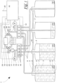
- a device 1 according to figure 1 has several containers 2, which are partially filled with a liquid 3, in particular water.
- the number of containers 2 shown is only to be understood as an example.
- a remaining volume of the container 2 is filled with a gas 4, in particular nitrogen or carbon dioxide.
- This gas 4 serves as a buffer volume in order to replace liquid 3 taken from the container 2 in terms of volume. Since the gas 4 has a density that is lower by a factor of about 1000 than the liquid 3, its absolute heat capacity compared to the liquid 3 is negligibly small.
- the containers 2 have connections 5 on the upper side, via which the material is transported into and out of the containers 2 .
- These connections 5 have a dip tube 6 which runs from the connection 5 to near a bottom 7 of the container 2 . This ensures that a lower end 8 of the immersion tube 6 is always immersed in the liquid 3 , as a result of which essentially only the liquid 3 is transported in the immersion tube 6 .
- the dip tube 6 is connected to a liquid line 9, via which the liquid 3 is supplied to the container 2 or removed from it.
- a gas line 10 is also flanged on the top, which is connected to all containers 3 in the same way.
- This gas line 10 provides for a corresponding volume exchange of the gas 4.
- This volume exchange takes place passively, i.e. without active elements such as pumps or the like.
- the gas 4 is thereby displaced from the container 2 which is just being filled and passed via the gas line 10 into that container 2 which is just being emptied.
- the gas line 10 could also be pressurized via appropriate valves in order to thereby indirectly displace the liquid 3 from the respective container 2. In this way, the active pumping system is shifted from the liquid circuit to the gas circuit.
- the liquid lines 9 are each connected to a flow 13 or a return 14 of a heating system 15 via a flow multiplexer 11 and a return multiplexer 12 .
- This heating system 15 is in the figure 1 shown only schematically as a radiator. In practice, several heating elements are provided here, which are connected in parallel or in series, depending on the arrangement, the heating elements then also being able to be subjected to the liquid 3 in a targeted manner by means of corresponding throttle valves.
- the flow multiplexer 11 and return multiplexer 12 are formed from individual valves 16, the one side with one of the liquid lines 9 and the output side either with the flow 13 or with the Return 14 are connected. Only one of these valves 16 is ever opened, as a result of which one of the containers 2 is selected as the source of the liquid 3 and another container 2 is selected as the sink for the liquid 3 .
- This liquid flow is generated and maintained by a pump 17 provided in the flow 13 .
- the pump 17 can also be provided in the return line 14 .
- the flow multiplexer (11) or the return multiplexer (12) can also be designed as a more complex valve without requiring a large number of individual valves (16).
- this multiplexer (11, 12) can be designed in the form of a disc with at least one opening, which optionally connects various connecting lines to the containers (2) to a common line.
- a specific container (2) can then be selected by turning the disk.
- the rotating disk can also be replaced by a slidable shaft which has at least one through-channel.
- One of the containers (2) can then be optionally selected by moving the shaft.
- the illustrated and described embodiment of the device 1 means that no cooled liquid 2 has to be refilled to remove the liquid 3 from the container 2 in order to maintain the volume. This also eliminates the need for a layer between in the container 2 provide hot and cold liquid 3, which can lead to significant heat losses.
- a controller 18 is provided in order to correctly control the valves 16 of the flow multiplexer 11 and return multiplexer 12 .
- This controller 18 is operatively connected to a pressure sensor 19 which is provided on the suction side of the pump 17 .
- the pressure determined by the pressure sensor 19 can thus be used as a measure of the fill level of the liquid 3 in the respectively selected container 2 .
- Another pressure sensor 20 which is also connected to the controller 18 , is located in the return line 14 .
- This pressure sensor 20 detects the back pressure of that container 2 which is selected by the return multiplexer 12 for filling. The higher the fill level in this container 2, the higher the back pressure that is detected by the pressure sensor 20 will be. The pressure sensor 20 thus supplies a measure of the fill level of the container 2 to be filled.
- the controller 18 monitors the pressure sensors 19, 20 in order to prevent the container 2 from which the liquid 3 is taken from running empty or the container 2 into which the liquid 3 is filled from overflowing.
- the container 2 with at least one Be equipped with a float-operated valve to prevent it from draining and overflowing.
- the controller 18 is also connected to temperature sensors 21 provided in each of the tanks 2 . These temperature sensors 21 determine the temperatures of the liquid 3 stored in the respective container 2. Alternatively, it is also possible to integrate the temperature sensors 21 in the flow 13 and/or return 14. In this case, the controller 18 only receives information about the temperature of the stored liquid 3 while it is being filled into the container 2 or removed from it.
- the controller 18 In order to determine the respective liquid temperature in the containers 2 at other times, the controller 18 must then calculate the temperature profile of the liquid 3 in the containers 2 on the basis of the data obtained from the temperature sensors 21 by using a model for heat losses, taking into account the temperatures of all neighboring container 2 is calculated. This results in a considerable simplification of the sensor system at the expense of the computing effort in the controller 18 and the accuracy of the temperature determination of the liquids 3.
- the controller 18 receives information about the temperature level requested by the heating system 15 via a request line 22 and compares this temperature level with the temperatures the container 2, which are transmitted from the temperature sensors 21 to the controller 18.
- Container 2, whose temperature is below the required temperature, is not taken into account. From those containers 2 that meet the requirement level is preferably dated Controller 18 selected the one that has the lowest just sufficient temperature. In this way, the temperature levels present in the containers 2 are optimally used to meet the respective temperature requirement.
- the flow 13 and return 14 are connected to the heating system 15 via three-way valves 23 .
- These three-way valves 23 enable a bypass to a heat source 24, with parallel liquid flows through the heating system 15 and the heat source 24 being possible. It can be freely selected whether the heating system 15 is supplied with liquid 3 from the containers 2 in addition to the heat source 24 , or whether part of the liquid 3 heated by the heat source 24 is stored in the containers 2 . This essentially depends on the heat requirement of the heating system 15 and the available amount of heat from the heat source 24 .
- the three-way valves 23 are also controlled by the controller 18 for this purpose. The controller 18 checks the heat requirement using temperature sensors 25, 26 in the flow 13 and return 14 and then adjusts the three-way valves 23 according to the heat requirements.
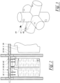
- the figure 2 shows a sectional view of a detail of the device 1 according to FIG figure 1 , where the same reference symbols denote the same parts.
- the containers 2 consist of a tensile but shape-changing plastic film 30, which is not shown by a Net worn and suspended from a frame 31.
- the purpose of the plastic film 30 is to realize a structure for the container 2 that is as light as possible and easy to transport.
- the frame 31 consists of support feet 32 which are provided between containers 2 and support the weight of adjacent containers 2, respectively.
- Several of the containers 2 can also be provided between the support feet 32 in order to reduce the container volume in this way.
- These support feet 32 are connected via connectors 33 to crossbars 34 which form a square above each container 2, for example.
- the containers 2 are then held hanging by means of ropes 35 on these crossbars 34 .
- loops that are held on the crossbars 34 could also be formed on the containers 2 .
- the figure 3 12 shows a spatial representation of a connector 33 which can be provided at each connection point between the support feet 32 and the crossbars 34.
- FIG. This connector 33 consists essentially of six cylinders 40, two of which are arranged axially aligned. These pairs of axially aligned cylinders 40 are each arranged perpendicularly to one another, resulting in connections for all three orthogonal spatial directions.
- the cylinders 40 are dimensioned in such a way that they can be inserted into the tubular support feet 32 or crossbars 34 . This results in a firm connection of the frame 31.
- connection of the support feet 32 and crossbars 34 to the connector 33 can be realized by means of spring-biased balls 41 .
- the support feet 32 and crossbars 34 have corresponding indentations 42, which figure 2 you can see.
- corresponding threaded holes could be provided in the connector 33, into which screws to secure the support feet 32 or the crossbars 34 engage.
Landscapes
- Engineering & Computer Science (AREA)
- Mechanical Engineering (AREA)
- Physics & Mathematics (AREA)
- Thermal Sciences (AREA)
- General Engineering & Computer Science (AREA)
- Filling Or Discharging Of Gas Storage Vessels (AREA)
- Secondary Cells (AREA)
- Separation By Low-Temperature Treatments (AREA)
Claims (12)
- Dispositif de stockage d'énergie thermique au moyen d'au moins un liquide (3) qui est prévu dans des récipients (2) qui peuvent contenir l'au moins un liquide (3) et au moins un gaz (4) de compensation de volume, les récipients (2) étant en communication côté gaz et pouvant être reliés côté liquide sélectivement à au moins une voie aller (13) et au moins une voie retour (14) par le biais de conduites de liquide (9) pouvant être fermées par des vannes (16) de sorte que les récipients (2) puissent être utilisés sélectivement comme source de chaleur ou dissipateur de chaleur, les vannes (16) formant un multiplexeur aller (11) et/ou retour (12), caractérisé en ce que l'au moins un conteneur (2) est suspendu à au moins un cadre (31).
- Dispositif selon la revendication 1, caractérisé en ce qu'au moins deux des récipients (2) sont en communication côté gaz par le biais d'au moins une conduite de gaz (10).
- Dispositif selon la revendication 2, caractérisé en ce que l'au moins une conduite de gaz (10) forme un système fermé avec les récipients (2).
- Dispositif selon l'une au moins des revendications 1 à 3, caractérisé en ce que l'une des conduites de liquide (9), par laquelle le récipient (2) est sélectivement rempli avec l'au moins un liquide (3) ou vidé de celui-ci, aboutit à chacun des récipients (2).
- Dispositif selon l'une au moins des revendications 1 à 4, caractérisé en ce que l'au moins un gaz (4) est séparé de l'au moins un liquide (3) par au moins une paroi de récipient de forme variable.
- Dispositif selon la revendication 5, caractérisé en ce qu'au moins un capteur (19, 20, 21) est prévu dans la voie aller (13) et/ou la voie retour (14).
- Dispositif selon l'une au moins des revendications 1 à 6, caractérisé en ce que l'au moins un cadre (31) a une structure modulaire et comporte des pieds de support (32) qui peuvent supporter un poids de récipients adjacents (2).
- Dispositif l'une au moins des revendications 1 à 7, caractérisé en ce que l'au moins un cadre (31) est maintenu assemblé au moyen de connecteurs enfichables (33) .
- Dispositif selon l'une au moins des revendications 1 à 8, caractérisé en ce que l'au moins un cadre (31) peut supporter des récipients (2) qui sont disposés les uns au-dessus des autres et qui sont au moins partiellement découplés du point de vue hydrostatique.
- Dispositif selon la revendication 9, caractérisé en ce que la somme des volumes de stockage des récipients (2) est dimensionnée de manière à être supérieure, d'au moins le volume de remplissage maximum d'un des récipients (2), à la quantité de l'au moins un liquide (3) à stocker.
- Dispositif selon l'une au moins des revendications 1 à 10, caractérisé en ce que l'au moins un gaz (4) est biologiquement inerte.
- Dispositif selon l'une au moins des revendications 1 à 11, caractérisé en ce qu'au moins un contrôleur (18) est prévu qui surveille l'état de remplissage des récipients (2) et commande au moins une des vannes (16) de manière à empêcher un débordement et/ou un vidage des récipients (2).
Applications Claiming Priority (2)
| Application Number | Priority Date | Filing Date | Title |
|---|---|---|---|
| DE202016006835.1U DE202016006835U1 (de) | 2016-11-07 | 2016-11-07 | Vorrichtung zum Speichern von thermischer Energie |
| PCT/EP2017/001290 WO2018082815A2 (fr) | 2016-11-07 | 2017-11-07 | Dispositif de stockage d'énergie thermique |
Publications (4)
| Publication Number | Publication Date |
|---|---|
| EP3535538A2 EP3535538A2 (fr) | 2019-09-11 |
| EP3535538B1 true EP3535538B1 (fr) | 2023-06-07 |
| EP3535538C0 EP3535538C0 (fr) | 2023-06-07 |
| EP3535538B8 EP3535538B8 (fr) | 2023-07-26 |
Family
ID=60450568
Family Applications (1)
| Application Number | Title | Priority Date | Filing Date |
|---|---|---|---|
| EP17803776.8A Active EP3535538B8 (fr) | 2016-11-07 | 2017-11-07 | Dispositif de stockage d'énergie thermique |
Country Status (5)
| Country | Link |
|---|---|
| EP (1) | EP3535538B8 (fr) |
| DE (1) | DE202016006835U1 (fr) |
| ES (1) | ES2950444T3 (fr) |
| PL (1) | PL3535538T3 (fr) |
| WO (1) | WO2018082815A2 (fr) |
Families Citing this family (3)
| Publication number | Priority date | Publication date | Assignee | Title |
|---|---|---|---|---|
| BE1026308B1 (nl) * | 2018-10-08 | 2019-12-18 | Vero Duco Nv | Thermisch systeem en werkwijze om deze aan te sturen |
| NO20200447A1 (en) * | 2020-04-14 | 2021-10-15 | Kyoto Group As | Thermal Energy Storage Device |
| NO348850B1 (en) * | 2023-07-07 | 2025-06-23 | Kyoto Group As | Flow system |
Family Cites Families (10)
| Publication number | Priority date | Publication date | Assignee | Title |
|---|---|---|---|---|
| DE2923480A1 (de) * | 1979-06-09 | 1980-12-18 | Erno Raumfahrttechnik Gmbh | Verfahren zur speicherung von insbesondere niedertemperatur-waerme |
| DE2943797C2 (de) * | 1979-10-30 | 1984-05-17 | Otmar Dipl.-Ing. 8000 München Schäfer | Verfahren und Vorrichtung zum abwechselnden Heizen und Kühlen eines Wärmetauschers |
| DE3145197C2 (de) * | 1981-11-13 | 1986-01-02 | Otmar Dipl.-Ing. 8000 München Schäfer | Wärmespeicherbehälter für eine Heiz-Kühl-Anlage mit Wärmerückgewinnung |
| ES2036677T3 (es) * | 1987-04-14 | 1993-06-01 | Uwe Rockenfeller | Sistema de acumulacion de energia quimica. |
| JP2003240464A (ja) * | 2002-02-18 | 2003-08-27 | Energy Support Corp | 蓄熱装置 |
| DE202009018043U1 (de) * | 2009-03-09 | 2010-12-02 | Rawema Countertrade Handelsgesellschaft Mbh | Wärmespeichersystem |
| DE102011000655B4 (de) * | 2010-02-11 | 2023-02-23 | Uwe Athmann | Wärmetransportsystem |
| DE102011053349B4 (de) * | 2011-09-07 | 2022-02-24 | Deutsches Zentrum für Luft- und Raumfahrt e.V. | Wärmespeichersystem und Verfahren zum Speichern von Wärme |
| DE102011055014A1 (de) * | 2011-11-03 | 2013-05-08 | Gerald Weindel | Energiespeicher zur Speicherung thermischer Energie |
| WO2015022693A1 (fr) | 2013-08-15 | 2015-02-19 | Chromagen Agricultural Cooperative Society Ltd. | Chaudière extensible |
-
2016
- 2016-11-07 DE DE202016006835.1U patent/DE202016006835U1/de not_active Expired - Lifetime
-
2017
- 2017-11-07 WO PCT/EP2017/001290 patent/WO2018082815A2/fr not_active Ceased
- 2017-11-07 ES ES17803776T patent/ES2950444T3/es active Active
- 2017-11-07 PL PL17803776.8T patent/PL3535538T3/pl unknown
- 2017-11-07 EP EP17803776.8A patent/EP3535538B8/fr active Active
Also Published As
| Publication number | Publication date |
|---|---|
| DE202016006835U1 (de) | 2018-02-09 |
| PL3535538T3 (pl) | 2023-10-30 |
| EP3535538B8 (fr) | 2023-07-26 |
| EP3535538A2 (fr) | 2019-09-11 |
| WO2018082815A3 (fr) | 2018-07-26 |
| WO2018082815A2 (fr) | 2018-05-11 |
| EP3535538C0 (fr) | 2023-06-07 |
| ES2950444T3 (es) | 2023-10-10 |
Similar Documents
| Publication | Publication Date | Title |
|---|---|---|
| AT510440B1 (de) | Fluidspeicher | |
| DE102017111492B4 (de) | Vorrichtung zur Speicherung von temperierbaren Fluiden | |
| CH628414A5 (de) | Verfahren und vorrichtung zur verlustarmen speicherung von waermeenergie in einem waermespeicher und zur verlustarmen entnahme der gespeicherten waermeenergie. | |
| EP0574954A2 (fr) | Chauffe-eau solaire avec stockage intégré | |
| AT514997A1 (de) | Modulare Absorptionskältemaschine in Plattenbauweise | |
| EP2963350A1 (fr) | Systeme destine a un fonctionnement a economie d'energie d'un echangeur thermique utilise ou exploite par intermittence dans un systeme de conduites, en particulier destine au chauffage de l'eau potable | |
| EP4150203B1 (fr) | Système de stockage et de récupération d'énergie | |
| DE102012218634A1 (de) | Speichereinrichtung zur Zwischenspeicherung von thermischer Energie sowie Verfahren zum Betreiben einer Speichereinrichtung | |
| DE19654037C1 (de) | Anlage zur Gewinnung von Wärme aus Solarenergie | |
| EP3535538A2 (fr) | Dispositif de stockage d'énergie thermique | |
| EP1906101B1 (fr) | Agencement de stockage et procédé de transfert pour énergie calorifique | |
| DE102015224723A1 (de) | Vorrichtung und Verfahren zur Wärmerückgewinnung aus Abwasser eines mit Warmwasser arbeitenden Geräts | |
| DE2721173A1 (de) | Waermespeicher | |
| DE2804748B1 (de) | Waerme-isolierter Behaelter fuer warmes Wasser o.a. Fluessigkeiten | |
| DE102005059029A1 (de) | Verfahren und Speicher zur Langzeitspeicherung von Wärme | |
| DE102015117848A1 (de) | Fluidsystem und Verfahren zum Steuern eines Fluidsystems | |
| EP3076111B1 (fr) | Système fluidique et procédé de commande d'un système fluidique | |
| DE19846364A1 (de) | Wärmeschichtspeicher und Verfahren zum Betreiben des Speichers | |
| CH703413A1 (de) | Heizanlage mit Wärmepumpe. | |
| DE10320569B4 (de) | Schichtwärmespeicher | |
| AT523320B1 (fr) | ||
| DE3145636A1 (de) | Heizanlage zur warmwasserbereitung | |
| DE2917231A1 (de) | Vorrichtung zum speichern von waerme | |
| DE3208582C2 (de) | Anordnung zur Beheizung von Gebäuden | |
| AT10232U1 (de) | Heizungsanlage mit mindestens einer wärmequelle |
Legal Events
| Date | Code | Title | Description |
|---|---|---|---|
| STAA | Information on the status of an ep patent application or granted ep patent |
Free format text: STATUS: UNKNOWN |
|
| STAA | Information on the status of an ep patent application or granted ep patent |
Free format text: STATUS: THE INTERNATIONAL PUBLICATION HAS BEEN MADE |
|
| PUAI | Public reference made under article 153(3) epc to a published international application that has entered the european phase |
Free format text: ORIGINAL CODE: 0009012 |
|
| STAA | Information on the status of an ep patent application or granted ep patent |
Free format text: STATUS: REQUEST FOR EXAMINATION WAS MADE |
|
| 17P | Request for examination filed |
Effective date: 20190605 |
|
| AK | Designated contracting states |
Kind code of ref document: A2 Designated state(s): AL AT BE BG CH CY CZ DE DK EE ES FI FR GB GR HR HU IE IS IT LI LT LU LV MC MK MT NL NO PL PT RO RS SE SI SK SM TR |
|
| AX | Request for extension of the european patent |
Extension state: BA ME |
|
| DAV | Request for validation of the european patent (deleted) | ||
| DAX | Request for extension of the european patent (deleted) | ||
| STAA | Information on the status of an ep patent application or granted ep patent |
Free format text: STATUS: EXAMINATION IS IN PROGRESS |
|
| 17Q | First examination report despatched |
Effective date: 20210406 |
|
| GRAP | Despatch of communication of intention to grant a patent |
Free format text: ORIGINAL CODE: EPIDOSNIGR1 |
|
| STAA | Information on the status of an ep patent application or granted ep patent |
Free format text: STATUS: GRANT OF PATENT IS INTENDED |
|
| INTG | Intention to grant announced |
Effective date: 20221104 |
|
| GRAS | Grant fee paid |
Free format text: ORIGINAL CODE: EPIDOSNIGR3 |
|
| GRAA | (expected) grant |
Free format text: ORIGINAL CODE: 0009210 |
|
| STAA | Information on the status of an ep patent application or granted ep patent |
Free format text: STATUS: THE PATENT HAS BEEN GRANTED |
|
| AK | Designated contracting states |
Kind code of ref document: B1 Designated state(s): AL AT BE BG CH CY CZ DE DK EE ES FI FR GB GR HR HU IE IS IT LI LT LU LV MC MK MT NL NO PL PT RO RS SE SI SK SM TR |
|
| REG | Reference to a national code |
Ref country code: GB Ref legal event code: FG4D Free format text: NOT ENGLISH |
|
| REG | Reference to a national code |
Ref country code: CH Ref legal event code: EP Ref country code: AT Ref legal event code: REF Ref document number: 1576270 Country of ref document: AT Kind code of ref document: T Effective date: 20230615 |
|
| GRAT | Correction requested after decision to grant or after decision to maintain patent in amended form |
Free format text: ORIGINAL CODE: EPIDOSNCDEC |
|
| REG | Reference to a national code |
Ref country code: DE Ref legal event code: R096 Ref document number: 502017014888 Country of ref document: DE |
|
| REG | Reference to a national code |
Ref country code: CH Ref legal event code: PK Free format text: BERICHTIGUNGEN Ref country code: CH Ref legal event code: PK Free format text: BERICHTIGUNG B8 |
|
| RAP4 | Party data changed (patent owner data changed or rights of a patent transferred) |
Owner name: SCHILLING, GERHARD Owner name: KUFFER, ROLAND |
|
| RIN2 | Information on inventor provided after grant (corrected) |
Inventor name: SCHILLING, GERHARD Inventor name: KUFFER, ROLAND |
|
| U01 | Request for unitary effect filed |
Effective date: 20230705 |
|
| U07 | Unitary effect registered |
Designated state(s): AT BE BG DE DK EE FI FR IT LT LU LV MT NL PT SE SI Effective date: 20230712 |
|
| REG | Reference to a national code |
Ref country code: NO Ref legal event code: T2 Effective date: 20230607 |
|
| REG | Reference to a national code |
Ref country code: LT Ref legal event code: MG9D |
|
| REG | Reference to a national code |
Ref country code: ES Ref legal event code: FG2A Ref document number: 2950444 Country of ref document: ES Kind code of ref document: T3 Effective date: 20231010 |
|
| PG25 | Lapsed in a contracting state [announced via postgrant information from national office to epo] |
Ref country code: RS Free format text: LAPSE BECAUSE OF FAILURE TO SUBMIT A TRANSLATION OF THE DESCRIPTION OR TO PAY THE FEE WITHIN THE PRESCRIBED TIME-LIMIT Effective date: 20230607 Ref country code: HR Free format text: LAPSE BECAUSE OF FAILURE TO SUBMIT A TRANSLATION OF THE DESCRIPTION OR TO PAY THE FEE WITHIN THE PRESCRIBED TIME-LIMIT Effective date: 20230607 Ref country code: GR Free format text: LAPSE BECAUSE OF FAILURE TO SUBMIT A TRANSLATION OF THE DESCRIPTION OR TO PAY THE FEE WITHIN THE PRESCRIBED TIME-LIMIT Effective date: 20230908 |
|
| U20 | Renewal fee for the european patent with unitary effect paid |
Year of fee payment: 7 Effective date: 20231122 |
|
| PG25 | Lapsed in a contracting state [announced via postgrant information from national office to epo] |
Ref country code: SK Free format text: LAPSE BECAUSE OF FAILURE TO SUBMIT A TRANSLATION OF THE DESCRIPTION OR TO PAY THE FEE WITHIN THE PRESCRIBED TIME-LIMIT Effective date: 20230607 |
|
| PG25 | Lapsed in a contracting state [announced via postgrant information from national office to epo] |
Ref country code: IS Free format text: LAPSE BECAUSE OF FAILURE TO SUBMIT A TRANSLATION OF THE DESCRIPTION OR TO PAY THE FEE WITHIN THE PRESCRIBED TIME-LIMIT Effective date: 20231007 |
|
| PG25 | Lapsed in a contracting state [announced via postgrant information from national office to epo] |
Ref country code: SM Free format text: LAPSE BECAUSE OF FAILURE TO SUBMIT A TRANSLATION OF THE DESCRIPTION OR TO PAY THE FEE WITHIN THE PRESCRIBED TIME-LIMIT Effective date: 20230607 Ref country code: SK Free format text: LAPSE BECAUSE OF FAILURE TO SUBMIT A TRANSLATION OF THE DESCRIPTION OR TO PAY THE FEE WITHIN THE PRESCRIBED TIME-LIMIT Effective date: 20230607 Ref country code: RO Free format text: LAPSE BECAUSE OF FAILURE TO SUBMIT A TRANSLATION OF THE DESCRIPTION OR TO PAY THE FEE WITHIN THE PRESCRIBED TIME-LIMIT Effective date: 20230607 Ref country code: IS Free format text: LAPSE BECAUSE OF FAILURE TO SUBMIT A TRANSLATION OF THE DESCRIPTION OR TO PAY THE FEE WITHIN THE PRESCRIBED TIME-LIMIT Effective date: 20231007 |
|
| REG | Reference to a national code |
Ref country code: DE Ref legal event code: R097 Ref document number: 502017014888 Country of ref document: DE |
|
| PLBE | No opposition filed within time limit |
Free format text: ORIGINAL CODE: 0009261 |
|
| STAA | Information on the status of an ep patent application or granted ep patent |
Free format text: STATUS: NO OPPOSITION FILED WITHIN TIME LIMIT |
|
| 26N | No opposition filed |
Effective date: 20240308 |
|
| REG | Reference to a national code |
Ref country code: CH Ref legal event code: PL |
|
| PG25 | Lapsed in a contracting state [announced via postgrant information from national office to epo] |
Ref country code: MC Free format text: LAPSE BECAUSE OF FAILURE TO SUBMIT A TRANSLATION OF THE DESCRIPTION OR TO PAY THE FEE WITHIN THE PRESCRIBED TIME-LIMIT Effective date: 20230607 |
|
| PG25 | Lapsed in a contracting state [announced via postgrant information from national office to epo] |
Ref country code: CH Free format text: LAPSE BECAUSE OF NON-PAYMENT OF DUE FEES Effective date: 20231130 |
|
| PG25 | Lapsed in a contracting state [announced via postgrant information from national office to epo] |
Ref country code: MC Free format text: LAPSE BECAUSE OF FAILURE TO SUBMIT A TRANSLATION OF THE DESCRIPTION OR TO PAY THE FEE WITHIN THE PRESCRIBED TIME-LIMIT Effective date: 20230607 Ref country code: CH Free format text: LAPSE BECAUSE OF NON-PAYMENT OF DUE FEES Effective date: 20231130 |
|
| U20 | Renewal fee for the european patent with unitary effect paid |
Year of fee payment: 8 Effective date: 20241122 |
|
| PG25 | Lapsed in a contracting state [announced via postgrant information from national office to epo] |
Ref country code: CY Free format text: LAPSE BECAUSE OF FAILURE TO SUBMIT A TRANSLATION OF THE DESCRIPTION OR TO PAY THE FEE WITHIN THE PRESCRIBED TIME-LIMIT; INVALID AB INITIO Effective date: 20171107 |
|
| PG25 | Lapsed in a contracting state [announced via postgrant information from national office to epo] |
Ref country code: HU Free format text: LAPSE BECAUSE OF FAILURE TO SUBMIT A TRANSLATION OF THE DESCRIPTION OR TO PAY THE FEE WITHIN THE PRESCRIBED TIME-LIMIT; INVALID AB INITIO Effective date: 20171107 |
|
| U20 | Renewal fee for the european patent with unitary effect paid |
Year of fee payment: 9 Effective date: 20251126 |
|
| PGFP | Annual fee paid to national office [announced via postgrant information from national office to epo] |
Ref country code: GB Payment date: 20251125 Year of fee payment: 9 |
|
| PGFP | Annual fee paid to national office [announced via postgrant information from national office to epo] |
Ref country code: NO Payment date: 20251127 Year of fee payment: 9 |
|
| PGFP | Annual fee paid to national office [announced via postgrant information from national office to epo] |
Ref country code: TR Payment date: 20251030 Year of fee payment: 9 |
|
| PGFP | Annual fee paid to national office [announced via postgrant information from national office to epo] |
Ref country code: IE Payment date: 20251125 Year of fee payment: 9 Ref country code: CZ Payment date: 20251024 Year of fee payment: 9 |
|
| PGFP | Annual fee paid to national office [announced via postgrant information from national office to epo] |
Ref country code: PL Payment date: 20251024 Year of fee payment: 9 |
|
| PGFP | Annual fee paid to national office [announced via postgrant information from national office to epo] |
Ref country code: ES Payment date: 20251201 Year of fee payment: 9 |