EP3535543B1 - Contenant de charge de propulsion - Google Patents
Contenant de charge de propulsion Download PDFInfo
- Publication number
- EP3535543B1 EP3535543B1 EP17790818.3A EP17790818A EP3535543B1 EP 3535543 B1 EP3535543 B1 EP 3535543B1 EP 17790818 A EP17790818 A EP 17790818A EP 3535543 B1 EP3535543 B1 EP 3535543B1
- Authority
- EP
- European Patent Office
- Prior art keywords
- charge container
- modular cartridge
- charge
- cartridge case
- proceeding
- Prior art date
- Legal status (The legal status is an assumption and is not a legal conclusion. Google has not performed a legal analysis and makes no representation as to the accuracy of the status listed.)
- Active
Links
Images
Classifications
-
- F—MECHANICAL ENGINEERING; LIGHTING; HEATING; WEAPONS; BLASTING
- F42—AMMUNITION; BLASTING
- F42B—EXPLOSIVE CHARGES, e.g. FOR BLASTING, FIREWORKS, AMMUNITION
- F42B5/00—Cartridge ammunition, e.g. separately-loaded propellant charges
- F42B5/38—Separately-loaded propellant charges, e.g. cartridge bags
-
- F—MECHANICAL ENGINEERING; LIGHTING; HEATING; WEAPONS; BLASTING
- F42—AMMUNITION; BLASTING
- F42B—EXPLOSIVE CHARGES, e.g. FOR BLASTING, FIREWORKS, AMMUNITION
- F42B5/00—Cartridge ammunition, e.g. separately-loaded propellant charges
- F42B5/02—Cartridges, i.e. cases with charge and missile
- F42B5/18—Caseless ammunition; Cartridges having combustible cases
- F42B5/192—Cartridge cases characterised by the material of the casing wall
-
- F—MECHANICAL ENGINEERING; LIGHTING; HEATING; WEAPONS; BLASTING
- F42—AMMUNITION; BLASTING
- F42B—EXPLOSIVE CHARGES, e.g. FOR BLASTING, FIREWORKS, AMMUNITION
- F42B5/00—Cartridge ammunition, e.g. separately-loaded propellant charges
- F42B5/26—Cartridge cases
- F42B5/30—Cartridge cases of plastics, i.e. the cartridge-case tube is of plastics
Definitions
- the invention relates to a charge container device, for use as a charge for propelling munitions, more specifically related to the area of modular charge containers.
- a projectiles range may be achieved by utilising an explosive train sequence, which may comprise an igniter, a primer with an intermediate explosive and an output charge.
- the explosive train serves to take a small energetic event and amplify the output as it moves through the explosive train.
- an explosive train sequence is often used in the launching of munitions, whether direct or indirect; to propel a shell over a distance, often considering a minimum launch distance to prevent injury to own troops or large distances to reach long range.
- an ignition means is incorporated alongside a charge, with additional charges being added or subtracted depending on the distance the shell is to travel.
- an explosive train sequence may be carried out modularly; this can be done in a number of ways depending on the system used and various other user requirements or conditions (e.g. variations of distances where opposition forces are engaged).
- One example of the use of a combination of charges to achieve a launch distance is to load modular charges individually into the breech until the desired total charge is achieved.
- Each charge contains an energetic material and is made from a rigid, combustible case and may be of different sizes, which correspond to a predetermined distance they are able to propel a shell.
- Each charge comprises a recessed and extruded portion to allow them to fit together as they are loaded into the breech in order to prevent adverse movement.
- the ignition means on the case e.g. an igniter pad
- an igniter pad causes an explosive train sequence to begin, which continues through the charges until the force expels the shell from the barrel of the weapon.
- This method suffers as the explosives train is formed by utilising the individual charges loosely coupled together utilising the recess/extrusions provided, making rapid movement or formation of a desired charge time consuming.
- the charges themselves are also formed from a rigid outer case containing loose energetic material and as a result hold no flexibility for rapid change of energetic material quantity if needed.
- combustible in this context refers to the fact that the bags are fully consumed following burning, rather than providing further energetic output.
- These combustible bags are filled with a set quantity of energetic material, relating to different distances the shell is to be launched.
- These bags may be placed into a single, larger combustible bag (e.g. cotton), with an igniter pad at the base wherein the total number of bags contained within relate to a specific distance.
- the number of required bags is placed in an initial combustible bag, which comprises a number of ties that may be brought up around the combustible bags to hold them in place.
- the larger bag or combustible bag chain When required to be used the larger bag or combustible bag chain is taken and placed in its entirety into the breech. Upon firing the ignition begins the explosive train, which travels up through the bags, firing the shell over the desired distance and combusting the bag in the process, allowing the breech to be clear for the next shell and charge.
- This method has significant cost savings and flexibility as the use of a large single bag to contain smaller charges means that a single bag, relating to a distance can be moved around and is not costly to produce. Its lack of rigid structure does however make handling difficult and a cotton material can be prone to snagging and tears. Further to this the adding of single bags to a larger container can be subject to human error and mistakes, such as the addition of the wrong charge or omission of a charge, may cause a launch to overshoot or undershoot its target. These human errors may increase during periods of high stress, such as conflict.
- a final example involves a single full length master combustible bag with individual "elongate sticks" of energetic material contained in individual full length combustible bags.
- the sticks, once in their combustible bags are arranged to run the full length of the single master combustible bag.
- an ignition pad at the bottom of the single master combustible bag is struck and causes the "elongate sticks" of energetic material to react and burn from the base of the master bag up through the "elongate stick".
- the invention herein aims to address the issues presented in the background prior art by solving issues in robustness, flexibility and usability.
- a charge container device having a volume suitable to substantially fill a barrel chamber, said charge container device is formed from a substantially rigid and combustible material, wherein said charge container device comprises at least one wall to define a cavity for the retention of at least one cartridge case, said at least one cartridge case comprising an energetic material, wherein said at least one cartridge case is arranged in a stacked formation within said charge container, the charge container device further comprising a base portion and a top portion, wherein the top portion comprises an aperture to allow for expulsion of energy and the base portion comprising an ignition means.
- the barrel chamber is the portion of barrel which has a volume in which the propellant is located.
- the volume is between the breech and the rear face of the projectile, this will be standard for each barrel type.
- the charge container may preferably be produced as a single unit, whose volume, that is length and diameter, may be selected depending on the breech it is designed to fit, such that in use the charge container device substantially fills the barrel chamber.
- the internal cavity may provide a predefined volume to specifically allow modular cartridge cases with standard amounts and type of energetic material.
- the charge container may be constructed from a substantially rigid material, such that in use the material is capable of supporting the mass of propellant without buckling or tearing.
- the material is a combustible material, such as, for example, an impregnated paper or card, but preferably a Nitrocellulose and Kraft mix, which allows the charge container to be handled easily, however will combust and during use leaving substantially no residue to prevent the need to clean the barrel between uses or remove debris prior to loading a new shell or charge container device into the breech.
- a combustible material such as, for example, an impregnated paper or card, but preferably a Nitrocellulose and Kraft mix, which allows the charge container to be handled easily, however will combust and during use leaving substantially no residue to prevent the need to clean the barrel between uses or remove debris prior to loading a new shell or charge container device into the breech.
- Substantially filling the breech of a gun allows a single charge container to be used without significant loss of energy during firing, however providing the flexibility of having its overall energetic output being determined by the amount of cartridge cases contained within.
- a first fixed cartridge case at the charge container device's base portion to ensure the charge container is capable in use of launching a projectile to a minimum distance and one or more further cartridge cases.
- the use of a fixed cartridge case provides a safety mechanism that there is sufficient propellant to launch a projectile to a distance that is safe from the operators.
- the charge container comprises a plurality of further cartridge cases, which may be added or removed from the charge container depending on the desired launch distance.
- the plurality of cartridge cases may be stacked one on top the other, as additional cartridge cases are added, so that they are horizontally stacked, such that they are coaxially aligned.
- the cartridge cases may comprise a base and a top and may be filled with an energetic material, in the form of pellets or grains.
- the cartridge cases may be reversibly attached to additional cartridge cases, for example by a hook and loop arrangement; alternatively the base may comprise a recessed portion and the top may comprise an extruded portion in order to facilitate the linking or cartridge cases by the insertion of an extruded surface of a top portion into the recessed portion of the base of a further cartridge case.
- both base and top of a cartridge case may be substantially flat, however with an abrasive surface or a surface with raised portions to increase the co-efficiency of the two surfaces in order that when a top portion and a base portion are in contact they are sufficiently resilient to movement.
- the cartridge case may be formed from a rigid or flexible material, however in a preferred embodiment the cartridge case may be a flexible material such as cotton or polyester, as it is cheaper and faster to manufacture as well as providing a simpler system to add the energetic material.
- An igniter pad may also be included at the base of each individual cartridge case to be used as a means of igniting the energetic material of individual cartridge cases, providing a greater means of flexibility.
- cartridge cases may be shaped to provide a central void, to accept the insertion of a central core igniter, allowing a means to ignite the energetic material in a more uniform manner, rather than from the base upward.
- the one or more further cartridge cases may be housed in the cavity, preferably being reversibly attached to the wall of the charge container by a fixing means.
- This reversible means may comprise a hook and loop attachment (e.g. Velco) or in a preferred arrangement the cartridge case may be held in place utilising spacers attached to the internal wall of the cavity.
- the spacers may hold each further cartridge case under friction and advantageously ensure a space between the external wall of the further cartridge case and the internal wall of the charge container between 1mm and 10mm, said space allowing for the propagation of a flame front either side of said further cartridge case during the explosive train.
- spacers provides a more uniform explosive energy output and may provide a flash path for thermal output and flame propagation, allowing the device to utilise the areas created by the spacers to ensure even ignition of the cartridge case and energetic material.
- the energetic material within the fixed cartridge and one or more further cartridge cases is propellant.
- This energetic material may be in the form of pellets, granules or powder.
- the base portion of the charge container may comprise an igniter pad, said igniter pad being present to aid in the initiation of the explosive train and may contain an energetic material such as a propellant or pyrotechnic.
- the base pad may provide the means for striking a central core igniter running the length of the charge container in order to provide a uniform ignition to all the cartridge cases contained within the cavity.
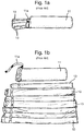
- a charge bag 11 with a number of elongate charges 13 inserted therein.
- the elongate charges 13 are held in position, to reduce movement, by a strap tie 11a.
- the elongate charges 13 may be easily added to or subtracted from the charge bag 11 by releasing the hold of the strap tie 11a, pulling out one or more elongate charges 13 and optionally adding a different elongate charge 13 to the charge bag and re-securing the strap tie 11a.
- the amount of charge being selected depending on the distance the projectile is desired to travel.
- a calm, well lit scenario it is a simple procedure to group the required energetic elongate charges into the charge bag 11 for use.
- the coloured elongate charges 13 are not always clearly visible in a combat scenario and the addition of elongate charges 13 to the charge bag 11 can prove difficult in conditions where movement is restricted.
- Fig 1b the same charge bag 11 is shown, with the elongate charges 13 unpacked to show the various sizes of the elongate charges 13.
- the opportunity for human error is high. Inserting the wrong elongate charge 13 into the charge bag 11 may result in an inaccurate or indeed insufficient propellant for the projectile launch.
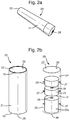
- a charge container 20 formed from a substantially rigid, combustible material, having a wall 21 which defines a cavity 24 where one or more cartridge cases 23 of energetic material may be inserted in a horizontal stacked formation and be coaxially aligned.
- a top portion 19 comprising an aperture 22 to allow the loading and unloading of one or more cartridge cases 23, and the expulsion of gases formed from the exothermic output from the energetic material.
- the charge container 20 has a base portion 18, which prevents cartridge cases 23 from passing through the charge container 20 and may also house an ignition means or comprise a second aperture 28 for the insertion of such a means.
- the first cartridge case is the fixed cartridge case 23a, which is preferably securely affixed, such that it is not removable from the charge container 20. This ensures that there is always a minimum amount of propellant to ensure any projectile is launched a minimum distance. Further the fixed cartridge case 23a in the container 20, may serve as a blank training round, thereby removing the need for a specialist training round.
- the further cartridge cases 23 are held within the cavity of the charge container 20, and may be reversibly linked to one another, by a reversible means 26.
- the charge container or cartridge cases may comprise spacers 27 attached to create a gap 25 between the wall interior 29 of the charge container 20 and each cartridge case 23.
- the gap 25 created by the use of the spacers 27 then allows the propagation of a flame front, formed by the explosive chain, to travel up the outside of the fixed 23a and further cartridge cases 23, to allow more uniform ignite all of the further cartridge cases 23, in a more uniform .
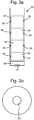
- FIG. 3a and 3b there is provided an example charge container 30 showing coaxially and horizontally stacked fixed cartridge case 39 and further cartridge cases 33.
- the charge container 30 comprises a number of spacers 36 to provide a gap between the cartridge cases 33 and the inner wall of the charge container 30 and the integral fixed cartridge case 39.
- the fixed cartridge case 39 provides a safety charge and minimum launch distance for the projectile to be launched.
- a base pad 34 is positioned below the fixed cartridge case 39 to initiate the explosive chain.
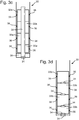
- Figures 3c and 3d show various combinations of the cartridge cases 33a and ignition means 34.
- Fig 3c shows the use of a central core igniter 38, running the length of the charge container 30.
- the cartridge case 33a is formed with a centrally located void to allow the insertion of the central core igniter 38.
- Fig 3d shows an alternative embodiment of the charge container 30 with no fixed cartridge case and with individual base pad igniters 34 integral to each cartridge case 33b. This allows a greater flexibility in cartridge case 33b use and cheaper construction of
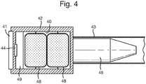
- a gun barrel chamber 42 there is provided a gun barrel chamber 42.
- the barrel Chamber volume is substantially filled by the charge container 40.
- the shell 45 sits typically within the rifled part of the barrel with only a small amount protruding into the barrel chamber.
- the charge container 40 substantially fills the cavity formed by the barrel chamber 42.
- the charge container 40 has a fixed cartridge container 49 attached towards the base of the charge container 40 in order to ensure the charge container 42 is capable in use of launching the shell 45 to a minimum launch distance.
- the charge container 42 further comprises a base pad ignitor 44 as its ignition source and two further cartridge containers 48.
- the base pad 44 is struck, which begins the ignition process, wherein the charge containers 48 are ignited and the resulting energy is expelled through the barrel 43 of the gun, forcing the shell 45, which substantially occupies the rifled barrel 42, out of the end of the barrel and towards its target.
Landscapes
- Engineering & Computer Science (AREA)
- General Engineering & Computer Science (AREA)
- Portable Nailing Machines And Staplers (AREA)
- Medicinal Preparation (AREA)
- Agricultural Chemicals And Associated Chemicals (AREA)
Claims (13)
- Dispositif de conteneur de charge (20), ledit dispositif de conteneur de charge ayant un volume adapté pour remplir sensiblement une chambre de barillet, ledit dispositif de conteneur de charge étant formé d'un matériau sensiblement rigide et combustible, dans lequel ledit dispositif de conteneur de charge comprend au moins une paroi (21) destinée à définir une cavité (24) pour la rétention d'au moins un logement de cartouche modulaire (23), ledit au moins un logement de cartouche modulaire comprenant un agent propulseur, dans lequel ledit au moins un logement de cartouche modulaire est prévu dans une formation empilée dans ledit dispositif de conteneur de charge, le dispositif de conteneur de charge comprenant en outre une partie de base (18) et une partie supérieure (19),
dans lequel la partie supérieure comprend une ouverture (28) destinée à permettre l'expulsion d'énergie et la partie de base comprend un moyen d'allumage, caractérisé en ce que le dispositif de conteneur de charge comprend un premier logement de cartouche fixe (23a) au niveau de sa partie de base afin de garantir que le conteneur de charge est capable, pendant son utilisation, de lancer un projectile sur une distance minimum, et un ou plusieurs autre (s) logement(s) de cartouche modulaire. - Dispositif selon l'une quelconque des revendications précédentes, dans lequel le ou les autre (s) logement (s) de cartouche modulaire est/sont fixé(s) de manière réversible sur la paroi du dispositif de conteneur de charge par des moyens de fixation (26).
- Dispositif selon la revendication 2, dans lequel les moyens de fixation sont un ensemble de crochets et de boucles réversible.
- Dispositif selon la revendication 2, dans lequel les moyens de fixation sont des entretoises (27) fixées sur le côté interne de la paroi du conteneur de charge.
- Dispositif selon l'une quelconque des revendications précédentes, dans lequel le conteneur de charge est fabriqué en mélange de nitrocellulose et de kraft.
- Dispositif selon l'une quelconque des revendications précédentes, dans lequel les logements de cartouche modulaire sont fabriqués en matériau flexible, comme du coton ou du polyester.
- Dispositif selon l'une quelconque des revendications précédentes, dans lequel un espace est formé entre les logements de cartouche modulaire et le côté interne de la paroi, afin de permettre la propagation d'un front de flamme.
- Dispositif selon l'une quelconque des revendications précédentes, dans lequel l'espace formé entre les logements de cartouche modulaire et le côté interne de la paroi est compris entre 1 mm et 10 mm.
- Dispositif selon l'une quelconque des revendications précédentes, dans lequel plusieurs logements de cartouche modulaire dans le conteneur de charge sont prévus en une pile horizontale.
- Dispositif selon l'une quelconque des revendications précédentes, dans lequel chaque logement de cartouche modulaire est fixé de manière réversible sur un logement de cartouche modulaire adjacent.
- Dispositif selon l'une quelconque des revendications précédentes, dans lequel le moyen d'allumage est un allumeur de plaque de pose, situé à la base du conteneur de charge.
- Dispositif selon l'une quelconque des revendications précédentes, dans lequel le moyen d'allumage est un allumeur de noyau central, situé au centre respectif de chaque logement de cartouche modulaire.
- Dispositif selon l'une quelconque des revendications précédentes, dans lequel le matériau énergétique dans le logement de cartouche modulaire est une pastille ou un granulé.
Applications Claiming Priority (2)
| Application Number | Priority Date | Filing Date | Title |
|---|---|---|---|
| GB1618624.9A GB2555618B (en) | 2016-11-04 | 2016-11-04 | Munition charge container |
| PCT/GB2017/053159 WO2018083439A1 (fr) | 2016-11-04 | 2017-10-19 | Contenant de charge de propulsion |
Publications (2)
| Publication Number | Publication Date |
|---|---|
| EP3535543A1 EP3535543A1 (fr) | 2019-09-11 |
| EP3535543B1 true EP3535543B1 (fr) | 2021-03-31 |
Family
ID=60182811
Family Applications (1)
| Application Number | Title | Priority Date | Filing Date |
|---|---|---|---|
| EP17790818.3A Active EP3535543B1 (fr) | 2016-11-04 | 2017-10-19 | Contenant de charge de propulsion |
Country Status (7)
| Country | Link |
|---|---|
| US (1) | US10837741B2 (fr) |
| EP (1) | EP3535543B1 (fr) |
| AU (1) | AU2017352844B2 (fr) |
| GB (1) | GB2555618B (fr) |
| IL (1) | IL266274B (fr) |
| WO (1) | WO2018083439A1 (fr) |
| ZA (1) | ZA201902761B (fr) |
Families Citing this family (4)
| Publication number | Priority date | Publication date | Assignee | Title |
|---|---|---|---|---|
| GB2555616B (en) * | 2016-11-04 | 2021-10-06 | Bae Systems Plc | Modular charge container |
| GB2555618B (en) | 2016-11-04 | 2021-12-29 | Bae Systems Plc | Munition charge container |
| US10107607B1 (en) * | 2017-04-04 | 2018-10-23 | The United States Of America As Represented By The Secretary Of The Army | Radio frequency igniter |
| GB2629632A (en) * | 2023-05-05 | 2024-11-06 | Bae Systems Plc | Modular charge system |
Family Cites Families (22)
| Publication number | Priority date | Publication date | Assignee | Title |
|---|---|---|---|---|
| FR803967A (fr) * | 1935-07-01 | 1936-10-13 | Nouvelle gargousse, nouvelle cartouche et nouveaux tubes pour utilisation | |
| US2419949A (en) * | 1944-02-07 | 1947-05-06 | Edwin J Hottinger | Device for securing a propellent charge to an artillery primer |
| US2432706A (en) * | 1944-02-07 | 1947-12-16 | Usa | Propellant retainer |
| DE1123953B (de) * | 1960-07-01 | 1962-02-15 | Dynamit Nobel Ag | Kartusche fuer rueckstossfreie Geschuetze |
| DE1243053B (de) * | 1965-05-08 | 1967-06-22 | Rheinmetall Gmbh | Teilladungskartusche |
| DE3334026A1 (de) | 1983-09-21 | 1985-04-04 | Rheinmetall GmbH, 4000 Düsseldorf | Treibladungshuelse |
| AU778762B1 (en) | 1986-01-09 | 2004-12-23 | Royal Ordnance Plc | A composite propellant charge |
| DE3927400A1 (de) * | 1989-08-19 | 1991-02-21 | Rheinmetall Gmbh | Verbrennbare treibladungshuelse |
| US5090323A (en) * | 1990-10-31 | 1992-02-25 | 501 Alliant Techsytems Inc. | Two-piece ammunition propellant containment bag |
| FR2672672B1 (fr) * | 1991-02-11 | 1993-04-16 | Giat Ind Sa | Conteneur pouvant recevoir une charge propulsive. |
| DE4124657A1 (de) | 1991-07-25 | 1993-01-28 | Rheinmetall Gmbh | Modulare treibladung |
| FR2684176B1 (fr) * | 1991-11-21 | 1995-04-28 | Giat Ind Sa | Fond de fermeture pour etui combustible. |
| US5263416A (en) | 1992-02-06 | 1993-11-23 | Alliant Techsystems Inc. | Primer propellant electrical ignition interconnect arrangement for single and multiple piece ammunition |
| DE4342428C2 (de) * | 1993-12-13 | 1999-05-27 | Rheinmetall W & M Gmbh | Geschützmunition mit einer verbrennbaren Treibladungshülse |
| JP3203573B2 (ja) | 1994-10-26 | 2001-08-27 | 防衛庁技術研究本部長 | 焼尽性容器 |
| SE519296C2 (sv) * | 1997-08-14 | 2003-02-11 | Bofors Defence Ab | Drivladdningsmodul |
| US6666141B2 (en) * | 2001-07-09 | 2003-12-23 | United Defense, L.P. | Variable increment modular artillery propellant |
| JP4520254B2 (ja) * | 2004-09-06 | 2010-08-04 | ダイセル化学工業株式会社 | 発射薬ユニット、及びこれを用いて形成された発射装薬 |
| US7726245B2 (en) * | 2008-04-25 | 2010-06-01 | Alliant Techsystems Inc. | Muzzleloader ammunition |
| KR20180055762A (ko) * | 2015-07-03 | 2018-05-25 | 니트로케미 비미스 아게 | 포탄용 추진 장약 시스템 |
| GB2555616B (en) | 2016-11-04 | 2021-10-06 | Bae Systems Plc | Modular charge container |
| GB2555618B (en) | 2016-11-04 | 2021-12-29 | Bae Systems Plc | Munition charge container |
-
2016
- 2016-11-04 GB GB1618624.9A patent/GB2555618B/en not_active Expired - Fee Related
-
2017
- 2017-10-19 IL IL266274A patent/IL266274B/en unknown
- 2017-10-19 AU AU2017352844A patent/AU2017352844B2/en active Active
- 2017-10-19 US US16/347,233 patent/US10837741B2/en active Active
- 2017-10-19 EP EP17790818.3A patent/EP3535543B1/fr active Active
- 2017-10-19 WO PCT/GB2017/053159 patent/WO2018083439A1/fr not_active Ceased
-
2019
- 2019-05-02 ZA ZA2019/02761A patent/ZA201902761B/en unknown
Also Published As
| Publication number | Publication date |
|---|---|
| US10837741B2 (en) | 2020-11-17 |
| GB2555618A (en) | 2018-05-09 |
| IL266274A (en) | 2019-06-30 |
| WO2018083439A1 (fr) | 2018-05-11 |
| EP3535543A1 (fr) | 2019-09-11 |
| ZA201902761B (en) | 2021-09-29 |
| US20190331467A1 (en) | 2019-10-31 |
| AU2017352844A1 (en) | 2019-05-16 |
| AU2017352844B2 (en) | 2022-09-22 |
| IL266274B (en) | 2022-07-01 |
| GB2555618B (en) | 2021-12-29 |
Similar Documents
| Publication | Publication Date | Title |
|---|---|---|
| EP3535543B1 (fr) | Contenant de charge de propulsion | |
| CA2663843C (fr) | Munition perfectionnee pour chargement par le canon | |
| US3398684A (en) | Caseless cartridges | |
| US11125541B2 (en) | Modular charge container | |
| RU2362960C2 (ru) | Патрон для нескольких метаемых тел | |
| EP1055096B1 (fr) | PROCEDE D'AMORçAGE DE CHARGES DE POUDRE PROPULSIVE D'ARTILLERIE, MODULE DE CHARGE DE POUDRE PROPULSIVE D'ARTILLERIE ET DE CHARGE DE POUDRE PROPULSIVE D'ARTILLERIE | |
| US12135197B2 (en) | Ammunition cartridge | |
| ZA200508435B (en) | Gun and method for assembling a gun | |
| US3421410A (en) | Missile and hand held launcher | |
| RU2192610C2 (ru) | Выстрел раздельного заряжания | |
| US9249759B1 (en) | Nozzled mortar ignition system for improved performance | |
| WO2024231656A1 (fr) | Système de charge modulaire | |
| US12276488B1 (en) | Multi-compartment mortar increment container | |
| CN102809326B (zh) | 一种可调膛压的无后坐力型爆炸物解体弹 | |
| ES2960306T3 (es) | Proyectil con detonador de fondo y carga de marcado | |
| JPS6247039Y2 (fr) | ||
| WO2005098348A8 (fr) | Munition encartouchee, notamment de calibre moyen | |
| PL200553B1 (pl) | Nabój ćwiczebny | |
| JPS6247040Y2 (fr) | ||
| RU2504729C2 (ru) | Способ и устройство поджига порохового заряда в огнестрельном оружии | |
| JPS6365300A (ja) | 迫撃砲弾用発射装薬包助燃装置 | |
| JPH04217799A (ja) | 発射装薬用点火薬 | |
| JPS6338897A (ja) | 演習用砲弾発射装置 | |
| PL142611B1 (en) | Grenade | |
| TW201809582A (zh) | 加速噴射子彈 |
Legal Events
| Date | Code | Title | Description |
|---|---|---|---|
| STAA | Information on the status of an ep patent application or granted ep patent |
Free format text: STATUS: UNKNOWN |
|
| STAA | Information on the status of an ep patent application or granted ep patent |
Free format text: STATUS: THE INTERNATIONAL PUBLICATION HAS BEEN MADE |
|
| PUAI | Public reference made under article 153(3) epc to a published international application that has entered the european phase |
Free format text: ORIGINAL CODE: 0009012 |
|
| STAA | Information on the status of an ep patent application or granted ep patent |
Free format text: STATUS: REQUEST FOR EXAMINATION WAS MADE |
|
| 17P | Request for examination filed |
Effective date: 20190507 |
|
| AK | Designated contracting states |
Kind code of ref document: A1 Designated state(s): AL AT BE BG CH CY CZ DE DK EE ES FI FR GB GR HR HU IE IS IT LI LT LU LV MC MK MT NL NO PL PT RO RS SE SI SK SM TR |
|
| AX | Request for extension of the european patent |
Extension state: BA ME |
|
| DAV | Request for validation of the european patent (deleted) | ||
| DAX | Request for extension of the european patent (deleted) | ||
| GRAP | Despatch of communication of intention to grant a patent |
Free format text: ORIGINAL CODE: EPIDOSNIGR1 |
|
| STAA | Information on the status of an ep patent application or granted ep patent |
Free format text: STATUS: GRANT OF PATENT IS INTENDED |
|
| INTG | Intention to grant announced |
Effective date: 20210115 |
|
| RIN1 | Information on inventor provided before grant (corrected) |
Inventor name: WILTON, ANNE MARIE |
|
| GRAS | Grant fee paid |
Free format text: ORIGINAL CODE: EPIDOSNIGR3 |
|
| GRAA | (expected) grant |
Free format text: ORIGINAL CODE: 0009210 |
|
| STAA | Information on the status of an ep patent application or granted ep patent |
Free format text: STATUS: THE PATENT HAS BEEN GRANTED |
|
| AK | Designated contracting states |
Kind code of ref document: B1 Designated state(s): AL AT BE BG CH CY CZ DE DK EE ES FI FR GB GR HR HU IE IS IT LI LT LU LV MC MK MT NL NO PL PT RO RS SE SI SK SM TR |
|
| REG | Reference to a national code |
Ref country code: GB Ref legal event code: FG4D Ref country code: CH Ref legal event code: EP |
|
| REG | Reference to a national code |
Ref country code: AT Ref legal event code: REF Ref document number: 1377405 Country of ref document: AT Kind code of ref document: T Effective date: 20210415 |
|
| REG | Reference to a national code |
Ref country code: DE Ref legal event code: R096 Ref document number: 602017035822 Country of ref document: DE |
|
| REG | Reference to a national code |
Ref country code: IE Ref legal event code: FG4D |
|
| REG | Reference to a national code |
Ref country code: EE Ref legal event code: FG4A Ref document number: E020766 Country of ref document: EE Effective date: 20210422 |
|
| REG | Reference to a national code |
Ref country code: LT Ref legal event code: MG9D |
|
| PG25 | Lapsed in a contracting state [announced via postgrant information from national office to epo] |
Ref country code: BG Free format text: LAPSE BECAUSE OF FAILURE TO SUBMIT A TRANSLATION OF THE DESCRIPTION OR TO PAY THE FEE WITHIN THE PRESCRIBED TIME-LIMIT Effective date: 20210630 Ref country code: NO Free format text: LAPSE BECAUSE OF FAILURE TO SUBMIT A TRANSLATION OF THE DESCRIPTION OR TO PAY THE FEE WITHIN THE PRESCRIBED TIME-LIMIT Effective date: 20210630 Ref country code: FI Free format text: LAPSE BECAUSE OF FAILURE TO SUBMIT A TRANSLATION OF THE DESCRIPTION OR TO PAY THE FEE WITHIN THE PRESCRIBED TIME-LIMIT Effective date: 20210331 Ref country code: HR Free format text: LAPSE BECAUSE OF FAILURE TO SUBMIT A TRANSLATION OF THE DESCRIPTION OR TO PAY THE FEE WITHIN THE PRESCRIBED TIME-LIMIT Effective date: 20210331 |
|
| PG25 | Lapsed in a contracting state [announced via postgrant information from national office to epo] |
Ref country code: RS Free format text: LAPSE BECAUSE OF FAILURE TO SUBMIT A TRANSLATION OF THE DESCRIPTION OR TO PAY THE FEE WITHIN THE PRESCRIBED TIME-LIMIT Effective date: 20210331 Ref country code: SE Free format text: LAPSE BECAUSE OF FAILURE TO SUBMIT A TRANSLATION OF THE DESCRIPTION OR TO PAY THE FEE WITHIN THE PRESCRIBED TIME-LIMIT Effective date: 20210331 |
|
| REG | Reference to a national code |
Ref country code: NL Ref legal event code: MP Effective date: 20210331 |
|
| REG | Reference to a national code |
Ref country code: AT Ref legal event code: MK05 Ref document number: 1377405 Country of ref document: AT Kind code of ref document: T Effective date: 20210331 |
|
| PG25 | Lapsed in a contracting state [announced via postgrant information from national office to epo] |
Ref country code: CZ Free format text: LAPSE BECAUSE OF FAILURE TO SUBMIT A TRANSLATION OF THE DESCRIPTION OR TO PAY THE FEE WITHIN THE PRESCRIBED TIME-LIMIT Effective date: 20210331 Ref country code: LT Free format text: LAPSE BECAUSE OF FAILURE TO SUBMIT A TRANSLATION OF THE DESCRIPTION OR TO PAY THE FEE WITHIN THE PRESCRIBED TIME-LIMIT Effective date: 20210331 Ref country code: AT Free format text: LAPSE BECAUSE OF FAILURE TO SUBMIT A TRANSLATION OF THE DESCRIPTION OR TO PAY THE FEE WITHIN THE PRESCRIBED TIME-LIMIT Effective date: 20210331 Ref country code: SM Free format text: LAPSE BECAUSE OF FAILURE TO SUBMIT A TRANSLATION OF THE DESCRIPTION OR TO PAY THE FEE WITHIN THE PRESCRIBED TIME-LIMIT Effective date: 20210331 Ref country code: NL Free format text: LAPSE BECAUSE OF FAILURE TO SUBMIT A TRANSLATION OF THE DESCRIPTION OR TO PAY THE FEE WITHIN THE PRESCRIBED TIME-LIMIT Effective date: 20210331 |
|
| PG25 | Lapsed in a contracting state [announced via postgrant information from national office to epo] |
Ref country code: IS Free format text: LAPSE BECAUSE OF FAILURE TO SUBMIT A TRANSLATION OF THE DESCRIPTION OR TO PAY THE FEE WITHIN THE PRESCRIBED TIME-LIMIT Effective date: 20210731 Ref country code: RO Free format text: LAPSE BECAUSE OF FAILURE TO SUBMIT A TRANSLATION OF THE DESCRIPTION OR TO PAY THE FEE WITHIN THE PRESCRIBED TIME-LIMIT Effective date: 20210331 Ref country code: SK Free format text: LAPSE BECAUSE OF FAILURE TO SUBMIT A TRANSLATION OF THE DESCRIPTION OR TO PAY THE FEE WITHIN THE PRESCRIBED TIME-LIMIT Effective date: 20210331 Ref country code: PT Free format text: LAPSE BECAUSE OF FAILURE TO SUBMIT A TRANSLATION OF THE DESCRIPTION OR TO PAY THE FEE WITHIN THE PRESCRIBED TIME-LIMIT Effective date: 20210802 Ref country code: PL Free format text: LAPSE BECAUSE OF FAILURE TO SUBMIT A TRANSLATION OF THE DESCRIPTION OR TO PAY THE FEE WITHIN THE PRESCRIBED TIME-LIMIT Effective date: 20210331 |
|
| REG | Reference to a national code |
Ref country code: DE Ref legal event code: R097 Ref document number: 602017035822 Country of ref document: DE |
|
| PG25 | Lapsed in a contracting state [announced via postgrant information from national office to epo] |
Ref country code: AL Free format text: LAPSE BECAUSE OF FAILURE TO SUBMIT A TRANSLATION OF THE DESCRIPTION OR TO PAY THE FEE WITHIN THE PRESCRIBED TIME-LIMIT Effective date: 20210331 Ref country code: DK Free format text: LAPSE BECAUSE OF FAILURE TO SUBMIT A TRANSLATION OF THE DESCRIPTION OR TO PAY THE FEE WITHIN THE PRESCRIBED TIME-LIMIT Effective date: 20210331 Ref country code: ES Free format text: LAPSE BECAUSE OF FAILURE TO SUBMIT A TRANSLATION OF THE DESCRIPTION OR TO PAY THE FEE WITHIN THE PRESCRIBED TIME-LIMIT Effective date: 20210331 |
|
| PLBE | No opposition filed within time limit |
Free format text: ORIGINAL CODE: 0009261 |
|
| STAA | Information on the status of an ep patent application or granted ep patent |
Free format text: STATUS: NO OPPOSITION FILED WITHIN TIME LIMIT |
|
| 26N | No opposition filed |
Effective date: 20220104 |
|
| REG | Reference to a national code |
Ref country code: CH Ref legal event code: PL |
|
| PG25 | Lapsed in a contracting state [announced via postgrant information from national office to epo] |
Ref country code: IS Free format text: LAPSE BECAUSE OF FAILURE TO SUBMIT A TRANSLATION OF THE DESCRIPTION OR TO PAY THE FEE WITHIN THE PRESCRIBED TIME-LIMIT Effective date: 20210731 |
|
| REG | Reference to a national code |
Ref country code: BE Ref legal event code: MM Effective date: 20211031 |
|
| PG25 | Lapsed in a contracting state [announced via postgrant information from national office to epo] |
Ref country code: MC Free format text: LAPSE BECAUSE OF FAILURE TO SUBMIT A TRANSLATION OF THE DESCRIPTION OR TO PAY THE FEE WITHIN THE PRESCRIBED TIME-LIMIT Effective date: 20210331 |
|
| PG25 | Lapsed in a contracting state [announced via postgrant information from national office to epo] |
Ref country code: LU Free format text: LAPSE BECAUSE OF NON-PAYMENT OF DUE FEES Effective date: 20211019 Ref country code: IT Free format text: LAPSE BECAUSE OF FAILURE TO SUBMIT A TRANSLATION OF THE DESCRIPTION OR TO PAY THE FEE WITHIN THE PRESCRIBED TIME-LIMIT Effective date: 20210331 Ref country code: BE Free format text: LAPSE BECAUSE OF NON-PAYMENT OF DUE FEES Effective date: 20211031 |
|
| PG25 | Lapsed in a contracting state [announced via postgrant information from national office to epo] |
Ref country code: LI Free format text: LAPSE BECAUSE OF NON-PAYMENT OF DUE FEES Effective date: 20211031 Ref country code: CH Free format text: LAPSE BECAUSE OF NON-PAYMENT OF DUE FEES Effective date: 20211031 |
|
| PG25 | Lapsed in a contracting state [announced via postgrant information from national office to epo] |
Ref country code: IE Free format text: LAPSE BECAUSE OF NON-PAYMENT OF DUE FEES Effective date: 20211019 |
|
| PG25 | Lapsed in a contracting state [announced via postgrant information from national office to epo] |
Ref country code: CY Free format text: LAPSE BECAUSE OF FAILURE TO SUBMIT A TRANSLATION OF THE DESCRIPTION OR TO PAY THE FEE WITHIN THE PRESCRIBED TIME-LIMIT Effective date: 20210331 |
|
| PG25 | Lapsed in a contracting state [announced via postgrant information from national office to epo] |
Ref country code: HU Free format text: LAPSE BECAUSE OF FAILURE TO SUBMIT A TRANSLATION OF THE DESCRIPTION OR TO PAY THE FEE WITHIN THE PRESCRIBED TIME-LIMIT; INVALID AB INITIO Effective date: 20171019 Ref country code: GR Free format text: LAPSE BECAUSE OF FAILURE TO SUBMIT A TRANSLATION OF THE DESCRIPTION OR TO PAY THE FEE WITHIN THE PRESCRIBED TIME-LIMIT Effective date: 20210331 |
|
| PG25 | Lapsed in a contracting state [announced via postgrant information from national office to epo] |
Ref country code: MK Free format text: LAPSE BECAUSE OF FAILURE TO SUBMIT A TRANSLATION OF THE DESCRIPTION OR TO PAY THE FEE WITHIN THE PRESCRIBED TIME-LIMIT Effective date: 20210331 |
|
| PG25 | Lapsed in a contracting state [announced via postgrant information from national office to epo] |
Ref country code: TR Free format text: LAPSE BECAUSE OF FAILURE TO SUBMIT A TRANSLATION OF THE DESCRIPTION OR TO PAY THE FEE WITHIN THE PRESCRIBED TIME-LIMIT Effective date: 20210331 |
|
| PG25 | Lapsed in a contracting state [announced via postgrant information from national office to epo] |
Ref country code: MT Free format text: LAPSE BECAUSE OF FAILURE TO SUBMIT A TRANSLATION OF THE DESCRIPTION OR TO PAY THE FEE WITHIN THE PRESCRIBED TIME-LIMIT Effective date: 20210331 |
|
| PGFP | Annual fee paid to national office [announced via postgrant information from national office to epo] |
Ref country code: GB Payment date: 20250923 Year of fee payment: 9 |
|
| PGFP | Annual fee paid to national office [announced via postgrant information from national office to epo] |
Ref country code: FR Payment date: 20250924 Year of fee payment: 9 |
|
| PGFP | Annual fee paid to national office [announced via postgrant information from national office to epo] |
Ref country code: EE Payment date: 20250927 Year of fee payment: 9 |
|
| PGFP | Annual fee paid to national office [announced via postgrant information from national office to epo] |
Ref country code: LV Payment date: 20250923 Year of fee payment: 9 |
|
| PGFP | Annual fee paid to national office [announced via postgrant information from national office to epo] |
Ref country code: DE Payment date: 20250923 Year of fee payment: 9 |