EP3535545B1 - Interferometrischer positionssensor - Google Patents
Interferometrischer positionssensor Download PDFInfo
- Publication number
- EP3535545B1 EP3535545B1 EP17795028.4A EP17795028A EP3535545B1 EP 3535545 B1 EP3535545 B1 EP 3535545B1 EP 17795028 A EP17795028 A EP 17795028A EP 3535545 B1 EP3535545 B1 EP 3535545B1
- Authority
- EP
- European Patent Office
- Prior art keywords
- sensor
- optical
- light
- interference pattern
- photodetectors
- Prior art date
- Legal status (The legal status is an assumption and is not a legal conclusion. Google has not performed a legal analysis and makes no representation as to the accuracy of the status listed.)
- Active
Links
Images

Classifications
-
- G—PHYSICS
- G01—MEASURING; TESTING
- G01B—MEASURING LENGTH, THICKNESS OR SIMILAR LINEAR DIMENSIONS; MEASURING ANGLES; MEASURING AREAS; MEASURING IRREGULARITIES OF SURFACES OR CONTOURS
- G01B9/00—Measuring instruments characterised by the use of optical techniques
- G01B9/02—Interferometers
- G01B9/02055—Reduction or prevention of errors; Testing; Calibration
- G01B9/02056—Passive reduction of errors
-
- G—PHYSICS
- G01—MEASURING; TESTING
- G01B—MEASURING LENGTH, THICKNESS OR SIMILAR LINEAR DIMENSIONS; MEASURING ANGLES; MEASURING AREAS; MEASURING IRREGULARITIES OF SURFACES OR CONTOURS
- G01B11/00—Measuring arrangements characterised by the use of optical techniques
- G01B11/26—Measuring arrangements characterised by the use of optical techniques for measuring angles or tapers; for testing the alignment of axes
-
- G—PHYSICS
- G01—MEASURING; TESTING
- G01B—MEASURING LENGTH, THICKNESS OR SIMILAR LINEAR DIMENSIONS; MEASURING ANGLES; MEASURING AREAS; MEASURING IRREGULARITIES OF SURFACES OR CONTOURS
- G01B9/00—Measuring instruments characterised by the use of optical techniques
- G01B9/02—Interferometers
- G01B9/02015—Interferometers characterised by the beam path configuration
- G01B9/02017—Interferometers characterised by the beam path configuration with multiple interactions between the target object and light beams, e.g. beam reflections occurring from different locations
- G01B9/02019—Interferometers characterised by the beam path configuration with multiple interactions between the target object and light beams, e.g. beam reflections occurring from different locations contacting different points on same face of object
-
- G—PHYSICS
- G01—MEASURING; TESTING
- G01B—MEASURING LENGTH, THICKNESS OR SIMILAR LINEAR DIMENSIONS; MEASURING ANGLES; MEASURING AREAS; MEASURING IRREGULARITIES OF SURFACES OR CONTOURS
- G01B9/00—Measuring instruments characterised by the use of optical techniques
- G01B9/02—Interferometers
- G01B9/02055—Reduction or prevention of errors; Testing; Calibration
- G01B9/02056—Passive reduction of errors
- G01B9/02061—Reduction or prevention of effects of tilts or misalignment
-
- G—PHYSICS
- G01—MEASURING; TESTING
- G01B—MEASURING LENGTH, THICKNESS OR SIMILAR LINEAR DIMENSIONS; MEASURING ANGLES; MEASURING AREAS; MEASURING IRREGULARITIES OF SURFACES OR CONTOURS
- G01B9/00—Measuring instruments characterised by the use of optical techniques
- G01B9/02—Interferometers
- G01B9/02055—Reduction or prevention of errors; Testing; Calibration
- G01B9/02075—Reduction or prevention of errors; Testing; Calibration of particular errors
- G01B9/02078—Caused by ambiguity
- G01B9/02079—Quadrature detection, i.e. detecting relatively phase-shifted signals
- G01B9/02081—Quadrature detection, i.e. detecting relatively phase-shifted signals simultaneous quadrature detection, e.g. by spatial phase shifting
-
- G—PHYSICS
- G01—MEASURING; TESTING
- G01D—MEASURING NOT SPECIALLY ADAPTED FOR A SPECIFIC VARIABLE; ARRANGEMENTS FOR MEASURING TWO OR MORE VARIABLES NOT COVERED IN A SINGLE OTHER SUBCLASS; TARIFF METERING APPARATUS; MEASURING OR TESTING NOT OTHERWISE PROVIDED FOR
- G01D5/00—Mechanical means for transferring the output of a sensing member; Means for converting the output of a sensing member to another variable where the form or nature of the sensing member does not constrain the means for converting; Transducers not specially adapted for a specific variable
- G01D5/26—Mechanical means for transferring the output of a sensing member; Means for converting the output of a sensing member to another variable where the form or nature of the sensing member does not constrain the means for converting; Transducers not specially adapted for a specific variable characterised by optical transfer means, i.e. using infrared, visible, or ultraviolet light
- G01D5/266—Mechanical means for transferring the output of a sensing member; Means for converting the output of a sensing member to another variable where the form or nature of the sensing member does not constrain the means for converting; Transducers not specially adapted for a specific variable characterised by optical transfer means, i.e. using infrared, visible, or ultraviolet light by interferometric means
-
- G—PHYSICS
- G01—MEASURING; TESTING
- G01B—MEASURING LENGTH, THICKNESS OR SIMILAR LINEAR DIMENSIONS; MEASURING ANGLES; MEASURING AREAS; MEASURING IRREGULARITIES OF SURFACES OR CONTOURS
- G01B2290/00—Aspects of interferometers not specifically covered by any group under G01B9/02
- G01B2290/15—Cat eye, i.e. reflection always parallel to incoming beam
-
- G—PHYSICS
- G01—MEASURING; TESTING
- G01B—MEASURING LENGTH, THICKNESS OR SIMILAR LINEAR DIMENSIONS; MEASURING ANGLES; MEASURING AREAS; MEASURING IRREGULARITIES OF SURFACES OR CONTOURS
- G01B2290/00—Aspects of interferometers not specifically covered by any group under G01B9/02
- G01B2290/45—Multiple detectors for detecting interferometer signals
Definitions
- This invention relates to an interferometric position sensor, and in particular, to a position sensor operable to sense the position of an object through measurements of an optical interference pattern.
- Interferometric position sensors are able to provide a high standard of precision and resolution. Typically such sensors function by separating two coherent beams of light and propagating them along two separate paths, one of which functions as a reference path and one of which functions as a measurement path. Differences in path length between reference and measurement paths results in an interference pattern when light propagating in the two paths is recombined, consisting for example of light and dark fringes where constructive and destructive interference takes place. Such sensors are therefore sensitive to movements at a scale similar to that of the wavelength of the light used.
- An example of such an interferometer is the well-known Michelson-Morley interferometer, which can be adapted for use as a position sensor.
- GB 2 296 766 A describes a laser interferometer with linear array of photodetector elements.
- an interferometric position sensor for sensing the position of an object, the position sensor comprising: a light source arranged to emit light; an optical element having a partially-reflective surface arranged to split the light between first and second optical paths, which first and second paths are configured such that the split light is recombined so as to form an optical interference pattern dependent on the difference between the optical path lengths of the first and second optical paths; and a detector array arranged to measure the intensity of at least a part of the optical interference pattern; wherein the optical element further comprises a reflective surface from which light propagating in the second optical path is reflected; and wherein at least one of the first and second optical path lengths is dependent on the position of the object such that changes in the optical interference pattern can be related to changes in the position of the object.
- Such a position sensor is able to provide enhanced precision to a number of applications.
- the sensor has enhanced stability, since two reflective components (the partially-reflective, beam-splitting surface and the reflective surface) in the reference path are formed from one optical element. As a result any movement or vibration to which the sensor is subjected will not affect the relative distance between these two reflective surfaces. Errors arising from changes in the distance between these two optical elements are therefore reduced.
- the position sensor is therefore better suited to operation in dynamic environments in which relative movement of the reflective surfaces may otherwise be possible.
- the optical interference pattern comprises a set of fringes which move in dependence on the movement of the object. Measurement of the movement of the optical interference pattern is then used to infer the change in position of the object as well as other characteristics of the motion of the object.
- the sensor is further configured to determine the velocity and acceleration of the platform. It will be understood that the sensor can be used either sensing linear motion or for sensing angular motion or tilt of an object, as is described in further detail below. In the latter case it will be appreciated that the position, velocity and acceleration sensed will be the orientation, angular velocity and angular acceleration of the object.
- the detector array comprises first and second photodetectors spaced apart at a distance of around an integer number of fringe widths of the optical interference pattern plus or minus a half fringe width.
- the detector array may comprise first and second photodetectors spaced apart at a distance not greater than the width of one fringe of the optical interference pattern on the detector array.
- the detector array may further comprise magnifying optics arranged to magnify the optical interference pattern at the detector array. The use of magnifying optics allows larger photodetectors to be used, since the fringe pattern being measured is larger.
- the position sensor is triggerable at an initial position of the object, and subsequently provide corrections to the initial position.
- the corrections to the initial position are determined by a digital counter in communication with one of the photodetectors so as to count the number of fringes passing said one of the photodetectors.
- a digital counter provides a convenient method by which the movement of the fringes can be counted.
- the direction of movement of the set of fringes can be determined by the initial state of the first and second photodetectors, and by which photodetector first records a change in its state.
- the object may be tiltable about an axis, and the position sensor may be configured such that the difference between optical path lengths of the first and second optical paths can be used to infer the tilt of the object about the axis.
- the first optical path may include a retroreflector mounted on the object.
- a retroreflector is particularly preferred in embodiments where the position sensor is used to measure tilt since, as an object tilts, the angle of incidence of the first light path on the object changes.
- a simple reflective surface would not reflect the light back along the same light path, and as a result the optical interference pattern may not be formed across a wide range of tilt of the object.
- the reflective surface may reflect light propagating from the partially reflective surface back to the partially reflecting surface so as to recombine with light propagating in the first optical path.
- the second light path is entirely contained within the optical element, as a result of which the arrangement is particularly stable to external movement.
- the second optical path may include a further retroreflector mounted on the object.
- This arrangement maintains some additional stability in the second optical path but increases the amount by which the optical path difference between the first and second light paths changes when the object tilts.
- the retroreflector and the further retroreflector may be mounted on the object substantially symmetrically about the axis. Adding weight to a particular part of the object can affect its balancing about the axis. A symmetric arrangement can have a reduced effect on any necessary re-balancing of the object.
- the detector array may be rotatable.
- the ability to rotate the detector array, for example by a few degrees, enables the detector array to be configured so as to receive a more appropriate projection of the optical interference pattern.
- the invention extends to a system comprising at least two interferometric position sensors as described above; the at least two interferometric position sensors being arranged to sense changes in the position of the object in mutually orthogonal directions.
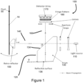
- Position sensor 100 is used for detecting the degree to which platform 10 is tilted about an axis running perpendicular to the plane of the diagram through pivot 50.
- Platform 10 may, for example, be a component part of an actuation mechanism used in precision additive layer manufacturing, and the position sensor 100 used to measure the degree to which the platform 10 has rotated.
- the position sensor 100 may assist in enabling the manufacture of parts with tolerances of the order of microns.
- the position sensor comprises a coherent light source 110, such as a laser diode; reference and measurement limbs 120 and 140 respectively; and a detector limb 160.
- the beam emitted by the light source 110 is broadened so as to provide a wavefront large enough to enable a suitable interference pattern to be created. Aperture stops are provided in order to minimise the propagation of stray light within the sensor.
- Optical element 130 is made from a standard material such as glass or fused silica, with standard optical coatings used to determine the partial reflectivity of the beam splitting surface 134. Further optical components (not shown) may be used to correct for any refraction effects at the beam-splitting surface 134.
- a glass wedge of appropriate geometry can be used or the element 130 can be embedded (or partially embedded) in a larger structure such that the beams propagate across interfaces between media of different refractive indices normally.
- the geometry of the optical element 130 it may be possible to select the geometry of the optical element 130 to tailor the beam paths appropriately.
- Element 130 is extended in the reference direction, terminating in a reflective surface 136 that reflects the light back towards the beam-splitting surface to propagate along the detector limb.
- the path of the light within the reference limb is therefore entirely contained within the optical element 130. This ensures consistent alignment of the components in the reference limb and a consistent path length for light propagating in the reference limb.
- the reflective surface 136 remains at a constant separation from the beam splitting surface 134, regardless of vibrations or other motion to which the interferometric positions sensor is subjected.
- the reflective surface 136 is angled such that the light is incident on it at an angle slightly off perpendicular.
- the measurement limb of the interferometer terminates at a retroreflector 150 mounted on the platform 10, shown as flat in Figure 1 for simplicity.
- the retroreflector in the present embodiment, is a corner-cube retroreflector which directs incident light back in the same direction from which it came. Thus light propagating along the measurement limb path is also reflected back towards the beam splitting surface 134 of the optical element 130.
- a retroreflector is used instead of a simple planar reflector because the tilting motion of the platform about pivot 50 results in the angle of the measurement limb relative to the interferometer changing as well as its length. A simple planar reflector would therefore not reflect light back to the beam-splitting surface 134 for all positions of the platform 10.
- the beam splitting surface 134 At the beam splitting surface 134, light from the measurement limb of the interferometer is also partially reflected towards the detector limb. Light from both the reference and measurement limbs therefore propagates along the detector limb towards a detector 170. Light from the reference limb interferes with that from the measurement limb to create a fringe pattern, indicated schematically at 180, in the detector limb. The pattern is magnified by suitable lenses and projected onto the detector 170. As is well understood, because the reflective surface 136 of the reference limb 120 is slightly off-perpendicular, the observed pattern will be of straight line fringes, with bright and dark fringes occurring at points dependent on the difference in optical path length between the reference and measurement limbs. As the length of the measurement limb 140 changes, therefore, the observed fringe pattern 180 will change.
- the length of the measurement limb 140 will of course change as the primary reflector, to which the retroreflector terminating the measurement limb is mounted, tilts about the axis. As the retroreflector moves, the observed fringes 180 will also appear to move, with the intensity recorded at any one point on the detector surface changing accordingly. Counting the number of fringes moving past a particular point on the detector can therefore be used to provide a measure of the amount by which the platform 10 has moved about the axis running through pivot 50.
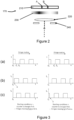
- the detector 170 is illustrated in further detail in Figure 2 and comprises a number of light sensors.
- two photodiodes A and 8, mounted on a platform 210, are provided to act as the detector.
- a detector optical element 220 is used to magnify the fringe pattern, firstly so that the photodiodes can be accommodated given the necessary separation, and secondly so that each photodiode is illuminated by one fringe at a time.
- the photodiodes are separated by a distance selected such that the phase difference between the light sensed by them is approximately one quarter wavelength. This arrangement can be seen in Figure 2 where fringes of the optical interference pattern (referenced with numeral 230), as magnified by the detector optical element 220, are shown in relative position to the photodiodes A and B.
- the platform 210 on which the photodiodes A and B are mounted is rotatable, so that the orientation of the photodiodes relative to the detector limb can be changed in order to achieve an improved profile of the optical interference pattern on the photodiodes.
- Each of the two photodetectors is connected to an digital counter which, because each of the photodetectors is illuminated by only one fringe at a time, is able to count the number of fringes that pass through counting the number of times that the photodiode switches from an illuminated 'on' state to an unilluminated 'off' state.
- Figure 3a schematically illustrates the optical intensity / of the fringe pattern varying with position x.
- the photodiodes are located at positions x A and x B , with x A ⁇ x B .
- Figures 3b and 3c schematically illustrate the optical intensity I A and I B as it varies with time t in two different starting conditions. For the purposes of illustration it is assumed that there is a step change in light intensity between the maximum and minimum intensities across one fringe in the optical interference pattern.
- the direction of movement of fringes can be deduced to be from the photodiode that changes first towards the photodiode that changes second; and that, where the photodiodes A and B start in different conditions (one on and the other off), then the direction of movement of fringes can be deduced to be to the photodiode that changes first from the photodiode that changes second.
- the counter can then count the number of transitions between the 'on' and 'off' states of the photodiodes in order to count the number of fringes that move past the photodiodes, and hence deduce the angle through which the primary reflector has moved.
- any changes in direction can be accounted for in a similar way using appropriate processing to record instances of the two photodiodes not transitioning between states in the appropriate order.
- the appropriate processing is performed by a suitably configured microprocessor chip in the digital counter.
- the angular precision of the interferometric position sensor 100 to changes in the orientation of the platform 10 about its pivot 50 can be estimated taking the assumption that the detector can identify the change in intensity from peak to minimum as a single fringe moves past the detector point as the smallest change in position of the retroreflector mounted on the platform 10.
- the change from peak to minimum occurs for a half-wavelength change in the distance along the measurement limb of the interferometric position sensor 100 as compared to the reference limb, the relevant wavelength ⁇ being that of the light emitted by light source 110.
- this distance would be 532 nm.
- the angular precision ⁇ can then be estimated from tan ⁇ ⁇ ⁇ /2 x , which, taking x to be of order 50 mm, results in ⁇ being approximately 0.01 mrad.
- the change in orientation of the platform between successive fringes calculated above can also be used to determine the orientation, angular velocity and angular acceleration of the platform 10, which quantities can be used in determining appropriate control for the platform 10.
- the digital counter includes a clock mechanism such that the counter's microprocessor can be configured to calculate the orientation, angular velocity and angular acceleration from the timing of the passing of the fringes, and provide these quantities as an output to the user or to a subsequent processor responsible, for example, for controlling the motion of the platform 10 or for using these quantities in further calculations.
- FIG. 4 is a schematic illustration of an alternative interferometric sensor 400 in accordance with a further embodiment of the invention.
- Sensor 400 provides a direct measurement of the tilt angle of a platform 440 as it is rotated about a pivot at a known point 90 about an axis perpendicular to the plane of the diagram, rather than a measurement of the linear displacement of a particular point on the platform from which a tilt angle must then be inferred.
- Interferometric sensor 400 includes a light source 410, the beam from which is split into two distinct paths by a partially reflecting surface 425 of a prism 420 before being recombined and brought to a focus so as to produce a pattern of interference fringes at a detector array 430.
- the paths terminate at one of two corner cube reflector elements 450 mounted on the platform 440.
- the two optical paths are each directed to a respective one of these elements 450 so as to be reflected back along their original path.
- the elements 450 are disposed symmetrically about the axis of rotation about which the tilt is to be measured.
- the length of both paths varies when the primary reflector tilts: one increasing in length, and the other decreasing in length by a corresponding amount.
- Light source 410 is, in the present embodiment, a laser, with appropriate beam broadening optics provided in order to generate an approximately planar wavefront large enough to ensure interference at the detector array 430.
- the broadened beam is normally incident on prism 420, through which it propagates to the partially reflective surface 425. At this surface the beam is split, a first part passing through the surface 425, and a second part being reflected through 90° through the prism towards a reflective surface 428 at the opposing end of the prism. This second part is reflected again through 90° at surface 428 so as to exit the prism in a direction parallel to the first part of the beam.
- Both first and second parts are incident on the corner cube retroreflectors mounted on the platform 440, so as to return to prism 420.
- Both first and second parts are reflected through 90° again by, respectively, the partially reflecting surface 425, and the reflective surface 428. In this way portions of the two parts are recombined and directed towards the detector array 430, having been brought to a focus by suitable optical components so as to generate a fringe pattern.
- the reflective surface 428 is slightly angled, about an axis defined by the intersection of the surface and the plane of the diagram. As shown in the Figure 4 , in the plane looking into the page, surface 428 is parallel to the partially reflective surface 425.
- the fringe pattern generated by interferometric sensor 400 will consist of a pattern of straight line fringes which will move as the platform 440 tilts, and the path length to each of the corner cube retroreflectors mounted on the platform changes. The number of fringes that pass any one particular point on the detector array can be directly related to the angle through which the platform 440 has moved.
- interferometric sensor 400 also removes alignment problems for the reflective surfaces 425 and 428 by making use of an extended prism component which ensures that the separation between the reflective surfaces remains constant despite external dynamic effects.
- platform 440 in interferometric sensor 400 is arranged so that its mass distribution is also symmetric about this axis.
- the interferometric position sensors 100, 400 are operable to sense movement in one direction. Where it is useful to sense movement of an object in more than one direction, or tilt of an object about more than one axis, a number of position sensors are used, arranged so as to sense changes in position in different directions. The different direction can be selected to be mutually orthogonal. For example, if a platform, such as platform 10, is mounted on a gimbal structure so as to be able to tilt about two axes, two position sensors 100 can be used, each one being operable to sense the degree of tilt about each axis. Similarly, more than one position sensor can be used in order to sense translational movement of an object in more than one direction.
- the spacing of the photodetectors in the above has been described to be approximately half the width of one of the fringes of the optical interference pattern, alternative separations of the photodetectors are possible. It will be immediately appreciated that, according to non-claimed embodiments, the determination of direction of fringe movement as described above can be performed in the same way if the photodetectors are at any separation less than one fringe width, although it is expected to work best when the separation is around one half fringe width. It may however be physically difficult to position the photodetectors this close to one another, depending on for example the strength of the magnifying optics that can be used.
- the photodetectors may in certain cases therefore be preferable for the photodetectors to be positioned further apart, and those skilled in the art will appreciate that the method described above for determining the direction of fringe movement will work similarly when the separation between the photodetectors is an integer number of fringe widths plus or minus a half fringe width.
Landscapes
- Physics & Mathematics (AREA)
- General Physics & Mathematics (AREA)
- Length Measuring Devices By Optical Means (AREA)
- Vehicle Body Suspensions (AREA)
- Ultra Sonic Daignosis Equipment (AREA)
- Measuring Fluid Pressure (AREA)
- Instruments For Measurement Of Length By Optical Means (AREA)
Claims (7)
- Interferometrischer Positionssensor (100, 400) zum Erfassen der Position eines Objekts, der Positionssensor umfassend:a) eine Lichtquelle (110, 410), die angeordnet ist, um Licht zu emittieren;b) ein optisches Element (130, 420), das eine teilweise reflektierende Oberfläche (134, 425) aufweist, die angeordnet ist, um das Licht zwischen einem ersten und einem zweiten optischen Weg (120, 140) aufzuspalten, wobei der erste und der zweite Weg derart konfiguriert sind, dass das aufgespaltene Licht rekombiniert wird, um ein optisches Interferenzmuster (180, 230) auszubilden, das von der Differenz zwischen den optischen Weglängen des ersten und des zweiten optischen Wegs abhängig ist; undc) eine Detektoranordnung (170, 430), die angeordnet ist, um die Intensität mindestens eines Teils des optischen Interferenzmusters zu messen, wobei die Detektoranordnung einen ersten und einen zweiten Fotodetektor (A, B) umfasst, die in einem Abstand beabstandet sind, der ungefähr gleich einer ganzzahligen Anzahl von Streifenbreiten plus einer halben Streifenbreite des optischen Interferenzmusters oder einer ganzzahligen Anzahl von Streifenbreiten minus einer halben Streifenbreite ist;wobei das optische Element ferner eine reflektierende Oberfläche (136, 428) umfasst, von der Licht, das sich in dem zweiten optischen Weg ausbreitet, reflektiert wird;wobei mindestens eine der ersten und der zweiten optischen Weglänge von der Position des Objekts derart abhängt, dass Änderungen in dem optischen Interferenzmuster auf Änderungen in der Position des Objekts bezogen werden können; wobei der Sensor ferner einen digitalen Zähler in Kommunikation mit einem der Fotodetektoren umfasst, wobei der digitale Zähler angeordnet ist, um die Anzahl von Streifen zu zählen, die den einen der Fotodetektoren passieren, und wobei der digitale Zähler an einer Anfangsposition des Objekts derart auslösbar ist, dass Korrekturen an der Anfangsposition in Abhängigkeit von der Ausgabe des digitalen Zählers bestimmt werden können;und wobei der Sensor konfiguriert ist, um die Geschwindigkeit und die Beschleunigung des Objekts zu bestimmen.
- Sensor nach Anspruch 1, wobei die Detektoranordnung einen ersten und einen zweiten Fotodetektor umfasst, die in einem Abstand voneinander beabstandet sind, der nicht größer als die Breite eines Streifens des optischen Interferenzmusters auf der Detektoranordnung ist.
- Sensor nach Anspruch 1 oder 2, ferner umfassend eine Vergrößerungsoptik, die angeordnet ist, um das optische Interferenzmuster an der Detektoranordnung zu vergrößern.
- Sensor nach einem der vorstehenden Ansprüche, der konfiguriert ist, um den Anfangszustand des ersten und des zweiten Fotodetektors zu bestimmen, wenn der digitale Zähler ausgelöst wird, wodurch die Bewegungsrichtung des Satzes von Streifen in Abhängigkeit davon bestimmt wird, welcher Fotodetektor zuerst eine Änderung seines Zustands aufzeichnet.
- Sensor nach einem der Ansprüche 1 bis 4, wobei die reflektierende Oberfläche Licht reflektiert, das sich von der teilweise reflektierenden Oberfläche zurück zu der teilweise reflektierenden Oberfläche ausbreitet, um mit Licht zu rekombinieren, das sich in dem ersten optischen Weg ausbreitet.
- Sensor nach einem der Ansprüche 1 bis 5, wobei die Detektoranordnung drehbar ist.
- System, umfassend mindestens zwei interferometrische Positionssensoren nach einem der Ansprüche 1 bis 6, wobei die mindestens zwei interferometrischen Positionssensoren angeordnet sind, um Änderungen der Position des Objekts in zueinander orthogonalen Richtungen zu erfassen.
Applications Claiming Priority (2)
| Application Number | Priority Date | Filing Date | Title |
|---|---|---|---|
| GB1618796.5A GB2555646A (en) | 2016-11-03 | 2016-11-03 | Interferometric position sensor |
| PCT/GB2017/053308 WO2018083482A1 (en) | 2016-11-03 | 2017-11-02 | Interferometric position sensor |
Publications (3)
| Publication Number | Publication Date |
|---|---|
| EP3535545A1 EP3535545A1 (de) | 2019-09-11 |
| EP3535545C0 EP3535545C0 (de) | 2023-08-02 |
| EP3535545B1 true EP3535545B1 (de) | 2023-08-02 |
Family
ID=60269855
Family Applications (1)
| Application Number | Title | Priority Date | Filing Date |
|---|---|---|---|
| EP17795028.4A Active EP3535545B1 (de) | 2016-11-03 | 2017-11-02 | Interferometrischer positionssensor |
Country Status (8)
| Country | Link |
|---|---|
| US (1) | US10928192B2 (de) |
| EP (1) | EP3535545B1 (de) |
| AU (1) | AU2017354910B2 (de) |
| ES (1) | ES2959246T3 (de) |
| GB (1) | GB2555646A (de) |
| IL (1) | IL266323B2 (de) |
| PL (1) | PL3535545T3 (de) |
| WO (1) | WO2018083482A1 (de) |
Families Citing this family (3)
| Publication number | Priority date | Publication date | Assignee | Title |
|---|---|---|---|---|
| US20220341725A1 (en) * | 2021-04-26 | 2022-10-27 | Quality Vision International Inc. | Non-invasive alignment method and system for imager-illuminator optical measurement machines |
| US12359977B1 (en) * | 2021-07-29 | 2025-07-15 | Lockheed Martin Corporation | Phase correction for optical interferometric imaging |
| CN115128800B (zh) * | 2022-06-27 | 2024-02-02 | 西北工业大学 | 基于f-p腔的光学位移敏感单元及逆设计方法 |
Family Cites Families (20)
| Publication number | Priority date | Publication date | Assignee | Title |
|---|---|---|---|---|
| US3145251A (en) * | 1959-10-07 | 1964-08-18 | Link Aviation Inc | Interferometers |
| US3409375A (en) * | 1964-10-21 | 1968-11-05 | Cutler Hammer Inc | Gauging interferometer systems |
| US3756722A (en) * | 1965-07-29 | 1973-09-04 | Kearney & Trecker Corp | Interferometric measuring system |
| US3443871A (en) * | 1965-12-07 | 1969-05-13 | Optomechanisms Inc | Single optical block interferometer means |
| US3734623A (en) * | 1972-03-01 | 1973-05-22 | Bendix Corp | Interferometer utilizing a tunable laser or similar frequency variable wave energy generator |
| US4566794A (en) * | 1981-04-22 | 1986-01-28 | Honeywell Inc. | Apparatus for interference fringe shift sensing |
| DE3419024A1 (de) | 1984-05-22 | 1985-09-26 | Daimler-Benz Ag, 7000 Stuttgart | Laserinterferometrisches winkelmessgeraet |
| DD234070A1 (de) * | 1985-01-18 | 1986-03-19 | Ilmenau Tech Hochschule | Interferometrische mehrkoordinatenmesseinrichtung |
| DE3623244A1 (de) | 1985-12-23 | 1987-06-25 | Suhl Feinmesszeugfab Veb | Beruehrungsloser interferometrischer sensor zur inkrementalen abtastung veraenderlicher interferenzstrukturen |
| GB8720014D0 (en) * | 1987-08-25 | 1987-09-30 | Renishaw Plc | Straightness interferometer |
| US4859066A (en) * | 1988-07-08 | 1989-08-22 | Zygo Corporation | Linear and angular displacement measuring interferometer |
| US5018862A (en) * | 1989-11-02 | 1991-05-28 | Aerotech, Inc. | Successive fringe detection position interferometry |
| GB9500110D0 (en) | 1995-01-05 | 1995-03-01 | Renishaw Plc | Laser interferometer |
| JP3441670B2 (ja) * | 1999-03-19 | 2003-09-02 | ペンタックス株式会社 | レンズ検査システム及びレンズ検査装置 |
| JP2001165616A (ja) * | 1999-12-10 | 2001-06-22 | Nec Corp | レーザ測長装置及びレーザ測長方法 |
| GB0025879D0 (en) * | 2000-10-23 | 2000-12-06 | Renishaw Plc | Interferometer |
| US20060017933A1 (en) * | 2004-07-23 | 2006-01-26 | Schluchter W C | Heterodyne laser interferometer with porro prisms for measuring stage displacement |
| US8174705B1 (en) | 2010-02-17 | 2012-05-08 | SA Photonics, Inc. | Tilting mirror controlled using null-based interferometric sensing |
| JP2012002616A (ja) * | 2010-06-16 | 2012-01-05 | Sigma Koki Co Ltd | 光学素子、及び干渉計 |
| CN103697807B (zh) | 2013-12-13 | 2016-04-13 | 清华大学 | 一种双频激光位移和角度干涉仪 |
-
2016
- 2016-11-03 GB GB1618796.5A patent/GB2555646A/en not_active Withdrawn
-
2017
- 2017-11-02 WO PCT/GB2017/053308 patent/WO2018083482A1/en not_active Ceased
- 2017-11-02 ES ES17795028T patent/ES2959246T3/es active Active
- 2017-11-02 PL PL17795028.4T patent/PL3535545T3/pl unknown
- 2017-11-02 AU AU2017354910A patent/AU2017354910B2/en active Active
- 2017-11-02 EP EP17795028.4A patent/EP3535545B1/de active Active
- 2017-11-02 US US16/346,581 patent/US10928192B2/en active Active
-
2019
- 2019-04-29 IL IL266323A patent/IL266323B2/en unknown
Also Published As
| Publication number | Publication date |
|---|---|
| GB2555646A (en) | 2018-05-09 |
| PL3535545T3 (pl) | 2024-01-29 |
| WO2018083482A1 (en) | 2018-05-11 |
| IL266323B2 (en) | 2023-05-01 |
| US20190257645A1 (en) | 2019-08-22 |
| EP3535545C0 (de) | 2023-08-02 |
| AU2017354910B2 (en) | 2022-07-07 |
| IL266323B1 (en) | 2023-01-01 |
| AU2017354910A1 (en) | 2019-05-23 |
| EP3535545A1 (de) | 2019-09-11 |
| CA3042340A1 (en) | 2018-05-11 |
| US10928192B2 (en) | 2021-02-23 |
| IL266323A (en) | 2019-06-30 |
| ES2959246T3 (es) | 2024-02-22 |
Similar Documents
| Publication | Publication Date | Title |
|---|---|---|
| EP2150770B1 (de) | Optischer distanzsensor | |
| NL1033095C2 (nl) | Littrow-interferometer. | |
| JPH07181007A (ja) | 干渉計応用測定装置 | |
| US9518816B2 (en) | Dual beam splitter interferometer measuring 3 degrees of freedom, system and method of use | |
| TWI452262B (zh) | 同時量測位移及傾角之干涉儀系統 | |
| EP3535545B1 (de) | Interferometrischer positionssensor | |
| JP5305732B2 (ja) | 干渉計 | |
| US9068811B2 (en) | Device for determining distance interferometrically | |
| JPH02266224A (ja) | 位置測定装置 | |
| JP6104708B2 (ja) | 追尾式レーザ干渉計 | |
| CN109708569B (zh) | 光学位置测量装置 | |
| Richter et al. | Position sensing and tracking with quasistatic MEMS mirrors | |
| CA3042340C (en) | Interferometric position sensor | |
| JP2011017582A (ja) | 光干渉計を用いた変位計測装置 | |
| JP3004631B1 (ja) | レーザー干渉計 | |
| CN119123970B (zh) | 一种紧凑型四光束干涉仪、制造方法及测量方法 | |
| WO1996031752A1 (en) | Apparatus for the measurement of angular displacement | |
| JPS6347603A (ja) | 光フアイバ変位センサ | |
| JP2025010643A (ja) | 干渉計 | |
| JPH0758174B2 (ja) | 平行度測定方法 | |
| JPH0376843B2 (de) | ||
| JPH02132310A (ja) | シアリング干渉計の補正方法 | |
| JPH06213619A (ja) | 干渉計 | |
| JPH01202637A (ja) | 光強度測定装置 | |
| JP2013003124A (ja) | 追尾式レーザ干渉計 |
Legal Events
| Date | Code | Title | Description |
|---|---|---|---|
| STAA | Information on the status of an ep patent application or granted ep patent |
Free format text: STATUS: UNKNOWN |
|
| STAA | Information on the status of an ep patent application or granted ep patent |
Free format text: STATUS: THE INTERNATIONAL PUBLICATION HAS BEEN MADE |
|
| PUAI | Public reference made under article 153(3) epc to a published international application that has entered the european phase |
Free format text: ORIGINAL CODE: 0009012 |
|
| STAA | Information on the status of an ep patent application or granted ep patent |
Free format text: STATUS: REQUEST FOR EXAMINATION WAS MADE |
|
| 17P | Request for examination filed |
Effective date: 20190501 |
|
| AK | Designated contracting states |
Kind code of ref document: A1 Designated state(s): AL AT BE BG CH CY CZ DE DK EE ES FI FR GB GR HR HU IE IS IT LI LT LU LV MC MK MT NL NO PL PT RO RS SE SI SK SM TR |
|
| AX | Request for extension of the european patent |
Extension state: BA ME |
|
| DAV | Request for validation of the european patent (deleted) | ||
| DAX | Request for extension of the european patent (deleted) | ||
| STAA | Information on the status of an ep patent application or granted ep patent |
Free format text: STATUS: EXAMINATION IS IN PROGRESS |
|
| 17Q | First examination report despatched |
Effective date: 20210629 |
|
| REG | Reference to a national code |
Ref country code: DE Ref legal event code: R079 Ref document number: 602017072188 Country of ref document: DE Free format text: PREVIOUS MAIN CLASS: G01B0009020000 Ipc: G01B0009020170 |
|
| GRAP | Despatch of communication of intention to grant a patent |
Free format text: ORIGINAL CODE: EPIDOSNIGR1 |
|
| STAA | Information on the status of an ep patent application or granted ep patent |
Free format text: STATUS: GRANT OF PATENT IS INTENDED |
|
| RIC1 | Information provided on ipc code assigned before grant |
Ipc: G01B 11/26 20060101ALI20221128BHEP Ipc: G01B 9/02055 20220101ALI20221128BHEP Ipc: G01B 9/02017 20220101AFI20221128BHEP |
|
| INTG | Intention to grant announced |
Effective date: 20221214 |
|
| GRAS | Grant fee paid |
Free format text: ORIGINAL CODE: EPIDOSNIGR3 |
|
| GRAA | (expected) grant |
Free format text: ORIGINAL CODE: 0009210 |
|
| STAA | Information on the status of an ep patent application or granted ep patent |
Free format text: STATUS: THE PATENT HAS BEEN GRANTED |
|
| AK | Designated contracting states |
Kind code of ref document: B1 Designated state(s): AL AT BE BG CH CY CZ DE DK EE ES FI FR GB GR HR HU IE IS IT LI LT LU LV MC MK MT NL NO PL PT RO RS SE SI SK SM TR |
|
| REG | Reference to a national code |
Ref country code: GB Ref legal event code: FG4D |
|
| REG | Reference to a national code |
Ref country code: CH Ref legal event code: EP |
|
| REG | Reference to a national code |
Ref country code: DE Ref legal event code: R096 Ref document number: 602017072188 Country of ref document: DE |
|
| REG | Reference to a national code |
Ref country code: IE Ref legal event code: FG4D |
|
| U01 | Request for unitary effect filed |
Effective date: 20230823 |
|
| U07 | Unitary effect registered |
Designated state(s): AT BE BG DE DK EE FI FR IT LT LU LV MT NL PT SE SI Effective date: 20230829 |
|
| U20 | Renewal fee for the european patent with unitary effect paid |
Year of fee payment: 7 Effective date: 20231019 |
|
| PG25 | Lapsed in a contracting state [announced via postgrant information from national office to epo] |
Ref country code: GR Free format text: LAPSE BECAUSE OF FAILURE TO SUBMIT A TRANSLATION OF THE DESCRIPTION OR TO PAY THE FEE WITHIN THE PRESCRIBED TIME-LIMIT Effective date: 20231103 |
|
| PG25 | Lapsed in a contracting state [announced via postgrant information from national office to epo] |
Ref country code: IS Free format text: LAPSE BECAUSE OF FAILURE TO SUBMIT A TRANSLATION OF THE DESCRIPTION OR TO PAY THE FEE WITHIN THE PRESCRIBED TIME-LIMIT Effective date: 20231202 |
|
| PG25 | Lapsed in a contracting state [announced via postgrant information from national office to epo] |
Ref country code: RS Free format text: LAPSE BECAUSE OF FAILURE TO SUBMIT A TRANSLATION OF THE DESCRIPTION OR TO PAY THE FEE WITHIN THE PRESCRIBED TIME-LIMIT Effective date: 20230802 Ref country code: NO Free format text: LAPSE BECAUSE OF FAILURE TO SUBMIT A TRANSLATION OF THE DESCRIPTION OR TO PAY THE FEE WITHIN THE PRESCRIBED TIME-LIMIT Effective date: 20231102 Ref country code: IS Free format text: LAPSE BECAUSE OF FAILURE TO SUBMIT A TRANSLATION OF THE DESCRIPTION OR TO PAY THE FEE WITHIN THE PRESCRIBED TIME-LIMIT Effective date: 20231202 Ref country code: HR Free format text: LAPSE BECAUSE OF FAILURE TO SUBMIT A TRANSLATION OF THE DESCRIPTION OR TO PAY THE FEE WITHIN THE PRESCRIBED TIME-LIMIT Effective date: 20230802 Ref country code: GR Free format text: LAPSE BECAUSE OF FAILURE TO SUBMIT A TRANSLATION OF THE DESCRIPTION OR TO PAY THE FEE WITHIN THE PRESCRIBED TIME-LIMIT Effective date: 20231103 |
|
| REG | Reference to a national code |
Ref country code: ES Ref legal event code: FG2A Ref document number: 2959246 Country of ref document: ES Kind code of ref document: T3 Effective date: 20240222 |
|
| PG25 | Lapsed in a contracting state [announced via postgrant information from national office to epo] |
Ref country code: SM Free format text: LAPSE BECAUSE OF FAILURE TO SUBMIT A TRANSLATION OF THE DESCRIPTION OR TO PAY THE FEE WITHIN THE PRESCRIBED TIME-LIMIT Effective date: 20230802 Ref country code: RO Free format text: LAPSE BECAUSE OF FAILURE TO SUBMIT A TRANSLATION OF THE DESCRIPTION OR TO PAY THE FEE WITHIN THE PRESCRIBED TIME-LIMIT Effective date: 20230802 Ref country code: CZ Free format text: LAPSE BECAUSE OF FAILURE TO SUBMIT A TRANSLATION OF THE DESCRIPTION OR TO PAY THE FEE WITHIN THE PRESCRIBED TIME-LIMIT Effective date: 20230802 Ref country code: SK Free format text: LAPSE BECAUSE OF FAILURE TO SUBMIT A TRANSLATION OF THE DESCRIPTION OR TO PAY THE FEE WITHIN THE PRESCRIBED TIME-LIMIT Effective date: 20230802 |
|
| REG | Reference to a national code |
Ref country code: DE Ref legal event code: R097 Ref document number: 602017072188 Country of ref document: DE |
|
| PLBE | No opposition filed within time limit |
Free format text: ORIGINAL CODE: 0009261 |
|
| STAA | Information on the status of an ep patent application or granted ep patent |
Free format text: STATUS: NO OPPOSITION FILED WITHIN TIME LIMIT |
|
| REG | Reference to a national code |
Ref country code: CH Ref legal event code: PL |
|
| PG25 | Lapsed in a contracting state [announced via postgrant information from national office to epo] |
Ref country code: MC Free format text: LAPSE BECAUSE OF FAILURE TO SUBMIT A TRANSLATION OF THE DESCRIPTION OR TO PAY THE FEE WITHIN THE PRESCRIBED TIME-LIMIT Effective date: 20230802 |
|
| 26N | No opposition filed |
Effective date: 20240503 |
|
| PG25 | Lapsed in a contracting state [announced via postgrant information from national office to epo] |
Ref country code: CH Free format text: LAPSE BECAUSE OF NON-PAYMENT OF DUE FEES Effective date: 20231130 |
|
| PG25 | Lapsed in a contracting state [announced via postgrant information from national office to epo] |
Ref country code: MC Free format text: LAPSE BECAUSE OF FAILURE TO SUBMIT A TRANSLATION OF THE DESCRIPTION OR TO PAY THE FEE WITHIN THE PRESCRIBED TIME-LIMIT Effective date: 20230802 Ref country code: CH Free format text: LAPSE BECAUSE OF NON-PAYMENT OF DUE FEES Effective date: 20231130 |
|
| REG | Reference to a national code |
Ref country code: IE Ref legal event code: MM4A |
|
| PG25 | Lapsed in a contracting state [announced via postgrant information from national office to epo] |
Ref country code: IE Free format text: LAPSE BECAUSE OF NON-PAYMENT OF DUE FEES Effective date: 20231102 |
|
| PG25 | Lapsed in a contracting state [announced via postgrant information from national office to epo] |
Ref country code: IE Free format text: LAPSE BECAUSE OF NON-PAYMENT OF DUE FEES Effective date: 20231102 |
|
| U20 | Renewal fee for the european patent with unitary effect paid |
Year of fee payment: 8 Effective date: 20241022 |
|
| PG25 | Lapsed in a contracting state [announced via postgrant information from national office to epo] |
Ref country code: CY Free format text: LAPSE BECAUSE OF FAILURE TO SUBMIT A TRANSLATION OF THE DESCRIPTION OR TO PAY THE FEE WITHIN THE PRESCRIBED TIME-LIMIT; INVALID AB INITIO Effective date: 20171102 |
|
| PG25 | Lapsed in a contracting state [announced via postgrant information from national office to epo] |
Ref country code: HU Free format text: LAPSE BECAUSE OF FAILURE TO SUBMIT A TRANSLATION OF THE DESCRIPTION OR TO PAY THE FEE WITHIN THE PRESCRIBED TIME-LIMIT; INVALID AB INITIO Effective date: 20171102 |
|
| U20 | Renewal fee for the european patent with unitary effect paid |
Year of fee payment: 9 Effective date: 20251022 |
|
| PG25 | Lapsed in a contracting state [announced via postgrant information from national office to epo] |
Ref country code: TR Free format text: LAPSE BECAUSE OF FAILURE TO SUBMIT A TRANSLATION OF THE DESCRIPTION OR TO PAY THE FEE WITHIN THE PRESCRIBED TIME-LIMIT Effective date: 20230802 |
|
| PGFP | Annual fee paid to national office [announced via postgrant information from national office to epo] |
Ref country code: GB Payment date: 20251023 Year of fee payment: 9 |
|
| PGFP | Annual fee paid to national office [announced via postgrant information from national office to epo] |
Ref country code: PL Payment date: 20251023 Year of fee payment: 9 |
|
| PGFP | Annual fee paid to national office [announced via postgrant information from national office to epo] |
Ref country code: ES Payment date: 20251201 Year of fee payment: 9 |