EP3535740B1 - Procédé et dispositif de commande et d'alimentation d'un générateur de fumée - Google Patents
Procédé et dispositif de commande et d'alimentation d'un générateur de fumée Download PDFInfo
- Publication number
- EP3535740B1 EP3535740B1 EP17791107.0A EP17791107A EP3535740B1 EP 3535740 B1 EP3535740 B1 EP 3535740B1 EP 17791107 A EP17791107 A EP 17791107A EP 3535740 B1 EP3535740 B1 EP 3535740B1
- Authority
- EP
- European Patent Office
- Prior art keywords
- unit
- canister
- smoke generating
- charging
- driver circuit
- Prior art date
- Legal status (The legal status is an assumption and is not a legal conclusion. Google has not performed a legal analysis and makes no representation as to the accuracy of the status listed.)
- Active
Links
Images


Classifications
-
- G—PHYSICS
- G08—SIGNALLING
- G08B—SIGNALLING SYSTEMS, e.g. PERSONAL CALLING SYSTEMS; ORDER TELEGRAPHS; ALARM SYSTEMS
- G08B15/00—Identifying, scaring or incapacitating burglars, thieves or intruders, e.g. by explosives
- G08B15/02—Identifying, scaring or incapacitating burglars, thieves or intruders, e.g. by explosives with smoke, gas, or coloured or odorous powder or liquid
-
- F—MECHANICAL ENGINEERING; LIGHTING; HEATING; WEAPONS; BLASTING
- F41—WEAPONS
- F41H—ARMOUR; ARMOURED TURRETS; ARMOURED OR ARMED VEHICLES; MEANS OF ATTACK OR DEFENCE, e.g. CAMOUFLAGE, IN GENERAL
- F41H9/00—Equipment for attack or defence by spreading flame, gas or smoke or leurres; Chemical warfare equipment
- F41H9/06—Apparatus for generating artificial fog or smoke screens
Definitions
- the invention relates to a method and a device for controlling and powering a smoke generator.
- a smoke generator is an electrically ignited device for producing a non-toxic opaque smoke.
- a specific application for smoke generators is the use as an active addition to alarm systems.
- alarm systems are commonly used in domestic houses, industrial premises, commercial premises and office premises as well as other premises and buildings to detect unauthorized intrusion such as burglary, damages and similar.
- the smoke generator normally is activated in connection with activation of other alarm functions, such as sound signals and a request for assistance that is sent to a remote monitoring station.
- An anti-intrusion security system in accordance with EP2778599 comprises fog-generating devices which impairs the sight of an intruder when activated.
- the devices for generating the fog comprise a heat exchanger for heating and vaporising the fluid with a resistor embedded on a body.
- an intruder detection system is activated, an appropriate signal is sent to an anti-intrusion security system that initiates delivery of fog.
- EP2719432 discloses a fog-generating device comprising a power source and a reservoir containing fog-generating liquid.
- An external surveillance system may send an alarm signal to the fog-generating device, upon which a switch is controlled in the fog-generating device which closes a circuit containing the ignition energy source (e.g. a capacitor or supercapacitor) and the ignition means, thereby igniting the reagent.
- Document DE60207349 describes another example of a smoke generation system.
- a device for controlling and powering a smoke generator said device comprising a power output connected to said smoke generator for activating thereof.
- the invention relates also to a method for controlling and powering the smoke generator. There is a special concern about the possibility of having an accidental activation of the smoke generator. Once the smoke generation is activated, the pyrotechnic nature of the product disables the possibility of stopping the smoke generation.
- the device is a peripheral comprising a safety circuit and the smoke generator.
- the smoke generator comprises a smoke generator component, referred to as a canister.
- the device will generate smoke in the premises after a burglary or danger situation is verified, for instance from a remote monitoring station.
- the new device can be integrated in presently available alarm systems as any other peripheral, communicating with at least one control unit, also referred to as a gateway, via a radio frequency, RF, interface.
- the device is designed to guarantee a reliable activation during the full life cycle of the device.
- the device in accordance with the invention will have a very quick and secure action. Emission of smoke starts within seconds of activation and will last at least one minute. The opacity of the smoke is very high.
- an alarm system is arranged in premises in the form of a building 10.
- the alarm system comprises at least one control unit 12 also referred to as a gateway that, for example, includes a processor and an alarm unit for providing an alarm signal when the alarm is set off.
- the alarm system comprises at least one and preferably a plurality of premises perimeter detectors 14, such as a first premises perimeter detector 14a and a second premises perimeter detector 14b.
- the premises perimeter detectors 14 are, for example, detectors sensitive to the presence or passage of persons and objects.
- presence detectors include motion detectors, such as IR-detectors
- passage detectors include magnetic sensors arranged at windows 16 and doors, such as an entrance door 18. Other detectors with similar properties can also be included.
- the alarm system further comprises at least one and preferably a plurality of premises interior detectors 20, such as a first premises interior detector 20a and a second premises interior detector 20b.
- the interior detectors may include IR-sensors.
- the control unit 12 is connected to the premises perimeter detectors 14, the premises interior detectors 20 and to input means 22, such as a keypad or similar, for arming and disarming the detectors 14, 20 to arm and disarm the alarm system.
- the control unit 12 is activated and controlled by the input means 22.
- the control unit 12 is provided with the input means 22.
- the input means 22 is a remote device, such as a wireless remote device.
- the input means 22 is arranged in the vicinity of the entrance door 18.
- the input means 22 is arranged in any suitable location or is a portable device, such as a cell phone.
- the detectors 14, 20 are, for example, provided with wireless communication means for communicating with the control unit 12.
- the control unit 12 is connected to an alarm receiving centre 24, such as a remote alarm receiving centre, either by wire, such as a telephone line as indicated in Fig. 1 with a dashed line, or by a wireless telecommunications system such as GSM or other radio frequency systems.
- the connection also can be through the internet 26.
- the control unit 12 is provided with communication means for communicating with the remote alarm receiving centre 24.
- the alarm receiving centre 24 is located within the premises or within the building 10.
- the remote alarm receiving centre 24 comprises a web server 28, a control and communications unit 30 and a database 32.
- the web server 28 is an interface for a user to set up and to monitor the alarm system of the building 10. Different settings and information regarding the alarm system and different users of the alarm system are stored in the database 32. Communication between the user, the alarm system and the remote alarm receiving centre 24 is processed through the control and communications unit 30.
- At least one premises interior detector 20 comprises or is connected to an image capturing means, such as a camera, video camera or any other type of image capturing means, wherein the image capturing means is activated when said detector 20 is triggered.
- an image capturing means such as a camera, video camera or any other type of image capturing means
- at least one premises interior detector 20 comprises an image capturing means, which image capturing means is activated by the triggering of the interior detector 20 connected to it, so that the image capturing means is switched on when the interior detector 20 detects an unauthorized intrusion.
- a smoke generator 36 capable of producing and distributing an opaque smoke after being initiated and activated by the alarm system, preferably through the control unit 12.
- the smoke generator 36 can be arranged on a wall by a wall attachment or be designed to be placed on a table or shelf. After being activated the smoke generator 36 will emit smoke that eventually will fill the premises in the building.
- the embodiment of the smoke generator 36 shown in Fig. 2 comprises a smoke generator component, referred to as a canister 38.
- the canister is a chemical pyrotechnic component which is available for instance from French company ALSETECH.
- the smoke generated is completely non-toxic and contains only very small amounts of CO and CO 2 .
- the smoke generator 36 is a stand-alone or self-contained unit where a battery or a set of batteries form a power supply unit 40. Communication between the smoke generator 36 and other peripheral units of the alarm system and specifically the control unit 12 is handled by a communication unit 42.
- the smoke generator 36 is controlled by a central unit 44, comprising a processor and memory units.
- the central unit 44 will communicate with the control unit 12 of the alarm system when an alarm situation occurs and activation of the smoke generator 36 is desired. Control signals from the central unit 44 are forwarded to a driver circuit 46 that is connected to the canister 38.
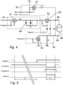
- An embodiment of the driver circuit 46 of the smoke generator 36 as shown in Fig. 3 comprises a charging unit 50, a switching unit 52 and a connecting unit 54.
- the charging unit 50 comprises charging means, such as capacitors or similar components capable of storing electric energy, and electronic circuits for controlling supply of current from the power supply unit 40 to the charging means, c.f. Fig. 4 .
- the charging unit 50 is connected to the central unit 44 and will receive a Charge signal when a smoke generator activating signal has been received by the central unit 44.
- the charging process of the charging means will take some time before an appropriate amount of energy has been obtained. In various embodiments a fixed time period is assigned for the charging process. In other embodiments the actual charged amount is measured by the central unit. No activation of the canister is possible during the charging process.
- a timing process for enabling and activating the smoke generator 36 is further explained below with reference to Fig. 5 .
- the canister 38 is connected to the connecting unit 54 which needs to enter a closing condition to allow the canister 38 to be activated properly.
- the closing condition is entered when a Connect signal is received from the driver circuit 46.
- the switching unit 52 is connected to the charging unit 50 and to the canister 38. In a final step for activating the canister 38 the switching unit 52 receives a trigger signal from the central unit 44. The switching unit 52 then switches on and energy stored in the charging unit 50 can be passed on to the canister 38 on the condition that the connecting unit 54 has entered the closing condition.
- the driver circuit 46 further comprises a testing unit 62 which is connected to the canister 38.
- the testing unit 62 has an input Test and an output Vtest. By applying a signal at input Test it is possible to detect presence of the canister 38 and also to detect information relating to the physical status of the canister 38. These data can be used to detect tampering attempts and when exchange of the canister is due.
- the charging unit 50 comprises a first active component 51.
- the first active component 51 is a P-channel enhancement mode MOSFET, such as one available from DIODES INCORPORATED as DMP2305U.
- the charging unit 50 further comprises charging means 60.
- a suitable implementation of the charging means 60 is at least one, or as shown in Fig. 4 two, capacitors with a total capacity of 6.600 ⁇ F.
- the charging unit 50 comprises a restricting resistor RD that will limit charging current from power supply VCC to the charging means 60.
- the switching unit 52 comprises in the shown embodiment a second active component 53.
- the second active component 53 is a P-channel trench MOSFET, such as one available from NXP SEMICONDUCTORS as PMV27UPE.
- PMV27UPE P-channel trench MOSFET
- An activation signal at input Trigger will connect a first pole 56 of the canister 38 to the charging means 60.
- Restricting resistor RD will limit current also in a situation where an activation signal at input Trigger is given in error during a time period where also a signal is provided at Charge input.
- the connecting unit 54 comprises in the shown embodiment a third active component 55.
- the third active component 55 is an N-channel trench MOSFET, such as one available from NXP SEMICONDUCTORS as PMV30UN2.
- NXP SEMICONDUCTORS as PMV30UN2.
- other suitable components can be used still providing the same function.
- a pre-activation signal at input Connect will connect a second pole 58 of the canister 38 to ground (GND).
- a current limiting resistor RL which is always connected between the second pole of the canister 38 and ground (GND) will limit the current through the canister below a level where the canister in is activated. In the shown embodiment RL is 3k Ohm.
- the testing unit 62 comprises a fourth active component 57.
- the fourth active component 57 is a P-channel enhancement mode MOSFET, such as one available from DIODES INCORPORATED as DMP2305U. In other arrangements, for instance with opposite polarities of power supply, other suitable components can be used still providing the same function.
- a test signal at the Test input fourth active component 57 will enter an ON state and current will be allowed to flow through a limiting resistor RT to the canister 38.
- the limiting resistor RT normally at about 3k Ohm, will ensure that the current to the canister 38 will be limited to a value below the value required for activation.
- the current to the canister will be limited to a maximum value of 1mA, even if the connecting unit 54 accidently is activated when the testing unit is activated.
- the current that actually flows through the canister when the test signal is applied will indicate presence of the canister 38 and also to some extent the status of content of the canister.
- a test output signal, Vtest can be obtained at the fourth active component 57.
- first pole 56 of canister 38 is connected to ground through shorting resistor RS and current limiting resistor RL.
- Second pole 58 of canister 38 is connected to ground through current limiting resistor RL.
- RS is 10k Ohm.
- Normal steps for activating the smoke generator to provide smoke include provision of input signal at input Charge.
- This input signal and also other signals indicated in Fig. 3 and Fig. 4 are provided by central unit 44 on the basis of signals received from the control unit 12 indicating an alarm situation.
- HIGH implies supply voltage VCC or a voltage level close to that.
- LOW implies ground GND or a voltage level close to that.
- An ON state of all active components corresponds to a closed switch condition, that is a condition where a maximum current flows through the component.
- An OFF state of all active components corresponds to an open switch condition, that is a condition where practically no current flows through the component.
- Signals at HIGH level are considered to be of opposite polarities as compared to signals at LOW level.
- the type of semiconductor used as first active component 51 is put into an ON state by changing from HIGH to a LOW signal at the gate of the P-channel enhancement mode MOSFET. As a result, current will flow from power supply at VCC and start charging the charging means 60.
- the time required for charging the charging means 60 to an appropriate level may vary in dependence on selected components and voltage levels. In the embodiment shown in Fig. 4 a normal charging time is about 500 ms. Even when charged to an appropriate level no energy is automatically transferred to the canister 38 because the second active component 53 is maintained at an OFF state in which current is prevented from passing through. Also third active component 55 is kept at an OFF state to further prevent activation of canister 38.
- First pole 56 of canister 38 is connected to "positive" units that will provide positive signals for activation of canister 38. These units are charging unit 50 and switching unit 52. Also the testing unit 62 is connected to first pole 56 of canister 38. Second pole 58 of canister 38 is connected to a "negative” unit that will provide a negative (or grounding) signal. Smoke generation requires that "positive” as well as “negative” units are activated during an overlapping time period. If “positive” charging unit 50 or “positive” switching unit 52 is activated while “negative” connecting unit 54 is not activated the maximum current that can flow through the canister 38 is limited by resistor RL. The limited current cannot activate smoke generation.
- Timing diagram of Fig. 5 shows how input signals CHARGE, TRIGGER and CONNECT interact to produce output FOG1 during normal conditions.
- the first step for activation of the smoke generator will be to activate input signal CHARGE by setting first active component 51 into ON state. This is done by applying a LOW signal. All other active components being in an OFF state current will flow through first active component 51 and through resistor RD to charging means 60.
- time period T1 in Fig. 5 is equal to about 500ms.
- input signal CHARGE is set to HIGH to set first active component 51 into OFF state. As a result, charging of charging means 60 is stopped.
- Activation of input signal TRIGGER is done by setting it to LOW.
- second active component 53 is set to ON which in practice connects first pole 56 of canister 38 to charging means 60 and will allow a current at a high level to flow into the canister 38.
- the high level current can be about 1A or more.
- smoke is generated during a time period T2.
- T2 is equal to or longer than 5 ms.
Landscapes
- Physics & Mathematics (AREA)
- General Physics & Mathematics (AREA)
- Engineering & Computer Science (AREA)
- General Engineering & Computer Science (AREA)
- Control Of Eletrric Generators (AREA)
- Alarm Systems (AREA)
- Fire Alarms (AREA)
- Fire-Detection Mechanisms (AREA)
Claims (8)
- Circuit d'attaque (46) de commande et d'alimentation d'une cartouche génératrice de fumée (38), ledit circuit d'attaque (46) comprenant une sortie d'alimentation connectée à ladite cartouche génératrice de fumée (38) pour l'activation de celle-ci,
ledit circuit d'attaque (46) comprenant
une unité de charge (50) fournissant après un processus de charge de l'alimentation suffisante pour allumer et attaquer ladite cartouche génératrice de fumée (38),
une unité de commutation (52) connectée à ladite unité de charge (50) et à un premier pôle (56) de ladite cartouche génératrice de fumée (38) pour libérer de l'alimentation de ladite unité de charge (50) vers ladite cartouche génératrice de fumée (38), et
une unité de connexion (54) connectée à un second pôle (58) de ladite cartouche génératrice de fumée (38) pour permettre à de l'alimentation de passer à travers ladite cartouche génératrice de fumée (38), l'activation de ladite unité de connexion (54) et de ladite unité de commutation (52) pendant une période de chevauchement étant nécessaire pour l'activation de ladite cartouche génératrice de fumée (38). - Circuit d'attaque (46) selon la revendication 1, dans lequel ladite unité de connexion (54) et ladite unité de commutation (52) sont activées par des signaux de polarités opposées.
- Circuit d'attaque (46) selon la revendication 1, dans lequel ladite unité de charge (50) comprend un premier composant actif (51), ladite unité de commutation (52) comprend un deuxième composant actif (53) et ladite unité de connexion (54) comprend un troisième composant actif (55), ledit premier composant actif (51), ledit deuxième composant actif (53) et ledit troisième composant actif (55) étant pourvus d'un état ON correspondant à une condition de commutation fermée et un état OFF correspondant à une condition de commutation ouverte.
- Circuit d'attaque (46) selon la revendication 3, dans lequel ladite unité de connexion (54) comprend une résistance de limitation de courant RL, connectée entre ledit second pôle (58) de ladite cartouche (38) et la masse (GND) afin de limiter du courant à travers ladite cartouche (38) lorsque le troisième composant actif (55) est à l'état OFF.
- Circuit d'attaque (46) selon la revendication 3 ou la revendication 4, dans lequel ladite unité de charge (50) comprend une résistance de restriction RD connectée entre ledit premier composant actif (51) et un moyen de charge (60) afin de limiter du courant passant dudit premier composant actif (51).
- Circuit d'attaque (46) selon la revendication 1, dans lequel une unité de test (62) est connectée à ladite cartouche (38) afin de fournir du courant limité destiné à traverser ladite cartouche (38) et dans lequel un passage de courant réel provenant de ladite unité de test (62) est déterminé afin d'indiquer que la cartouche (38) est connectée ou déconnectée.
- Procédé d'attaque de commande et d'alimentation d'une cartouche génératrice de fumée (38) pourvue d'un premier pôle (56) et d'un second pôle (58) pour recevoir et drainer, respectivement, du courant, et
appliquer un signal de charge au niveau d'une entrée de charge d'un circuit d'attaque (46) pour charger un moyen de charge (60) afin de stocker de l'énergie à l'intérieur de celui-ci, appliquer un signal de commande à une entrée de connexion dudit circuit d'attaque (46) afin de commuter une unité de connexion (54) vers un état ON dans lequel du courant est autorisé à passer de ladite cartouche génératrice de fumée (38) vers la masse (GND), et appliquer un signal de déclenchement au niveau d'une entrée de déclenchement de l'unité de commutation (52) vers un état ON dans lequel uniquement lorsque l'unité de connexion (54) et l'unité de commutation (52) sont dans un état ON pendant une période de chevauchement, le courant provenant dudit moyen de charge est transféré vers ladite cartouche génératrice de fumée (38), et de ladite cartouche génératrice de fumée (38) vers la masse (GND), et active ainsi la cartouche génératrice de fumée (38). - Générateur de fumée (36) comprenant une unité de communication (42), une unité centrale (44), un circuit d'attaque (46), une unité d'alimentation (40) et une cartouche génératrice de fumée (38), ladite unité de communication (42) étant agencée pour recevoir un signal d'activation de ladite cartouche génératrice de fumée (38), ladite unité centrale (44) étant agencée pour produire une pluralité de signaux de commande d'activation et de commande dudit circuit de commande (46), et ladite unité d'alimentation (40) étant agencée pour fournir en alimentation diverses unités du générateur de fumée (36), de manière à faire dudit générateur de fumée (36) une unité autonome,
ledit circuit d'attaque (46) comprenantune unité de charge (50) fournissant après un processus de charge de l'alimentation suffisante pour allumer et attaquer ladite cartouche génératrice de fumée (38),une unité de commutation (52) connectée à ladite unité de charge (50) et à un premier pôle (56) de ladite cartouche génératrice de fumée (38) pour libérer de l'alimentation de ladite unité de charge (50) vers ladite cartouche génératrice de fumée (38), etune unité de connexion (54) connectée à un second pôle (58) de ladite cartouche génératrice de fumée (38) pour permettre à de l'alimentation de passer à travers ladite cartouche génératrice de fumée (38), l'activation de ladite unité de connexion (54) et de ladite unité de commutation (52) pendant une période de chevauchement étant nécessaire pour l'activation de ladite cartouche génératrice de fumée (38).
Applications Claiming Priority (2)
| Application Number | Priority Date | Filing Date | Title |
|---|---|---|---|
| EP16197292.2A EP3319055B1 (fr) | 2016-11-04 | 2016-11-04 | Procédé et dispositif de commande et d'alimentation d'un générateur de fumée |
| PCT/EP2017/077901 WO2018083091A1 (fr) | 2016-11-04 | 2017-10-31 | Procédé et dispositif de commande et d'alimentation d'un générateur de fumée |
Publications (2)
| Publication Number | Publication Date |
|---|---|
| EP3535740A1 EP3535740A1 (fr) | 2019-09-11 |
| EP3535740B1 true EP3535740B1 (fr) | 2020-08-05 |
Family
ID=57348463
Family Applications (3)
| Application Number | Title | Priority Date | Filing Date |
|---|---|---|---|
| EP16197292.2A Active EP3319055B1 (fr) | 2016-11-04 | 2016-11-04 | Procédé et dispositif de commande et d'alimentation d'un générateur de fumée |
| EP25150505.3A Withdrawn EP4513460A3 (fr) | 2016-11-04 | 2016-11-04 | Procédé et dispositif de commande et d'alimentation d'un générateur de fumée |
| EP17791107.0A Active EP3535740B1 (fr) | 2016-11-04 | 2017-10-31 | Procédé et dispositif de commande et d'alimentation d'un générateur de fumée |
Family Applications Before (2)
| Application Number | Title | Priority Date | Filing Date |
|---|---|---|---|
| EP16197292.2A Active EP3319055B1 (fr) | 2016-11-04 | 2016-11-04 | Procédé et dispositif de commande et d'alimentation d'un générateur de fumée |
| EP25150505.3A Withdrawn EP4513460A3 (fr) | 2016-11-04 | 2016-11-04 | Procédé et dispositif de commande et d'alimentation d'un générateur de fumée |
Country Status (14)
| Country | Link |
|---|---|
| US (1) | US11098984B2 (fr) |
| EP (3) | EP3319055B1 (fr) |
| AU (1) | AU2017353293B2 (fr) |
| BR (1) | BR112019009056B1 (fr) |
| CA (1) | CA3042574A1 (fr) |
| CL (1) | CL2019001223A1 (fr) |
| CO (1) | CO2019004564A2 (fr) |
| ES (2) | ES3012968T3 (fr) |
| IL (1) | IL266396B (fr) |
| MX (1) | MX2019005210A (fr) |
| PE (1) | PE20191285A1 (fr) |
| PL (1) | PL3319055T3 (fr) |
| WO (1) | WO2018083091A1 (fr) |
| ZA (1) | ZA201902853B (fr) |
Families Citing this family (2)
| Publication number | Priority date | Publication date | Assignee | Title |
|---|---|---|---|---|
| PT3319056T (pt) | 2016-11-04 | 2020-04-08 | Verisure Sarl | Gerador de fumo com defletor |
| EP4207122A1 (fr) * | 2021-12-29 | 2023-07-05 | Verisure Sàrl | Localisation des intrus |
Family Cites Families (9)
| Publication number | Priority date | Publication date | Assignee | Title |
|---|---|---|---|---|
| ATE146002T1 (de) * | 1992-09-12 | 1996-12-15 | Paul Anton Dards | Einbrecher-abschrecksystem |
| CA2127804C (fr) * | 1992-11-26 | 1999-09-28 | Toshinori Sugimoto | Methode et dispositif anti-vol |
| EP0664532A1 (fr) * | 1994-01-21 | 1995-07-26 | Taher Burayez | Dispositif de sécurité pour véhicule automobile |
| GB9708447D0 (en) * | 1997-04-26 | 1997-06-18 | Gillrange Limited | Independent intruder detection and deterrent system |
| FR2829861B1 (fr) * | 2001-09-20 | 2003-11-21 | F V S | Procede interactif de mise en marche d'un appareil anti-intrusion, en particulier un fumigene, dispositif associe et systeme mettant en oeuvre ce procede |
| EP2026988A2 (fr) * | 2006-04-03 | 2009-02-25 | BluWav Systems, LLC | Propulsion de vehicule en forme d'un axe rattrapable avec un moteur, une batterie et une suspension |
| FR2977699B1 (fr) * | 2011-07-07 | 2015-01-09 | Oginski Herve Saiz | Procede de mise en marche en mode radio d'un generateur de fumee opacifiante anti-intrusion et dispositif mettant en œuvre un tel procede . |
| EP2719432A1 (fr) | 2012-10-11 | 2014-04-16 | Bandit NV | Dispositif de génération de brouillard et boîtier amovible associé |
| ITBS20130035A1 (it) | 2013-03-13 | 2014-09-14 | Mod Security S R L | Sistema di sicurezza antintrusione atto a generare una nebbia |
-
2016
- 2016-11-04 EP EP16197292.2A patent/EP3319055B1/fr active Active
- 2016-11-04 ES ES16197292T patent/ES3012968T3/es active Active
- 2016-11-04 PL PL16197292.2T patent/PL3319055T3/pl unknown
- 2016-11-04 EP EP25150505.3A patent/EP4513460A3/fr not_active Withdrawn
-
2017
- 2017-10-31 US US16/347,221 patent/US11098984B2/en active Active
- 2017-10-31 BR BR112019009056-8A patent/BR112019009056B1/pt active IP Right Grant
- 2017-10-31 AU AU2017353293A patent/AU2017353293B2/en active Active
- 2017-10-31 ES ES17791107T patent/ES2829334T3/es active Active
- 2017-10-31 PE PE2019000933A patent/PE20191285A1/es unknown
- 2017-10-31 EP EP17791107.0A patent/EP3535740B1/fr active Active
- 2017-10-31 MX MX2019005210A patent/MX2019005210A/es unknown
- 2017-10-31 WO PCT/EP2017/077901 patent/WO2018083091A1/fr not_active Ceased
- 2017-10-31 CA CA3042574A patent/CA3042574A1/fr active Pending
-
2019
- 2019-05-01 IL IL266396A patent/IL266396B/en unknown
- 2019-05-03 CL CL2019001223A patent/CL2019001223A1/es unknown
- 2019-05-03 CO CONC2019/0004564A patent/CO2019004564A2/es unknown
- 2019-05-07 ZA ZA2019/02853A patent/ZA201902853B/en unknown
Non-Patent Citations (1)
| Title |
|---|
| None * |
Also Published As
| Publication number | Publication date |
|---|---|
| EP4513460A2 (fr) | 2025-02-26 |
| MX2019005210A (es) | 2019-10-07 |
| BR112019009056B1 (pt) | 2023-11-14 |
| BR112019009056A2 (pt) | 2019-07-16 |
| EP4513460A3 (fr) | 2025-05-21 |
| EP3319055C0 (fr) | 2025-01-08 |
| PE20191285A1 (es) | 2019-09-20 |
| CO2019004564A2 (es) | 2019-09-18 |
| ES2829334T3 (es) | 2021-05-31 |
| US11098984B2 (en) | 2021-08-24 |
| ES3012968T3 (en) | 2025-04-10 |
| AU2017353293B2 (en) | 2021-11-25 |
| EP3319055A1 (fr) | 2018-05-09 |
| AU2017353293A1 (en) | 2019-05-23 |
| EP3319055B1 (fr) | 2025-01-08 |
| US20200333115A1 (en) | 2020-10-22 |
| IL266396A (en) | 2019-06-30 |
| PL3319055T3 (pl) | 2025-05-05 |
| IL266396B (en) | 2022-06-01 |
| CA3042574A1 (fr) | 2018-05-11 |
| CL2019001223A1 (es) | 2019-09-06 |
| ZA201902853B (en) | 2020-01-29 |
| WO2018083091A1 (fr) | 2018-05-11 |
| EP3535740A1 (fr) | 2019-09-11 |
Similar Documents
| Publication | Publication Date | Title |
|---|---|---|
| US5465094A (en) | Two terminal micropower radar sensor | |
| US4103294A (en) | Intruder deterrent apparatus and method | |
| US10713931B2 (en) | Portable alarm system | |
| US20130200855A1 (en) | System and Method for Discharging a Battery in a Vehicle after a Crash | |
| EP3535740B1 (fr) | Procédé et dispositif de commande et d'alimentation d'un générateur de fumée | |
| NZ560968A (en) | Electric fence system with modular components connected by wireless communication devices | |
| CN106785155B (zh) | 一种电池安全检测装置、电池模组及电动车 | |
| GB2384604A (en) | Remote property monitoring system using mobile phone text messaging | |
| US20180336777A1 (en) | System and method for automatically disarming an intrusion detection system | |
| KR20150029634A (ko) | 배터리를 작동 온도로 유지하기 위한 장치 및 방법 | |
| KR101777396B1 (ko) | 지능형 댁내 문 개폐 경보 장치 및 지능형 댁내 문 개폐 경보 시스템 | |
| US20250252845A1 (en) | Portable alarm system | |
| US4276545A (en) | Door activated burglar alarm utilizing time delay | |
| US20150042472A1 (en) | Non-battery powered wireless security system | |
| CN217543954U (zh) | 一种智能报警设备 | |
| ES2797775T3 (es) | Un sistema de protección antirrobo y antimanipulación | |
| Raghavendran | SMS based wireless home appliance control system | |
| CN110886571A (zh) | 一种智能安全门 | |
| CN209976366U (zh) | 一种智能安全门 | |
| CN107742396A (zh) | 一种智能安防控制装置 | |
| CN108870661A (zh) | 用于中央空调的智能调节系统 | |
| CN104077865A (zh) | 新型家用安防报警系统 | |
| KR200360299Y1 (ko) | 분사식 보안장치 | |
| WO2024248626A1 (fr) | Système de protection contre l'incendie | |
| CN104504832B (zh) | 电子看门装置 |
Legal Events
| Date | Code | Title | Description |
|---|---|---|---|
| STAA | Information on the status of an ep patent application or granted ep patent |
Free format text: STATUS: UNKNOWN |
|
| STAA | Information on the status of an ep patent application or granted ep patent |
Free format text: STATUS: THE INTERNATIONAL PUBLICATION HAS BEEN MADE |
|
| PUAI | Public reference made under article 153(3) epc to a published international application that has entered the european phase |
Free format text: ORIGINAL CODE: 0009012 |
|
| STAA | Information on the status of an ep patent application or granted ep patent |
Free format text: STATUS: REQUEST FOR EXAMINATION WAS MADE |
|
| 17P | Request for examination filed |
Effective date: 20190529 |
|
| AK | Designated contracting states |
Kind code of ref document: A1 Designated state(s): AL AT BE BG CH CY CZ DE DK EE ES FI FR GB GR HR HU IE IS IT LI LT LU LV MC MK MT NL NO PL PT RO RS SE SI SK SM TR |
|
| AX | Request for extension of the european patent |
Extension state: BA ME |
|
| DAV | Request for validation of the european patent (deleted) | ||
| DAX | Request for extension of the european patent (deleted) | ||
| GRAP | Despatch of communication of intention to grant a patent |
Free format text: ORIGINAL CODE: EPIDOSNIGR1 |
|
| STAA | Information on the status of an ep patent application or granted ep patent |
Free format text: STATUS: GRANT OF PATENT IS INTENDED |
|
| INTG | Intention to grant announced |
Effective date: 20200409 |
|
| GRAS | Grant fee paid |
Free format text: ORIGINAL CODE: EPIDOSNIGR3 |
|
| GRAA | (expected) grant |
Free format text: ORIGINAL CODE: 0009210 |
|
| STAA | Information on the status of an ep patent application or granted ep patent |
Free format text: STATUS: THE PATENT HAS BEEN GRANTED |
|
| AK | Designated contracting states |
Kind code of ref document: B1 Designated state(s): AL AT BE BG CH CY CZ DE DK EE ES FI FR GB GR HR HU IE IS IT LI LT LU LV MC MK MT NL NO PL PT RO RS SE SI SK SM TR |
|
| REG | Reference to a national code |
Ref country code: GB Ref legal event code: FG4D |
|
| REG | Reference to a national code |
Ref country code: CH Ref legal event code: EP |
|
| REG | Reference to a national code |
Ref country code: AT Ref legal event code: REF Ref document number: 1299790 Country of ref document: AT Kind code of ref document: T Effective date: 20200815 |
|
| REG | Reference to a national code |
Ref country code: DE Ref legal event code: R096 Ref document number: 602017021254 Country of ref document: DE |
|
| REG | Reference to a national code |
Ref country code: IE Ref legal event code: FG4D |
|
| REG | Reference to a national code |
Ref country code: CH Ref legal event code: NV Representative=s name: NOVAGRAAF INTERNATIONAL SA, CH |
|
| REG | Reference to a national code |
Ref country code: SE Ref legal event code: TRGR |
|
| REG | Reference to a national code |
Ref country code: LT Ref legal event code: MG4D |
|
| REG | Reference to a national code |
Ref country code: NO Ref legal event code: T2 Effective date: 20200805 |
|
| REG | Reference to a national code |
Ref country code: NL Ref legal event code: MP Effective date: 20200805 |
|
| REG | Reference to a national code |
Ref country code: AT Ref legal event code: MK05 Ref document number: 1299790 Country of ref document: AT Kind code of ref document: T Effective date: 20200805 |
|
| PG25 | Lapsed in a contracting state [announced via postgrant information from national office to epo] |
Ref country code: BG Free format text: LAPSE BECAUSE OF FAILURE TO SUBMIT A TRANSLATION OF THE DESCRIPTION OR TO PAY THE FEE WITHIN THE PRESCRIBED TIME-LIMIT Effective date: 20201105 Ref country code: GR Free format text: LAPSE BECAUSE OF FAILURE TO SUBMIT A TRANSLATION OF THE DESCRIPTION OR TO PAY THE FEE WITHIN THE PRESCRIBED TIME-LIMIT Effective date: 20201106 Ref country code: AT Free format text: LAPSE BECAUSE OF FAILURE TO SUBMIT A TRANSLATION OF THE DESCRIPTION OR TO PAY THE FEE WITHIN THE PRESCRIBED TIME-LIMIT Effective date: 20200805 Ref country code: FI Free format text: LAPSE BECAUSE OF FAILURE TO SUBMIT A TRANSLATION OF THE DESCRIPTION OR TO PAY THE FEE WITHIN THE PRESCRIBED TIME-LIMIT Effective date: 20200805 Ref country code: LT Free format text: LAPSE BECAUSE OF FAILURE TO SUBMIT A TRANSLATION OF THE DESCRIPTION OR TO PAY THE FEE WITHIN THE PRESCRIBED TIME-LIMIT Effective date: 20200805 Ref country code: PT Free format text: LAPSE BECAUSE OF FAILURE TO SUBMIT A TRANSLATION OF THE DESCRIPTION OR TO PAY THE FEE WITHIN THE PRESCRIBED TIME-LIMIT Effective date: 20201207 Ref country code: HR Free format text: LAPSE BECAUSE OF FAILURE TO SUBMIT A TRANSLATION OF THE DESCRIPTION OR TO PAY THE FEE WITHIN THE PRESCRIBED TIME-LIMIT Effective date: 20200805 |
|
| PG25 | Lapsed in a contracting state [announced via postgrant information from national office to epo] |
Ref country code: PL Free format text: LAPSE BECAUSE OF FAILURE TO SUBMIT A TRANSLATION OF THE DESCRIPTION OR TO PAY THE FEE WITHIN THE PRESCRIBED TIME-LIMIT Effective date: 20200805 Ref country code: LV Free format text: LAPSE BECAUSE OF FAILURE TO SUBMIT A TRANSLATION OF THE DESCRIPTION OR TO PAY THE FEE WITHIN THE PRESCRIBED TIME-LIMIT Effective date: 20200805 Ref country code: RS Free format text: LAPSE BECAUSE OF FAILURE TO SUBMIT A TRANSLATION OF THE DESCRIPTION OR TO PAY THE FEE WITHIN THE PRESCRIBED TIME-LIMIT Effective date: 20200805 Ref country code: NL Free format text: LAPSE BECAUSE OF FAILURE TO SUBMIT A TRANSLATION OF THE DESCRIPTION OR TO PAY THE FEE WITHIN THE PRESCRIBED TIME-LIMIT Effective date: 20200805 Ref country code: IS Free format text: LAPSE BECAUSE OF FAILURE TO SUBMIT A TRANSLATION OF THE DESCRIPTION OR TO PAY THE FEE WITHIN THE PRESCRIBED TIME-LIMIT Effective date: 20201205 |
|
| PG25 | Lapsed in a contracting state [announced via postgrant information from national office to epo] |
Ref country code: SM Free format text: LAPSE BECAUSE OF FAILURE TO SUBMIT A TRANSLATION OF THE DESCRIPTION OR TO PAY THE FEE WITHIN THE PRESCRIBED TIME-LIMIT Effective date: 20200805 Ref country code: EE Free format text: LAPSE BECAUSE OF FAILURE TO SUBMIT A TRANSLATION OF THE DESCRIPTION OR TO PAY THE FEE WITHIN THE PRESCRIBED TIME-LIMIT Effective date: 20200805 Ref country code: RO Free format text: LAPSE BECAUSE OF FAILURE TO SUBMIT A TRANSLATION OF THE DESCRIPTION OR TO PAY THE FEE WITHIN THE PRESCRIBED TIME-LIMIT Effective date: 20200805 Ref country code: DK Free format text: LAPSE BECAUSE OF FAILURE TO SUBMIT A TRANSLATION OF THE DESCRIPTION OR TO PAY THE FEE WITHIN THE PRESCRIBED TIME-LIMIT Effective date: 20200805 Ref country code: CZ Free format text: LAPSE BECAUSE OF FAILURE TO SUBMIT A TRANSLATION OF THE DESCRIPTION OR TO PAY THE FEE WITHIN THE PRESCRIBED TIME-LIMIT Effective date: 20200805 |
|
| REG | Reference to a national code |
Ref country code: DE Ref legal event code: R097 Ref document number: 602017021254 Country of ref document: DE |
|
| PG25 | Lapsed in a contracting state [announced via postgrant information from national office to epo] |
Ref country code: AL Free format text: LAPSE BECAUSE OF FAILURE TO SUBMIT A TRANSLATION OF THE DESCRIPTION OR TO PAY THE FEE WITHIN THE PRESCRIBED TIME-LIMIT Effective date: 20200805 |
|
| REG | Reference to a national code |
Ref country code: ES Ref legal event code: FG2A Ref document number: 2829334 Country of ref document: ES Kind code of ref document: T3 Effective date: 20210531 |
|
| PLBE | No opposition filed within time limit |
Free format text: ORIGINAL CODE: 0009261 |
|
| STAA | Information on the status of an ep patent application or granted ep patent |
Free format text: STATUS: NO OPPOSITION FILED WITHIN TIME LIMIT |
|
| PG25 | Lapsed in a contracting state [announced via postgrant information from national office to epo] |
Ref country code: LU Free format text: LAPSE BECAUSE OF NON-PAYMENT OF DUE FEES Effective date: 20201031 Ref country code: SK Free format text: LAPSE BECAUSE OF FAILURE TO SUBMIT A TRANSLATION OF THE DESCRIPTION OR TO PAY THE FEE WITHIN THE PRESCRIBED TIME-LIMIT Effective date: 20200805 Ref country code: MC Free format text: LAPSE BECAUSE OF FAILURE TO SUBMIT A TRANSLATION OF THE DESCRIPTION OR TO PAY THE FEE WITHIN THE PRESCRIBED TIME-LIMIT Effective date: 20200805 |
|
| 26N | No opposition filed |
Effective date: 20210507 |
|
| PG25 | Lapsed in a contracting state [announced via postgrant information from national office to epo] |
Ref country code: SI Free format text: LAPSE BECAUSE OF FAILURE TO SUBMIT A TRANSLATION OF THE DESCRIPTION OR TO PAY THE FEE WITHIN THE PRESCRIBED TIME-LIMIT Effective date: 20200805 |
|
| PG25 | Lapsed in a contracting state [announced via postgrant information from national office to epo] |
Ref country code: IE Free format text: LAPSE BECAUSE OF NON-PAYMENT OF DUE FEES Effective date: 20201031 |
|
| PG25 | Lapsed in a contracting state [announced via postgrant information from national office to epo] |
Ref country code: TR Free format text: LAPSE BECAUSE OF FAILURE TO SUBMIT A TRANSLATION OF THE DESCRIPTION OR TO PAY THE FEE WITHIN THE PRESCRIBED TIME-LIMIT Effective date: 20200805 Ref country code: MT Free format text: LAPSE BECAUSE OF FAILURE TO SUBMIT A TRANSLATION OF THE DESCRIPTION OR TO PAY THE FEE WITHIN THE PRESCRIBED TIME-LIMIT Effective date: 20200805 Ref country code: CY Free format text: LAPSE BECAUSE OF FAILURE TO SUBMIT A TRANSLATION OF THE DESCRIPTION OR TO PAY THE FEE WITHIN THE PRESCRIBED TIME-LIMIT Effective date: 20200805 |
|
| PG25 | Lapsed in a contracting state [announced via postgrant information from national office to epo] |
Ref country code: MK Free format text: LAPSE BECAUSE OF FAILURE TO SUBMIT A TRANSLATION OF THE DESCRIPTION OR TO PAY THE FEE WITHIN THE PRESCRIBED TIME-LIMIT Effective date: 20200805 |
|
| REG | Reference to a national code |
Ref country code: CH Ref legal event code: U11 Free format text: ST27 STATUS EVENT CODE: U-0-0-U10-U11 (AS PROVIDED BY THE NATIONAL OFFICE) Effective date: 20251101 |
|
| PGFP | Annual fee paid to national office [announced via postgrant information from national office to epo] |
Ref country code: DE Payment date: 20251029 Year of fee payment: 9 |
|
| PGFP | Annual fee paid to national office [announced via postgrant information from national office to epo] |
Ref country code: GB Payment date: 20251027 Year of fee payment: 9 |
|
| PGFP | Annual fee paid to national office [announced via postgrant information from national office to epo] |
Ref country code: NO Payment date: 20251029 Year of fee payment: 9 |
|
| PGFP | Annual fee paid to national office [announced via postgrant information from national office to epo] |
Ref country code: IT Payment date: 20251021 Year of fee payment: 9 |
|
| PGFP | Annual fee paid to national office [announced via postgrant information from national office to epo] |
Ref country code: FR Payment date: 20251027 Year of fee payment: 9 |
|
| PGFP | Annual fee paid to national office [announced via postgrant information from national office to epo] |
Ref country code: BE Payment date: 20251027 Year of fee payment: 9 |
|
| PGFP | Annual fee paid to national office [announced via postgrant information from national office to epo] |
Ref country code: SE Payment date: 20251027 Year of fee payment: 9 Ref country code: CH Payment date: 20251101 Year of fee payment: 9 |
|
| PGFP | Annual fee paid to national office [announced via postgrant information from national office to epo] |
Ref country code: ES Payment date: 20251103 Year of fee payment: 9 |