EP3535781B1 - Système de chargement de substrat - Google Patents
Système de chargement de substrat Download PDFInfo
- Publication number
- EP3535781B1 EP3535781B1 EP17868146.6A EP17868146A EP3535781B1 EP 3535781 B1 EP3535781 B1 EP 3535781B1 EP 17868146 A EP17868146 A EP 17868146A EP 3535781 B1 EP3535781 B1 EP 3535781B1
- Authority
- EP
- European Patent Office
- Prior art keywords
- tray
- substrate
- top surface
- aperture
- tabs
- Prior art date
- Legal status (The legal status is an assumption and is not a legal conclusion. Google has not performed a legal analysis and makes no representation as to the accuracy of the status listed.)
- Active
Links
Images





Classifications
-
- G—PHYSICS
- G03—PHOTOGRAPHY; CINEMATOGRAPHY; ANALOGOUS TECHNIQUES USING WAVES OTHER THAN OPTICAL WAVES; ELECTROGRAPHY; HOLOGRAPHY
- G03F—PHOTOMECHANICAL PRODUCTION OF TEXTURED OR PATTERNED SURFACES, e.g. FOR PRINTING, FOR PROCESSING OF SEMICONDUCTOR DEVICES; MATERIALS THEREFOR; ORIGINALS THEREFOR; APPARATUS SPECIALLY ADAPTED THEREFOR
- G03F7/00—Photomechanical, e.g. photolithographic, production of textured or patterned surfaces, e.g. printing surfaces; Materials therefor, e.g. comprising photoresists; Apparatus specially adapted therefor
- G03F7/70—Microphotolithographic exposure; Apparatus therefor
- G03F7/70691—Handling of masks or workpieces
- G03F7/70733—Handling masks and workpieces, e.g. exchange of workpiece or mask, transport of workpiece or mask
- G03F7/7075—Handling workpieces outside exposure position, e.g. SMIF box
-
- H—ELECTRICITY
- H10—SEMICONDUCTOR DEVICES; ELECTRIC SOLID-STATE DEVICES NOT OTHERWISE PROVIDED FOR
- H10P—GENERIC PROCESSES OR APPARATUS FOR THE MANUFACTURE OR TREATMENT OF DEVICES COVERED BY CLASS H10
- H10P72/00—Handling or holding of wafers, substrates or devices during manufacture or treatment thereof
- H10P72/30—Handling or holding of wafers, substrates or devices during manufacture or treatment thereof for conveying, e.g. between different workstations
- H10P72/36—Handling or holding of wafers, substrates or devices during manufacture or treatment thereof for conveying, e.g. between different workstations using air tracks
- H10P72/3604—Handling or holding of wafers, substrates or devices during manufacture or treatment thereof for conveying, e.g. between different workstations using air tracks the workpieces being stored in a carrier, involving loading and unloading
-
- G—PHYSICS
- G03—PHOTOGRAPHY; CINEMATOGRAPHY; ANALOGOUS TECHNIQUES USING WAVES OTHER THAN OPTICAL WAVES; ELECTROGRAPHY; HOLOGRAPHY
- G03F—PHOTOMECHANICAL PRODUCTION OF TEXTURED OR PATTERNED SURFACES, e.g. FOR PRINTING, FOR PROCESSING OF SEMICONDUCTOR DEVICES; MATERIALS THEREFOR; ORIGINALS THEREFOR; APPARATUS SPECIALLY ADAPTED THEREFOR
- G03F7/00—Photomechanical, e.g. photolithographic, production of textured or patterned surfaces, e.g. printing surfaces; Materials therefor, e.g. comprising photoresists; Apparatus specially adapted therefor
- G03F7/0002—Lithographic processes using patterning methods other than those involving the exposure to radiation, e.g. by stamping
-
- H—ELECTRICITY
- H10—SEMICONDUCTOR DEVICES; ELECTRIC SOLID-STATE DEVICES NOT OTHERWISE PROVIDED FOR
- H10P—GENERIC PROCESSES OR APPARATUS FOR THE MANUFACTURE OR TREATMENT OF DEVICES COVERED BY CLASS H10
- H10P72/00—Handling or holding of wafers, substrates or devices during manufacture or treatment thereof
- H10P72/04—Apparatus for manufacture or treatment
- H10P72/0451—Apparatus for manufacturing or treating in a plurality of work-stations
- H10P72/0462—Apparatus for manufacturing or treating in a plurality of work-stations characterised by the construction of the processing chambers, e.g. modular processing chambers
-
- H—ELECTRICITY
- H10—SEMICONDUCTOR DEVICES; ELECTRIC SOLID-STATE DEVICES NOT OTHERWISE PROVIDED FOR
- H10P—GENERIC PROCESSES OR APPARATUS FOR THE MANUFACTURE OR TREATMENT OF DEVICES COVERED BY CLASS H10
- H10P72/00—Handling or holding of wafers, substrates or devices during manufacture or treatment thereof
- H10P72/10—Handling or holding of wafers, substrates or devices during manufacture or treatment thereof using carriers specially adapted therefor, e.g. front opening unified pods [FOUP]
- H10P72/18—Handling or holding of wafers, substrates or devices during manufacture or treatment thereof using carriers specially adapted therefor, e.g. front opening unified pods [FOUP] characterised by being specially adapted for supporting a single substrate or by comprising a stack of such individual supports
-
- H—ELECTRICITY
- H10—SEMICONDUCTOR DEVICES; ELECTRIC SOLID-STATE DEVICES NOT OTHERWISE PROVIDED FOR
- H10P—GENERIC PROCESSES OR APPARATUS FOR THE MANUFACTURE OR TREATMENT OF DEVICES COVERED BY CLASS H10
- H10P72/00—Handling or holding of wafers, substrates or devices during manufacture or treatment thereof
- H10P72/30—Handling or holding of wafers, substrates or devices during manufacture or treatment thereof for conveying, e.g. between different workstations
- H10P72/33—Handling or holding of wafers, substrates or devices during manufacture or treatment thereof for conveying, e.g. between different workstations into and out of processing chamber
- H10P72/3311—Horizontal transfer of a batch of workpieces
-
- H—ELECTRICITY
- H10—SEMICONDUCTOR DEVICES; ELECTRIC SOLID-STATE DEVICES NOT OTHERWISE PROVIDED FOR
- H10P—GENERIC PROCESSES OR APPARATUS FOR THE MANUFACTURE OR TREATMENT OF DEVICES COVERED BY CLASS H10
- H10P72/00—Handling or holding of wafers, substrates or devices during manufacture or treatment thereof
- H10P72/30—Handling or holding of wafers, substrates or devices during manufacture or treatment thereof for conveying, e.g. between different workstations
- H10P72/34—Handling or holding of wafers, substrates or devices during manufacture or treatment thereof for conveying, e.g. between different workstations the wafers being stored in a carrier, involving loading and unloading
- H10P72/3411—Handling or holding of wafers, substrates or devices during manufacture or treatment thereof for conveying, e.g. between different workstations the wafers being stored in a carrier, involving loading and unloading involving loading and unloading of wafers
-
- H—ELECTRICITY
- H10—SEMICONDUCTOR DEVICES; ELECTRIC SOLID-STATE DEVICES NOT OTHERWISE PROVIDED FOR
- H10P—GENERIC PROCESSES OR APPARATUS FOR THE MANUFACTURE OR TREATMENT OF DEVICES COVERED BY CLASS H10
- H10P72/00—Handling or holding of wafers, substrates or devices during manufacture or treatment thereof
- H10P72/70—Handling or holding of wafers, substrates or devices during manufacture or treatment thereof for supporting or gripping
- H10P72/76—Handling or holding of wafers, substrates or devices during manufacture or treatment thereof for supporting or gripping using mechanical means, e.g. clamps or pinches
- H10P72/7604—Handling or holding of wafers, substrates or devices during manufacture or treatment thereof for supporting or gripping using mechanical means, e.g. clamps or pinches the wafers being placed on a susceptor, stage or support
- H10P72/7621—Handling or holding of wafers, substrates or devices during manufacture or treatment thereof for supporting or gripping using mechanical means, e.g. clamps or pinches the wafers being placed on a susceptor, stage or support characterised by supporting two or more semiconductor substrates
-
- H—ELECTRICITY
- H10—SEMICONDUCTOR DEVICES; ELECTRIC SOLID-STATE DEVICES NOT OTHERWISE PROVIDED FOR
- H10P—GENERIC PROCESSES OR APPARATUS FOR THE MANUFACTURE OR TREATMENT OF DEVICES COVERED BY CLASS H10
- H10P72/00—Handling or holding of wafers, substrates or devices during manufacture or treatment thereof
- H10P72/70—Handling or holding of wafers, substrates or devices during manufacture or treatment thereof for supporting or gripping
- H10P72/76—Handling or holding of wafers, substrates or devices during manufacture or treatment thereof for supporting or gripping using mechanical means, e.g. clamps or pinches
- H10P72/7604—Handling or holding of wafers, substrates or devices during manufacture or treatment thereof for supporting or gripping using mechanical means, e.g. clamps or pinches the wafers being placed on a susceptor, stage or support
- H10P72/7624—Handling or holding of wafers, substrates or devices during manufacture or treatment thereof for supporting or gripping using mechanical means, e.g. clamps or pinches the wafers being placed on a susceptor, stage or support characterised by the mechanical construction of the susceptor, stage or support
Definitions
- This invention relates to the loading of substrates, such as semiconductor wafers, in systems and methods involving microlithography and similar nano-fabrication techniques.
- Nano-fabrication includes the fabrication of very small structures that have features on the order of 100 nanometers or smaller.
- One application in which nano-fabrication has had a sizeable impact is in the processing of integrated circuits.
- the semiconductor processing industry continues to strive for larger production yields while increasing the circuits per unit area formed on a substrate, therefore nano-fabrication becomes increasingly important.
- Nano-fabrication provides greater process control while allowing continued reduction of the minimum feature dimensions of the structures formed.
- Other areas of development in which nano-fabrication has been employed include biotechnology, optical technology, mechanical systems, and the like.
- a prior art imprint lithography substrate transfer method is for instance described in WO 2007/084774 A2 .
- a tray handler device including a first tray handler positioned opposite a second tray handler; providing a first tray and a second tray, each of the first and the second trays defining an aperture and each having a top surface, each aperture defining at least two cutouts and two tabs; providing a substrate chuck having a top surface and a bottom surface; engaging the first tray handler with the first tray; positioning the tray handler device in a first position with i) the cutouts of the aperture of the first tray in superimposition with respective pedestals of a pedestal platform and ii) a distal end of the pedestals extending away from the top surface of the first tray; increasing a distance between the top surface of the first tray and a top surface of the pedestal platform to transfer a first substrate from the pedestals to the tabs defined by the aperture of the first tray, while concurrently engaging the second tray handler with the second tray; increasing a distance between the top surface of the second
- engaging the first tray handler with the first tray while concurrently increasing the distance between the top surface of the second tray and the top surface of the pedestal platform to transfer the third substrate from the pedestals to the tabs defined by the aperture of the second tray.
- the second substrate includes a patterned layer positioned thereon prior to transfer ring the second substrate from the substrate chuck to the tabs defined by the second tray.
- a tray handler device including a first tray handler positioned opposite a second tray handler, the first tray handler engageable with the first tray and the second tray handler engageable with the second tray, the tray hander rotatable between first and second positions, the first position having i) the cutouts of the aperture of the first tray in superimposition with respective pedestals of a pedestal platform and ii) a distal end of the pedestals extending away from the top surface of the first tray, the second position having i) the tabs defined by the aperture of the first tray in superimposition with respective channels of the substrate chuck and ii) the cutouts of the
- the system comprising a rotational system to rotate the tray handler device between the first and the second positions.
- the system comprising a patterning system to form a pattern in the first substrate when the first substrate is positioned on the top surface of the substrate chuck.
- the actuator system comprising a first actuator module, the first actuator module, when the tray handler device is in the first position, increase the distance between the top surface of the first tray and a top surface of the pedestal platform to transfer a first substrate from the pedestals to the tabs defined by the aperture of the first tray, while concurrently engaging the second tray handler with the second tray, and when the tray handler device is in the second position, decrease the distance between the top surface of the first tray and the bottom surface of the substrate chuck to transfer the first substrate from the tabs defined by the aperture of the first tray to the top surface of the substrate chuck while the tabs defined by the aperture of the first tray are disposed within the respective channels of the substrate chuck.
- the actuator system comprising a second actuator module, the second actuator module, when the tray handler is in the first position, increase a distance between the top surface of the second tray and the bottom surface of the substrate chuck to transfer a second substrate from the substrate chuck to the tabs defined by the second tray, and when the tray handler is in the second position, and when the tray handler device is in the second position, decrease the distance between the top surface of the second tray and the top surface of the pedestal platform to transfer the second substrate from the tabs defined by the aperture of the second tray to the pedestals while the first tray handler is disengaged from the first tray.
- Implementations of the present disclosure may improve the transportation of substrates resulting in lowering loading/unloading times of the substrates, and increased throughput.
- a tray handler device that includes a first tray handler positioned opposite a second tray handler.
- a first tray and a second tray are provided, each of the first and the second trays defining an aperture and each having a top surface, each aperture defining at least two cutouts and two tabs.
- a substrate chuck is provided having a top surface and a bottom surface. The first tray handler engages with the first tray.
- the tray handler device is positioned in a first position with i) the cutouts of the aperture of the first tray in superimposition with respective pedestals of a pedestal platform and ii) a distal end of the pedestals extending away from the top surface of the first tray.
- a distance is increased between the top surface of the first tray and a top surface of the pedestal platform to transfer a first substrate from the pedestals to the tabs defined by the aperture of the first tray, while concurrently engaging the second tray handler with the second tray.
- a distance is increased between the top surface of the second tray and the bottom surface of the substrate chuck to transfer a second substrate from the substrate chuck to the tabs defined by the second tray.
- the tray handler device is rotated from the first position to a second position with i) the tabs defined by the aperture of the first tray in superimposition with respective channels of the substrate chuck and ii) the cutouts of the aperture of the second tray in superimposition with respective pedestals.
- a distance is decreased between the top surface of the first tray and the bottom surface of the substrate chuck to transfer the first substrate from the tabs defined by the aperture of the first tray to the top surface of the substrate chuck while the tabs defined by the aperture of the first tray are disposed within the respective channels of the substrate chuck.
- the first tray handler is disengaged from the first tray while concurrently decreasing a distance between the top surface of the second tray and the top surface of the pedestal platform to transfer the second substrate from the tabs defined by the aperture of the second tray to the pedestals.
- FIG. 1 illustrates an imprint lithography system 100 that forms a relief pattern on a substrate 102.
- the substrate 102 may be coupled to a substrate chuck 104.
- the substrate chuck 104 can include a vacuum chuck, a pin-type chuck, a groove-type chuck, an electromagnetic chuck, and/or the like.
- the substrate 102 and the substrate chuck 104 may be further positioned on an air bearing 106.
- the air bearing 106 provides motion about the x-, y-, and/or z-axes.
- the substrate 102 and the substrate chuck 104 are positioned on a stage.
- the air bearing 106, the substrate 102, and the substrate chuck 104 may also be positioned on a base 108.
- a robotic system 110 positions the substrate 102 on the substrate chuck 104.
- the imprint lithography system 100 further includes an imprint lithography flexible template 112 that is coupled to one or more rollers 114, depending on design considerations.
- the rollers 114 provide movement of a least a portion of the flexible template 112. Such movement may selectively provide different portions of the flexible template 112 in superimposition with the substrate 102.
- the flexible template 112 includes a patterning surface that includes a plurality of features, e.g., spaced-apart recesses and protrusions. However, in some examples, other configurations of features are possible.
- the patterning surface may define any original pattern that forms the basis of a pattern to be formed on substrate 102.
- the flexible template 112 may be coupled to a template chuck, e.g., a vacuum chuck, a pin-type chuck, a groove-type chuck, an electromagnetic chuck, and/or the like.
- the imprint lithography system 100 may further comprise a fluid dispense system 120.
- the fluid dispense system 120 may be used to deposit a polymerizable material on the substrate 102.
- the polymerizable material may be positioned upon the substrate 102 using techniques such as drop dispense, spin-coating, dip coating, chemical vapor deposition (CVD), physical vapor deposition (PVD), thin film deposition, thick film deposition, and/or the like.
- the polymerizable material is positioned upon the substrate 102 as a plurality of droplets.
- the imprint lithography system 100 may further comprise an energy source 122 coupled to direct energy towards the substrate 102.
- the rollers 114 and the air bearing 106 are configured to position a desired portion of the flexible template 112 and the substrate 102 in a desired positioning.
- the imprint lithography system 100 may be regulated by a processor in communication with the air bearing 106, the rollers 114, the fluid dispense system 120, and/or the energy source 122, and may operate on a computer readable program stored in a memory.
- the rollers 114, the air bearing 106, or both vary a distance between the flexible template 112 and the substrate 102 to define a desired volume therebetween that is filled by the polymerizable material.
- the flexible template 112 contacts the polymerizable material.
- the energy source 122 produces energy, e.g., broadband ultraviolet radiation, causing the polymerizable material to solidify and/or cross-link conforming to shape of a surface of the substrate 102 and a portion of the patterning surface of the flexible template 122, defining a patterned layer 150 on the substrate 102.
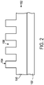
- the patterned layer 150 may comprise a residual layer 152 and a plurality of features shown as protrusions 154 and recessions 156.
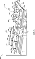
- FIG. 3 illustrates a perspective view of a substrate loading system 302.
- the substrate loading system 302 facilitates loading and unloading of substrates to and from one or more stations (e.g., pedestals and/or substrate chucks).
- the substrate loading system 302 includes a tray handler device 304 including a first tray handler 306 positioned opposite a second tray handler 308.
- the first tray handler 306 and the second tray handler 308 can include one or more arms 309.
- the substrate loading system 302 further includes a first tray 310 and a second tray 312.
- the first tray 310 and the second tray 312 each have a top surface 314, 316, respectively.
- the first tray 310 defines apertures 318a, 318b, 318c, 318d (collectively referred to as apertures 318) and the second tray 312 defines apertures 320a, 320b, 320c, 320d (collectively referred to as apertures 320).
- the first tray 310 and the second tray 312 can define any number of apertures.
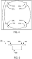
- Each of the apertures 318, 320 define cutouts and tabs. Specifically, FIG.
- each of the apertures 318, 320 can include any number of cutouts 322 and tabs 324.
- the tabs 324 include a high friction material positioned thereon, such as Viton ® (available from The Chemours Company), Kalrez ® (available from the DuPont TM ), or Simriz ® (available from Freudenberg Sealing Technologies).
- the substrate loading system 302 further includes substrate chucks 326a, 326b, 326c, 326d (collectively referred to as substrate chucks 326); however, the system 302 can include any number of substrate chucks 326.
- FIG. 5 illustrates a side view of one of the substrate chucks 326.
- the substrate chuck 326 includes a top surface 328 positioned opposite a bottom surface 330.
- the substrate chuck 326 also includes channels 332 positioned at a perimeter of each substrate chuck 326. In some examples, for a particular aperture 318, 320, the quantity of the channels 332 matches the quantity of the tabs 324 of the particular aperture 318, 320.
- the substrate loading system 302 further includes a pedestal platform 334 that includes a plurality of pedestals 336 extending from a top surface 337, shown in FIG. 6 .
- a first subset of the pedestals 336 can be associated with a first height
- a second subset of the pedestals 336 can be associated with a second height.
- the substrate loading system 302 further includes an actuator system 340 and a rotational system 342.
- the actuator system 340 includes a first actuator module 341 and a second actuator module 343.
- the actuator system 340 increases and/or decreases a relative positioning of the tray handler device 304, and specifically, the first tray handler 306 and the second tray handler 308, with respect to the substrate chucks 326 and the pedestals 336.
- the rotational system 342 rotates the tray handler device 304 with respect to an axis 344.
- the substrate loading system 302 further includes an air bearing 350 and a support structure 352. In some examples, the air bearing 350 facilitates movement of the substrate chucks 326 about the support structure 352.
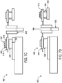
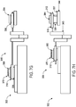
- the substrate loading system 302 is shown facilitating loading and unloading of substrates to and from the pedestals 336 and the substrate chuck 326.
- the first tray handler 306 engages with the first tray 310.
- the first tray handler 306 engaging with the first tray 310 can include coupling the first tray handler 306 and the first tray 310.
- the arms 309 of the first tray handler 306 engage with the first tray 310 at a perimeter of the first tray 310.
- the substrate loading system 302 positions the tray handler device 304 to be in a first position.
- positioning the tray handler device 304 in the first position includes having the cutouts 322 of the each of the apertures 318 of the first tray 310 in superimposition with respective pedestals 336 of the pedestal platform 334.
- positioning the tray handler device 304 in the first position includes a distal end 354 of each of the pedestals 336 extend away from the top surface 314 of the first tray 310.
- the actuator module 341 increases a distance between the top surface 314 of the first tray 310 and the top surface 337 of the pedestal platform 334.
- increasing the distance between the top surface 314 of the first tray 310 and the top surface 337 of the pedestal platform 334 includes transferring a first substrate 360 from being positioned on the pedestals 336 to the tabs 324 defined by the apertures 318 of the first tray 310.
- transferring the first substrate 360 from being positioned on the pedestals 336 to the tabs 324 defined by the apertures 318 of the first tray 310 includes transferring the first substrate 360 from being positioned on the pedestals 336 to the tabs 324 defined by the apertures 318 of the first tray 310 while the second tray handler 308 is engaging with the second tray 312.
- the second tray handler 308 engaging with the second tray 312 can include coupling the second tray handler 308 and the second tray 312.
- the arms 309 of the second tray handler 308 engage with the second tray 312 at a perimeter of the second tray 312.
- contact with the first substrate 360 is minimized. That is, by contacting the first substrate 360 with only the tabs 324 defined by the apertures 318 of the first tray 310, contact between such is minimized.
- contact with the first substrate 360 e.g., by the tabs 324, introduction of possible defects to the first substrate 360 are minimized, as well as, minimizing particle contamination of the first substrate 360 by the tray handler device 302.
- the actuator module 343 increases a distance between the top surface 316 of the second tray 312 and the bottom surface 330 of the substrate chuck 326.
- increasing the distance between the top surface 316 of the second tray 312 and bottom surface 330 of the substrate chuck 326 includes transferring a second substrate 362 from being positioned on the substrate chuck 326 to the tabs 324 defined by the aperture 320 of the second tray 312.
- the second substrate 326 includes a patterned layer 351 positioned thereon prior to transferring the second substrate 362 from the substrate chuck 326 to the tabs 324 defined by the aperture 320 of the second tray 312.
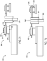
- the rotational system 342 rotates the tray handler device 304 from the first position to a second position. Specifically, the rotational system 342 rotates the tray handler device 304 about the axis 344 such that the tray handler device 304 is in the second position. In some examples, positioning the tray handler device 304 in the second position includes having the tabs 324 defined by the apertures 318 of the first tray 310 in superimposition with the channels 332 of the substrate chuck 326. In some examples, positioning the tray handler device 304 in the second position includes having the cutouts 322 of each of the apertures 320 of the second tray 312 in superimposition with the respective pedestals 336 of the pedestal platform 334.
- the actuator module 341 decreases a distance between the top surface 314 of the first tray 310 and the bottom surface 330 of the substrate chuck 326.
- decreasing the distance between the top surface 314 of the first tray 310 and the bottom surface 330 of the substrate chuck 326 includes transferring the first substrate 360 from the tabs 324 defined by the aperture 318 of the first tray 310 to the top surface 322 of the substrate chuck 326 while the tabs 324 defined by the aperture 318 of the first tray 310 are disposed within the respective channels 332 of the substrate chuck 326.
- the first tray handler 306 disengages from the first tray 310. That is, the first tray handler 306 disengaging from the first tray 310 can include decoupling the first tray handler 306 and the first tray 310. In some examples, the arms 309 of the first tray handler 306 disengage from the first tray 310 at the perimeter of the first tray 310. In some examples, the first tray handler 306 disengages from the first tray 310 while concurrently the actuator module 343 decreases a distance between the top surface 316 of the second tray 312 and the top surface 337 of the pedestal platform 334.
- decreasing the distance between the top surface 316 of the second tray 312 and the top surface 337 of the pedestal platform 334 includes transferring the second substrate 362 from be positioned on the tabs 324 defined by the aperture 320 of the second tray 312 to the pedestals 336.
- a patterning system forms a pattern in (or in a layer positioned on) the first substrate 360.
- the air bearing 350 facilitates movement of the substrate chuck 326 about the support structure 352 in a direction away from the tray handler device 304 and towards the patterning system (not shown).
- a robotic system removes the second substrate 362 from being positioned on the pedestals 336.
- the robotic system positions a third substrate 364 on the pedestals 336.
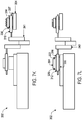
- the patterning system forms a patterned layer 370 positioned on the first substrate 360 while the first substrate 360 is positioned on the substrate chuck 326 and the first tray 310 is coupled to the substrate chuck 326.
- the first tray handler 306 engages with the first tray 310.
- the first tray handler 306 engaging with the first tray 310 can include coupling the first tray handler 306 and the first tray 310.
- the arms 309 of the first tray handler 306 engage with the first tray 310 at a perimeter of the first tray 310.
- the actuator module 343 increases a distance between the top surface 316 of the second tray 312 and the top surface 337 of the pedestals platform 334.
- increasing the distance between the top surface 316 of the second tray 312 and the top surface 337 of the pedestal platform 334 includes transferring the third substrate 364 from being positioned on the pedestals 336 to the tabs 324 defined by the aperture 320 of the second tray 312.
- the actuator module 341 increases the distance between the top surface 314 of the first tray 310 and the bottom surface 330 of the substrate chuck 326.
- increasing the distance between the top surface 314 of the first tray 310 and bottom surface 330 of the substrate chuck 326 includes transferring the first substrate 360 from being positioned on the substrate chuck 326 to the tabs 324 defined by the aperture 318 of the first tray 310.
- the rotational system 342 rotates the tray handler device 304 from the second position to the first position. Specifically, the rotational system 342 rotates the tray handler device 304 about the axis 344 such that the tray handler device 304 is in the first position. In some examples, positioning the tray handler device 304 in the first position includes having the cutouts 322 of the aperture 318 of the first tray 310 in superimposition with respective pedestals 336 of the pedestal platform 334.
- the actuator module 341 decreases the distance between the top surface 314 of the first tray 310 and the top surface 337 of the pedestal platform 334.
- decreasing the distance between the top surface 314 of the first tray 310 and the top surface 337 of the pedestal platform 334 includes transferring the first substrate 360 from be positioned on the tabs 324 defined by the aperture 318 of the first tray 310 to the pedestals 336.
- the actuator module 343 decreases a distance between the top surface 316 of the second tray 312 and the bottom surface 330 of the substrate chuck 326.
- decreasing the distance between the top surface 316 of the second tray 312 and the bottom surface 330 of the substrate chuck 326 includes transferring the third substrate 364 from the tabs 324 defined by the aperture 320 of the second tray 312 to the top surface 322 of the substrate chuck 326 while the tabs 324 defined by the aperture 320 of the second tray 312 are disposed within the respective channels 332 of the substrate chuck 326.
- the second substrate 362 can be processed similar to that described above with respect to the first substrate 360, and specifically, that the process described in FIGS. 7A-7L can be applied to the second substrate 362. In some examples, any of the steps of FIGS. 7A-7L can happen serially, or in parallel.
- a single first substrate 362, a single second substrate 364, a single third substrate 366 and a single substrate chuck 326 are shown; however the process of FIGs. 7A-7L can be applied to a plurality of first substrates 362, a plurality of second substrates 364, and a plurality of third substrate 366 with respect to a plurality of substrate chucks 326. That is, a plurality of first substrates 362, a plurality of second substrates 364, and a plurality of third substrate 366 can be subject to the process of FIGs. 7A-7L , concurrently. In some examples, the process of FIGs.
- the substrate loading system 302 is associated with one complete exchange cycle of the substrates is 5.3 seconds, and the substrate loading system 302, specifically, the tray handler device 304, completes one revolution in 1.5 seconds.
- the substrate loading system 302, and specifically, the rotational system 342 rotates the tray handler device 304 clockwise and/or counterclockwise.
- FIG. 8 illustrates an example method for loading and unloading of substrates to and from pedestals and the substrate chuck.
- the process 800 is illustrated as a collection of referenced acts arranged in a logical flow graph. The order in which the acts are described is not intended to be construed as a limitation, and any number of the described acts can be combined in other orders and/or in parallel to implement the process.
- the tray handler device 304 is provided (802). In some examples, the tray handler device 304 includes the first tray handler 306 positioned opposite the second tray handler 308.
- the first tray 310 and the second tray 312 are provided (804). In some examples, the first tray 310 defines the apertures 318 and the second tray defines the aperture 320. In some examples, the first tray 310 has the top surface 314 and the second tray has the top surface 316. In some examples, each aperture 318, 320 defines at least two cutouts 322 and two tabs 324.
- the substrate chuck 326 is provided (806). In some examples, the substrate chuck 326 includes the top surface 328 and the bottom surface 330. The first tray handler 306 engages with the first tray 310 (808).
- the tray handler device 304 is positioned in a first position (810). In some examples, positioning the tray handler device 304 in the first position includes having the cutouts 322 of the each of the apertures 318 of the first tray 310 in superimposition with respective pedestals 336 of the pedestal platform 334. In some examples, positioning the tray handler device 304 in the first position includes the distal end 354 of each of the pedestals 336 extending away from the top surface 314 of the first tray 310.
- the distance between the top surface 314 of the first tray 310 and the top surface 337 of the pedestal platform 334 is increased (812).
- the actuator module 341 increases the distance between the top surface 314 of the first tray 310 and the top surface 337 of the pedestal platform 334.
- increasing the distance between the top surface 314 of the first tray 310 and the top surface 337 of the pedestal platform 334 includes transferring the first substrate 360 from being positioned on the pedestals 336 to the tabs 324 defined by the apertures 318 of the first tray 310.
- transferring the first substrate 360 from being positioned on the pedestals 336 to the tabs 324 defined by the apertures 318 of the first tray 310 includes transferring the first substrate 360 from being positioned on the pedestals 336 to the tabs 324 defined by the aperture 318 of the first tray 310 while the second tray handler 308 is engaging with the second tray 312.
- the distance between the top surface 316 of the second tray 312 and the bottom surface 330 of the substrate chuck 326 is increased (814).
- the actuator module 343 increases the distance between the top surface 316 of the second tray 312 and the bottom surface 330 of the substrate chuck 326.
- increasing the distance between the top surface 316 of the second tray 312 and bottom surface 330 of the substrate chuck 326 includes transferring the second substrate 362 from being positioned on the substrate chuck 326 to the tabs 324 defined by the aperture 320 of the second tray 312.
- the tray handler device 302 rotates from the first position to the second position (816).
- the rotational system 342 rotates the tray handler device 302 from the first position to a second position.
- positioning the tray handler device 302 in the second position includes having the tabs 324 defined by the apertures 318 of the first tray 310 in superimposition with the channels 332 of the substrate chuck 326.
- positioning the tray handler device 302 in the second position includes having the cutouts 322 of each of the apertures 320 the second tray 312 in superimposition with the respective pedestals 336 of the pedestal platform 334.
- the distance between the top surface 314 of the first tray 310 and the bottom surface 330 of the substrate chuck 326 is decreased (818).
- the actuator module 341 decreases the distance between the top surface 314 of the first tray 310 and the bottom surface 330 of the substrate chuck 326.
- decreasing the distance between the top surface 314 of the first tray 310 and the bottom surface 330 of the substrate chuck 326 includes transferring the first substrate 360 from the tabs 324 defined by the aperture 318 of the first tray 310 to the top surface 322 of the substrate chuck 328 while the tabs 324 defined by the aperture 318 of the first tray 310 are disposed within the respective channels 332 of the substrate chuck 326.
- the first tray handler 306 disengages from the first tray 310 (820). In some examples, the first tray handler 306 disengages from the first tray 310 while concurrently the actuator module 343 decreases a distance between the top surface 316 of the second tray 312 and the top surface 337 of the pedestal platform 334. In some examples, decreasing the distance between the top surface 316 of the second tray 312 and the top surface 337 of the pedestal platform 334 includes transferring the second substrate 362 from be positioned on the tabs 324 defined by the aperture 320 of the second tray 312 to the pedestals 336.
Landscapes
- Physics & Mathematics (AREA)
- General Physics & Mathematics (AREA)
- Container, Conveyance, Adherence, Positioning, Of Wafer (AREA)
- Mechanical Treatment Of Semiconductor (AREA)
- Exposure Of Semiconductors, Excluding Electron Or Ion Beam Exposure (AREA)
- Shaping Of Tube Ends By Bending Or Straightening (AREA)
Claims (13)
- Procédé de transfert de substrat par lithographie par impression, comprenant les étapes suivantes consistant à :prévoir un dispositif de manipulation de plateaux (304) comprenant un premier manipulateur de plateaux (306) positionné à l'opposé d'un deuxième manipulateur de plateaux (308) ;prévoir un premier plateau (310) et un deuxième plateau (312), chacun des premier et deuxième plateaux définissant une ouverture (318, 320) et ayant chacun une surface supérieure (314, 316), chaque ouverture définissant au moins deux découpes (322) et deux pattes (324) ;prévoir un mandrin de substrat (326) ayant une surface supérieure (328) et une surface inférieure (330) ;engager le premier manipulateur de plateaux (306) avec le premier plateau (310) ;positionner le dispositif de manipulation de plateaux dans une première position avec i) les découpes (322) de l'ouverture (318) du premier plateau (310) en superposition avec des socles (336) respectifs d'une plate-forme de socles (334) et ii) une extrémité distale (354) des socles (336) s'étendant à distance de la surface supérieure (314) du premier plateau (310) ;augmenter une distance entre la surface supérieure (314) du premier plateau (310) et une surface supérieure (337) de la plate-forme de socles (334) afin de transférer un premier substrat (360) depuis les socles (336) aux pattes (324) définies par l'ouverture (318) du premier plateau (310), tout en engageant simultanément le deuxième manipulateur de plateaux (308) avec le deuxième plateau (312) ;augmenter une distance entre la surface supérieure (316) du deuxième plateau (312) et la surface inférieure (330) du mandrin de substrat (326) pour transférer un deuxième substrat (362) depuis le mandrin de substrat (326) aux pattes (324) définies par le deuxième plateau ;faire pivoter le dispositif de manipulation de plateaux (304) de la première position à une deuxième position avec i) les pattes (324) définies par l'ouverture (318) du premier plateau (310) en superposition avec les canaux (332) respectifs du mandrin de substrat (326) et ii) les découpes (322) de l'ouverture (320) du deuxième plateau (312) en superposition avec les socles (336) respectifs ;diminuer une distance entre la surface supérieure (314) du premier plateau (310) et la surface inférieure (330) du mandrin de substrat (326) afin de transférer le premier substrat (360) depuis les pattes (324) définies par l'ouverture (318) du premier plateau (310) à la surface supérieure (328) du mandrin de substrat (326), tandis que les pattes (324) définies par l'ouverture (318) du premier plateau (310) sont disposées à l'intérieur des canaux (332) respectifs du mandrin de substrat (326) ; etdésengager le premier manipulateur de plateaux (306) du premier plateau (310) tout en diminuant simultanément une distance entre la surface supérieure (316) du deuxième plateau (312) et la surface supérieure (337) de la plate-forme de socles (334) afin de transférer le deuxième substrat (362) depuis les pattes (324) définies par l'ouverture (320) du deuxième plateau aux socles (336).
- Procédé selon la revendication 1, comprenant en outre les étapes suivantes consistant à :retirer le deuxième substrat de son positionnement sur les socles ;positionner un troisième substrat sur les socles ;et après avoir désengagé le premier manipulateur de plateaux depuis le premier plateau, former un motif dans un matériau positionné sur le premier substrat, tandis que le premier substrat est positionné sur le mandrin de substrat et le premier plateau est couplé au mandrin de substrat.
- Procédé selon la revendication 2, comprenant en outre l'étape suivante consistant à :après avoir formé le motif dans le matériau positionné sur le premier substrat, engager le premier manipulateur de plateaux avec le premier plateau tout en augmentant simultanément la distance entre la surface supérieure du deuxième plateau et la surface supérieure de la plateforme de socles afin de transférer le troisième substrat depuis les socles aux pattes définies par l'ouverture du deuxième plateau.
- Procédé selon la revendication 3, comprenant en outre l'étape suivante consistant à :
après avoir engagé le premier manipulateur de plateaux avec le premier plateau, augmenter la distance entre la surface supérieure du premier plateau et la surface inférieure du mandrin de substrat afin de transférer le premier substrat depuis le mandrin de substrat aux pattes de définies par le premier plateau. - Procédé selon la revendication 4, comprenant en outre l'étape suivante consistant à :
après avoir augmenté la distance entre la surface supérieure du premier plateau et la surface inférieure du mandrin de substrat, faire pivoter le dispositif de manipulation de plateau depuis la deuxième position vers la première position avec les découpes de l'ouverture du premier plateau en superposition avec les socles respectifs de la plateforme de socles. - Procédé selon la revendication 5, comprenant en outre l'étape consistant à diminuer la distance entre la surface supérieure du premier plateau et la surface supérieure de la plateforme de socles afin de transférer le premier substrat depuis les pattes définies par l'ouverture du premier plateau aux socles.
- Procédé selon la revendication 6, comprenant en outre l'étape consistant à diminuer la distance entre la surface supérieure du deuxième plateau et la surface inférieure du mandrin de substrat afin de transférer le troisième substrat depuis les pattes définies par l'ouverture du deuxième plateau à la surface supérieure du mandrin de substrat, tandis que les pattes définies par l'ouverture du deuxième plateau sont disposées dans les canaux respectifs du mandrin de substrat.
- Procédé selon la revendication 1, dans lequel le second substrat comprend une couche à motif positionnée sur celui-ci avant de transférer le deuxième substrat depuis le mandrin de substrat aux pattes définies par le deuxième plateau.
- Système de lithographie par impression (100), comprenant ;deux ou plusieurs socles (336) d'une plate-forme de socles (334) ;un mandrin de substrat (326) ayant une surface supérieure (328) et une surface inférieure (330), et comprenant des canaux (332) ;un premier plateau (310) et un deuxième plateau (312), chacun des premier et second plateaux (310, 312) définissant une ouverture (318, 320) et ayant chacun une surface supérieure (314, 316), chaque ouverture (318, 320) définissant au moins deux découpes (322) et deux pattes (324) ;un dispositif de manipulation de plateaux (304) comprenant un premier manipulateur de plateaux (306) positionné à l'opposé d'un deuxième manipulateur de plateaux (308), le premier manipulateur de plateaux (306) pouvant s'engager avec le premier plateau (310) et le deuxième manipulateur de plateaux (308) pouvant s'engager avec le deuxième plateau (312), le dispositif de manipulation de plateaux (304) pouvant pivoter entre des première et deuxième positions, la première position ayant i) les découpes (322) de l'ouverture (318) du premier plateau (310) en superposition avec les socles (336) respectifs d'une plate-forme de socles (334) et ii) une extrémité distale (354) des socles (336) s'étendant à distance de la surface supérieure (314) du premier plateau (310), la deuxième position ayant i) les pattes (324) définies par l'ouverture (318) du premier plateau (310) en superposition avec les canaux (332) respectifs du mandrin de substrat (326) et ii) les découpes (322) de l'ouverture (320) du deuxième plateau (312) en superposition avec les socles (336) respectifs ; etun système d'actionnement (340) pour, lorsque le dispositif de manipulation de plateaux (304) est dans la première position, i) augmenter une distance entre la surface supérieure (314) du premier plateau (310) et une surface supérieure (337) de la plate-forme de socles (334) afin de transférer un premier substrat (360) depuis les socles (336) aux pattes (324) définies par l'ouverture (318) du premier plateau (310), tout en engageant simultanément le deuxième manipulateur de plateaux (308) avec le deuxième plateau (312), et ii) augmenter une distance entre la surface supérieure (316) du deuxième plateau (312) et la surface inférieure (330) du mandrin de substrat (326) afin de transférer un deuxième substrat (362) depuis le mandrin de substrat (326) aux pattes (324) définies par le deuxième plateau (312), et lorsque le dispositif de manipulation de plateaux (304) est dans la deuxième position, i) diminuer une distance entre la surface supérieure (314) du premier plateau (310) et la surface inférieure (330) du mandrin de substrat (326) afin de transférer le premier substrat (360) depuis les pattes (324) définies par l'ouverture (318) du premier plateau (310) à la surface supérieure (328) du mandrin de substrat (326), tandis que les pattes (324) définies par l'ouverture (318) du premier plateau (310) sont disposées à l'intérieur des canaux (322) respectifs du mandrin de substrat (326), et ii) diminuer une distance entre la surface supérieure (316) du deuxième plateau (312) et la surface supérieure (337) de la plate-forme de socles (334) afin de transférer le deuxième substrat (362) depuis les pattes (324) définies par l'ouverture (320) du deuxième plateau (312) aux socles (336), tandis que le premier manipulateur de plateaux (306) est désengagé du premier plateau (310).
- Système selon la revendication 9, comprenant en outre un système de rotation afin de faire pivoter le dispositif de manipulation de plateaux entre les première et deuxième positions.
- Système selon la revendication 9, comprenant en outre un système de formation de motif afin de former un motif dans le premier substrat lorsque le premier substrat est positionné sur la surface supérieure du mandrin de substrat.
- Système selon la revendication 9, le système d'actionnement comprend un premier module d'actionnement, le premier module d'actionnement, lorsque le dispositif de manipulation de plateaux est dans la première position, augmenter la distance entre la surface supérieure du premier plateau et une surface supérieure de la plate-forme de socles afin de transférer un premier substrat depuis les socles aux pattes définies par l'ouverture du premier plateau, tout en engageant simultanément le deuxième manipulateur de plateaux avec le second plateau, et lorsque le dispositif de manipulation de plateaux est dans la deuxième position, diminuer la distance entre la surface supérieure du premier plateau et la surface inférieure du mandrin de substrat afin de transférer le premier substrat depuis les pattes définies par l'ouverture du premier plateau à la surface supérieure du mandrin de substrat, tandis que les pattes définies par l'ouverture du premier plateau sont disposées à l'intérieur des canaux respectifs du mandrin de substrat.
- Système selon la revendication 12, le système d'actionnement comprend un deuxième module d'actionnement, le deuxième module d'actionnement, lorsque le manipulateur de plateaux est dans la première position, augmente une distance entre la surface supérieure du deuxième plateau et la surface inférieure du mandrin de substrat afin de transférer un deuxième substrat depuis le mandrin de substrat aux pattes définies par le deuxième plateau, et lorsque le manipulateur de plateaux est dans la deuxième position, et lorsque le dispositif de manipulation de plateaux est dans la deuxième position, diminuer la distance entre la surface supérieure du deuxième plateau et la surface supérieure de la plate-forme de socles afin de transférer le deuxième substrat depuis les pattes définies par l'ouverture du deuxième plateau aux socles, tandis que le premier manipulateur de plateaux est désengagé du premier plateau.
Priority Applications (1)
| Application Number | Priority Date | Filing Date | Title |
|---|---|---|---|
| EP21213772.3A EP3989269B1 (fr) | 2016-11-03 | 2017-09-27 | Système de chargement de substrat |
Applications Claiming Priority (2)
| Application Number | Priority Date | Filing Date | Title |
|---|---|---|---|
| US201662416916P | 2016-11-03 | 2016-11-03 | |
| PCT/US2017/053706 WO2018084965A1 (fr) | 2016-11-03 | 2017-09-27 | Système de chargement de substrat |
Related Child Applications (1)
| Application Number | Title | Priority Date | Filing Date |
|---|---|---|---|
| EP21213772.3A Division EP3989269B1 (fr) | 2016-11-03 | 2017-09-27 | Système de chargement de substrat |
Publications (3)
| Publication Number | Publication Date |
|---|---|
| EP3535781A1 EP3535781A1 (fr) | 2019-09-11 |
| EP3535781A4 EP3535781A4 (fr) | 2020-07-29 |
| EP3535781B1 true EP3535781B1 (fr) | 2022-01-05 |
Family
ID=62021820
Family Applications (2)
| Application Number | Title | Priority Date | Filing Date |
|---|---|---|---|
| EP17868146.6A Active EP3535781B1 (fr) | 2016-11-03 | 2017-09-27 | Système de chargement de substrat |
| EP21213772.3A Active EP3989269B1 (fr) | 2016-11-03 | 2017-09-27 | Système de chargement de substrat |
Family Applications After (1)
| Application Number | Title | Priority Date | Filing Date |
|---|---|---|---|
| EP21213772.3A Active EP3989269B1 (fr) | 2016-11-03 | 2017-09-27 | Système de chargement de substrat |
Country Status (10)
| Country | Link |
|---|---|
| US (2) | US10475685B2 (fr) |
| EP (2) | EP3535781B1 (fr) |
| JP (1) | JP6824400B2 (fr) |
| KR (1) | KR102263614B1 (fr) |
| CN (2) | CN115642115B (fr) |
| AU (1) | AU2017353824B2 (fr) |
| CA (1) | CA3041069C (fr) |
| IL (2) | IL300011B2 (fr) |
| TW (1) | TWI731182B (fr) |
| WO (1) | WO2018084965A1 (fr) |
Families Citing this family (3)
| Publication number | Priority date | Publication date | Assignee | Title |
|---|---|---|---|---|
| KR102263614B1 (ko) | 2016-11-03 | 2021-06-09 | 몰레큘러 임프린츠 인코퍼레이티드 | 기판 로딩 시스템 |
| JP7418241B2 (ja) * | 2020-02-27 | 2024-01-19 | 東京エレクトロン株式会社 | 位置決め装置、処理システム及び位置決め方法 |
| US20220035245A1 (en) * | 2020-07-31 | 2022-02-03 | Applied Materials, Inc. | Nano imprint stamps |
Family Cites Families (34)
| Publication number | Priority date | Publication date | Assignee | Title |
|---|---|---|---|---|
| US5510723A (en) | 1994-03-01 | 1996-04-23 | Micron Custom Manufacturing, Inc. Usa | Diced semiconductor device handler |
| DE19853092B4 (de) * | 1998-11-18 | 2004-10-21 | Leica Microsystems Lithography Gmbh | Übernahme- und Haltesystem für ein Substrat |
| JP4518712B2 (ja) * | 2001-08-13 | 2010-08-04 | キヤノンアネルバ株式会社 | トレイ式マルチチャンバー基板処理装置 |
| US7179079B2 (en) * | 2002-07-08 | 2007-02-20 | Molecular Imprints, Inc. | Conforming template for patterning liquids disposed on substrates |
| US7070405B2 (en) * | 2002-08-01 | 2006-07-04 | Molecular Imprints, Inc. | Alignment systems for imprint lithography |
| JP4425146B2 (ja) | 2002-12-02 | 2010-03-03 | パナソニック株式会社 | 部品供給装置 |
| JP3890026B2 (ja) * | 2003-03-10 | 2007-03-07 | 東京エレクトロン株式会社 | 液処理装置および液処理方法 |
| DE10343323A1 (de) * | 2003-09-11 | 2005-04-07 | Carl Zeiss Smt Ag | Stempellithografieverfahren sowie Vorrichtung und Stempel für die Stempellithografie |
| US20050155554A1 (en) * | 2004-01-20 | 2005-07-21 | Saito Toshiyuki M. | Imprint embossing system |
| KR100972249B1 (ko) * | 2005-08-11 | 2010-07-26 | 어드밴스드 마이크로 패브리케이션 이큅먼트 인코퍼레이티드 아시아 | 반도체 공작물 적재/이재 장치 및 적재/이재 방법 |
| KR101153118B1 (ko) * | 2005-10-12 | 2012-06-07 | 파나소닉 주식회사 | 플라즈마 처리장치 및 플라즈마 처리방법 |
| JP4361045B2 (ja) * | 2005-10-12 | 2009-11-11 | パナソニック株式会社 | プラズマ処理装置及びプラズマ処理方法 |
| US7670530B2 (en) * | 2006-01-20 | 2010-03-02 | Molecular Imprints, Inc. | Patterning substrates employing multiple chucks |
| EP1832933B1 (fr) * | 2006-03-08 | 2008-10-01 | Erich Thallner | Procédé de fabrication d'un dispositif et appareil de traitement d'un substrat, et support de substrat |
| JP2008251754A (ja) | 2007-03-29 | 2008-10-16 | Nikon Corp | 基板搬送方法及び装置、並びに露光方法及び装置 |
| NL1036859A1 (nl) * | 2008-04-29 | 2009-10-30 | Asml Netherlands Bv | Support structure, inspection apparatus, lithographic apparatus and methods for loading and unloading substrates. |
| JP5142818B2 (ja) * | 2008-05-20 | 2013-02-13 | 株式会社日立ハイテクノロジーズ | プロキシミティ露光装置、プロキシミティ露光装置のチャック高さ調整方法、及び表示用パネル基板の製造方法 |
| JP5088335B2 (ja) | 2009-02-04 | 2012-12-05 | 東京エレクトロン株式会社 | 基板搬送装置及び基板処理システム |
| KR102027108B1 (ko) * | 2009-03-18 | 2019-10-01 | 에바텍 아크티엔게젤샤프트 | 진공처리 장치 |
| WO2010109848A1 (fr) * | 2009-03-26 | 2010-09-30 | パナソニック株式会社 | Appareil de traitement au plasma et procédé de traitement au plasma |
| JP2011086795A (ja) * | 2009-10-16 | 2011-04-28 | Ulvac Japan Ltd | 基板搬送装置及びこの基板搬送装置を備えた真空処理システム |
| US20110141448A1 (en) * | 2009-11-27 | 2011-06-16 | Nikon Corporation | Substrate carrier device, substrate carrying method, substrate supporting member, substrate holding device, exposure apparatus, exposure method and device manufacturing method |
| JP5485806B2 (ja) * | 2010-06-16 | 2014-05-07 | パスカルエンジニアリング株式会社 | 金型位置決め固定装置 |
| US9864279B2 (en) * | 2010-08-05 | 2018-01-09 | Asml Netherlands B.V. | Imprint lithography |
| JP5550600B2 (ja) * | 2011-04-13 | 2014-07-16 | パナソニック株式会社 | プラズマ処理装置及びプラズマ処理方法 |
| KR101877600B1 (ko) * | 2011-11-25 | 2018-07-12 | 신에츠 엔지니어링 가부시키가이샤 | 기판 반송 장치 및 기판 조립 라인 |
| KR101403326B1 (ko) * | 2012-08-01 | 2014-06-05 | 엘아이지에이디피 주식회사 | 박막증착용 기판 트레이,박막증착장비 및 박막증착방법 |
| KR101565535B1 (ko) * | 2013-12-06 | 2015-11-06 | 피에스케이 주식회사 | 기판 처리 장치 및 기판 처리 방법 |
| JP6303592B2 (ja) * | 2014-02-25 | 2018-04-04 | 東京エレクトロン株式会社 | 基板処理装置 |
| KR101504880B1 (ko) * | 2014-11-14 | 2015-03-20 | 주식회사 기가레인 | 기판 안착유닛 |
| KR20160063969A (ko) * | 2014-11-27 | 2016-06-07 | 한국알박(주) | 기판 이송 장치 |
| US10248018B2 (en) * | 2015-03-30 | 2019-04-02 | Canon Kabushiki Kaisha | Imprint apparatus and method of manufacturing article |
| CN109804309B (zh) * | 2016-07-29 | 2022-09-02 | 分子印记公司 | 微光刻中的基板加载 |
| KR102263614B1 (ko) | 2016-11-03 | 2021-06-09 | 몰레큘러 임프린츠 인코퍼레이티드 | 기판 로딩 시스템 |
-
2017
- 2017-09-27 KR KR1020197015796A patent/KR102263614B1/ko active Active
- 2017-09-27 WO PCT/US2017/053706 patent/WO2018084965A1/fr not_active Ceased
- 2017-09-27 CN CN202211362894.XA patent/CN115642115B/zh active Active
- 2017-09-27 CA CA3041069A patent/CA3041069C/fr active Active
- 2017-09-27 CN CN201780067080.4A patent/CN109923658B/zh active Active
- 2017-09-27 JP JP2019522274A patent/JP6824400B2/ja active Active
- 2017-09-27 EP EP17868146.6A patent/EP3535781B1/fr active Active
- 2017-09-27 IL IL300011A patent/IL300011B2/en unknown
- 2017-09-27 AU AU2017353824A patent/AU2017353824B2/en active Active
- 2017-09-27 EP EP21213772.3A patent/EP3989269B1/fr active Active
- 2017-09-27 US US15/717,482 patent/US10475685B2/en active Active
- 2017-10-18 TW TW106135639A patent/TWI731182B/zh active
-
2019
- 2019-04-28 IL IL266272A patent/IL266272B2/en unknown
- 2019-11-08 US US16/677,919 patent/US11195739B2/en active Active
Also Published As
| Publication number | Publication date |
|---|---|
| WO2018084965A1 (fr) | 2018-05-11 |
| JP2019536263A (ja) | 2019-12-12 |
| CA3041069A1 (fr) | 2018-05-11 |
| IL266272A (en) | 2019-06-30 |
| KR20190071811A (ko) | 2019-06-24 |
| CN115642115B (zh) | 2026-03-27 |
| IL300011A (en) | 2023-03-01 |
| AU2017353824A1 (en) | 2019-05-02 |
| CN109923658A (zh) | 2019-06-21 |
| EP3989269A1 (fr) | 2022-04-27 |
| TW201820513A (zh) | 2018-06-01 |
| IL266272B2 (en) | 2023-07-01 |
| CN109923658B (zh) | 2022-11-04 |
| JP6824400B2 (ja) | 2021-02-03 |
| IL300011B2 (en) | 2024-03-01 |
| US11195739B2 (en) | 2021-12-07 |
| KR102263614B1 (ko) | 2021-06-09 |
| IL266272B1 (en) | 2023-03-01 |
| CN115642115A (zh) | 2023-01-24 |
| IL300011B1 (en) | 2023-11-01 |
| US20180122657A1 (en) | 2018-05-03 |
| AU2017353824B2 (en) | 2021-04-22 |
| CA3041069C (fr) | 2025-04-22 |
| EP3535781A1 (fr) | 2019-09-11 |
| US10475685B2 (en) | 2019-11-12 |
| EP3535781A4 (fr) | 2020-07-29 |
| EP3989269B1 (fr) | 2023-09-27 |
| TWI731182B (zh) | 2021-06-21 |
| US20200098596A1 (en) | 2020-03-26 |
Similar Documents
| Publication | Publication Date | Title |
|---|---|---|
| US7670530B2 (en) | Patterning substrates employing multiple chucks | |
| US11195739B2 (en) | Substrate loading system | |
| US10317806B2 (en) | Substrate loading in microlithography |
Legal Events
| Date | Code | Title | Description |
|---|---|---|---|
| STAA | Information on the status of an ep patent application or granted ep patent |
Free format text: STATUS: THE INTERNATIONAL PUBLICATION HAS BEEN MADE |
|
| PUAI | Public reference made under article 153(3) epc to a published international application that has entered the european phase |
Free format text: ORIGINAL CODE: 0009012 |
|
| STAA | Information on the status of an ep patent application or granted ep patent |
Free format text: STATUS: REQUEST FOR EXAMINATION WAS MADE |
|
| 17P | Request for examination filed |
Effective date: 20190415 |
|
| AK | Designated contracting states |
Kind code of ref document: A1 Designated state(s): AL AT BE BG CH CY CZ DE DK EE ES FI FR GB GR HR HU IE IS IT LI LT LU LV MC MK MT NL NO PL PT RO RS SE SI SK SM TR |
|
| AX | Request for extension of the european patent |
Extension state: BA ME |
|
| DAV | Request for validation of the european patent (deleted) | ||
| DAX | Request for extension of the european patent (deleted) | ||
| A4 | Supplementary search report drawn up and despatched |
Effective date: 20200626 |
|
| RIC1 | Information provided on ipc code assigned before grant |
Ipc: B29C 59/02 20060101ALI20200622BHEP Ipc: G03F 7/20 20060101ALI20200622BHEP Ipc: G03F 7/00 20060101ALI20200622BHEP Ipc: H01L 21/68 20060101AFI20200622BHEP Ipc: H01L 21/67 20060101ALI20200622BHEP Ipc: B29C 43/02 20060101ALI20200622BHEP Ipc: B29C 59/00 20060101ALI20200622BHEP Ipc: H01L 21/687 20060101ALI20200622BHEP |
|
| RIC1 | Information provided on ipc code assigned before grant |
Ipc: H01L 21/68 20060101AFI20210609BHEP Ipc: H01L 21/687 20060101ALI20210609BHEP Ipc: G03F 7/20 20060101ALI20210609BHEP Ipc: H01L 21/67 20060101ALI20210609BHEP Ipc: G03F 7/00 20060101ALI20210609BHEP Ipc: B29C 59/02 20060101ALI20210609BHEP Ipc: B29C 59/00 20060101ALI20210609BHEP Ipc: B29C 43/02 20060101ALI20210609BHEP Ipc: H01L 21/677 20060101ALI20210609BHEP |
|
| GRAP | Despatch of communication of intention to grant a patent |
Free format text: ORIGINAL CODE: EPIDOSNIGR1 |
|
| STAA | Information on the status of an ep patent application or granted ep patent |
Free format text: STATUS: GRANT OF PATENT IS INTENDED |
|
| INTG | Intention to grant announced |
Effective date: 20210720 |
|
| GRAS | Grant fee paid |
Free format text: ORIGINAL CODE: EPIDOSNIGR3 |
|
| GRAA | (expected) grant |
Free format text: ORIGINAL CODE: 0009210 |
|
| STAA | Information on the status of an ep patent application or granted ep patent |
Free format text: STATUS: THE PATENT HAS BEEN GRANTED |
|
| AK | Designated contracting states |
Kind code of ref document: B1 Designated state(s): AL AT BE BG CH CY CZ DE DK EE ES FI FR GB GR HR HU IE IS IT LI LT LU LV MC MK MT NL NO PL PT RO RS SE SI SK SM TR |
|
| REG | Reference to a national code |
Ref country code: GB Ref legal event code: FG4D |
|
| REG | Reference to a national code |
Ref country code: CH Ref legal event code: EP |
|
| REG | Reference to a national code |
Ref country code: AT Ref legal event code: REF Ref document number: 1461329 Country of ref document: AT Kind code of ref document: T Effective date: 20220115 |
|
| REG | Reference to a national code |
Ref country code: DE Ref legal event code: R096 Ref document number: 602017052047 Country of ref document: DE |
|
| REG | Reference to a national code |
Ref country code: IE Ref legal event code: FG4D |
|
| REG | Reference to a national code |
Ref country code: NL Ref legal event code: FP |
|
| REG | Reference to a national code |
Ref country code: LT Ref legal event code: MG9D |
|
| REG | Reference to a national code |
Ref country code: AT Ref legal event code: MK05 Ref document number: 1461329 Country of ref document: AT Kind code of ref document: T Effective date: 20220105 |
|
| PG25 | Lapsed in a contracting state [announced via postgrant information from national office to epo] |
Ref country code: SE Free format text: LAPSE BECAUSE OF FAILURE TO SUBMIT A TRANSLATION OF THE DESCRIPTION OR TO PAY THE FEE WITHIN THE PRESCRIBED TIME-LIMIT Effective date: 20220105 Ref country code: RS Free format text: LAPSE BECAUSE OF FAILURE TO SUBMIT A TRANSLATION OF THE DESCRIPTION OR TO PAY THE FEE WITHIN THE PRESCRIBED TIME-LIMIT Effective date: 20220105 Ref country code: PT Free format text: LAPSE BECAUSE OF FAILURE TO SUBMIT A TRANSLATION OF THE DESCRIPTION OR TO PAY THE FEE WITHIN THE PRESCRIBED TIME-LIMIT Effective date: 20220505 Ref country code: NO Free format text: LAPSE BECAUSE OF FAILURE TO SUBMIT A TRANSLATION OF THE DESCRIPTION OR TO PAY THE FEE WITHIN THE PRESCRIBED TIME-LIMIT Effective date: 20220405 Ref country code: LT Free format text: LAPSE BECAUSE OF FAILURE TO SUBMIT A TRANSLATION OF THE DESCRIPTION OR TO PAY THE FEE WITHIN THE PRESCRIBED TIME-LIMIT Effective date: 20220105 Ref country code: HR Free format text: LAPSE BECAUSE OF FAILURE TO SUBMIT A TRANSLATION OF THE DESCRIPTION OR TO PAY THE FEE WITHIN THE PRESCRIBED TIME-LIMIT Effective date: 20220105 Ref country code: ES Free format text: LAPSE BECAUSE OF FAILURE TO SUBMIT A TRANSLATION OF THE DESCRIPTION OR TO PAY THE FEE WITHIN THE PRESCRIBED TIME-LIMIT Effective date: 20220105 Ref country code: BG Free format text: LAPSE BECAUSE OF FAILURE TO SUBMIT A TRANSLATION OF THE DESCRIPTION OR TO PAY THE FEE WITHIN THE PRESCRIBED TIME-LIMIT Effective date: 20220405 |
|
| PG25 | Lapsed in a contracting state [announced via postgrant information from national office to epo] |
Ref country code: PL Free format text: LAPSE BECAUSE OF FAILURE TO SUBMIT A TRANSLATION OF THE DESCRIPTION OR TO PAY THE FEE WITHIN THE PRESCRIBED TIME-LIMIT Effective date: 20220105 Ref country code: LV Free format text: LAPSE BECAUSE OF FAILURE TO SUBMIT A TRANSLATION OF THE DESCRIPTION OR TO PAY THE FEE WITHIN THE PRESCRIBED TIME-LIMIT Effective date: 20220105 Ref country code: GR Free format text: LAPSE BECAUSE OF FAILURE TO SUBMIT A TRANSLATION OF THE DESCRIPTION OR TO PAY THE FEE WITHIN THE PRESCRIBED TIME-LIMIT Effective date: 20220406 Ref country code: FI Free format text: LAPSE BECAUSE OF FAILURE TO SUBMIT A TRANSLATION OF THE DESCRIPTION OR TO PAY THE FEE WITHIN THE PRESCRIBED TIME-LIMIT Effective date: 20220105 Ref country code: AT Free format text: LAPSE BECAUSE OF FAILURE TO SUBMIT A TRANSLATION OF THE DESCRIPTION OR TO PAY THE FEE WITHIN THE PRESCRIBED TIME-LIMIT Effective date: 20220105 |
|
| PG25 | Lapsed in a contracting state [announced via postgrant information from national office to epo] |
Ref country code: IS Free format text: LAPSE BECAUSE OF FAILURE TO SUBMIT A TRANSLATION OF THE DESCRIPTION OR TO PAY THE FEE WITHIN THE PRESCRIBED TIME-LIMIT Effective date: 20220505 |
|
| REG | Reference to a national code |
Ref country code: DE Ref legal event code: R097 Ref document number: 602017052047 Country of ref document: DE |
|
| PG25 | Lapsed in a contracting state [announced via postgrant information from national office to epo] |
Ref country code: SM Free format text: LAPSE BECAUSE OF FAILURE TO SUBMIT A TRANSLATION OF THE DESCRIPTION OR TO PAY THE FEE WITHIN THE PRESCRIBED TIME-LIMIT Effective date: 20220105 Ref country code: SK Free format text: LAPSE BECAUSE OF FAILURE TO SUBMIT A TRANSLATION OF THE DESCRIPTION OR TO PAY THE FEE WITHIN THE PRESCRIBED TIME-LIMIT Effective date: 20220105 Ref country code: RO Free format text: LAPSE BECAUSE OF FAILURE TO SUBMIT A TRANSLATION OF THE DESCRIPTION OR TO PAY THE FEE WITHIN THE PRESCRIBED TIME-LIMIT Effective date: 20220105 Ref country code: EE Free format text: LAPSE BECAUSE OF FAILURE TO SUBMIT A TRANSLATION OF THE DESCRIPTION OR TO PAY THE FEE WITHIN THE PRESCRIBED TIME-LIMIT Effective date: 20220105 Ref country code: DK Free format text: LAPSE BECAUSE OF FAILURE TO SUBMIT A TRANSLATION OF THE DESCRIPTION OR TO PAY THE FEE WITHIN THE PRESCRIBED TIME-LIMIT Effective date: 20220105 Ref country code: CZ Free format text: LAPSE BECAUSE OF FAILURE TO SUBMIT A TRANSLATION OF THE DESCRIPTION OR TO PAY THE FEE WITHIN THE PRESCRIBED TIME-LIMIT Effective date: 20220105 |
|
| PLBE | No opposition filed within time limit |
Free format text: ORIGINAL CODE: 0009261 |
|
| STAA | Information on the status of an ep patent application or granted ep patent |
Free format text: STATUS: NO OPPOSITION FILED WITHIN TIME LIMIT |
|
| PG25 | Lapsed in a contracting state [announced via postgrant information from national office to epo] |
Ref country code: AL Free format text: LAPSE BECAUSE OF FAILURE TO SUBMIT A TRANSLATION OF THE DESCRIPTION OR TO PAY THE FEE WITHIN THE PRESCRIBED TIME-LIMIT Effective date: 20220105 |
|
| 26N | No opposition filed |
Effective date: 20221006 |
|
| PG25 | Lapsed in a contracting state [announced via postgrant information from national office to epo] |
Ref country code: SI Free format text: LAPSE BECAUSE OF FAILURE TO SUBMIT A TRANSLATION OF THE DESCRIPTION OR TO PAY THE FEE WITHIN THE PRESCRIBED TIME-LIMIT Effective date: 20220105 |
|
| PG25 | Lapsed in a contracting state [announced via postgrant information from national office to epo] |
Ref country code: MC Free format text: LAPSE BECAUSE OF FAILURE TO SUBMIT A TRANSLATION OF THE DESCRIPTION OR TO PAY THE FEE WITHIN THE PRESCRIBED TIME-LIMIT Effective date: 20220105 |
|
| REG | Reference to a national code |
Ref country code: CH Ref legal event code: PL |
|
| PG25 | Lapsed in a contracting state [announced via postgrant information from national office to epo] |
Ref country code: LU Free format text: LAPSE BECAUSE OF NON-PAYMENT OF DUE FEES Effective date: 20220927 |
|
| P01 | Opt-out of the competence of the unified patent court (upc) registered |
Effective date: 20230602 |
|
| PG25 | Lapsed in a contracting state [announced via postgrant information from national office to epo] |
Ref country code: LI Free format text: LAPSE BECAUSE OF NON-PAYMENT OF DUE FEES Effective date: 20220930 Ref country code: IT Free format text: LAPSE BECAUSE OF FAILURE TO SUBMIT A TRANSLATION OF THE DESCRIPTION OR TO PAY THE FEE WITHIN THE PRESCRIBED TIME-LIMIT Effective date: 20220105 Ref country code: IE Free format text: LAPSE BECAUSE OF NON-PAYMENT OF DUE FEES Effective date: 20220927 Ref country code: CH Free format text: LAPSE BECAUSE OF NON-PAYMENT OF DUE FEES Effective date: 20220930 |
|
| PG25 | Lapsed in a contracting state [announced via postgrant information from national office to epo] |
Ref country code: HU Free format text: LAPSE BECAUSE OF FAILURE TO SUBMIT A TRANSLATION OF THE DESCRIPTION OR TO PAY THE FEE WITHIN THE PRESCRIBED TIME-LIMIT; INVALID AB INITIO Effective date: 20170927 |
|
| PG25 | Lapsed in a contracting state [announced via postgrant information from national office to epo] |
Ref country code: CY Free format text: LAPSE BECAUSE OF FAILURE TO SUBMIT A TRANSLATION OF THE DESCRIPTION OR TO PAY THE FEE WITHIN THE PRESCRIBED TIME-LIMIT Effective date: 20220105 |
|
| PG25 | Lapsed in a contracting state [announced via postgrant information from national office to epo] |
Ref country code: MK Free format text: LAPSE BECAUSE OF FAILURE TO SUBMIT A TRANSLATION OF THE DESCRIPTION OR TO PAY THE FEE WITHIN THE PRESCRIBED TIME-LIMIT Effective date: 20220105 |
|
| PG25 | Lapsed in a contracting state [announced via postgrant information from national office to epo] |
Ref country code: MT Free format text: LAPSE BECAUSE OF FAILURE TO SUBMIT A TRANSLATION OF THE DESCRIPTION OR TO PAY THE FEE WITHIN THE PRESCRIBED TIME-LIMIT Effective date: 20220105 |
|
| REG | Reference to a national code |
Ref country code: DE Ref legal event code: R082 Ref document number: 602017052047 Country of ref document: DE Representative=s name: LECOMTE, DIDIER, LU |
|
| PGFP | Annual fee paid to national office [announced via postgrant information from national office to epo] |
Ref country code: NL Payment date: 20250820 Year of fee payment: 9 |
|
| PGFP | Annual fee paid to national office [announced via postgrant information from national office to epo] |
Ref country code: DE Payment date: 20250820 Year of fee payment: 9 |
|
| PGFP | Annual fee paid to national office [announced via postgrant information from national office to epo] |
Ref country code: BE Payment date: 20250820 Year of fee payment: 9 Ref country code: GB Payment date: 20250822 Year of fee payment: 9 |
|
| PGFP | Annual fee paid to national office [announced via postgrant information from national office to epo] |
Ref country code: FR Payment date: 20250821 Year of fee payment: 9 |
|
| REG | Reference to a national code |
Ref country code: DE Ref legal event code: R079 Ref document number: 602017052047 Country of ref document: DE Free format text: PREVIOUS MAIN CLASS: H01L0021680000 Ipc: H10P0072500000 |
|
| PG25 | Lapsed in a contracting state [announced via postgrant information from national office to epo] |
Ref country code: TR Free format text: LAPSE BECAUSE OF FAILURE TO SUBMIT A TRANSLATION OF THE DESCRIPTION OR TO PAY THE FEE WITHIN THE PRESCRIBED TIME-LIMIT Effective date: 20220105 |